EP2679500A2 - Behälter für eine Sauerstoffversorgungseinheit, Vorrichtung und System einer Anordnung mehrerer Sauerstoffversorgungsvorrichtungen, wobei jede Sauerstoffversorgungseinheit in einem Behälter gelagert ist, Verfahren zur Steuerung eines Status und/oder eines Statuswechsels eines Behälters - Google Patents
Behälter für eine Sauerstoffversorgungseinheit, Vorrichtung und System einer Anordnung mehrerer Sauerstoffversorgungsvorrichtungen, wobei jede Sauerstoffversorgungseinheit in einem Behälter gelagert ist, Verfahren zur Steuerung eines Status und/oder eines Statuswechsels eines Behälters Download PDFInfo
- Publication number
- EP2679500A2 EP2679500A2 EP13167630.6A EP13167630A EP2679500A2 EP 2679500 A2 EP2679500 A2 EP 2679500A2 EP 13167630 A EP13167630 A EP 13167630A EP 2679500 A2 EP2679500 A2 EP 2679500A2
- Authority
- EP
- European Patent Office
- Prior art keywords
- container
- door
- status
- well
- sensor
- Prior art date
- Legal status (The legal status is an assumption and is not a legal conclusion. Google has not performed a legal analysis and makes no representation as to the accuracy of the status listed.)
- Granted
Links
Images


Classifications
-
- B—PERFORMING OPERATIONS; TRANSPORTING
- B64—AIRCRAFT; AVIATION; COSMONAUTICS
- B64D—EQUIPMENT FOR FITTING IN OR TO AIRCRAFT; FLIGHT SUITS; PARACHUTES; ARRANGEMENTS OR MOUNTING OF POWER PLANTS OR PROPULSION TRANSMISSIONS IN AIRCRAFT
- B64D13/00—Arrangements or adaptations of air-treatment apparatus for aircraft crew or passengers, or freight space, or structural parts of the aircraft
-
- B—PERFORMING OPERATIONS; TRANSPORTING
- B64—AIRCRAFT; AVIATION; COSMONAUTICS
- B64D—EQUIPMENT FOR FITTING IN OR TO AIRCRAFT; FLIGHT SUITS; PARACHUTES; ARRANGEMENTS OR MOUNTING OF POWER PLANTS OR PROPULSION TRANSMISSIONS IN AIRCRAFT
- B64D11/00—Passenger or crew accommodation; Flight-deck installations not otherwise provided for
- B64D11/06—Arrangements of seats, or adaptations or details specially adapted for aircraft seats
- B64D11/0627—Seats combined with storage means
- B64D11/0629—Seats combined with storage means the storage means being specially adapted for emergency equipment
- B64D11/0632—Seats combined with storage means the storage means being specially adapted for emergency equipment for breathing apparatus
-
- B—PERFORMING OPERATIONS; TRANSPORTING
- B64—AIRCRAFT; AVIATION; COSMONAUTICS
- B64D—EQUIPMENT FOR FITTING IN OR TO AIRCRAFT; FLIGHT SUITS; PARACHUTES; ARRANGEMENTS OR MOUNTING OF POWER PLANTS OR PROPULSION TRANSMISSIONS IN AIRCRAFT
- B64D11/00—Passenger or crew accommodation; Flight-deck installations not otherwise provided for
-
- B—PERFORMING OPERATIONS; TRANSPORTING
- B64—AIRCRAFT; AVIATION; COSMONAUTICS
- B64D—EQUIPMENT FOR FITTING IN OR TO AIRCRAFT; FLIGHT SUITS; PARACHUTES; ARRANGEMENTS OR MOUNTING OF POWER PLANTS OR PROPULSION TRANSMISSIONS IN AIRCRAFT
- B64D2231/00—Emergency oxygen systems
- B64D2231/02—Supply or distribution systems
Definitions
- the invention relates to a container for an oxygen supply unit having a container well at least, wherein a container door can be pivotally joined at a container well's edge.
- the invention also relates to an oxygen supply device having an oxygen supply unit stored in the container.
- the invention also relates to a system of an arrangement of a number of oxygen supply devices in a ceiling panel along an aircraft's cabin, in particular along an aircraft's cabin row or alley of seats, wherein in each device an oxygen supply unit is stored in a container.
- a passenger service unit as known in the state of the art are widely used in civil aircraft comprising for instance a reading light, a passenger or crew air or oxygen supply device, oxygen masks, warning lights and the like appliances.
- an oxygen supply unit usually is part of an oxygen supply device wherein the unit is stored in a container of the aforementioned kind.
- one passenger service unit is provided for each seat of a passenger and crew member.
- one single passenger service unit is provided for a number of the seats, for instance in a particular for a row of seats. A row usually is aligned crosswise to an alley of seats.
- Containers of oxygen supply units of the aforementioned kind usually are arranged adjacent to each other, side by side, to allow an arrangement of a number of oxygen supply devices in a ceiling-panel along an aircrafts cabin, in particular along an aircrafts cabin alley of seats.
- Such oxygen supply devices are referred to as OBOGS (on-board-oxygen-generating-systems) and are adapted to temporarily or continuously provide oxygen to a passenger or crew member of an aircraft.
- OBOGS on-board-oxygen-generating-systems
- Various methods of generating oxygen are known; basically one is adapted for physically generating oxygen gas by means of an oxygen pressure cylinder and another one is adapted for chemically generating oxygen by means of a chemical oxygen generator. Thereby a certain amount of air or continuous air flow comprising a sufficient or high concentration of oxygen can be provided to a passenger or crew member.
- such emergency oxygen devices in a system of an arrangement of a number of such devices are used to supply oxygen to passengers or crew members of an aircraft; in particular, emergency situations can result from a decompression situations or smoke or the like on board of the aircraft.
- the oxygen masks are stored above the passenger in a ceiling compartment, usually in a separate casing, like for instance the above mentioned container.
- the oxygen masks then are provided to the passenger at a certain level defined by means to connect the oxygen masks in the dropped state relative to the container, the oxygen generator or any other fixed point above the passenger.
- a container for an oxygen supply unit wherein the status of the container is known.
- a container wherein the status of the container can be indicated by a signaling.
- a container wherein additionally a relation between a container's well and a container's door is construed sufficiently reliable in working ready for an emergency case.
- a status control of the container should be adapted to exceptions to the rule.
- the concept of the invention leads to a system of claim 12 of an arrangement of a number of containers as claimed in one of claims 1 to 10 and/or of an arrangement of a number of oxygen supply devices, in a fuselage of an aircraft.
- the fuselage of an aircraft in particular encloses a cabin's interior and/or a cockpit area.
- a cabin's interior extends also to a passenger cabin or a freighter cabin.
- the arrangement can be provided in a ceiling panel along an aircraft's cabin wherein, in each oxygen supply device, an oxygen supply unit is stored in a container.
- the container is defined according to the invention, as claimed in one of claims 1 to 10.
- the invention starts from the consideration that for a correct functioning of a container the status of the door, in particular relative to the well, of the container is highly desirable. Further, the invention has considered that the status can be monitored and the monitoring is sufficient to indicate exceptional malfunction of the container. Further, the invention has recognized that monitoring of a container status well fits into usual test procedures for supervising a correct functioning of a container in advance of an emergency situation.
- the inventive concept provides for a container having a container well at least, wherein a container door can be pivotally joined at a container well's edge and wherein the container is provided with a sensor system adapted to indicate a status and/or change of status of the door, in particular relative to the well.
- the inventive concept can advantageously be implemented by means of particular easy and energy saving sensoring tools.
- the inventive concept advantageously uses existing electronic periphery.
- the concept has recognized that a sensor system provided can be adapted to the existing electronic periphery for further providing a signaling connection to the system of an arrangement of a number of oxygen supply devices for signaling monitoring signals of a container.
- the container door is pivotable about a hinge at the container well's edge.
- the hinge is preferably adapted to already provide secure functioning of the container, namely undisturbed opening of the container's door in an emergency situation, even upon stress, force or other loads exerted to the container.
- the sensor system is provided fully on the door. This has some particular advantages, at first, the door is the critical security-relevant component of the container and a sensor system provided fully on the door is well-placed to monitor the functioning of the door in an opening state or during process of opening. Also, the sensor system can be placed reliably and independent of the oxygen supply unit in the container well; thus, influence or effects on the oxygen supply unit are avoided when providing the sensor system fully on the door.
- powering of the sensor system can advantageously be provided by placing the sensor system fully on the door.
- energy harvesting means can be used for powering the sensor system on the door.
- the development recognized that, once the door is in the moving state, the motion of the door can be used for energy harvesting and for powering the sensor system.
- an energy harvesting system can advantageously be adapted to provide energy only in the case of a malfunction of the door.
- a malfunction of the door advantageously can be discovered during a test of functionality check wherein the door is moved or undergoes some motion at least. Kinetic energy from such or other kind of motion of the door can be used for powering the sensor system to monitor the status of the door.
- the sensor system is adapted for discriminating between a partial or complete opening of the door.
- the development advantageously recognizes that merely a logic YES or NO is not sufficient in most emergency systems of an aircraft. A particular reason for this is that the door functioning once in a while undergoes a test or check position, which has to be distinguished from a malfunction.
- a malfunction in an emergency situation is established by a closed door and a partial opened door.
- the correct function of the door is the closed state - nevertheless, the closed state shall not lead to superfluous monitoring signals.
- the sensor system is adapted to signal, in particular only, firstly either a partial and static opening of the door and, in particular only, secondly a complete dynamically opening of the door.
- a static partial opening of the door is to be understood as a status of the door wherein the relative position of door and well remains the same for a sufficiently long span of time.
- the amount of opening namely the opening angle of a pivotable door, can remain to be of a small but fixed amount.
- the aforementioned condition usually is indicative of a test situation.
- one or an accumulation of the aforementioned conditions can be advantageously used to indicate a test status of the container.
- a complete dynamic opening procedure of the door is to be understood as the opening to a wide angle, in particular above 45°, and/or a dynamic status like e.g. a swinging status of the status of the door, namely an amendment of angle position in a kind of transient behaviour along a time axis which is an actual state of motion or at least has happened.
- a respective signaling to a system of an arrangement of a number of oxygen supply devices can be such that those containers are indicated which --in an emergency situation-- do not have the dynamic complete opening status of the door.
- a superfluous signaling is avoided and clearly indicates only the malfunctioning containers, i.e. those which did not open completely, rather than the correct working functioning containers.
- the sensor system comprises an opening switch adapted to sense any opening of the door, wherein the opening switch is adapted to sense any gap between the door and the well.
- the opening switch can be a contact switch, a light indicating switch or the like.
- the switch can technically be based on an electrical principle or based on another technical principle.
- a preferred embodiment of a contact switch is e.g. a REED contact switch or the like contact.
- any kind of scanner or probe is also suitable.
- Preferred is for instance a light barrier-based sensor or the like.
- a contact or opening switch can be based on mechanical, optical, magnetic or electromagnetic or electrical technology. Also any other kind of mechanical switch can be used.
- the sensor system comprises a motion sensor adapted to sense the movement of the door, in particular relative to the well and/or a location or position sensor.
- sensors are particular adapted to sense a movement of the door, in particular relative to the well.
- a motion sensor formed as an acceleration sensor, in particular a three-axis acceleration sensor, also known as a g-sensor or the like.
- a combination of the sensor system in particular an acceleration sensor, with an energy harvesting means.
- powering of the sensor system in particular a motion sensor, can be preferably provided by energy harvesting in the status of movement.
- Such kind of energy harvesting device can be provided in form of a solar cell.
- a solar cell panel can advantageously be fixed to the outside surface of the door.
- a solar cell panel on the downside outer surface of a container as fixed in a position in a row of containers along a cabins ceiling-panel, in particular along an aircrafts cabin alley of seats, will generally provide sufficient power to allow for self-sufficient functioning of the above mentioned sensors and/or even an oxygen supply device having an oxygen supply unit stored in the container.
- a solar cell in form of a solar cell panel is particularly advantageous is a cut solar cell panel foil; thus having sufficient energy conversion efficiency to provide for sufficient power even from residue light.
- a cut solar cell panel foil can be processed and be adapted to the size of the container door in a particular advantageous manner.
- a flat foil can be assembled and blended with a door blend or cover surface to allow for an aesthetic sight to the container's door downward outer surface facing when the container is in its fixed position within the row of containers .
- sensors to the sensor system are not restricting, but generally any kind or combination of sensors in addition to the sensors and combinations of sensors mentioned above or in alternative suitable to indicate for instance a location position and/or orientation of the door, in particular relative to the well.
- sensor means can be provided which are able to indicate a change of status of the door independent of the well; these kind of sensor hereinafter is referred to as a status sensor.
- a status sensor an absolute change of status of the door may also be of particular interest for monitoring the status of the door.
- a change of status of the door relative to the well is of particular interest for increasing the reliability of the signaling and to avoid superfluous or erroneous signaling with regard to the status of the door in advance of an emergency situation.
- the sensor system is adapted to sense any status and/or status change of the door in a region distant from the pivotable joint upon pivoting the door.
- a status sensor is provided on or near a pivotable joint.
- a status sensor is provided in a region distant from the pivotable joint.
- position, location and/or orientation sensors for instance an angle sensor or a revolution counter or the like-- can advantageously be provided in the pivotable or near the pivotable joint.
- it turned out that advantageously the amount of change of the door is increased relative to the pivotable joint in a region distant from the pivotable joint.
- signaling of the status of the container can be made more reliable when taken in a region distant from the pivotable joint upon pivoting the door.
- the sensor system comprises a motion sensor and an opening switch such that discriminating of a partial or complete opening of the door is established.
- a first status --also referred to as a test or check status-- a partial opening is indicated in the case the opening switch is in a responding state of indicating an opening of the door.
- the motion sensor is in a non-responding state.
- a status sensor is indicative of a partial opening.
- a test position of the door in a test or check status preferably is fixed and/or at rest on a latch, bolt or the like door stopper.
- an angle sensor indicates an angle of opening below 30° or below 40°.
- a complete opening of the door is indicated in the case the opening switch is in a responding state of indicating an opening of the door.
- the motion sensor is in a responding state of indicating a door motion.
- a status sensor is indicative of a complete opening; e.g. an angle sensor indicates an angle of opening exceeding 30° or exceeding 40°.
- the aforementioned second status can be inverted in the signaling.
- the malfunctioning containers are signalized.
- a signal of the inverted second status can be such that a complete opening of the door is detected but not indicated and/or not signalized in the case the opening switch is in a responding state and the motion sensor is detected to be in a responding state of indicating a door motion.
- a signaling is given if an emergency situation is present and known in a system and, additionally, a complete opening of the door signal is missing.
- the container well at least consists of a sheet-molded material.
- the container well's edge is integrally molded with a container well and/or a container door's edge is integrally molded with the container door.
- Fig. 1 shows in view (A) a container 10 for an oxygen supply unit as shown in the system 20 of view (B) in Fig. 1 .
- an oxygen supply device having an oxygen supply unit 30 and the container 10 of Fig. 1 is provided.
- the oxygen supply unit 30 can be an oxygen pressure cylinder or a chemical oxygen generator. Also the oxygen supply unit 30 can be a chemical oxygen container combined with an oxygen pressure buffer and a downstream connected electronic or mechanical flow regulator.
- the container 10 of view (A) in Fig. 1 has a container well 1 and a container door 2 and a hinge profile 3 which on the one hand is adapted to keep the door on top of the well during usual flight conditions and on the other hand for safe opening during hazardous situations when needed.
- the hinge profile 3 is adapted for assembling the container 10 into an arrangement 100 of a number of containers for a ceiling-panel along an aircrafts cabin.
- the arrangement 100 of containers is for providing an arrangement of a number of oxygen supply devices like the one shown schematically as system 20 in view (B) of Fig. 1 along an aircrafts cabin alley of seats.
- the container door 2 is pivotably joint at a container well's edge 4.
- the containers well's edge 4 establishes not only sufficient stability to the container well 1 of Fig. 1 as such and thus to the container 10, but also to an arrangement 100 of containers of view (B) of Fig. 1 even when subjected to considerable stress and pressure load along an aircraft cabins elongate axis above an alley of seats.
- the edge 4 functions as a stabilising frame for the container 10 as such.
- the edge is a load deducting element upon arrangement of the container 10 in the arrangement 100 in view (B) of Fig. 1 .
- the container well 1 with the container well's edge 4 the container door 2 with the container door's edge 5 and the hinge profile 3 consists of a sheet-molded material.
- both edges, namely container well's edge 4 and container door's edge 5 are integrally molded with the body of the container well and the container door respectively.
- the container well in particular has a front, rear and side container wall 1.1, 1.2, 1.3, 1.4 and a floor 1.5 respectively.
- a front edge 4.1, rear edge 4.2 and side edges 4.3, 4.4 are formed by integrally molding the edges 4.1 ,4.2, 4.3, 4.4 with the container well walls.
- the container edge 4 has an outer edge portion 4A extending crosswise from the walls and an inner edge portion 4B which smoothly extends from the outer edge portion 4A into the wall 1.1, 1.2, 1.3, 1.4 respectively.
- this construction increases static stability of the container.
- this construction is adapted to be easily produced within a thermoforming assisted deep-drawing molding process for the sheet-molded material.
- the transition regions 5.1, 5.2, 5.3, 5.4 between the walls 1.1, 1.2 , 1.3 , 1.4 are provided to further increase the static stability.
- a container 10 with high stress resistance is provided by the concept of the instant invention and as described in the aforementioned embodiment. In particular opening of the container door 2 is guaranteed even upon mechanical load or a hazardous impact on the container 10.
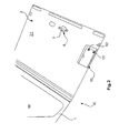
- the embodiment shown in Fig. 2 provides a container of the aforementioned kind with a container door pivotably joinable at a container well's edge, wherein the container is provided with a sensor system adapted to indicate a change of status of the door.
- the container 10 is shown in a cut-out view with the well 1 and the door 2 showing the door's 2 inside surface 2.1.
- the door on its inside surface 2.1 has a locking claw 6 provided with a damping element 7 which allows damped closing and opening of the door 2.
- test openings of the door do not functionality affect the door. and/or the well.
- a trough or the like flat dimple is provided, in particular with a not shown recession or opening, to put through a signaling means.
- an electrical means is provided to collect and process sensoring signals.
- the electrical means like for instance a printed circuit board or the like, forms a node to a network, wherein --by means of the network-- signals of all containers in the cabins are available.
- the printed circuit board can be connected to a sensor system 50 of the container either by means of a physical connection and signaling line or by an air interface between the sensor system 50 and the electrical means in the dimple.
- the sensor system 50 is provided with an opening switch 51 and a motion sensor 52.
- the opening switch is formed as a photo cell which senses the difference between dark and light surrounding conditions. Thus, any --even a small-- gap of opening of the door is sensed by the photocell. However, usually --if not combined with a distance measurement unit-- the photocell of the opening switch 51 will not be able to sense the amount of opening of the door 2 relative to the well.
- a three-axis acceleration sensor is provided as a motion sensor 52.
- the three-axis acceleration sensor is able to sense a moving status of the door.
- the opening switch 51 and the motion sensor 52 both deliver a signaling of a positive response (i.e. some opening and some movement)
- the combination of the signaling can be used to conclude for a complete opening of the door.
- the motion sensor 52 delivers a non-responding signal
- the opening switch 51 delivers a responding signal (i.e. some opening without movement)
- the combination of both signaling can be used to conclude that the door is only partially opened.
- the farther situation can be indicated as a malfunction of the container during all-day use (wherein the correct status would be to have a closed container) and during an emergency situation (wherein an opened container is correct) a respective signaling can be suppressed to avoid superfluous signaling in the aircraft cabin's net.
- the latter signaling usually is indicative of a test position of the container's door relative to the well.
- the latter signaling can be used in a test situation to be indicated as a correct functioning of the container, wherein absence of the signaling or deviating signaling in a test situation should be also indicated as a malfunctioning container.
- a partially opened container should be indicated as a malfunction of the container.
- the container 10 of Fig. 3 has a container well 1 and a container door 2 wherein the container's 10 form and constitution is similar to the container shown in Fig.1 and Fig. 2 ; thus the description of the container 10 in Fig. 1 and Fig. 2 also applies to the container 10 of Fig. 3 .
- the same reference marks are shown with the container 10; nevertheless the containers of Fig.1 , Fig.2 and Fig. 3 respectively may provide differences and adaptations.
- the container 10 is shown without any blends; thus the appearance of facing and colour of the container 10 of Fig. 3 may be different when in an operation position in a row of containers in a ceiling panel.
- the container 10 additionally has a cut solar cell panel foil 8 adapted for conversion of residue light to electrical energy attached on the door's 2 outside surface 2.2.
- the cut size of the panel foil 8 is adapted to the door's 2 margins size.
- the solar cell's electrical outputs are connected together to an energy harvesting unit 9, which provides a battery, a storage capacitor like a super cap or the like electrical energy storage device.
- the connection here provides cable means 18 and a connector 17.
- the system of the solar cell panel foil 8 and the energy harvesting unit 9 provides an energy harvesting device for powering at least the sensor system 50, i.e. at least for powering the opening switch 51 and a motion sensor 52 in a self-sustaining manner. This means sufficient powering is guaranteed in a testing situation and/or emergency situation at least.
- the energy harvesting unit 9, as shown here, is provided in an outer recess 15 of the container well 1 just beneath the container door 2 --respectively (in an operation position of the container 10 as part of a row of containers on a ceiling panel) above the container door 2).
- the harvesting unit 9 also provides for a, preferably, wireless transmitter and control unit 19 for, preferably, wireless control of the energy harvesting unit 9. Also an activation control and safe radio control can be implemented therewith.
- the cable means 18 and connector 17 and harvesting unit 9 and wireless transmitter and control unit 19 can be covered in the recess 15 with a blend (not shown) of the container well 1.
- the cut solar cell panel foil 8 can be put in a suitable frame and light transparent cover which allows for both a secure fitting to the door 2 and an aesthetic face (not shown) when in operation.
- general method for monitoring a container of the aforementioned kind --as shown in Fig. 1 and Fig. 2 -- is depicted in a flowchart of Fig. 4 .
- the flowchart holds for both a test procedure as well as an emergency procedure of use of the container.
- the flowchart is restricted to indicate the sensing signals of the container.
- the conclusions drawn there from depend on the situation --namely a test situation or emergency situation or an all-day use-- the container is in. These and other conclusions can be processed in an application layer, for instance provided in the printed circuit board in the container well's dimple, as outlined above. Additionally or alternatively, a further evaluation --for instance a statistical evaluation of malfunctions or the like-- can be provided in the aircraft cabin's net. Thus, in advance statistical evaluations for a long-term use of the container can be used to indicate risky containers. E.g. in the case when the statistics reveal that a certain container at a certain position in the aircraft's cabin has a number of malfunctioning incidents exceeding a certain threshold such container can be exchanged by a new one.
- step S1 a powering of the container --i.e. the electronics thereof, namely the printed circuit board and the sensor system-- is established to make sure that all electrical components of the container have sufficient power.
- step S2 an initialization of the container electronics and sensor system is provided in form of a functionality check as such of the sensors used. Thus, after step S2, in a test procedure one can be sure that the electronics and sensors of a container 10 are working correctly.
- step S3 an indication of status of the aircraft cabin is provided, namely either a usual operation status, an emergency status or a test status.
- step S4 the status of the opening switch 51 is recalled.
- step S5 the status of the motion sensor 52 is recalled.
- step S6 the door 2 of the container 10 relative to the well 1 is closed.
- step S7 In the case the opening switch 51 is in a responding state and the motion sensor 52 is in a non-responding state, it can be concluded in step S7 that the door is partially open as described above.
- step S8 a complete opening of the door can be signalized in the case the opening switch 51 and the motion sensor 52 is in a responding state.
- the accumulation of YES or NO signaling, as indicated in the branches from steps S4 and S5 to steps S7, S8, S6, can be provided in an electronic circuit board or the like electronics 60 e.g. placed in a dimple or trough or the like, in the floor 1.5 of the container's well 1.
- the statistics and/or in advance warnings for a container's malfunction can be centrally processed in a cabin's network processor or the like.
Priority Applications (4)
| Application Number | Priority Date | Filing Date | Title |
|---|---|---|---|
| EP13167630.6A EP2679500B1 (de) | 2012-06-28 | 2013-05-14 | Behälter für eine Sauerstoffversorgungseinheit, Vorrichtung und System einer Anordnung mehrerer Sauerstoffversorgungsvorrichtungen, wobei jede Sauerstoffversorgungseinheit in einem Behälter gelagert ist, Verfahren zur Steuerung eines Status und/oder eines Statuswechsels eines Behälters |
| CA2820506A CA2820506C (en) | 2012-06-28 | 2013-06-18 | Container for an oxygen supply unit and system of a plurality of oxygen supply devices, adapted to indicate a status or status change |
| CN201310269572.5A CN103523227B (zh) | 2012-06-28 | 2013-06-28 | 用于供氧单元的容器、布置多个供氧设备的系统及控制容器状态和/或状态改变的方法 |
| BR102013016882-3A BR102013016882B1 (pt) | 2012-06-28 | 2013-06-28 | Contêiner para uma unidade de fornecimento de oxigênio, sistema compreendendo um contêiner e um dispositivo de fornecimento de oxigênio, sistema compreendendo um conjunto de contêineres e método de monitoramento de uma alteração de estado de um contêiner |
Applications Claiming Priority (2)
| Application Number | Priority Date | Filing Date | Title |
|---|---|---|---|
| EP12174223 | 2012-06-28 | ||
| EP13167630.6A EP2679500B1 (de) | 2012-06-28 | 2013-05-14 | Behälter für eine Sauerstoffversorgungseinheit, Vorrichtung und System einer Anordnung mehrerer Sauerstoffversorgungsvorrichtungen, wobei jede Sauerstoffversorgungseinheit in einem Behälter gelagert ist, Verfahren zur Steuerung eines Status und/oder eines Statuswechsels eines Behälters |
Publications (3)
| Publication Number | Publication Date |
|---|---|
| EP2679500A2 true EP2679500A2 (de) | 2014-01-01 |
| EP2679500A3 EP2679500A3 (de) | 2016-03-09 |
| EP2679500B1 EP2679500B1 (de) | 2018-04-11 |
Family
ID=48463755
Family Applications (1)
| Application Number | Title | Priority Date | Filing Date |
|---|---|---|---|
| EP13167630.6A Active EP2679500B1 (de) | 2012-06-28 | 2013-05-14 | Behälter für eine Sauerstoffversorgungseinheit, Vorrichtung und System einer Anordnung mehrerer Sauerstoffversorgungsvorrichtungen, wobei jede Sauerstoffversorgungseinheit in einem Behälter gelagert ist, Verfahren zur Steuerung eines Status und/oder eines Statuswechsels eines Behälters |
Country Status (4)
| Country | Link |
|---|---|
| EP (1) | EP2679500B1 (de) |
| CN (1) | CN103523227B (de) |
| BR (1) | BR102013016882B1 (de) |
| CA (1) | CA2820506C (de) |
Cited By (1)
| Publication number | Priority date | Publication date | Assignee | Title |
|---|---|---|---|---|
| CN105737789A (zh) * | 2016-02-06 | 2016-07-06 | 苏州同优信息科技有限公司 | 一种上下开合式钱包的打开检测方法 |
Families Citing this family (1)
| Publication number | Priority date | Publication date | Assignee | Title |
|---|---|---|---|---|
| CN107512398B (zh) * | 2017-08-25 | 2023-03-28 | 国网电力空间技术有限公司 | 用于直升机的氧气设备固定装置及其安装方法 |
Family Cites Families (4)
| Publication number | Priority date | Publication date | Assignee | Title |
|---|---|---|---|---|
| US3615250A (en) * | 1969-03-26 | 1971-10-26 | Lockheed Aircraft Corp | Supplemental oxygen supply system |
| IL200050A0 (en) * | 2008-08-07 | 2010-04-29 | Stanley Works Israel | Tool container with an alarm system |
| US20120041619A1 (en) * | 2008-08-25 | 2012-02-16 | Grenfell Saxon Rudduck | System for Aircraft |
| GB2480322B (en) * | 2010-05-14 | 2013-04-24 | Tool Control Systems Ltd | Inventory storage apparatus and inventory item verification process |
-
2013
- 2013-05-14 EP EP13167630.6A patent/EP2679500B1/de active Active
- 2013-06-18 CA CA2820506A patent/CA2820506C/en active Active
- 2013-06-28 CN CN201310269572.5A patent/CN103523227B/zh active Active
- 2013-06-28 BR BR102013016882-3A patent/BR102013016882B1/pt active IP Right Grant
Non-Patent Citations (1)
| Title |
|---|
| None |
Cited By (1)
| Publication number | Priority date | Publication date | Assignee | Title |
|---|---|---|---|---|
| CN105737789A (zh) * | 2016-02-06 | 2016-07-06 | 苏州同优信息科技有限公司 | 一种上下开合式钱包的打开检测方法 |
Also Published As
| Publication number | Publication date |
|---|---|
| CA2820506C (en) | 2019-07-16 |
| CN103523227A (zh) | 2014-01-22 |
| EP2679500B1 (de) | 2018-04-11 |
| CA2820506A1 (en) | 2013-12-28 |
| EP2679500A3 (de) | 2016-03-09 |
| BR102013016882A2 (pt) | 2015-08-25 |
| CN103523227B (zh) | 2018-03-27 |
| BR102013016882B1 (pt) | 2021-11-03 |
Similar Documents
| Publication | Publication Date | Title |
|---|---|---|
| US9988150B2 (en) | Container for an oxygen supply unit, device and system of an arrangement of a number of oxygen supply devices, wherein each oxygen supply unit is stored in a container, method of control of a status and/or change of status of a container | |
| US8149140B2 (en) | Pressure-difference warning system | |
| CN105947226B (zh) | 一种旋翼式无人机智能失控保护系统及其保护方法 | |
| EP3159266B1 (de) | Anzeigeeinrichtung zum anzeigen eines aktivierungsstatus einer notrutsche in einem flugzeug | |
| US6824175B2 (en) | Device for indicating incorrect closure of locking means located between two fan cowlings of an aircraft engine nacelle | |
| CN204368136U (zh) | 汽车火灾紧急控制系统 | |
| EP2679500B1 (de) | Behälter für eine Sauerstoffversorgungseinheit, Vorrichtung und System einer Anordnung mehrerer Sauerstoffversorgungsvorrichtungen, wobei jede Sauerstoffversorgungseinheit in einem Behälter gelagert ist, Verfahren zur Steuerung eines Status und/oder eines Statuswechsels eines Behälters | |
| CA2660065C (en) | A storage box for a respiratory mask to be worn by crewmembers of an aircraft | |
| CN206885363U (zh) | 无人机缓速多重保护装置 | |
| CN106347643A (zh) | 一种无人机自动保护系统 | |
| US10228299B2 (en) | Systems and methods for monitoring operative components of a vehicle based on ambient conditions | |
| CN102933460B (zh) | 用于在水上降落期间控制飞机部件的方法和系统 | |
| EP3133018A1 (de) | Anzeigeeinrichtung sowie türanordnung und flugzeug mit einer solchen anzeigeeinrichtung | |
| EP3065117B1 (de) | Doppelschleifen-rauch- und feuerdetektorsystem und verfahren | |
| JP4483925B2 (ja) | 衝突判定装置、及び乗員保護装置 | |
| CN205239192U (zh) | 一种儿童座椅安全检测系统及汽车 | |
| US20080092630A1 (en) | Pressure sensor device | |
| EP2993125B1 (de) | System zur Erkennung einer Druckdifferenz zwischen dem Inneren und dem Äußeren eines Flugzeugs | |
| US8466788B2 (en) | Device and method for protection against intrusion into the landing gear housing of aircraft | |
| EP2990328B1 (de) | Verfahren zur unterscheidung zwischen dem flugstatus und dem bodenstatus eines flugzeugs | |
| CN206664240U (zh) | 一种客车用应急安全门 | |
| CN209702040U (zh) | 一种电梯监控器 | |
| EP3653417A1 (de) | Notfallsystem in einem fahrzeug | |
| Zhong et al. | Research on helicopter water-landing monitoring technology | |
| CN201553301U (zh) | 直升机桨叶触发报警系统 |
Legal Events
| Date | Code | Title | Description |
|---|---|---|---|
| PUAI | Public reference made under article 153(3) epc to a published international application that has entered the european phase |
Free format text: ORIGINAL CODE: 0009012 |
|
| AK | Designated contracting states |
Kind code of ref document: A2 Designated state(s): AL AT BE BG CH CY CZ DE DK EE ES FI FR GB GR HR HU IE IS IT LI LT LU LV MC MK MT NL NO PL PT RO RS SE SI SK SM TR |
|
| AX | Request for extension of the european patent |
Extension state: BA ME |
|
| RAP1 | Party data changed (applicant data changed or rights of an application transferred) |
Owner name: ZODIAC AEROTECHNICS |
|
| PUAL | Search report despatched |
Free format text: ORIGINAL CODE: 0009013 |
|
| AK | Designated contracting states |
Kind code of ref document: A3 Designated state(s): AL AT BE BG CH CY CZ DE DK EE ES FI FR GB GR HR HU IE IS IT LI LT LU LV MC MK MT NL NO PL PT RO RS SE SI SK SM TR |
|
| AX | Request for extension of the european patent |
Extension state: BA ME |
|
| RIC1 | Information provided on ipc code assigned before grant |
Ipc: B64D 25/00 20060101AFI20160203BHEP Ipc: B64D 13/00 20060101ALI20160203BHEP Ipc: B64D 11/06 20060101ALI20160203BHEP Ipc: B64D 11/00 20060101ALI20160203BHEP |
|
| 17P | Request for examination filed |
Effective date: 20160909 |
|
| RBV | Designated contracting states (corrected) |
Designated state(s): AL AT BE BG CH CY CZ DE DK EE ES FI FR GB GR HR HU IE IS IT LI LT LU LV MC MK MT NL NO PL PT RO RS SE SI SK SM TR |
|
| 17Q | First examination report despatched |
Effective date: 20170518 |
|
| GRAP | Despatch of communication of intention to grant a patent |
Free format text: ORIGINAL CODE: EPIDOSNIGR1 |
|
| INTG | Intention to grant announced |
Effective date: 20171030 |
|
| GRAS | Grant fee paid |
Free format text: ORIGINAL CODE: EPIDOSNIGR3 |
|
| GRAA | (expected) grant |
Free format text: ORIGINAL CODE: 0009210 |
|
| REG | Reference to a national code |
Ref country code: FR Ref legal event code: PLFP Year of fee payment: 6 |
|
| AK | Designated contracting states |
Kind code of ref document: B1 Designated state(s): AL AT BE BG CH CY CZ DE DK EE ES FI FR GB GR HR HU IE IS IT LI LT LU LV MC MK MT NL NO PL PT RO RS SE SI SK SM TR |
|
| REG | Reference to a national code |
Ref country code: GB Ref legal event code: FG4D |
|
| REG | Reference to a national code |
Ref country code: CH Ref legal event code: EP |
|
| REG | Reference to a national code |
Ref country code: AT Ref legal event code: REF Ref document number: 987755 Country of ref document: AT Kind code of ref document: T Effective date: 20180415 |
|
| REG | Reference to a national code |
Ref country code: IE Ref legal event code: FG4D |
|
| REG | Reference to a national code |
Ref country code: DE Ref legal event code: R096 Ref document number: 602013035623 Country of ref document: DE |
|
| REG | Reference to a national code |
Ref country code: NL Ref legal event code: MP Effective date: 20180411 |
|
| REG | Reference to a national code |
Ref country code: LT Ref legal event code: MG4D |
|
| PG25 | Lapsed in a contracting state [announced via postgrant information from national office to epo] |
Ref country code: NL Free format text: LAPSE BECAUSE OF FAILURE TO SUBMIT A TRANSLATION OF THE DESCRIPTION OR TO PAY THE FEE WITHIN THE PRESCRIBED TIME-LIMIT Effective date: 20180411 |
|
| PG25 | Lapsed in a contracting state [announced via postgrant information from national office to epo] |
Ref country code: NO Free format text: LAPSE BECAUSE OF FAILURE TO SUBMIT A TRANSLATION OF THE DESCRIPTION OR TO PAY THE FEE WITHIN THE PRESCRIBED TIME-LIMIT Effective date: 20180711 Ref country code: LT Free format text: LAPSE BECAUSE OF FAILURE TO SUBMIT A TRANSLATION OF THE DESCRIPTION OR TO PAY THE FEE WITHIN THE PRESCRIBED TIME-LIMIT Effective date: 20180411 Ref country code: FI Free format text: LAPSE BECAUSE OF FAILURE TO SUBMIT A TRANSLATION OF THE DESCRIPTION OR TO PAY THE FEE WITHIN THE PRESCRIBED TIME-LIMIT Effective date: 20180411 Ref country code: BG Free format text: LAPSE BECAUSE OF FAILURE TO SUBMIT A TRANSLATION OF THE DESCRIPTION OR TO PAY THE FEE WITHIN THE PRESCRIBED TIME-LIMIT Effective date: 20180711 Ref country code: AL Free format text: LAPSE BECAUSE OF FAILURE TO SUBMIT A TRANSLATION OF THE DESCRIPTION OR TO PAY THE FEE WITHIN THE PRESCRIBED TIME-LIMIT Effective date: 20180411 Ref country code: ES Free format text: LAPSE BECAUSE OF FAILURE TO SUBMIT A TRANSLATION OF THE DESCRIPTION OR TO PAY THE FEE WITHIN THE PRESCRIBED TIME-LIMIT Effective date: 20180411 Ref country code: SE Free format text: LAPSE BECAUSE OF FAILURE TO SUBMIT A TRANSLATION OF THE DESCRIPTION OR TO PAY THE FEE WITHIN THE PRESCRIBED TIME-LIMIT Effective date: 20180411 Ref country code: PL Free format text: LAPSE BECAUSE OF FAILURE TO SUBMIT A TRANSLATION OF THE DESCRIPTION OR TO PAY THE FEE WITHIN THE PRESCRIBED TIME-LIMIT Effective date: 20180411 |
|
| PG25 | Lapsed in a contracting state [announced via postgrant information from national office to epo] |
Ref country code: LV Free format text: LAPSE BECAUSE OF FAILURE TO SUBMIT A TRANSLATION OF THE DESCRIPTION OR TO PAY THE FEE WITHIN THE PRESCRIBED TIME-LIMIT Effective date: 20180411 Ref country code: HR Free format text: LAPSE BECAUSE OF FAILURE TO SUBMIT A TRANSLATION OF THE DESCRIPTION OR TO PAY THE FEE WITHIN THE PRESCRIBED TIME-LIMIT Effective date: 20180411 Ref country code: GR Free format text: LAPSE BECAUSE OF FAILURE TO SUBMIT A TRANSLATION OF THE DESCRIPTION OR TO PAY THE FEE WITHIN THE PRESCRIBED TIME-LIMIT Effective date: 20180712 Ref country code: RS Free format text: LAPSE BECAUSE OF FAILURE TO SUBMIT A TRANSLATION OF THE DESCRIPTION OR TO PAY THE FEE WITHIN THE PRESCRIBED TIME-LIMIT Effective date: 20180411 |
|
| REG | Reference to a national code |
Ref country code: CH Ref legal event code: PL |
|
| REG | Reference to a national code |
Ref country code: AT Ref legal event code: MK05 Ref document number: 987755 Country of ref document: AT Kind code of ref document: T Effective date: 20180411 |
|
| PG25 | Lapsed in a contracting state [announced via postgrant information from national office to epo] |
Ref country code: PT Free format text: LAPSE BECAUSE OF FAILURE TO SUBMIT A TRANSLATION OF THE DESCRIPTION OR TO PAY THE FEE WITHIN THE PRESCRIBED TIME-LIMIT Effective date: 20180813 |
|
| REG | Reference to a national code |
Ref country code: DE Ref legal event code: R097 Ref document number: 602013035623 Country of ref document: DE |
|
| REG | Reference to a national code |
Ref country code: BE Ref legal event code: MM Effective date: 20180531 |
|
| PG25 | Lapsed in a contracting state [announced via postgrant information from national office to epo] |
Ref country code: DK Free format text: LAPSE BECAUSE OF FAILURE TO SUBMIT A TRANSLATION OF THE DESCRIPTION OR TO PAY THE FEE WITHIN THE PRESCRIBED TIME-LIMIT Effective date: 20180411 Ref country code: AT Free format text: LAPSE BECAUSE OF FAILURE TO SUBMIT A TRANSLATION OF THE DESCRIPTION OR TO PAY THE FEE WITHIN THE PRESCRIBED TIME-LIMIT Effective date: 20180411 Ref country code: EE Free format text: LAPSE BECAUSE OF FAILURE TO SUBMIT A TRANSLATION OF THE DESCRIPTION OR TO PAY THE FEE WITHIN THE PRESCRIBED TIME-LIMIT Effective date: 20180411 Ref country code: CZ Free format text: LAPSE BECAUSE OF FAILURE TO SUBMIT A TRANSLATION OF THE DESCRIPTION OR TO PAY THE FEE WITHIN THE PRESCRIBED TIME-LIMIT Effective date: 20180411 Ref country code: RO Free format text: LAPSE BECAUSE OF FAILURE TO SUBMIT A TRANSLATION OF THE DESCRIPTION OR TO PAY THE FEE WITHIN THE PRESCRIBED TIME-LIMIT Effective date: 20180411 Ref country code: SK Free format text: LAPSE BECAUSE OF FAILURE TO SUBMIT A TRANSLATION OF THE DESCRIPTION OR TO PAY THE FEE WITHIN THE PRESCRIBED TIME-LIMIT Effective date: 20180411 Ref country code: MC Free format text: LAPSE BECAUSE OF FAILURE TO SUBMIT A TRANSLATION OF THE DESCRIPTION OR TO PAY THE FEE WITHIN THE PRESCRIBED TIME-LIMIT Effective date: 20180411 |
|
| PLBE | No opposition filed within time limit |
Free format text: ORIGINAL CODE: 0009261 |
|
| STAA | Information on the status of an ep patent application or granted ep patent |
Free format text: STATUS: NO OPPOSITION FILED WITHIN TIME LIMIT |
|
| REG | Reference to a national code |
Ref country code: IE Ref legal event code: MM4A |
|
| PG25 | Lapsed in a contracting state [announced via postgrant information from national office to epo] |
Ref country code: SM Free format text: LAPSE BECAUSE OF FAILURE TO SUBMIT A TRANSLATION OF THE DESCRIPTION OR TO PAY THE FEE WITHIN THE PRESCRIBED TIME-LIMIT Effective date: 20180411 Ref country code: IT Free format text: LAPSE BECAUSE OF FAILURE TO SUBMIT A TRANSLATION OF THE DESCRIPTION OR TO PAY THE FEE WITHIN THE PRESCRIBED TIME-LIMIT Effective date: 20180411 Ref country code: CH Free format text: LAPSE BECAUSE OF NON-PAYMENT OF DUE FEES Effective date: 20180531 Ref country code: LI Free format text: LAPSE BECAUSE OF NON-PAYMENT OF DUE FEES Effective date: 20180531 |
|
| 26N | No opposition filed |
Effective date: 20190114 |
|
| GBPC | Gb: european patent ceased through non-payment of renewal fee |
Effective date: 20180711 |
|
| PG25 | Lapsed in a contracting state [announced via postgrant information from national office to epo] |
Ref country code: LU Free format text: LAPSE BECAUSE OF NON-PAYMENT OF DUE FEES Effective date: 20180514 |
|
| PG25 | Lapsed in a contracting state [announced via postgrant information from national office to epo] |
Ref country code: GB Free format text: LAPSE BECAUSE OF NON-PAYMENT OF DUE FEES Effective date: 20180711 Ref country code: IE Free format text: LAPSE BECAUSE OF NON-PAYMENT OF DUE FEES Effective date: 20180514 |
|
| PG25 | Lapsed in a contracting state [announced via postgrant information from national office to epo] |
Ref country code: SI Free format text: LAPSE BECAUSE OF FAILURE TO SUBMIT A TRANSLATION OF THE DESCRIPTION OR TO PAY THE FEE WITHIN THE PRESCRIBED TIME-LIMIT Effective date: 20180411 Ref country code: BE Free format text: LAPSE BECAUSE OF NON-PAYMENT OF DUE FEES Effective date: 20180531 |
|
| PG25 | Lapsed in a contracting state [announced via postgrant information from national office to epo] |
Ref country code: MT Free format text: LAPSE BECAUSE OF NON-PAYMENT OF DUE FEES Effective date: 20180514 |
|
| PG25 | Lapsed in a contracting state [announced via postgrant information from national office to epo] |
Ref country code: TR Free format text: LAPSE BECAUSE OF FAILURE TO SUBMIT A TRANSLATION OF THE DESCRIPTION OR TO PAY THE FEE WITHIN THE PRESCRIBED TIME-LIMIT Effective date: 20180411 |
|
| PG25 | Lapsed in a contracting state [announced via postgrant information from national office to epo] |
Ref country code: HU Free format text: LAPSE BECAUSE OF FAILURE TO SUBMIT A TRANSLATION OF THE DESCRIPTION OR TO PAY THE FEE WITHIN THE PRESCRIBED TIME-LIMIT; INVALID AB INITIO Effective date: 20130514 |
|
| PG25 | Lapsed in a contracting state [announced via postgrant information from national office to epo] |
Ref country code: CY Free format text: LAPSE BECAUSE OF FAILURE TO SUBMIT A TRANSLATION OF THE DESCRIPTION OR TO PAY THE FEE WITHIN THE PRESCRIBED TIME-LIMIT Effective date: 20180411 Ref country code: MK Free format text: LAPSE BECAUSE OF NON-PAYMENT OF DUE FEES Effective date: 20180411 |
|
| PG25 | Lapsed in a contracting state [announced via postgrant information from national office to epo] |
Ref country code: IS Free format text: LAPSE BECAUSE OF FAILURE TO SUBMIT A TRANSLATION OF THE DESCRIPTION OR TO PAY THE FEE WITHIN THE PRESCRIBED TIME-LIMIT Effective date: 20180811 |
|
| REG | Reference to a national code |
Ref country code: DE Ref legal event code: R081 Ref document number: 602013035623 Country of ref document: DE Owner name: SAFRAN AEROTECHNICS S.A.S., FR Free format text: FORMER OWNER: ZODIAC AEROTECHNICS, PLAISIR, FR |
|
| PGFP | Annual fee paid to national office [announced via postgrant information from national office to epo] |
Ref country code: FR Payment date: 20230420 Year of fee payment: 11 Ref country code: DE Payment date: 20230419 Year of fee payment: 11 |