EP2679185A1 - Surgical forceps - Google Patents
Surgical forceps Download PDFInfo
- Publication number
- EP2679185A1 EP2679185A1 EP20130174296 EP13174296A EP2679185A1 EP 2679185 A1 EP2679185 A1 EP 2679185A1 EP 20130174296 EP20130174296 EP 20130174296 EP 13174296 A EP13174296 A EP 13174296A EP 2679185 A1 EP2679185 A1 EP 2679185A1
- Authority
- EP
- European Patent Office
- Prior art keywords
- end effector
- effector assembly
- monopolar
- tissue
- tubular member
- Prior art date
- Legal status (The legal status is an assumption and is not a legal conclusion. Google has not performed a legal analysis and makes no representation as to the accuracy of the status listed.)
- Granted
Links
Images



Classifications
-
- A—HUMAN NECESSITIES
- A61—MEDICAL OR VETERINARY SCIENCE; HYGIENE
- A61B—DIAGNOSIS; SURGERY; IDENTIFICATION
- A61B18/00—Surgical instruments, devices or methods for transferring non-mechanical forms of energy to or from the body
- A61B18/04—Surgical instruments, devices or methods for transferring non-mechanical forms of energy to or from the body by heating
- A61B18/12—Surgical instruments, devices or methods for transferring non-mechanical forms of energy to or from the body by heating by passing a current through the tissue to be heated, e.g. high-frequency current
- A61B18/14—Probes or electrodes therefor
- A61B18/1442—Probes having pivoting end effectors, e.g. forceps
- A61B18/1445—Probes having pivoting end effectors, e.g. forceps at the distal end of a shaft, e.g. forceps or scissors at the end of a rigid rod
-
- A—HUMAN NECESSITIES
- A61—MEDICAL OR VETERINARY SCIENCE; HYGIENE
- A61B—DIAGNOSIS; SURGERY; IDENTIFICATION
- A61B18/00—Surgical instruments, devices or methods for transferring non-mechanical forms of energy to or from the body
- A61B2018/00571—Surgical instruments, devices or methods for transferring non-mechanical forms of energy to or from the body for achieving a particular surgical effect
- A61B2018/00601—Cutting
-
- A—HUMAN NECESSITIES
- A61—MEDICAL OR VETERINARY SCIENCE; HYGIENE
- A61B—DIAGNOSIS; SURGERY; IDENTIFICATION
- A61B18/00—Surgical instruments, devices or methods for transferring non-mechanical forms of energy to or from the body
- A61B2018/00571—Surgical instruments, devices or methods for transferring non-mechanical forms of energy to or from the body for achieving a particular surgical effect
- A61B2018/0063—Sealing
-
- A—HUMAN NECESSITIES
- A61—MEDICAL OR VETERINARY SCIENCE; HYGIENE
- A61B—DIAGNOSIS; SURGERY; IDENTIFICATION
- A61B18/00—Surgical instruments, devices or methods for transferring non-mechanical forms of energy to or from the body
- A61B18/04—Surgical instruments, devices or methods for transferring non-mechanical forms of energy to or from the body by heating
- A61B18/12—Surgical instruments, devices or methods for transferring non-mechanical forms of energy to or from the body by heating by passing a current through the tissue to be heated, e.g. high-frequency current
- A61B18/1206—Generators therefor
- A61B2018/1246—Generators therefor characterised by the output polarity
- A61B2018/1253—Generators therefor characterised by the output polarity monopolar
-
- A—HUMAN NECESSITIES
- A61—MEDICAL OR VETERINARY SCIENCE; HYGIENE
- A61B—DIAGNOSIS; SURGERY; IDENTIFICATION
- A61B18/00—Surgical instruments, devices or methods for transferring non-mechanical forms of energy to or from the body
- A61B18/04—Surgical instruments, devices or methods for transferring non-mechanical forms of energy to or from the body by heating
- A61B18/12—Surgical instruments, devices or methods for transferring non-mechanical forms of energy to or from the body by heating by passing a current through the tissue to be heated, e.g. high-frequency current
- A61B18/1206—Generators therefor
- A61B2018/1246—Generators therefor characterised by the output polarity
- A61B2018/126—Generators therefor characterised by the output polarity bipolar
-
- A—HUMAN NECESSITIES
- A61—MEDICAL OR VETERINARY SCIENCE; HYGIENE
- A61B—DIAGNOSIS; SURGERY; IDENTIFICATION
- A61B18/00—Surgical instruments, devices or methods for transferring non-mechanical forms of energy to or from the body
- A61B18/04—Surgical instruments, devices or methods for transferring non-mechanical forms of energy to or from the body by heating
- A61B18/12—Surgical instruments, devices or methods for transferring non-mechanical forms of energy to or from the body by heating by passing a current through the tissue to be heated, e.g. high-frequency current
- A61B18/14—Probes or electrodes therefor
- A61B2018/1405—Electrodes having a specific shape
- A61B2018/1422—Hook
-
- A—HUMAN NECESSITIES
- A61—MEDICAL OR VETERINARY SCIENCE; HYGIENE
- A61B—DIAGNOSIS; SURGERY; IDENTIFICATION
- A61B18/00—Surgical instruments, devices or methods for transferring non-mechanical forms of energy to or from the body
- A61B18/04—Surgical instruments, devices or methods for transferring non-mechanical forms of energy to or from the body by heating
- A61B18/12—Surgical instruments, devices or methods for transferring non-mechanical forms of energy to or from the body by heating by passing a current through the tissue to be heated, e.g. high-frequency current
- A61B18/14—Probes or electrodes therefor
- A61B18/1442—Probes having pivoting end effectors, e.g. forceps
- A61B2018/1452—Probes having pivoting end effectors, e.g. forceps including means for cutting
- A61B2018/1455—Probes having pivoting end effectors, e.g. forceps including means for cutting having a moving blade for cutting tissue grasped by the jaws
-
- A—HUMAN NECESSITIES
- A61—MEDICAL OR VETERINARY SCIENCE; HYGIENE
- A61B—DIAGNOSIS; SURGERY; IDENTIFICATION
- A61B18/00—Surgical instruments, devices or methods for transferring non-mechanical forms of energy to or from the body
- A61B18/04—Surgical instruments, devices or methods for transferring non-mechanical forms of energy to or from the body by heating
- A61B18/12—Surgical instruments, devices or methods for transferring non-mechanical forms of energy to or from the body by heating by passing a current through the tissue to be heated, e.g. high-frequency current
- A61B18/14—Probes or electrodes therefor
- A61B2018/1467—Probes or electrodes therefor using more than two electrodes on a single probe
-
- A—HUMAN NECESSITIES
- A61—MEDICAL OR VETERINARY SCIENCE; HYGIENE
- A61B—DIAGNOSIS; SURGERY; IDENTIFICATION
- A61B18/00—Surgical instruments, devices or methods for transferring non-mechanical forms of energy to or from the body
- A61B18/04—Surgical instruments, devices or methods for transferring non-mechanical forms of energy to or from the body by heating
- A61B18/12—Surgical instruments, devices or methods for transferring non-mechanical forms of energy to or from the body by heating by passing a current through the tissue to be heated, e.g. high-frequency current
- A61B18/14—Probes or electrodes therefor
- A61B2018/1475—Electrodes retractable in or deployable from a housing
Definitions
- proximal flanges of the jaw members are pivotally arranged together. They may cooperate to define a lumen therethrough.
- the monopolar member may translate through the lumen between the first and second positions.
- the distal tip may be disposed in the lumen in the first position.
- a method of treating tissue includes grasping tissue between first and second jaw members, treating tissue grasped between the first and second jaw members, deploying an insulative tubular member about the first and second jaw members, deploying a monopolar member such that a distal tip of the monopolar member extends distally from the end effector assembly and the insulative tubular member, and treating tissue adjacent the distal tip of the monopolar member.
- the step of treating tissue grasped between the first and second jaw members includes applying energy between the first and second jaw members and through tissue grasped therebetween. Further, the step of treating tissue adjacent the distal tip of the monopolar member may include applying energy from distal tip to tissue adjacent the distal tip.
- Fig. 6D is side, perspective view of another end effector assembly configured for use with the forceps of Fig. 1 and shown with parts separated, the end effector assembly including a monopolar assembly disposed in a retracted position;
- Fig. 6E is a top, perspective view of another end effector assembly configured for use with the forceps of Fig. 1 shown including a monopolar assembly disposed in an extended position;
- Fig. 6F is a bottom, perspective view of the end effector assembly of Fig. 6E shown including the monopolar assembly disposed in a retracted position;
- second activation switch 95 may be actuated to supply energy to inner tubular member 220 such that energy is conducted along inner tubular member 220 to distal tip 224 thereof, and from distal tip 224 to tissue to treat, e.g., dissect, tissue.
- energy is returned via a remotely positioned return pad (not explicitly shown).
- forceps 10 may be moved relative to tissue, e.g., longittadinally along longitudinal axis "X-X" and/or radially therefrom, to facilitate electromechanical treatment of tissue.
- forceps 10 may be moved relative to tissue to facilitate mechanically dissecting tissue, e.g., scoring tissue planes, with distal tip 224 in the absence of energy being applied to distal tip 224.
- monopolar assembly 200 may be returned to the retracted position ( Figs. 4A-4B ), e.g., via translating slide knob 64 of slide assembly 60 proximally along slot 22 to proximal end 23 thereof.
- jaw members 110, 120 of end effector assembly 100 may be manipulated to grasp, treat, and/or cut tissue, as described above, in the bipolar mode.
- outer tubular member 310 and rod member 320 may be coupled to one another to effect simultaneous but differential deployment of outer tubular member 310 and rod member 320 relative to one another, or may be independent of one another such that outer tubular member 310 and/or rod member 320 may be selectively deployed independently of one another.
Landscapes
- Health & Medical Sciences (AREA)
- Surgery (AREA)
- Engineering & Computer Science (AREA)
- Life Sciences & Earth Sciences (AREA)
- Biomedical Technology (AREA)
- Otolaryngology (AREA)
- Nuclear Medicine, Radiotherapy & Molecular Imaging (AREA)
- Plasma & Fusion (AREA)
- Physics & Mathematics (AREA)
- Heart & Thoracic Surgery (AREA)
- Medical Informatics (AREA)
- Molecular Biology (AREA)
- Animal Behavior & Ethology (AREA)
- General Health & Medical Sciences (AREA)
- Public Health (AREA)
- Veterinary Medicine (AREA)
- Surgical Instruments (AREA)
Abstract
Description
- The present disclosure relates to surgical instruments and, more particularly, to a bipolar surgical forceps including an extendable monopolar element.
- Bipolar electrosurgical forceps typically include two generally opposing electrodes charged to different electric potentials to selectively apply energy to tissue. Bipolar electrosurgical forceps utilize both mechanical clamping action and electrical energy to effect hemostasis by heating tissue and blood vessels to coagulate and/or cauterize tissue. Certain surgical procedures require more than simply cauterizing tissue and rely on the unique combination of clamping pressure, precise electrosurgical energy control and gap distance (i.e., distance between opposing jaw members when closed about tissue) to "seal" tissue, vessels and certain vascular bundles. Typically, once a vessel is sealed, the surgeon has to accurately sever the vessel along the newly formed tissue seal. Accordingly, many forceps have been designed which incorporate a knife or blade member that effectively severs the tissue after forming a tissue seal.
- Monopolar surgical instruments, on the other hand, include an active electrode, and are used in conjunction with a remote return electrode, e.g., a return pad, to apply energy to tissue. Monopolar instruments have the ability to rapidly move through tissue and dissect through narrow tissue planes.
- In some surgical procedures, it may be beneficial to use both bipolar and monopolar instrumentation, e.g., procedures where it is necessary to dissect through one or more layers of tissue in order to reach underlying tissue(s) to be sealed. Further, it may be beneficial, particularly with respect to endoscopic surgical procedures, to provide a singe instrument incorporating both bipolar and monopolar features, thereby obviating the need to alternatingly remove and insert the bipolar and monopolar instruments in favor of one another.
- As used herein, the term "distal" refers to the portion that is being described which is further from a user, while the term "proximal" refers to the portion that is being described which is closer to a user. Further, to the extent consistent, any of the aspects described herein may be used in conjunction with any of the other aspects described herein.
- In accordance with aspects of the present disclosure, a forceps is provided including an end effector assembly having first and second jaw members configured to grasp tissue therebetween and conduct energy through tissue grasped therebetween to treat tissue. An insulative tubular member is movable relative to the end effector assembly between a retracted position, wherein the insulative tubular member is positioned proximally of the end effector assembly, and an extended position, wherein the insulative tubular member is disposed about the end effector assembly. A monopolar member is selectively deployable relative to the end effector assembly from a first position to a second position. In the second position, a portion of the monopolar member extends distally from the end effector assembly and the insulative tubular member for applying energy to tissue to treat tissue.
- In one aspect, the monopolar member includes an elongated rod member having an electrically-conductive distal tip. The electrically-conductive distal tip is configured to extend distally from the end effector assembly and the insulative tubular member when disposed in the second position.
- In another aspect, the distal tip is disposed within a longitudinal lumen extending through a distal jaw housing of one of the jaw members when in the first position.
- In another aspect, the distal tip is disposed within a recess defined within a distal jaw housing of one of the jaw members when in the first position.
- In still another aspect, the distal tip is disposed within a recess defined within a proximal flange portion of one of the jaw members when in the first position.
- In yet another aspect, the distal tip is disposed within an insulative sleeve positioned proximally of the end effector assembly when in the first position.
- In still yet another aspect, the electrically-conductive distal tip defines a hook-shaped configuration.
- In another aspect, one of the jaw members defines a cut-out configured to receive a portion of the monopolar member when the monopolar member is disposed in the second position.
- In yet another aspect, the insulative tubular member and the monopolar member are coupled to one another such that, as the insulative tubular member is moved between the retracted position and the extended position, the monopolar member is moved between the first position and the second position. Alternatively, the insulative tubular member and the monopolar member may be independently movable relative to one another.
- Another forceps provided in accordance with aspects of the present disclosure includes an end effector assembly having first and second jaw members configured to grasp tissue therebetween and conduct energy through tissue grasped therebetween to treat tissue. An insulative tubular member is movable relative to the end effector assembly between a retracted position, wherein the insulative tubular member is positioned proximally of the end effector assembly, and an extended position, wherein the insulative tubular member is disposed about the end effector assembly. An elongated rod member having an electrically-conductive distal tip is also provided. The rod member is selectively deployable relative to the end effector assembly from a first position, wherein the distal tip is disposed proximally of the end effector assembly, to a second position, wherein the distal tip extends distally from the end effector assembly and the insulative tubular member for applying energy to tissue to treat tissue.
- In one aspect, in the second position, the elongated rod member extends alongside the end effector assembly and the distal tip extends distally from the end effector assembly.
- In another aspect, the jaw members define a curved configuration. More specifically, in such an aspect, the jaw members curve towards the elongated rod member such that a portion of one of the jaw members extends into a travel path of the elongated rod member. The jaw members defines a cut-out configured to receive the elongated rod member to permit movement of the elongated rod member between the first and second positions.
- In yet another aspect, each jaw member includes a distal jaw portion and a proximal flange. The proximal flange of one of the jaw members defining a recess configured to receive the distal tip when the elongated rod member is disposed in the first position.
- In still another aspect, in the first position, the distal tip is disposed within an insulative sleeve positioned proximally of the end effector assembly.
- In another aspect, the insulative tubular member and the elongated rod member are coupled to one another such that, as the insulative tubular member is moved between the retracted position and the extended position, the elongated rod member is moved between the first position and the second position. Alternatively, the insulative tubular member and the elongated rod member may be independently movable relative to one another.
- In an embodiment, the monopolar member or rod member includes a hook-shaped distal tip.
- In an embodiment, the jaw members are configured for bipolar electrosurgical energy application.
- In an embodiment, the jaw members each include a sealing surface for electrosurgically sealing grasped tissue.
- In an embodiment, the insulative tubular member and the monopolar member or rod member may move in concert with one another or may be moved independently of one another optionally by way of one or more user activatable knobs.
- In an embodiment, the insulative tubular member completely surrounds and axially encompasses the end effector assembly (or at least sealing surfaces thereof) in the extended position.
- In an embodiment, the distal tip of the monopolar member or the rod member is disposed proximally of sealing surfaces of the end effector assembly or is coaxially positioned with the sealing surfaces, but insulated from the sealing surfaces of the end effector assembly by intermediate insulating material, such as that provided by insulative jaw housings to which sealing plates are mounted.
- In an embodiment, proximal flanges of the jaw members are pivotally arranged together. They may cooperate to define a lumen therethrough. The monopolar member may translate through the lumen between the first and second positions. The distal tip may be disposed in the lumen in the first position.
- In yet another aspect, the forceps further includes a shaft coupled to the end effector assembly at a distal end of the shaft. A proximal end of the shaft may be coupled to a housing having a handle assembly. The shaft may comprise a drive member that is translatable therein or relative thereto to move the jaw members between the spaced-apart position and the approximated position. The handle assembly may be operated to move the drive member. In such aspects, the insulative tubular member may be disposed about the shaft and may be slidable relative to the shaft between the retracted and extended positions.
- A method of treating tissue is also provided in accordance with aspects of the present disclosure. The method includes grasping tissue between first and second jaw members, treating tissue grasped between the first and second jaw members, deploying an insulative tubular member about the first and second jaw members, deploying a monopolar member such that a distal tip of the monopolar member extends distally from the end effector assembly and the insulative tubular member, and treating tissue adjacent the distal tip of the monopolar member.
- In one aspect, the step of treating tissue grasped between the first and second jaw members includes applying energy between the first and second jaw members and through tissue grasped therebetween. Further, the step of treating tissue adjacent the distal tip of the monopolar member may include applying energy from distal tip to tissue adjacent the distal tip.
- In another aspect, the steps of deploying the insulative tubular member and deploying the monopolar member are performed substantially simultaneously. Alternatively, these steps may be performed separately, e.g., independently.
- Various aspects of the present disclosure are described herein with reference to the drawings wherein like reference numerals identify similar or identical elements:
-
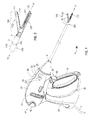
Fig. 1 is a front, perspective view of an endoscopic surgical forceps configured for use in accordance with the present disclosure; -
Fig. 2 is an enlarged, perspective view of an end effector assembly of the forceps ofFig. 1 ; -
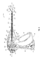
Fig. 3 is a longitudinal, cross-sectional view of the forceps ofFig. 1 ; -
Fig. 4A is a longitudinal, cross-sectional view of the end effector assembly ofFig. 2 with jaw members of the end effector assembly disposed in a spaced-apart position; -
Fig. 4B is a longitudinal, cross-sectional view of the end effector assembly ofFig. 2 with the jaw members disposed in an approximated position; -
Fig. 4C is a longitudinal, cross-sectional view of the end effector assembly ofFig. 2 with the jaw members disposed in the approximated position and a knife assembly disposed in a deployed position; -
Fig. 4D is a longitudinal, cross-sectional view of the end effector assembly ofFig. 2 with a monopolar assembly disposed in an extended position; -
Fig. 5 is a longitudinal, cross-sectional view of a distal end of the monopolar assembly ofFig. 4D ; -
Figs. 5A-5D are longitudinal, cross-sectional views of various distal tips releasably engageable with the monopolar assembly ofFig. 4D ; -
Fig. 6A is a side, perspective view of another end effector assembly configured for use with the forceps ofFig. 1 including a monopolar assembly disposed in a retracted position; -
Fig. 6B is a side, perspective view of the end effector assembly ofFig. 6A with the monopolar assembly disposed in an extended position; -
Fig. 6C is side, perspective view of another end effector assembly configured for use with the forceps ofFig. 1 including a monopolar assembly disposed in an extended position; -
Fig. 6D is side, perspective view of another end effector assembly configured for use with the forceps ofFig. 1 and shown with parts separated, the end effector assembly including a monopolar assembly disposed in a retracted position; -
Fig. 6E is a top, perspective view of another end effector assembly configured for use with the forceps ofFig. 1 shown including a monopolar assembly disposed in an extended position; -
Fig. 6F is a bottom, perspective view of the end effector assembly ofFig. 6E shown including the monopolar assembly disposed in a retracted position; -
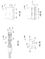
Fig. 7A is a top view of a jaw member of another end effector assembly configured for use with the forceps ofFig. 1 with a monopolar assembly disposed in an extended position; -
Fig. 7B is an end view of the jaw member ofFig. 7A with the monopolar assembly disposed in a retracted position; -
Fig. 8A is a longitudinal, cross-sectional view of another end effector assembly configured for use with the forceps ofFig. 1 with a monopolar assembly disposed in a retracted position; -
Fig. 8B is a longitudinal, cross-sectional view of the end effector assembly ofFig. 8A with the monopolar assembly disposed in an extended position; -
Fig. 9A is a side view of another end effector assembly configured for use with the forceps ofFig. 1 with jaw members disposed in a spaced-apart position; -
Fig. 9B is a side view of the end effector assembly ofFig. 9A with the jaw members disposed in an approximated position; -
Fig. 9C is a side view of the end effector assembly ofFig. 9A with the jaw members disposed in the approximated position and including an insulative sleeve disposed thereabout; and -
Fig. 10 is a side view of another end effector assembly configured for use with the forceps ofFig. 1 . - Referring now to
Figs. 1-3 , a forceps including features for operating in both a bipolar mode, e.g., for grasping, treating, and/or dissecting tissue, and a monopolar mode, e.g., for treating and/or dissecting tissue, is shown generally identified byreference numeral 10. Although shown as anendoscopic forceps 10, it is contemplated thatforceps 10 also be configured for use in connection with traditional open surgical procedures. Obviously, different electrical and mechanical connections and considerations apply to each particular configuration; however, the novel aspects with respect toforceps 10 and its operating characteristics remain generally consistent with respect to both the open and endoscopic configurations. - Continuing with reference to
Figs. 1-3 ,forceps 10 defines a longitudinal axis "X-X" and includes ahousing 20, ahandle assembly 30, aslide assembly 60, a rotatingassembly 70, atrigger assembly 80, anend effector assembly 100, and amonopolar assembly 200.Forceps 10 further includes ashaft 12 having adistal end 14 configured to mechanically engageend effector assembly 100 and aproximal end 16 that mechanically engageshousing 20.Forceps 10 also includeselectrosurgical cable 2 that connectsforceps 10 to a generator (not shown) or other suitable power source, althoughforceps 10 may alternatively be configured as a battery powered instrument.Cable 2 includeswires 2a extending therethrough that have sufficient length to extend throughshaft 12 in order to provide electrical energy to at least one of thetissue sealing plates jaw members end effector assembly 100, e.g., upon activation offirst activation switch 90.Wires 2b ofcable 2, on the other hand, extend throughhousing 20 in order to provide electrical energy tomonopolar assembly 200, e.g., upon activation ofsecond activation switch 95, as will be described in greater detail hereinbelow. - With continued reference to
Figs. 1-3 , handleassembly 30 includes fixedhandle 50 and amovable handle 40. Fixedhandle 50 is integrally associated withhousing 20 andmovable handle 40 is moveable relative to fixedhandle 50. Rotatingassembly 70 is rotatable in either direction about longitudinal axis "X-X" to rotateend effector 100 about longitudinal axis "X-X."Housing 20 houses the internal working components offorceps 10. - Referring still to
Figs. 1-3 ,end effector assembly 100 is shown attached at adistal end 14 ofshaft 12 and includes a pair of opposingjaw members jaw members outer jaw housing conductive plate respective jaw housings jaw members Tissue sealing plates jaw members wires 2a, for conducting energy therebetween and through tissue grasped betweenjaw members end effector assembly 100 defines a bipolar configuration whereintissue sealing plate 112 is charged to a first electrical potential andtissue sealing plate 122 is charged to a second, different electrical potential such that an electrical potential gradient is created for conducting energy betweentissue sealing plates First activation switch 90 is coupled towires 2a, thus allowing the user to selectively apply energy to sealingplates end effector assembly 100. -
End effector assembly 100 is designed as a unilateral assembly, i.e., wherejaw member 120 is fixed relative toshaft 12 andjaw member 110 is movable relative toshaft 12 and fixedjaw member 120. However,end effector assembly 100 may alternatively be configured as a bilateral assembly, i.e., where bothjaw member 110 andjaw member 120 are movable relative to one another and toshaft 12. In some embodiments, aknife assembly 180 is disposed withinshaft 12 and aknife channel jaw members knife 184 therethrough, e.g., via actuation of atrigger 82 oftrigger assembly 80. - Continuing with reference to
Figs. 1-3 ,movable handle 40 ofhandle assembly 30 is ultimately connected to adrive assembly 150 that, together, mechanically cooperate to impart movement ofjaw members Fig. 4A ) and an approximated position (Fig. 4B ) to grasp tissue betweentissue sealing plates jaw members drive assembly 150 includes a drive sleeve 155 (Fig. 3 ) that is operably coupled to jaw member 110 (and/or jaw member 120) such that longitudinally translation ofdrive sleeve 155 throughshaft 12 and relative to endeffector assembly 100 pivotsjaw member 110 relative tojaw member 120 between the spaced-apart and approximated positions for grasping tissue therebetween. As shown inFig. 1 ,movable handle 40 is initially spaced-apart from fixedhandle 50 and, correspondingly,jaw members Movable handle 40 is movable from this initial position to a depressed position for translatingdrive sleeve 155 proximally throughshaft 12 and relative to endeffector assembly 100 to movejaw members Fig. 4B ). Upon release (or return) ofmovable handle 40,drive sleeve 155 is translated distally under the bias of biasingmember 158 to returnjaw members - Referring now to
Figs. 1-4D ,monopolar assembly 200 offorceps 10 is shown generally inluding an electrically-insulative outertubular member 210 and an electrically-conductive innertubular member 220 that functions as the active electrode ofmonopolar assembly 200. Outertubular member 210 is disposed about and fixedly engaged to innertubular member 220 such that outertubular member 210 and innertubular member 220 move in concert with one another, although outer and innertubular members tubular member 210, may be positioned within electrically-conductive innertubular member 220 such that electrically-conductive innertubular member 220 is sandwiched between a pair of insulating tubular members, although other configurations are also contemplated. -
Monopolar assembly 200 is disposed aboutshaft 12 with proximal ends 211, 221 of outer and innertubular members housing 20.Proximal end 211 of outer tubular member 210 (and/orproximal end 221 of inner tubular member 220), which extends intohousing 20, is coupled withinhousing 20 to aslide assembly 60.Slide assembly 60 includes aslide knob 64 that extends from aslot 22 defined withinhousing 20 and is selectively translatable alongslot 22 to translatemonopolar assembly 200 relative toshaft 12 andend effector assembly 100 between a retracted position (Figs. 4A-4C ) and an extended position (Fig. 4D ), as will be described in greater detail below. Alternatively,shaft 12 may be coupled to slideassembly 60 andmonopolar assembly 200 may be fixedly engaged tohousing 20 such that, upon translation ofslide knob 64 ofslide assembly 60 alongslot 22,shaft 12 andend effector assembly 100 are translated relative tomonopolar assembly 200 between the retracted position (Figs. 4A-4C ) and the extended position (Fig. 4D ).Wires 2b ofcable 2 are coupled toproximal end 221 of innertubular member 220 to provide energy to innertubular member 220.Second activation switch 95, disposed onhousing 20, is coupled towires 2b to allow the user to selectively control the application of energy to innertubular member 220. - Inner
tubular member 220 includes abody portion 222 and adistal tip 224. At least a portion of adistal tip 224 of innertubular member 220 extends distally beyonddistal end 213 of outertubular member 210 ofmonopolar assembly 200 such that electrically-conductivedistal tip 224 is at least partially exposed. Thus, in the extended position (Fig. 4D ), as will be described in greater detail below, the exposed portion of electrically-conductivedistal tip 224 of innertubular member 220 extends distally beyondend effector assembly 100 to facilitate treating, e.g., mechanically, electrically, or electromechanically dissecting, tissue. For treating tissue withmonopolar assembly 200, energy is applied fromwires 2b, e.g., upon activation ofsecond activation switch 95, and is conducted along innertubular member 220 todistal tip 224 thereof for application to tissue. A return pad (not shown) is remotely placed to receive energy conducted from the monopolar electrode, e.g., innertubular member 220 and, more specifically,distal tip 224 thereof, through tissue.Distal tip 224, as will be described in greater detail below, may be releasably engageable withbody 222 of innertubular member 220 such thatmonopolar assembly 200 may assume various different configurations, depending on a particular purpose. -
Monopolar assembly 200 may be biased towards the retracted position and/or may include a locking assembly (not shown) for selectively lockingmonopolar assembly 200 in the retracted and/or the extended position. Further, internal circuitry (not explicitly shown) coupled to first and second activation switches 90, 95, respectively, andwires tissue sealing plates monopolar assembly 200 is disposed in the extended position and/or for inhibiting energization ofdistal tip 224 of innertubular member 220 whenmonopolar assembly 200 is disposed in the retracted position. Alternatively or additionally, mechanical mechanisms (not explicitly shown) for inhibiting activation of activation switches 90, 95 may also be provided for similar purposes. For example, the proximal end ofmonopolar assembly 200 may be configured to interfere withactivation switch 95 when in the retracted position, thereby inhibiting activation ofactivation switch 95 whenmonopolar assembly 200 is disposed in the retracted position. Such features may similarly apply to any of the other embodiments described herein. - Turning now to
Figs. 4A-4D , in conjunction withFig. 1 , the use and operation offorceps 10 in both the bipolar mode, e.g., for grasping, treating and/or cutting tissue, and the monopolar mode, e.g., for electrical/electromechanical tissue treatment, is described. Initially, with respect to the bipolar mode, as shown inFig. 4A ,jaw members monopolar assembly 200 remains disposed in the retracted position, as shown inFigs. 4A-4C , whereindistal tip 224 of innertubular member 220 is positioned proximally ofjaw members jaw members end effector assembly 100 may be maneuvered into position such that tissue to be grasped, treated, e.g., sealed, and/or cut, is disposed betweenjaw members movable handle 40 is depressed, or pulled proximally relative to fixedhandle 50 such thatjaw member 110 is pivoted relative tojaw member 120 from the spaced-apart position to the approximated position to grasp tissue therebetween, as shown inFig. 4B . More specifically, upon actuation ofmovable handle 40, drive sleeve 155 (Fig. 3 ) is translated proximally throughshaft 12, pullingjaw member 110 to pivot relative tojaw member 120 from the spaced-apart position to the approximated position. In this approximated position, energy may be supplied, e.g., via activation ofswitch 90, to tissue-sealingplate 112 ofjaw member 110 and/or tissue-sealingplate 122 ofjaw member 120 and conducted through tissue to treat tissue, e.g., to effect a tissue seal or otherwise treat tissue. - The disposition of
monopolar assembly 200 in the retracted position, e.g., wheredistal tip 224 of innertubular member 220 is proximally-spaced fromend effector assembly 100, as well as the positioning of insulative outertubular member 210 about innertubular member 220, helps inhibit capacitive coupling betweentissue sealing plates distal tip 224 ofmonopolar assembly 200, e.g., helps inhibitdistal tip 224 from being heated or energized, as energy is supplied totissue sealing plate 112 and/ortissue sealing plate 122 for tissue sealing (or otherwise treating tissue). Maintainingdistal tip 224 in an un-energized state while not in use helps protecttissue surrounding forceps 10. - As shown in
Fig. 4C , in conjunction withFig. 1 , once tissue treatment is complete (or to cut untreated tissue),knife 184 ofknife assembly 180 may be deployed from withinshaft 12 to betweenjaw members trigger 82 oftrigger assembly 80, to cut tissue grasped therebetween. More specifically, upon actuation oftrigger 82,knife 184 is advanced distally fromshaft 12 to extend at least partially throughknife channels jaw members jaw members knife 184 may be returned to withinshaft 12 andjaw members Fig. 4A ) to release the treated and/or divided tissue. - With reference to
Figs. 4B and 4D , in conjunction withFig. 1 , with respect to the monopolar mode,movable handle 40 is first depressed relative to fixedhandle 50 to pivotjaw member 110 relative tojaw member 120 from the spaced-apart position to the approximated position. Withjaw members monopolar assembly 200 may be translated from the retracted position (Fig. 4B ) to the extended position (Fig. 4D ). More specifically, in order to translatemonopolar assembly 200 from the retracted position (Fig. 4B ) to the extended position (Fig. 4D ),slide knob 64 ofslide assembly 60 is translated distally alongslot 22 defined withinhousing 20 fromproximal end 23 ofslot 22 todistal end 25 thereof such that outer and innertubular members shaft 12 and, ultimately, overjaw members distal tip 224 of innertubular member 220 extends distally fromend effector assembly 100. In the extended position, outertubular member 210 ofmonopolar assembly 200 is completely disposed overjaw members jaw members tubular members multiple slide knobs 64 may be provided for moving each of outer and innertubular members - With
monopolar assembly 200 disposed in the extended position, as shown inFig. 4D ,second activation switch 95 may be actuated to supply energy to innertubular member 220 such that energy is conducted along innertubular member 220 todistal tip 224 thereof, and fromdistal tip 224 to tissue to treat, e.g., dissect, tissue. As mentioned above, energy is returned via a remotely positioned return pad (not explicitly shown). During application of energy todistal tip 224,forceps 10 may be moved relative to tissue, e.g., longittadinally along longitudinal axis "X-X" and/or radially therefrom, to facilitate electromechanical treatment of tissue. Alternatively or additionally,forceps 10 may be moved relative to tissue to facilitate mechanically dissecting tissue, e.g., scoring tissue planes, withdistal tip 224 in the absence of energy being applied todistal tip 224. - During application of energy to
distal tip 224, outertubular member 210 electrically insulatesbody portion 222 of innertubular member 220 from surrounding tissue to help protect the surrounding tissue. Further, withjaw members insulative jaw housings tissue sealing plates tubular member 220 to help inhibit capacitive coupling therebetween. As mentioned above, a second electrically-insulative member (not explicitly shown) may be positioned within electrically-conductive innertubular member 220 to facilitate the isolation oftissue sealing plates distal tip 224 whenmonopolar assembly 220 is disposed in the retracted position. In either configuration, damage to surrounding tissue as a result of capacitive coupling is inhibited. - At the completion of tissue treatment, e.g., dissection,
monopolar assembly 200 may be returned to the retracted position (Figs. 4A-4B ), e.g., via translatingslide knob 64 ofslide assembly 60 proximally alongslot 22 toproximal end 23 thereof. Withmonopolar assembly 200 once again in the retracted position,jaw members end effector assembly 100 may be manipulated to grasp, treat, and/or cut tissue, as described above, in the bipolar mode. - Turning now to
Figs. 5 and 5A-5D ,monopolar assembly 200 is shown including a plurality ofdistal tips distal tips body 222 of innertubular member 220 ofmonopolar assembly 200. More specifically,body 222 of innertubular member 220 includes an engagement feature, e.g., threading 226, defined atdistal end 223 thereof, whiledistal tips complimentary threading 228, at the proximal end thereof for releasable engagement with threading 226 ofbody 222 of innertubular member 220. Other releasably engagement features are also contemplated, e.g., friction-fitting, latching, etc. - With continued reference to
Figs. 5 and 5A-5D , various different configurations ofdistal tips Distal tip 224a is shown inluding a beveleddistal end 225a;distal tip 224b is shown including a generallylinear blade 225b extending distally therefrom;distal tip 224c is shown including a hook 225c extending distally therefrom; anddistal tip 224d is shown defining a generally annulardistal end 225d. Other configurations may also be provided. A desired configuration of distal tip may be selected and engaged tobody 222 of innertubular member 220 depending on the particular purpose. For example, where it is desired to treat tissue via distal advancement of forceps 10 (Fig. 1 ),distal tip 224a,distal tip 224b, ordistal tip 224d may be selected (depending on the size and/or composition of tissue to be dissected). On the other hand, where it is desired to treat tissue via proximal movement of forceps 10 (Fig. 1 ),distal tip 224c may be selected. - Various other embodiments of end effector assemblies and/or monopolar assemblies provided in accordance with the present disclosure and configured for use with forceps 10 (
Fig. 1 ) or any other suitable surgical instrument are described below with reference toFigs. 6A-10 . These end effector assemblies and/or monopolar assemblies are similar to endeffector assembly 100 and monopolar assembly 200 (seeFigs. 1-3 ), respectively, described above. Accordingly, for purposes of brevity, only the differences will be described hereinbelow, keeping in mind that any or all of the features of end effector assembly 100 (Fig. 2 ), monopolar assembly 200 (Fig. 3 ), and/or forceps 10 (Fig. 1 ), to the extent consistent, may similarly apply to the end effector assemblies, monopolar assemblies, and instruments associated therewith, respectively, described below. - Turning now to
Figs. 6A-6B , another embodiment of a monopolar assembly provided in accordance with the present disclosure is shown generally identified byreference numeral 300.Monopolar assembly 300 is configured for use withend effector assembly 100 and a forceps similar to forceps 10 (Fig. 1 ), except that shaft 12' of the forceps further includes an insulative member, e.g., distal sleeve 18', mounted thereon towards distal end 14' thereof that is configured to receive electrically-conductivemonopolar rod member 320 therein whenmonopolar assembly 300 is disposed in the retracted position, as will be described below. Further,monopolar assembly 300 is similar to monopolar assembly 200 (Fig. 3 ), except that, rather than including an electrically-conductive inner tubular member 220 (Fig. 3 ),monopolar assembly 300 includes amonopolar rod member 320 having an exposed electrically-conductive portion, e.g.,distal tip 324. - With continued reference to
Figs. 6A-6B ,monopolar assembly 300 includes an electrically-insulative outertubular member 310 that is disposed about shaft 12' and amonopolar rod member 320 that extends through outer tubular member 310 (adjacent shaft 12') and distally therefrom, ultimately defining an exposed electrically-conductive hook-shaped distal tip 324 (although other configurations may also be provided).Rod member 320 and, more specifically,distal tip 324 thereof, functions as the active electrode ofmonopolar assembly 300. Outertubular member 310 may be fixedly engaged torod member 320 such that outertubular member 310 androd member 320 move in concert with one another between the retracted position (FIG. 6A ) and the extended position (Fig. 6B ), e.g., upon translation of slide knob 64 (Fig. 1 ). Alternatively, outertubular member 310 androd member 320 may be coupled to one another to effect simultaneous but differential deployment of outertubular member 310 androd member 320 relative to one another, or may be independent of one another such that outertubular member 310 and/orrod member 320 may be selectively deployed independently of one another. - In the retracted position, as shown in
Fig. 6A ,distal tip 324 ofmonopolar assembly 300 is disposed within an insulating member, e.g., distal sleeve 18' of shaft 12', disposed towards distal end 14' of shaft 12'. Distal sleeve 18' is electrically-insulated such thatdistal tip 324 ofrod member 320 is isolated fromtissue sealing plates jaw members - In the extended position, as shown in
Fig. 6B , outertubular member 310 is disposed aboutjaw members end effector assembly 100, whiledistal tip 324 ofrod member 320 extends distally therefrom. In this position, energy may be applied todistal tip 324 ofrod member 320 to treat tissue. A return pad (not shown) positioned at a remote location is used to return energy transmitted fromdistal tip 324 ofrod member 320 through tissue. Further, in the extended position,monopolar assembly 300 and, more particularly,rod member 320 thereof, may be rotated relative to endeffector assembly 100, e.g., via rotating a second rotating assembly (similar to rotating assembly 70 (Fig. 1 )) disposed within housing 20 (Fig. 1 ) and coupled tomonopolar assembly 300, to better positiondistal tip 324 ofrod member 320 relative to tissue. - Turning to
Fig. 6C , another embodiment of amonopolar assembly 400 similar tomonopolar assembly 300 is shown.Monopolar assembly 400 differs frommonopolar assembly 300 in that insulative outertubular member 410 ofmonopolar assembly 400 forms the shaft of the forceps (or is fixedly disposed about the shaft of the forceps) and is fixed in position relative to endeffector assembly 100.Monopolar rod member 420 extends through and distally from outertubular member 410 and is movable relative to endeffector assembly 100 and insulative outertubular member 410 between the retracted position and the extended position.Rod member 420 may include an insulative sleeve orcoating 426 disposed aboutbody portion 422 thereof, such thatdistal hook 424 is the only exposed electrically-conductive portion ofrod member 420.Distal hook 424 ofrod member 420 is received within a recess defined within adistal sleeve 418 that extends fromdistal end 414 of outertubular member 410 when in the retracted position, thereby helping to protect surrounding tissue. - Referring to
Fig. 6D , another embodiment of an end effector assembly 100' incorporating a monopolar assembly 400' is shown. End effector assembly 100' is similar to end effector assembly 100 (Figs. 1-4D ), while monopolar assembly 400' is similar to monopolar assembly 300 (Fig. 6A-6B ) and monopolar assembly 400 (Fig. 6C ). Accordingly, only the differences between end effector assembly 100' and monopolar assembly 400' as compared to the previous embodiments described hereinabove will be described in detail below. - Continuing with reference to
Fig. 6D , each jaw member 110', 120' of end effector assembly 100' includes a distal jaw portion 111', 121' including a tissue sealing surface defined by an electrically-conductive tissue-sealing plate 112', 122', and a proximal flange 114', 124' extending proximally from the respective distal jaw portion 111', 121'. Proximal flanges 114', 124' are configured to receive pivot pin 95' to pivotably couple jaw members 110', 120' to one another and may be formed at least partially from, or coated at least partially with an insulative material. The proximal flange of one of the jaw members, e.g., proximal flange 124' of jaw member 120', further defines a lumen 126' extending therethrough and a recess 128' defined within the distal surface of proximal flange 124' that communicates with lumen 126'. This configuration of proximal flange 124' of jaw member 120' permits body 422' of rod member 420' of monopolar assembly 400' to extend through proximal flange 124' of jaw member 120', e.g., through lumen 126', while also permitting distal hook 424' of rod member 420' of monopolar assembly 400' to be received within recess 128' of proximal flange 124' when monopolar assembly 400' is disposed in the retracted position, thereby helping to protect surrounding tissue, In other words, rather than providing an insulative sleeve for retaining monopolar assembly 400' when monopolar assembly 400' is disposed in the retracted position, jaw member 120' itself is configured to retain monopolar assembly 400' therein when monopolar assembly 400' is disposed in the retracted position. - Turning now to
Figs. 6E-6F , another embodiment of anend effector assembly 100" incorporating amonopolar assembly 400" is shown.End effector assembly 100" is similar to end effector assembly 100' (Fig. 6D ), whilemonopolar assembly 400" is similar to monopolar assembly 400' (Fig. 6D ), althoughend effector assembly 100" and/ormonopolar assembly 400" may alternatively be configured similarly to any of the other end effector assemblies and monopolar assemblies described herein. For purposes of brevity, only the differences betweenend effector assembly 100" andmonopolar assembly 400" as compared to end effector assembly 100' (Fig. 6D ) and monopolar assembly 400' (Fig. 6D ), respectively, will be described in detail below. - With continued reference to
Figs. 6E-6F , eachjaw member 110", 120" ofend effector assembly 100" includes adistal jaw portion 111", 121" having a tissue-sealingplate 112", 122" disposed thereon, and aproximal flange 114", 124" extending proximally from the respectivedistal jaw portion 111", 121". The proximal flange of one of the jaw members, e.g.,proximal flange 124" ofjaw member 120", further defines alumen 126" and arecess 128" configured to receivebody 422" ofrod member 420" ofmonopolar assembly 400" anddistal hook 424" ofrod member 420" ofmonopolar assembly 400", respectively, whenmonopolar assembly 400" is disposed in the retracted position (Fig. 6F ). Further,jaw members 110" and 120" ofend effector assembly 100" define curved configurations, e.g., to facilitate manipulation of tissue and to provide better "line of sight" for accessing targeted tissues, although other configurations may also be provided. More specifically,jaw members 110", 120" are curved towards the side ofend effector assembly 100" whereinmonopolar assembly 400" is disposed, such that the overall width dimension ofend effector assembly 100" is not increased by the presence ofmonopolar assembly 400". - One of the jaw members, e.g.,
jaw member 120", includes a channel-shaped cut-out 129" defined withindistal jaw portion 121" towards the distal end thereof. Cut-out 129" is configured to permit reciprocation ofmonopolar assembly 400" between the retracted position, whereinmonopolar assembly 400" is disposed withinproximal flange 124" ofjaw member 120", and the extended position, whereindistal hook 424" ofmonopolar assembly 400" extends distally fromend effector assembly 100". More specifically, due to the curved configurations ofjaw members 110", 120", the distal end ofjaw member 120" curves into the path ofmonopolar assembly 400". Cut-out 129" defines a channel through whichmonopolar assembly 400" is configured to extend, thus permitting extension ofdistal hook 424" distally beyondend effector assembly 100" without interference byjaw member 120" and guiding the extension/retraction ofmonopolar assembly 400". - With reference to
Figs. 7A-7B , ajaw member 520 of anend effector assembly 500 that incorporates amonopolar rod member 530 therein is shown.Jaw member 520, similar tojaw members Figs. 1-3 ), incudes an insulativeouter jaw housing 521 and an electrically-conductivetissue sealing plate 522 disposed atopjaw housing 521. However,jaw housing 521 further includes a lumen (not explicitly shown) extending therethrough that is configured to slidably receivebody 532 ofrod member 530 and a complementary-shapedrecess 528 defined therein that communicates with the lumen (not explicitly shown).Recess 528 is defined withindistal end 523 ofjaw member 520 and is configured to receivedistal tip 534 ofrod member 530 therein whenrod member 530 is disposed in the retracted position. More specifically, in the retracted position,rod member 530 is fully disposed withinrecess 528 ofjaw housing 521 ofjaw member 520 such thatrod member 530 is electrically insulated from tissue sealing plate 522 (and the tissue sealing plate of the other jaw member (not shown) of end effector assembly 500). In the extended position,rod member 530 extends distally fromrecess 528 andjaw member 520 to facilitate monopolar tissue treatment. As in the previous embodiments, an insulative tubular member (not explicitly shown) may be provided to slide distally over and further electrically insulateend effector assembly 500 fromrod member 530 asrod member 530 is moved to the extended position.Rod member 530 may also be rotatable relative to endeffector assembly 500. - Referring to
Figs. 8A-8B , another embodiment of anend effector assembly 600 similar to end effector assembly 500 (Figs. 7A-7B ) is shown including amonopolar wire member 630 within one of thejaw members jaw member 620. More specifically,jaw member 620 includes alumen 626 extending longitudinally throughinsulative jaw housing 621 thereof and an electrically-conductivemonopolar wire member 630 slidably received withinlumen 626. At least a portion ofwire member 630 is formed from a resilient material, or is otherwise configured such thatdistal tip 634 ofwire member 630 is capable of assuming a substantially linear configuration relative tobody 632 ofwire member 630, thus permittingwire member 630 to be completely retracted withinlumen 626 in a substantially linear configuration. Upon extension ofwire member 630 fromlumen 626, e.g., upon movement ofwire member 630 to the extended position,distal tip 634 ofwire member 630 assumes a curved, hook-shaped, or other suitable configuration to facilitate tissue dissection.Wire member 630 may also be rotatable relative tojaw member 620 when in the extended position, similarly as described above with respect to rod member 330 (Figs. 6A-6B ). Further, an outer insulative sleeve (not shown) may also be provided to surroundend effector assembly 600 upon extension ofmonopolar member 630, similarly as described above with respect to the previous embodiments. - Turning now to
Figs. 9A-9B , another embodiment of an end effector assembly provided in accordance with the present disclosure is shown generally indentified byreference numeral 700.End effector assembly 700 includes first and second electrically-conductive jaw members 710, 720 (although a portion ofjaw members jaw member linear body portion tissue sealing surface jaw members distal portion respective body portion Jaw members jaw member 710 is charged to a first electrical potential andjaw member 720 is charged to a second, different electrical potential such that an electrical potential gradient is created for conducting energy therebetween and through tissue grasped therebetween for treating e.g., sealing, tissue. - In the monopolar mode, on the other hand,
jaw members jaw members distal portions jaw members jaw members distal portions jaw members distal portion 714 and/or hooked distal portion 724 (either alone or in cooperation with one another) define a monopolar,active electrode probe 730. That is, rather than providing a separate monopolar element,distal portions jaw members - Turning to
Fig. 9C ,end effector assembly 700, in some embodiments, may further include an insulativetubular member 740 disposed aboutbody portions jaw members tubular member 740 includes a distal cut-out 742 such thatmonopolar probe 730, e.g., hookeddistal portions jaw member tubular member 740 is extended aboutend effector 700 to facilitate monopolar tissue treatment. This configuration also protects surrounding tissue by electrically isolatingbody portions jaw members tubular member 740 may be extended and retracted similarly as described above with respect to any of the previous embodiments. - With reference to
Fig. 10 , another embodiment of an end effector assembly provided in accordance with the present disclosure and configured for operation in both a bipolar mode and a monopolar mode is shown generally indentified byreference numeral 800.End effector assembly 800 is similar to end effector assembly 700 (Figs. 9A-9C ), except that, rather than including generally linear body portions and hook-shaped distal portions,jaw members jaw members Figs. 9A-9C ), a monopolar,active electrode probe 830 is formed via the cooperation of distal ends 814, 824 ofjaw members jaw members Figs. 9A-9C ), described above and to the extent consistent, apply similarly to endeffector assembly 800 and, thus, are not repeated here. - From the foregoing and with reference to the various figure drawings, those skilled in the art will appreciate that certain modifications can also be made to the present disclosure without departing from the scope of the same. While several embodiments of the disclosure have been shown in the drawings, it is not intended that the disclosure be limited thereto, as it is intended that the disclosure be as broad in scope as the art will allow and that the specification be read likewise. Therefore, the above description should not be construed as limiting, but merely as exemplifications of particular embodiments. Those skilled in the art will envision other modifications within the scope and spirit of the claims appended hereto.
Claims (17)
- A forceps, comprising:an end effector assembly including first and second jaw members configured to grasp tissue therebetween and conduct energy through tissue grasped therebetween to treat tissue;an insulative tubular member movable relative to the end effector assembly between a retracted position, wherein the insulative tubular member is positioned proximally of the end effector assembly, and an extended position, wherein the insulative tabular member is disposed about the end effector assembly; anda monopolar member selectively deployable relative to the end effector assembly from a first position to a second position, wherein, in the second position, a portion of the monopolar member extends distally from the end effector assembly and the insulative tubular member for applying energy to tissue to treat tissue.
- The forceps according to claim 1, wherein the monopolar member incudes an elongated rod member having an electrically-conductive distal tip, the electrically-conductive distal tip configured to extend distally from the end effector assembly and the insulative tubular member when disposed in the second position.
- The forceps according to claim 2, wherein, in the first position, the distal tip is disposed within a longitudinal lumen extending through a distal jaw housing of one of the jaw members.
- The forceps according to claim 2, wherein, in the first position, the distal tip is disposed within a recess defined within a distal jaw housing of one of the jaw members.
- The forceps according to claim 2, wherein, in the first position, the distal tip is disposed within a recess defined within a proximal flange portion of one of the jaw members.
- The forceps according to claim 2, wherein, in the first position, the distal tip is disposed within an insulative sleeve positioned proximally of the end effector assembly.
- The forceps according to any one of claims 2 to 8, wherein one of the jaw members defines a cut-out configured to receive a portion of the monopolar member when the monopolar member is disposed in the second position.
- The forceps according to claim 2, wherein the electrically-conductive distal tip defines a hook-shaped configuration.
- The forceps according to any preceding claim, wherein the insulative tubular member and the monopolar member are coupled to one another such that, as the insulative tubular member is moved between the retracted position and the extended position, the monopolar member is moved between the first position and the second position.
- The forceps according to any one of claims 1 to 8, wherein the insulative tubular member and the monopolar member are independently movable relative to one another.
- A forceps, comprising:an end effector assembly including first and second jaw members configured to grasp tissue therebetween and conduct energy through tissue grasped therebetween to treat tissue;an insulative tubular member movable relative to the end effector assembly between a retracted position, wherein the insulative tubular member is positioned proximally of the end effector assembly, and an extended position, wherein the insulative tubular member is disposed about the end effector assembly; andan elongated rod member having an electrically-conductive distal tip, the rod member selectively deployable relative to the end effector assembly from a first position, wherein the distal tip is disposed proximally of the end effector assembly, to a second position, wherein the distal tip extends distally from the end effector assembly and the insulative tubular member for applying energy to tissue to treat tissue.
- The forceps according to claim 2 or 11, wherein, in the second position, the elongated rod member extends alongside the end effector assembly and the distal tip extends distally from the end effector assembly.
- The forceps according to claim 12, wherein the jaw members define a curved configuration, the jaw members curving towards the elongated rod member such that a portion of one of the jaw members extends into a travel path of the elongated rod member, the one of the jaw members defining a cut-out configured to receive the elongated rod member to permit movement of the elongated rod member between the first and second positions.
- The forceps according to claim 11, wherein each jaw member includes a distal jaw portion and a proximal flange, the proximal flange of one of the jaw members defining a recess configured to receive the distal tip when the elongated rod member is disposed in the first position.
- The forceps according to claim 11, wherein, in the first position, the distal tip is disposed within an insulative sleeve positioned proximally of the end effector assembly.
- The forceps according to any one of claims 11 to 15, wherein the insulative tubular member and the elongated rod member are coupled to one another such that, as the insulative tubular member is moved between the retracted position and the extended position, the elongated rod member is moved between the first position and the second position.
- The forceps according to any one of claims 11 to 15, wherein the insulative tubular member and the elongated rod member are independently movable relative to one another.
Applications Claiming Priority (1)
| Application Number | Priority Date | Filing Date | Title |
|---|---|---|---|
| US13/537,517 US9072524B2 (en) | 2012-06-29 | 2012-06-29 | Surgical forceps |
Publications (2)
| Publication Number | Publication Date |
|---|---|
| EP2679185A1 true EP2679185A1 (en) | 2014-01-01 |
| EP2679185B1 EP2679185B1 (en) | 2015-04-22 |
Family
ID=48746318
Family Applications (1)
| Application Number | Title | Priority Date | Filing Date |
|---|---|---|---|
| EP20130174296 Active EP2679185B1 (en) | 2012-06-29 | 2013-06-28 | Surgical forceps |
Country Status (7)
| Country | Link |
|---|---|
| US (1) | US9072524B2 (en) |
| EP (1) | EP2679185B1 (en) |
| JP (1) | JP5687309B2 (en) |
| CN (3) | CN103505281B (en) |
| AU (1) | AU2013205762B2 (en) |
| CA (1) | CA2816192C (en) |
| ES (1) | ES2535492T3 (en) |
Cited By (8)
| Publication number | Priority date | Publication date | Assignee | Title |
|---|---|---|---|---|
| EP2901952A1 (en) * | 2014-01-29 | 2015-08-05 | Covidien LP | Tissue sealing instrument with tissue-dissecting electrode |
| EP3020354A1 (en) * | 2014-11-17 | 2016-05-18 | Covidien LP | Deployment mechanism for surgical instruments |
| EP3020351A1 (en) * | 2014-11-17 | 2016-05-18 | Covidien LP | Deployment mechanisms for surgical instruments |
| EP3020353A1 (en) * | 2014-11-17 | 2016-05-18 | Covidien LP | Deployment mechanisms for multi-function surgical instruments |
| EP3020341A1 (en) * | 2014-11-17 | 2016-05-18 | Covidien LP | Deployment mechanisms for multi-function surgical instruments |
| EP3031420A1 (en) * | 2014-12-10 | 2016-06-15 | Covidien LP | Energizable attachment for surgical devices |
| WO2020201904A1 (en) * | 2019-04-04 | 2020-10-08 | Ethicon Llc | Monopolar and bipolar functionality |
| WO2026053054A1 (en) * | 2024-09-05 | 2026-03-12 | Covidien Lp | Activation assemblies for electrosurgical instruments |
Families Citing this family (112)
| Publication number | Priority date | Publication date | Assignee | Title |
|---|---|---|---|---|
| US7364577B2 (en) | 2002-02-11 | 2008-04-29 | Sherwood Services Ag | Vessel sealing system |
| US7628791B2 (en) | 2005-08-19 | 2009-12-08 | Covidien Ag | Single action tissue sealer |
| US8298232B2 (en) | 2006-01-24 | 2012-10-30 | Tyco Healthcare Group Lp | Endoscopic vessel sealer and divider for large tissue structures |
| US8357158B2 (en) | 2008-04-22 | 2013-01-22 | Covidien Lp | Jaw closure detection system |
| US8469956B2 (en) | 2008-07-21 | 2013-06-25 | Covidien Lp | Variable resistor jaw |
| US8663220B2 (en) | 2009-07-15 | 2014-03-04 | Ethicon Endo-Surgery, Inc. | Ultrasonic surgical instruments |
| US8133254B2 (en) | 2009-09-18 | 2012-03-13 | Tyco Healthcare Group Lp | In vivo attachable and detachable end effector assembly and laparoscopic surgical instrument and methods therefor |
| US11090104B2 (en) | 2009-10-09 | 2021-08-17 | Cilag Gmbh International | Surgical generator for ultrasonic and electrosurgical devices |
| US8480671B2 (en) | 2010-01-22 | 2013-07-09 | Covidien Lp | Compact jaw including split pivot pin |
| US8439913B2 (en) | 2010-04-29 | 2013-05-14 | Covidien Lp | Pressure sensing sealing plate |
| US8430877B2 (en) | 2010-06-02 | 2013-04-30 | Covidien Lp | Apparatus for performing an electrosurgical procedure |
| US8491624B2 (en) | 2010-06-02 | 2013-07-23 | Covidien Lp | Apparatus for performing an electrosurgical procedure |
| US8469991B2 (en) | 2010-06-02 | 2013-06-25 | Covidien Lp | Apparatus for performing an electrosurgical procedure |
| US9844384B2 (en) | 2011-07-11 | 2017-12-19 | Covidien Lp | Stand alone energy-based tissue clips |
| US8968309B2 (en) | 2011-11-10 | 2015-03-03 | Covidien Lp | Surgical forceps |
| US8747434B2 (en) | 2012-02-20 | 2014-06-10 | Covidien Lp | Knife deployment mechanisms for surgical forceps |
| US9439668B2 (en) | 2012-04-09 | 2016-09-13 | Ethicon Endo-Surgery, Llc | Switch arrangements for ultrasonic surgical instruments |
| US8968311B2 (en) | 2012-05-01 | 2015-03-03 | Covidien Lp | Surgical instrument with stamped double-flag jaws and actuation mechanism |
| US9668807B2 (en) | 2012-05-01 | 2017-06-06 | Covidien Lp | Simplified spring load mechanism for delivering shaft force of a surgical instrument |
| US9820765B2 (en) | 2012-05-01 | 2017-11-21 | Covidien Lp | Surgical instrument with stamped double-flange jaws |
| US9375258B2 (en) | 2012-05-08 | 2016-06-28 | Covidien Lp | Surgical forceps |
| US9039731B2 (en) | 2012-05-08 | 2015-05-26 | Covidien Lp | Surgical forceps including blade safety mechanism |
| US9393037B2 (en) | 2012-06-29 | 2016-07-19 | Ethicon Endo-Surgery, Llc | Surgical instruments with articulating shafts |
| US9408622B2 (en) | 2012-06-29 | 2016-08-09 | Ethicon Endo-Surgery, Llc | Surgical instruments with articulating shafts |
| US10368945B2 (en) | 2012-07-17 | 2019-08-06 | Covidien Lp | Surgical instrument for energy-based tissue treatment |
| US8939975B2 (en) | 2012-07-17 | 2015-01-27 | Covidien Lp | Gap control via overmold teeth and hard stops |
| US9301798B2 (en) | 2012-07-19 | 2016-04-05 | Covidien Lp | Surgical forceps including reposable end effector assemblies |
| US9636168B2 (en) | 2012-08-09 | 2017-05-02 | Covidien Lp | Electrosurgical instrument including nested knife assembly |
| US9433461B2 (en) | 2012-09-07 | 2016-09-06 | Covidien Lp | Instruments, systems, and methods for sealing tissue structures |
| US9687290B2 (en) | 2012-10-02 | 2017-06-27 | Covidien Lp | Energy-based medical devices |
| US9439711B2 (en) | 2012-10-02 | 2016-09-13 | Covidien Lp | Medical devices for thermally treating tissue |
| US9549749B2 (en) | 2012-10-08 | 2017-01-24 | Covidien Lp | Surgical forceps |
| US9526564B2 (en) | 2012-10-08 | 2016-12-27 | Covidien Lp | Electric stapler device |
| US9265566B2 (en) | 2012-10-16 | 2016-02-23 | Covidien Lp | Surgical instrument |
| US9095367B2 (en) | 2012-10-22 | 2015-08-04 | Ethicon Endo-Surgery, Inc. | Flexible harmonic waveguides/blades for surgical instruments |
| US9375259B2 (en) | 2012-10-24 | 2016-06-28 | Covidien Lp | Electrosurgical instrument including an adhesive applicator assembly |
| US10772674B2 (en) | 2012-11-15 | 2020-09-15 | Covidien Lp | Deployment mechanisms for surgical instruments |
| US9375205B2 (en) | 2012-11-15 | 2016-06-28 | Covidien Lp | Deployment mechanisms for surgical instruments |
| WO2014156219A1 (en) * | 2013-03-29 | 2014-10-02 | オリンパス株式会社 | High-frequency treatment tool |
| USD728786S1 (en) | 2013-05-03 | 2015-05-05 | Covidien Lp | Vessel sealer with mechanical cutter and pistol-grip-style trigger |
| US9642671B2 (en) | 2013-09-30 | 2017-05-09 | Covidien Lp | Limited-use medical device |
| USD788302S1 (en) | 2013-10-01 | 2017-05-30 | Covidien Lp | Knife for endoscopic electrosurgical forceps |
| US20150238260A1 (en) * | 2014-02-26 | 2015-08-27 | Covidien Lp | Surgical instruments including nerve stimulator apparatus for use in the detection of nerves in tissue and methods of directing energy to tissue using same |
| JP6099818B2 (en) * | 2014-09-05 | 2017-03-22 | オリンパス株式会社 | Grasping treatment unit, grasping treatment instrument, and grasping treatment system |
| US10039593B2 (en) | 2014-09-17 | 2018-08-07 | Covidien Lp | Surgical instrument having a bipolar end effector assembly and a deployable monopolar assembly |
| US10080605B2 (en) | 2014-09-17 | 2018-09-25 | Covidien Lp | Deployment mechanisms for surgical instruments |
| US9987076B2 (en) | 2014-09-17 | 2018-06-05 | Covidien Lp | Multi-function surgical instruments |
| US10080606B2 (en) | 2014-09-17 | 2018-09-25 | Covidien Lp | Method of forming a member of an end effector |
| US9918785B2 (en) | 2014-09-17 | 2018-03-20 | Covidien Lp | Deployment mechanisms for surgical instruments |
| US10039592B2 (en) | 2014-09-17 | 2018-08-07 | Covidien Lp | Deployment mechanisms for surgical instruments |
| WO2016045041A1 (en) | 2014-09-25 | 2016-03-31 | Covidien Lp | Surgical instruments facilitating replacement of disposable components and/or sterilization of reusable components |
| US10172612B2 (en) | 2015-01-21 | 2019-01-08 | Covidien Lp | Surgical instruments with force applier and methods of use |
| US10398459B2 (en) | 2015-04-02 | 2019-09-03 | Aod Holdings Llc | Combination device for endoscopic and arthroscopic surgical procedures |
| US20160302791A1 (en) * | 2015-04-17 | 2016-10-20 | Covidien Lp | Powered surgical instrument with a deployable ablation catheter |
| WO2017010168A1 (en) * | 2015-07-16 | 2017-01-19 | オリンパス株式会社 | Treatment too |
| USD844138S1 (en) | 2015-07-17 | 2019-03-26 | Covidien Lp | Handle assembly of a multi-function surgical instrument |
| USD844139S1 (en) | 2015-07-17 | 2019-03-26 | Covidien Lp | Monopolar assembly of a multi-function surgical instrument |
| EP3337923B2 (en) | 2015-09-21 | 2023-01-04 | Modern Meadow, Inc. | Fiber reinforced tissue composites |
| US11076909B2 (en) | 2015-09-25 | 2021-08-03 | Gyrus Acmi, Inc. | Multifunctional medical device |
| US11020166B2 (en) | 2015-09-25 | 2021-06-01 | Gyrus Acmi, Inc. | Multifunctional medical device |
| US10687884B2 (en) | 2015-09-30 | 2020-06-23 | Ethicon Llc | Circuits for supplying isolated direct current (DC) voltage to surgical instruments |
| US10595930B2 (en) | 2015-10-16 | 2020-03-24 | Ethicon Llc | Electrode wiping surgical device |
| US10966717B2 (en) * | 2016-01-07 | 2021-04-06 | Covidien Lp | Surgical fastener apparatus |
| US11129670B2 (en) | 2016-01-15 | 2021-09-28 | Cilag Gmbh International | Modular battery powered handheld surgical instrument with selective application of energy based on button displacement, intensity, or local tissue characterization |
| US11058448B2 (en) | 2016-01-15 | 2021-07-13 | Cilag Gmbh International | Modular battery powered handheld surgical instrument with multistage generator circuits |
| US12193698B2 (en) | 2016-01-15 | 2025-01-14 | Cilag Gmbh International | Method for self-diagnosing operation of a control switch in a surgical instrument system |
| US11229471B2 (en) | 2016-01-15 | 2022-01-25 | Cilag Gmbh International | Modular battery powered handheld surgical instrument with selective application of energy based on tissue characterization |
| JP7109882B2 (en) | 2016-02-15 | 2022-08-01 | モダン メドウ,インコーポレイテッド | Method for making biofabricated materials containing collagen fibrils |
| US10537381B2 (en) * | 2016-02-26 | 2020-01-21 | Covidien Lp | Surgical instrument having a bipolar end effector assembly and a deployable monopolar assembly |
| US10456193B2 (en) | 2016-05-03 | 2019-10-29 | Ethicon Llc | Medical device with a bilateral jaw configuration for nerve stimulation |
| JP6626969B2 (en) * | 2016-06-20 | 2019-12-25 | オリンパス株式会社 | Treatment tool |
| US11266430B2 (en) | 2016-11-29 | 2022-03-08 | Cilag Gmbh International | End effector control and calibration |
| US11154348B2 (en) | 2017-08-29 | 2021-10-26 | Covidien Lp | Surgical instruments and methods of assembling surgical instruments |
| AU2018253595A1 (en) | 2017-11-13 | 2019-05-30 | Modern Meadow, Inc. | Biofabricated leather articles having zonal properties |
| US11241275B2 (en) | 2018-03-21 | 2022-02-08 | Covidien Lp | Energy-based surgical instrument having multiple operational configurations |
| US11123132B2 (en) | 2018-04-09 | 2021-09-21 | Covidien Lp | Multi-function surgical instruments and assemblies therefor |
| US10828756B2 (en) | 2018-04-24 | 2020-11-10 | Covidien Lp | Disassembly methods facilitating reprocessing of multi-function surgical instruments |
| WO2020018371A1 (en) * | 2018-07-17 | 2020-01-23 | Intuitive Surgical Operations, Inc. | Surgical instruments with reduced capacitance, related devices, and related methods |
| AU2020209847B2 (en) | 2019-01-17 | 2024-10-17 | Modern Meadow, Inc. | Layered collagen materials and methods of making the same |
| US11241269B2 (en) | 2019-04-04 | 2022-02-08 | Cilag Gmbh International | Surgical devices switchable between monopolar functionality and bipolar functionality |
| US11471212B2 (en) | 2019-04-04 | 2022-10-18 | Cilag Gmbh International | Electrosurgical devices with monopolar and bipolar functionality |
| US11707318B2 (en) | 2019-12-30 | 2023-07-25 | Cilag Gmbh International | Surgical instrument with jaw alignment features |
| US11723716B2 (en) * | 2019-12-30 | 2023-08-15 | Cilag Gmbh International | Electrosurgical instrument with variable control mechanisms |
| US11660089B2 (en) | 2019-12-30 | 2023-05-30 | Cilag Gmbh International | Surgical instrument comprising a sensing system |
| US11779387B2 (en) | 2019-12-30 | 2023-10-10 | Cilag Gmbh International | Clamp arm jaw to minimize tissue sticking and improve tissue control |
| US11986201B2 (en) | 2019-12-30 | 2024-05-21 | Cilag Gmbh International | Method for operating a surgical instrument |
| US12349961B2 (en) | 2019-12-30 | 2025-07-08 | Cilag Gmbh International | Electrosurgical instrument with electrodes operable in bipolar and monopolar modes |
| US11786291B2 (en) | 2019-12-30 | 2023-10-17 | Cilag Gmbh International | Deflectable support of RF energy electrode with respect to opposing ultrasonic blade |
| US11779329B2 (en) | 2019-12-30 | 2023-10-10 | Cilag Gmbh International | Surgical instrument comprising a flex circuit including a sensor system |
| US12262937B2 (en) | 2019-12-30 | 2025-04-01 | Cilag Gmbh International | User interface for surgical instrument with combination energy modality end-effector |
| US12082808B2 (en) | 2019-12-30 | 2024-09-10 | Cilag Gmbh International | Surgical instrument comprising a control system responsive to software configurations |
| US11944366B2 (en) | 2019-12-30 | 2024-04-02 | Cilag Gmbh International | Asymmetric segmented ultrasonic support pad for cooperative engagement with a movable RF electrode |
| US12053224B2 (en) | 2019-12-30 | 2024-08-06 | Cilag Gmbh International | Variation in electrode parameters and deflectable electrode to modify energy density and tissue interaction |
| US12114912B2 (en) | 2019-12-30 | 2024-10-15 | Cilag Gmbh International | Non-biased deflectable electrode to minimize contact between ultrasonic blade and electrode |
| US12076006B2 (en) | 2019-12-30 | 2024-09-03 | Cilag Gmbh International | Surgical instrument comprising an orientation detection system |
| US11937863B2 (en) | 2019-12-30 | 2024-03-26 | Cilag Gmbh International | Deflectable electrode with variable compression bias along the length of the deflectable electrode |
| US20210196361A1 (en) | 2019-12-30 | 2021-07-01 | Ethicon Llc | Electrosurgical instrument with monopolar and bipolar energy capabilities |
| US12343063B2 (en) | 2019-12-30 | 2025-07-01 | Cilag Gmbh International | Multi-layer clamp arm pad for enhanced versatility and performance of a surgical device |
| US12336747B2 (en) | 2019-12-30 | 2025-06-24 | Cilag Gmbh International | Method of operating a combination ultrasonic / bipolar RF surgical device with a combination energy modality end-effector |
| US11950797B2 (en) | 2019-12-30 | 2024-04-09 | Cilag Gmbh International | Deflectable electrode with higher distal bias relative to proximal bias |
| US11812957B2 (en) | 2019-12-30 | 2023-11-14 | Cilag Gmbh International | Surgical instrument comprising a signal interference resolution system |
| US12023086B2 (en) | 2019-12-30 | 2024-07-02 | Cilag Gmbh International | Electrosurgical instrument for delivering blended energy modalities to tissue |
| US11986234B2 (en) | 2019-12-30 | 2024-05-21 | Cilag Gmbh International | Surgical system communication pathways |
| BR112022012756A2 (en) * | 2019-12-30 | 2022-09-06 | Cilag Gmbh Int | ELECTROSURGICAL INSTRUMENT WITH ASYNCHRONOUS ENERGIZATION ELECTRODES |
| US12064109B2 (en) | 2019-12-30 | 2024-08-20 | Cilag Gmbh International | Surgical instrument comprising a feedback control circuit |
| US11696776B2 (en) | 2019-12-30 | 2023-07-11 | Cilag Gmbh International | Articulatable surgical instrument |
| EP4143258A4 (en) | 2020-05-01 | 2024-05-22 | Modern Meadow, Inc. | PROTEIN-POLYURETHANE ALLOYS AND LAYERED MATERIALS INCLUDING THE SAME |
| US12357372B2 (en) * | 2020-08-20 | 2025-07-15 | Covidien Lp | End effector assembly for use in a robotic surgical instrument |
| US12185964B2 (en) | 2020-09-10 | 2025-01-07 | Covidien Lp | End effector assemblies for surgical instruments such as for use in robotic surgical systems |
| US12161386B2 (en) | 2020-09-11 | 2024-12-10 | Covidien Lp | Surgical instruments having an articulating section such as for use in robotic surgical systems |
| US11925406B2 (en) | 2020-09-14 | 2024-03-12 | Covidien Lp | End effector assemblies for surgical instruments |
| CN119214782B (en) * | 2023-06-29 | 2025-11-25 | 武汉联影智融医疗科技有限公司 | End-effectors, surgical instruments and surgical equipment |
Citations (4)
| Publication number | Priority date | Publication date | Assignee | Title |
|---|---|---|---|---|
| EP1530952A1 (en) * | 2003-11-17 | 2005-05-18 | Sherwood Services AG | Bipolar forceps having monopolar extension |
| US20090125027A1 (en) * | 2006-04-11 | 2009-05-14 | Klaus Fischer | Multifunction device for endoscopic surgery |
| US20110082457A1 (en) * | 2009-10-06 | 2011-04-07 | Tyco Healthcare Group Lp | Apparatus, System, and Method for Performing an Electrosurgical Procedure |
| AU2011253698A1 (en) * | 2004-10-21 | 2011-12-22 | Covidien Ag | Bipolar forceps having monopolar extension |
Family Cites Families (159)
| Publication number | Priority date | Publication date | Assignee | Title |
|---|---|---|---|---|
| SU401367A1 (en) | 1971-10-05 | 1973-10-12 | Тернопольский государственный медицинский институт | BIAKTIVNYE ELECTRO SURGICAL INSTRUMENT |
| DE2415263A1 (en) | 1974-03-29 | 1975-10-02 | Aesculap Werke Ag | Surgical H.F. coagulation probe has electrode tongs - with exposed ends of insulated conductors forming tong-jaws |
| US4005714A (en) | 1975-05-03 | 1977-02-01 | Richard Wolf Gmbh | Bipolar coagulation forceps |
| FR2315286A2 (en) | 1975-06-26 | 1977-01-21 | Lamidey Marcel | H.F. blood coagulating dissecting forceps - with adjustable stops to vary clamping space and circuit making contacts |
| DE3490633C2 (en) | 1984-01-30 | 1988-06-23 | Cahr Kovskij Ni Skij I Obscej | Bipolar electrosurgical instrument |
| JPS60211451A (en) | 1984-04-05 | 1985-10-23 | Asahi Chem Ind Co Ltd | Photosensitive elastomer composition |
| JPH0540112Y2 (en) | 1987-03-03 | 1993-10-12 | ||
| DE8712328U1 (en) | 1987-09-11 | 1988-02-18 | Jakoubek, Franz, 7201 Emmingen-Liptingen | Endoscopy forceps |
| US5026379A (en) | 1989-12-05 | 1991-06-25 | Inbae Yoon | Multi-functional instruments and stretchable ligating and occluding devices |
| US5893863A (en) | 1989-12-05 | 1999-04-13 | Yoon; Inbae | Surgical instrument with jaws and movable internal hook member for use thereof |
| US5919202A (en) | 1989-12-05 | 1999-07-06 | Yoon; Inbae | Surgical instrument with jaws and movable internal needle and method for use thereof |
| US5195958A (en) | 1990-05-25 | 1993-03-23 | Phillips Edward H | Tool for laparoscopic surgery |
| US5389102A (en) | 1990-09-13 | 1995-02-14 | United States Surgical Corporation | Apparatus and method for subcuticular stapling of body tissue |
| US5190541A (en) | 1990-10-17 | 1993-03-02 | Boston Scientific Corporation | Surgical instrument and method |
| US5330471A (en) | 1991-06-07 | 1994-07-19 | Hemostatic Surgery Corporation | Bi-polar electrosurgical endoscopic instruments and methods of use |
| US5318589A (en) | 1992-04-15 | 1994-06-07 | Microsurge, Inc. | Surgical instrument for endoscopic surgery |
| JPH05293115A (en) | 1992-04-20 | 1993-11-09 | Olympus Optical Co Ltd | High frequency treating implement |
| JPH0630945A (en) | 1992-05-19 | 1994-02-08 | Olympus Optical Co Ltd | Suturing apparatus |
| US5312391A (en) | 1992-07-29 | 1994-05-17 | Wilk Peter J | Laparoscopic instrument assembly |
| DE4242143C2 (en) | 1992-12-14 | 2001-04-12 | Delma Elektro Med App | High frequency surgical hand instrument |
| US5342359A (en) | 1993-02-05 | 1994-08-30 | Everest Medical Corporation | Bipolar coagulation device |
| US5445638B1 (en) | 1993-03-08 | 1998-05-05 | Everest Medical Corp | Bipolar coagulation and cutting forceps |
| JP3390041B2 (en) | 1993-04-05 | 2003-03-24 | オリンパス光学工業株式会社 | Forceps |
| GB9309142D0 (en) | 1993-05-04 | 1993-06-16 | Gyrus Medical Ltd | Laparoscopic instrument |
| US5693051A (en) | 1993-07-22 | 1997-12-02 | Ethicon Endo-Surgery, Inc. | Electrosurgical hemostatic device with adaptive electrodes |
| US5368600A (en) * | 1993-07-23 | 1994-11-29 | Ethicon, Inc. | Steerable bulldog clamp applier |
| GB9322464D0 (en) | 1993-11-01 | 1993-12-22 | Gyrus Medical Ltd | Electrosurgical apparatus |
| US5458598A (en) | 1993-12-02 | 1995-10-17 | Cabot Technology Corporation | Cutting and coagulating forceps |
| GB9413070D0 (en) | 1994-06-29 | 1994-08-17 | Gyrus Medical Ltd | Electrosurgical apparatus |
| US5556397A (en) | 1994-10-26 | 1996-09-17 | Laser Centers Of America | Coaxial electrosurgical instrument |
| US5792164A (en) | 1994-12-19 | 1998-08-11 | Lakatos; Nick | Surgical instrument |
| GB9425781D0 (en) | 1994-12-21 | 1995-02-22 | Gyrus Medical Ltd | Electrosurgical instrument |
| DE19506363A1 (en) | 1995-02-24 | 1996-08-29 | Frost Lore Geb Haupt | Non-invasive thermometry in organs under hyperthermia and coagulation conditions |
| JPH08289895A (en) | 1995-04-21 | 1996-11-05 | Olympus Optical Co Ltd | Suture device |
| DE19515914C1 (en) | 1995-05-02 | 1996-07-25 | Aesculap Ag | Tong or scissor-shaped surgical instrument |
| JPH1024051A (en) | 1995-09-20 | 1998-01-27 | Olympus Optical Co Ltd | Coagulation forceps with separating function |
| USH1745H (en) | 1995-09-29 | 1998-08-04 | Paraschac; Joseph F. | Electrosurgical clamping device with insulation limited bipolar electrode |
| AU703455B2 (en) | 1995-10-20 | 1999-03-25 | Ethicon Endo-Surgery, Inc. | Self protecting knife for curved jaw surgical instruments |
| US5673842A (en) | 1996-03-05 | 1997-10-07 | Ethicon Endo-Surgery | Surgical stapler with locking mechanism |
| DE19608716C1 (en) | 1996-03-06 | 1997-04-17 | Aesculap Ag | Bipolar surgical holding instrument |
| DE29616210U1 (en) | 1996-09-18 | 1996-11-14 | Olympus Winter & Ibe Gmbh, 22045 Hamburg | Handle for surgical instruments |
| US5923475A (en) | 1996-11-27 | 1999-07-13 | Eastman Kodak Company | Laser printer using a fly's eye integrator |
| JP3836551B2 (en) | 1996-12-04 | 2006-10-25 | ペンタックス株式会社 | Endoscopic hot biopsy forceps |
| US5931810A (en) | 1996-12-05 | 1999-08-03 | Comedicus Incorporated | Method for accessing the pericardial space |
| US5891142A (en) | 1996-12-06 | 1999-04-06 | Eggers & Associates, Inc. | Electrosurgical forceps |
| US5735873A (en) | 1996-12-19 | 1998-04-07 | Maclean; David S. | Surgical tool handle |
| US6113596A (en) | 1996-12-30 | 2000-09-05 | Enable Medical Corporation | Combination monopolar-bipolar electrosurgical instrument system, instrument and cable |
| USH2037H1 (en) | 1997-05-14 | 2002-07-02 | David C. Yates | Electrosurgical hemostatic device including an anvil |
| USH1904H (en) | 1997-05-14 | 2000-10-03 | Ethicon Endo-Surgery, Inc. | Electrosurgical hemostatic method and device |
| JP3986127B2 (en) | 1997-08-06 | 2007-10-03 | オリンパス株式会社 | Endoscopic surgical instrument |
| DE19738457B4 (en) | 1997-09-03 | 2009-01-02 | Celon Ag Medical Instruments | Method and device for in vivo deep coagulation of biological tissue volumes while sparing the tissue surface with high frequency alternating current |
| US5980510A (en) | 1997-10-10 | 1999-11-09 | Ethicon Endo-Surgery, Inc. | Ultrasonic clamp coagulator apparatus having improved clamp arm pivot mount |
| DE19751108A1 (en) | 1997-11-18 | 1999-05-20 | Beger Frank Michael Dipl Desig | Electrosurgical operation tool, especially for diathermy |
| JPH11169381A (en) | 1997-12-15 | 1999-06-29 | Olympus Optical Co Ltd | High frequency treating device |
| EP0923907A1 (en) | 1997-12-19 | 1999-06-23 | Gyrus Medical Limited | An electrosurgical instrument |
| US6679882B1 (en) | 1998-06-22 | 2004-01-20 | Lina Medical Aps | Electrosurgical device for coagulating and for making incisions, a method of severing blood vessels and a method of coagulating and for making incisions in or severing tissue |
| DE19836481C1 (en) | 1998-08-12 | 2000-03-30 | Storz Karl Gmbh & Co Kg | Handle for a medical instrument |
| JP4225624B2 (en) | 1998-08-27 | 2009-02-18 | オリンパス株式会社 | High frequency treatment device |
| CA2347014C (en) | 1998-10-23 | 2011-01-04 | Sherwood Services Ag | Open vessel sealing forceps with disposable electrodes |
| DE19850068C1 (en) | 1998-10-30 | 2000-06-08 | Storz Karl Gmbh & Co Kg | Medical instrument for tissue preparation |
| DE19858512C1 (en) | 1998-12-18 | 2000-05-25 | Storz Karl Gmbh & Co Kg | Bipolar medical instrument for minimally invasive surgery for endoscopic operations; has mutually insulated leads passing through tubular shaft to conductor elements on linked jaw parts |
| US6190386B1 (en) | 1999-03-09 | 2001-02-20 | Everest Medical Corporation | Electrosurgical forceps with needle electrodes |
| DE19915061A1 (en) | 1999-04-01 | 2000-10-26 | Erbe Elektromedizin | Surgical instrument |
| GB9911956D0 (en) | 1999-05-21 | 1999-07-21 | Gyrus Medical Ltd | Electrosurgery system and method |
| GB9911954D0 (en) | 1999-05-21 | 1999-07-21 | Gyrus Medical Ltd | Electrosurgery system and instrument |
| GB9912627D0 (en) | 1999-05-28 | 1999-07-28 | Gyrus Medical Ltd | An electrosurgical instrument |
| GB9912625D0 (en) | 1999-05-28 | 1999-07-28 | Gyrus Medical Ltd | An electrosurgical generator and system |
| GB9913652D0 (en) | 1999-06-11 | 1999-08-11 | Gyrus Medical Ltd | An electrosurgical generator |
| JP2001003400A (en) | 1999-06-21 | 2001-01-09 | Sumitomo Constr Mach Co Ltd | Monitor device for hydraulic shovel |
| US6692445B2 (en) | 1999-07-27 | 2004-02-17 | Scimed Life Systems, Inc. | Biopsy sampler |
| DE19940689A1 (en) | 1999-08-27 | 2001-04-05 | Storz Karl Gmbh & Co Kg | Bipolar medical instrument |
| DE19946527C1 (en) | 1999-09-28 | 2001-07-12 | Storz Karl Gmbh & Co Kg | Bipolar, e.g. laparoscopic surgery instrument, cuts electrically, cauterizes and grips using simple design with high frequency current-concentrating projections |
| JP4315557B2 (en) | 2000-01-12 | 2009-08-19 | オリンパス株式会社 | Medical treatment tool |
| DE10003020C2 (en) | 2000-01-25 | 2001-12-06 | Aesculap Ag & Co Kg | Bipolar barrel instrument |
| DE10031773B4 (en) | 2000-05-04 | 2007-11-29 | Erbe Elektromedizin Gmbh | Surgical gripping instrument, in particular tweezers or forceps |
| DE10027727C1 (en) | 2000-06-03 | 2001-12-06 | Aesculap Ag & Co Kg | Scissors-shaped or forceps-shaped surgical instrument |
| DE10045375C2 (en) | 2000-09-14 | 2002-10-24 | Aesculap Ag & Co Kg | Medical instrument |
| AU2002246923A1 (en) | 2000-10-20 | 2002-07-30 | Onux Medical, Inc. | Surgical suturing instrument and method of use |
| JP3523839B2 (en) | 2000-10-30 | 2004-04-26 | オリンパス株式会社 | Surgical instruments |
| DE10061278B4 (en) | 2000-12-08 | 2004-09-16 | GFD-Gesellschaft für Diamantprodukte mbH | Instrument for surgical purposes |
| US6464702B2 (en) | 2001-01-24 | 2002-10-15 | Ethicon, Inc. | Electrosurgical instrument with closing tube for conducting RF energy and moving jaws |
| US6554829B2 (en) | 2001-01-24 | 2003-04-29 | Ethicon, Inc. | Electrosurgical instrument with minimally invasive jaws |
| US20020111624A1 (en) | 2001-01-26 | 2002-08-15 | Witt David A. | Coagulating electrosurgical instrument with tissue dam |
| DE20121161U1 (en) | 2001-01-31 | 2002-04-04 | Olympus Winter & Ibe Gmbh, 22045 Hamburg | Endoscopic instrument |
| US6551313B1 (en) | 2001-05-02 | 2003-04-22 | John M. Levin | Electrosurgical instrument with separate cutting and coagulating members |
| US6808525B2 (en) | 2001-08-27 | 2004-10-26 | Gyrus Medical, Inc. | Bipolar electrosurgical hook probe for cutting and coagulating tissue |
| US6942662B2 (en) | 2001-12-27 | 2005-09-13 | Gyrus Group Plc | Surgical Instrument |
| US6676660B2 (en) | 2002-01-23 | 2004-01-13 | Ethicon Endo-Surgery, Inc. | Feedback light apparatus and method for use with an electrosurgical instrument |
| US7033356B2 (en) | 2002-07-02 | 2006-04-25 | Gyrus Medical, Inc. | Bipolar electrosurgical instrument for cutting desiccating and sealing tissue |
| JP4459814B2 (en) | 2002-10-04 | 2010-04-28 | コヴィディエン アクチェンゲゼルシャフト | Electrode assembly for sealing and cutting tissue and method for performing sealing and cutting tissue |
| JP2003175052A (en) | 2002-11-01 | 2003-06-24 | Olympus Optical Co Ltd | Coagulation treatment tool |
| JP4035100B2 (en) | 2003-06-09 | 2008-01-16 | 徹 谷 | MEDICAL TREATMENT TOOL AND MEDICAL TREATMENT DEVICE HAVING THE SAME |
| US7150749B2 (en) | 2003-06-13 | 2006-12-19 | Sherwood Services Ag | Vessel sealer and divider having elongated knife stroke and safety cutting mechanism |
| US7510562B2 (en) | 2003-07-08 | 2009-03-31 | Terumo Corporation | Vein dissector, cauterizing and ligating apparatus for endoscopic harvesting of blood vessels |
| USD545432S1 (en) | 2003-08-08 | 2007-06-26 | Olympus Corporation | Distal portion of hemostatic forceps for endoscope |
| US7232440B2 (en) | 2003-11-17 | 2007-06-19 | Sherwood Services Ag | Bipolar forceps having monopolar extension |
| JP4436698B2 (en) | 2004-02-25 | 2010-03-24 | オリンパス株式会社 | High frequency treatment tool |
| JP4624697B2 (en) | 2004-03-12 | 2011-02-02 | オリンパス株式会社 | Surgical instrument |
| US7402162B2 (en) | 2004-03-24 | 2008-07-22 | Hoya Corporation | High frequency treatment instrument for endoscope |
| USD541938S1 (en) | 2004-04-09 | 2007-05-01 | Sherwood Services Ag | Open vessel sealer with mechanical cutter |
| DE102004026179B4 (en) | 2004-05-14 | 2009-01-22 | Erbe Elektromedizin Gmbh | Electrosurgical instrument |
| USD533942S1 (en) | 2004-06-30 | 2006-12-19 | Sherwood Services Ag | Open vessel sealer with mechanical cutter |
| JP2006015078A (en) | 2004-07-05 | 2006-01-19 | Olympus Corp | Medical apparatus |
| US7128254B2 (en) | 2004-09-07 | 2006-10-31 | Ethicon Endo-Surgery, Inc. | Surgical stapling instrument incorporating a multistroke firing mechanism having a rotary slip-clutch transmission |
| USD541418S1 (en) | 2004-10-06 | 2007-04-24 | Sherwood Services Ag | Lung sealing device |
| USD535027S1 (en) | 2004-10-06 | 2007-01-09 | Sherwood Services Ag | Low profile vessel sealing and cutting mechanism |
| USD567943S1 (en) | 2004-10-08 | 2008-04-29 | Sherwood Services Ag | Over-ratchet safety for a vessel sealing instrument |
| USD533274S1 (en) | 2004-10-12 | 2006-12-05 | Allegiance Corporation | Handle for surgical suction-irrigation device |
| USD582038S1 (en) | 2004-10-13 | 2008-12-02 | Medtronic, Inc. | Transurethral needle ablation device |
| USD564662S1 (en) | 2004-10-13 | 2008-03-18 | Sherwood Services Ag | Hourglass-shaped knife for electrosurgical forceps |
| NO322695B1 (en) | 2004-12-29 | 2006-11-27 | Surgitech Norway As | Instrument especially for use in laparoscopic surgical procedure |
| USD538932S1 (en) | 2005-06-30 | 2007-03-20 | Medical Action Industries Inc. | Surgical needle holder |
| US7879035B2 (en) | 2005-09-30 | 2011-02-01 | Covidien Ag | Insulating boot for electrosurgical forceps |
| CA2561034C (en) | 2005-09-30 | 2014-12-09 | Sherwood Services Ag | Flexible endoscopic catheter with an end effector for coagulating and transfecting tissue |
| US7846161B2 (en) | 2005-09-30 | 2010-12-07 | Covidien Ag | Insulating boot for electrosurgical forceps |
| US7815636B2 (en) | 2005-11-29 | 2010-10-19 | Ethicon Endo-Surgery, Inc. | Auto-safety shut-off for energy based devices |
| US8298232B2 (en) | 2006-01-24 | 2012-10-30 | Tyco Healthcare Group Lp | Endoscopic vessel sealer and divider for large tissue structures |
| USD541611S1 (en) | 2006-01-26 | 2007-05-01 | Robert Bosch Gmbh | Cordless screwdriver |
| USD547154S1 (en) | 2006-09-08 | 2007-07-24 | Winsource Industries Limited | Rotary driving tool |
| US7780663B2 (en) * | 2006-09-22 | 2010-08-24 | Ethicon Endo-Surgery, Inc. | End effector coatings for electrosurgical instruments |
| US7758577B2 (en) | 2006-12-05 | 2010-07-20 | Ethicon Endo-Surgery, Inc. | Monopolar resection device and method of use |
| USD649249S1 (en) | 2007-02-15 | 2011-11-22 | Tyco Healthcare Group Lp | End effectors of an elongated dissecting and dividing instrument |
| USD575395S1 (en) | 2007-02-15 | 2008-08-19 | Tyco Healthcare Group Lp | Hemostat style elongated dissecting and dividing instrument |
| US20080215050A1 (en) | 2007-03-02 | 2008-09-04 | Ethicon Endo-Surgery, Inc. | Tissue engaging hemostasis device |
| USD575401S1 (en) | 2007-06-12 | 2008-08-19 | Tyco Healthcare Group Lp | Vessel sealer |
| US7658311B2 (en) | 2007-06-22 | 2010-02-09 | Ethicon Endo-Surgery, Inc. | Surgical stapling instrument with a geared return mechanism |
| US7753245B2 (en) | 2007-06-22 | 2010-07-13 | Ethicon Endo-Surgery, Inc. | Surgical stapling instruments |
| DE202007009317U1 (en) | 2007-06-26 | 2007-08-30 | Aesculap Ag & Co. Kg | Surgical instrument |
| DE202007009318U1 (en) | 2007-06-26 | 2007-08-30 | Aesculap Ag & Co. Kg | Surgical instrument |
| DE202007009165U1 (en) | 2007-06-29 | 2007-08-30 | Kls Martin Gmbh + Co. Kg | Surgical instrument |
| EP2211744A1 (en) | 2007-11-13 | 2010-08-04 | Boston Scientific Scimed, Inc. | Apparatus system and method for coagulating and cutting tissue |
| DE202007016233U1 (en) | 2007-11-20 | 2008-01-31 | Aesculap Ag & Co. Kg | Surgical forceps |
| JP2009247696A (en) | 2008-04-08 | 2009-10-29 | Olympus Medical Systems Corp | High-frequency treatment equipment |
| DE102008018406B3 (en) | 2008-04-10 | 2009-07-23 | Bowa-Electronic Gmbh & Co. Kg | Electrosurgical device |
| DE102008030285A1 (en) | 2008-06-30 | 2009-12-31 | Celon Ag Medical Instruments | Electrosurgical instrument |
| JP5312868B2 (en) * | 2008-08-01 | 2013-10-09 | オリンパスメディカルシステムズ株式会社 | Endoscopic treatment tool |
| US20100185196A1 (en) | 2009-01-21 | 2010-07-22 | Satomi Sakao | Medical treatment apparatus, treatment instrument and treatment method for living tissue using energy |
| US20100185197A1 (en) | 2009-01-21 | 2010-07-22 | Satomi Sakao | Medical treatment apparatus, treatment instrument and treatment method for living tissue using energy |
| WO2010101897A1 (en) | 2009-03-02 | 2010-09-10 | Bovie Medical Corporation | Surgical apparatus for tissue sealing and cutting |
| USD621503S1 (en) | 2009-04-28 | 2010-08-10 | Tyco Healthcare Group Ip | Pistol grip laparoscopic sealing and dissection device |
| USD618798S1 (en) | 2009-05-13 | 2010-06-29 | Tyco Healthcare Group Lp | Vessel sealing jaw seal plate |
| USD617902S1 (en) | 2009-05-13 | 2010-06-15 | Tyco Healthcare Group Lp | End effector tip with undercut top jaw |
| USD617901S1 (en) | 2009-05-13 | 2010-06-15 | Tyco Healthcare Group Lp | End effector chamfered tip |
| USD649643S1 (en) | 2009-05-13 | 2011-11-29 | Tyco Healthcare Group Lp | End effector with a rounded tip |
| USD617903S1 (en) | 2009-05-13 | 2010-06-15 | Tyco Healthcare Group Lp | End effector pointed tip |
| USD617900S1 (en) | 2009-05-13 | 2010-06-15 | Tyco Healthcare Group Lp | End effector tip with undercut bottom jaw |
| USD630324S1 (en) | 2009-08-05 | 2011-01-04 | Tyco Healthcare Group Lp | Dissecting surgical jaw |
| USD627462S1 (en) | 2009-09-09 | 2010-11-16 | Tyco Healthcare Group Lp | Knife channel of a jaw device |
| US9198683B2 (en) | 2009-09-30 | 2015-12-01 | Aegis Medical Innovations, Inc. | Tissue capture and occlusion systems and methods |
| US8939974B2 (en) | 2009-10-09 | 2015-01-27 | Ethicon Endo-Surgery, Inc. | Surgical instrument comprising first and second drive systems actuatable by a common trigger mechanism |
| USD628289S1 (en) | 2009-11-30 | 2010-11-30 | Tyco Healthcare Group Lp | Surgical instrument handle |
| USD628290S1 (en) | 2009-11-30 | 2010-11-30 | Tyco Healthcare Group Lp | Surgical instrument handle |
| JP5579427B2 (en) | 2009-12-14 | 2014-08-27 | 中国電力株式会社 | Indirect hot wire work tool support device |
| US8535311B2 (en) | 2010-04-22 | 2013-09-17 | Ethicon Endo-Surgery, Inc. | Electrosurgical instrument comprising closing and firing systems |
| US8647343B2 (en) | 2010-06-23 | 2014-02-11 | Covidien Lp | Surgical forceps for sealing and dividing tissue |
| US10045811B2 (en) | 2011-02-16 | 2018-08-14 | Covidien Lp | Surgical instrument with dispensable components |
| USD661394S1 (en) | 2011-02-24 | 2012-06-05 | Tyco Healthcare Group Lp | Device jaw |
| US9044258B2 (en) * | 2011-12-27 | 2015-06-02 | Specialty Surgical Instrumentation Inc. | Instrument with removable tip |
| EP2967735B1 (en) | 2013-03-15 | 2018-08-29 | Gyrus ACMI, Inc. (d.b.a.Olympus Surgical Technologies America) | Combination electrosurgical device |
-
2012
- 2012-06-29 US US13/537,517 patent/US9072524B2/en active Active
-
2013
- 2013-05-08 AU AU2013205762A patent/AU2013205762B2/en not_active Ceased
- 2013-05-17 CA CA2816192A patent/CA2816192C/en not_active Expired - Fee Related
- 2013-06-17 CN CN201310237630.6A patent/CN103505281B/en active Active
- 2013-06-17 CN CN201320343641.8U patent/CN203400200U/en not_active Expired - Fee Related
- 2013-06-17 CN CN201610702776.7A patent/CN106236251B/en active Active
- 2013-06-18 JP JP2013127271A patent/JP5687309B2/en not_active Expired - Fee Related
- 2013-06-28 ES ES13174296.7T patent/ES2535492T3/en active Active
- 2013-06-28 EP EP20130174296 patent/EP2679185B1/en active Active
Patent Citations (4)
| Publication number | Priority date | Publication date | Assignee | Title |
|---|---|---|---|---|
| EP1530952A1 (en) * | 2003-11-17 | 2005-05-18 | Sherwood Services AG | Bipolar forceps having monopolar extension |
| AU2011253698A1 (en) * | 2004-10-21 | 2011-12-22 | Covidien Ag | Bipolar forceps having monopolar extension |
| US20090125027A1 (en) * | 2006-04-11 | 2009-05-14 | Klaus Fischer | Multifunction device for endoscopic surgery |
| US20110082457A1 (en) * | 2009-10-06 | 2011-04-07 | Tyco Healthcare Group Lp | Apparatus, System, and Method for Performing an Electrosurgical Procedure |
Cited By (20)
| Publication number | Priority date | Publication date | Assignee | Title |
|---|---|---|---|---|
| US10231776B2 (en) | 2014-01-29 | 2019-03-19 | Covidien Lp | Tissue sealing instrument with tissue-dissecting electrode |
| US11350983B2 (en) | 2014-01-29 | 2022-06-07 | Covidien Lp | Tissue sealing instrument with tissue-dissecting electrode |
| EP2901952A1 (en) * | 2014-01-29 | 2015-08-05 | Covidien LP | Tissue sealing instrument with tissue-dissecting electrode |
| US10631920B2 (en) | 2014-11-17 | 2020-04-28 | Covidien Lp | Deployment mechanism for surgical instruments |
| US10517625B2 (en) | 2014-11-17 | 2019-12-31 | Covidien Lp | Deployment mechanisms for surgical instruments |
| US11653943B2 (en) | 2014-11-17 | 2023-05-23 | Covidien Lp | Deployment mechanisms for surgical instruments |
| EP3020354A1 (en) * | 2014-11-17 | 2016-05-18 | Covidien LP | Deployment mechanism for surgical instruments |
| US9687293B2 (en) | 2014-11-17 | 2017-06-27 | Covidien Lp | Deployment mechanism for surgical instruments |
| US9724153B2 (en) | 2014-11-17 | 2017-08-08 | Covidien Lp | Deployment mechanisms for surgical instruments |
| US9814516B2 (en) | 2014-11-17 | 2017-11-14 | Covidien Lp | Deployment mechanisms for multi-function surgical instruments |
| US9814517B2 (en) | 2014-11-17 | 2017-11-14 | Covidien Lp | Deployment mechanisms for multi-function surgical instruments |
| EP3020353A1 (en) * | 2014-11-17 | 2016-05-18 | Covidien LP | Deployment mechanisms for multi-function surgical instruments |
| EP3020341A1 (en) * | 2014-11-17 | 2016-05-18 | Covidien LP | Deployment mechanisms for multi-function surgical instruments |
| EP3020351A1 (en) * | 2014-11-17 | 2016-05-18 | Covidien LP | Deployment mechanisms for surgical instruments |
| CN105686878B (en) * | 2014-12-10 | 2019-08-16 | 柯惠有限合伙公司 | Energized Accessories for Surgical Devices |
| US10478245B2 (en) | 2014-12-10 | 2019-11-19 | Covidien Lp | Energizable attachment for surgical devices |
| CN105686878A (en) * | 2014-12-10 | 2016-06-22 | 柯惠有限合伙公司 | Energizable attachment for surgical devices |
| EP3031420A1 (en) * | 2014-12-10 | 2016-06-15 | Covidien LP | Energizable attachment for surgical devices |
| WO2020201904A1 (en) * | 2019-04-04 | 2020-10-08 | Ethicon Llc | Monopolar and bipolar functionality |
| WO2026053054A1 (en) * | 2024-09-05 | 2026-03-12 | Covidien Lp | Activation assemblies for electrosurgical instruments |
Also Published As
| Publication number | Publication date |
|---|---|
| CN106236251B (en) | 2019-07-19 |
| US9072524B2 (en) | 2015-07-07 |
| EP2679185B1 (en) | 2015-04-22 |
| ES2535492T3 (en) | 2015-05-12 |
| CN203400200U (en) | 2014-01-22 |
| CA2816192A1 (en) | 2013-12-29 |
| AU2013205762A1 (en) | 2014-01-16 |
| CN106236251A (en) | 2016-12-21 |
| AU2013205762B2 (en) | 2015-05-28 |
| JP5687309B2 (en) | 2015-03-18 |
| JP2014008404A (en) | 2014-01-20 |
| CN103505281B (en) | 2016-09-21 |
| US20140005663A1 (en) | 2014-01-02 |
| CN103505281A (en) | 2014-01-15 |
| CA2816192C (en) | 2018-02-13 |
Similar Documents
| Publication | Publication Date | Title |
|---|---|---|
| US10709496B2 (en) | Surgical forceps | |
| CA2816192C (en) | Surgical forceps | |
| US10441352B2 (en) | Switch assemblies for multi-function surgical instruments and surgical instruments incorporating the same | |
| US7879035B2 (en) | Insulating boot for electrosurgical forceps | |
| US10792093B2 (en) | Switch assemblies for multi-function surgical instruments and surgical instruments incorporating the same | |
| AU2016228283B2 (en) | Surgical forceps | |
| AU2015200667B2 (en) | Surgical forceps |
Legal Events
| Date | Code | Title | Description |
|---|---|---|---|
| PUAI | Public reference made under article 153(3) epc to a published international application that has entered the european phase |
Free format text: ORIGINAL CODE: 0009012 |
|
| AK | Designated contracting states |
Kind code of ref document: A1 Designated state(s): AL AT BE BG CH CY CZ DE DK EE ES FI FR GB GR HR HU IE IS IT LI LT LU LV MC MK MT NL NO PL PT RO RS SE SI SK SM TR |
|
| AX | Request for extension of the european patent |
Extension state: BA ME |
|
| 17P | Request for examination filed |
Effective date: 20140624 |
|
| RBV | Designated contracting states (corrected) |
Designated state(s): AL AT BE BG CH CY CZ DE DK EE ES FI FR GB GR HR HU IE IS IT LI LT LU LV MC MK MT NL NO PL PT RO RS SE SI SK SM TR |
|
| GRAP | Despatch of communication of intention to grant a patent |
Free format text: ORIGINAL CODE: EPIDOSNIGR1 |
|
| RIC1 | Information provided on ipc code assigned before grant |
Ipc: A61B 18/00 20060101ALI20140716BHEP Ipc: A61B 18/14 20060101ALI20140716BHEP Ipc: A61B 18/12 20060101AFI20140716BHEP |
|
| INTG | Intention to grant announced |
Effective date: 20140805 |
|
| GRAP | Despatch of communication of intention to grant a patent |
Free format text: ORIGINAL CODE: EPIDOSNIGR1 |
|
| INTG | Intention to grant announced |
Effective date: 20141117 |
|
| GRAS | Grant fee paid |
Free format text: ORIGINAL CODE: EPIDOSNIGR3 |
|
| GRAA | (expected) grant |
Free format text: ORIGINAL CODE: 0009210 |
|
| AK | Designated contracting states |
Kind code of ref document: B1 Designated state(s): AL AT BE BG CH CY CZ DE DK EE ES FI FR GB GR HR HU IE IS IT LI LT LU LV MC MK MT NL NO PL PT RO RS SE SI SK SM TR |
|
| REG | Reference to a national code |
Ref country code: GB Ref legal event code: FG4D |
|
| REG | Reference to a national code |
Ref country code: CH Ref legal event code: EP |
|
| REG | Reference to a national code |
Ref country code: ES Ref legal event code: FG2A Ref document number: 2535492 Country of ref document: ES Kind code of ref document: T3 Effective date: 20150512 |
|
| REG | Reference to a national code |
Ref country code: AT Ref legal event code: REF Ref document number: 722718 Country of ref document: AT Kind code of ref document: T Effective date: 20150515 |
|
| REG | Reference to a national code |
Ref country code: IE Ref legal event code: FG4D |
|
| REG | Reference to a national code |
Ref country code: DE Ref legal event code: R096 Ref document number: 602013001553 Country of ref document: DE Effective date: 20150603 |
|
| REG | Reference to a national code |
Ref country code: NL Ref legal event code: VDEP Effective date: 20150422 |
|
| REG | Reference to a national code |
Ref country code: AT Ref legal event code: MK05 Ref document number: 722718 Country of ref document: AT Kind code of ref document: T Effective date: 20150422 |
|
| REG | Reference to a national code |
Ref country code: LT Ref legal event code: MG4D |
|
| PG25 | Lapsed in a contracting state [announced via postgrant information from national office to epo] |
Ref country code: NL Free format text: LAPSE BECAUSE OF FAILURE TO SUBMIT A TRANSLATION OF THE DESCRIPTION OR TO PAY THE FEE WITHIN THE PRESCRIBED TIME-LIMIT Effective date: 20150422 |
|
| PG25 | Lapsed in a contracting state [announced via postgrant information from national office to epo] |
Ref country code: PT Free format text: LAPSE BECAUSE OF FAILURE TO SUBMIT A TRANSLATION OF THE DESCRIPTION OR TO PAY THE FEE WITHIN THE PRESCRIBED TIME-LIMIT Effective date: 20150824 Ref country code: NO Free format text: LAPSE BECAUSE OF FAILURE TO SUBMIT A TRANSLATION OF THE DESCRIPTION OR TO PAY THE FEE WITHIN THE PRESCRIBED TIME-LIMIT Effective date: 20150722 Ref country code: LT Free format text: LAPSE BECAUSE OF FAILURE TO SUBMIT A TRANSLATION OF THE DESCRIPTION OR TO PAY THE FEE WITHIN THE PRESCRIBED TIME-LIMIT Effective date: 20150422 Ref country code: HR Free format text: LAPSE BECAUSE OF FAILURE TO SUBMIT A TRANSLATION OF THE DESCRIPTION OR TO PAY THE FEE WITHIN THE PRESCRIBED TIME-LIMIT Effective date: 20150422 Ref country code: FI Free format text: LAPSE BECAUSE OF FAILURE TO SUBMIT A TRANSLATION OF THE DESCRIPTION OR TO PAY THE FEE WITHIN THE PRESCRIBED TIME-LIMIT Effective date: 20150422 |
|
| PG25 | Lapsed in a contracting state [announced via postgrant information from national office to epo] |
Ref country code: IS Free format text: LAPSE BECAUSE OF FAILURE TO SUBMIT A TRANSLATION OF THE DESCRIPTION OR TO PAY THE FEE WITHIN THE PRESCRIBED TIME-LIMIT Effective date: 20150822 Ref country code: GR Free format text: LAPSE BECAUSE OF FAILURE TO SUBMIT A TRANSLATION OF THE DESCRIPTION OR TO PAY THE FEE WITHIN THE PRESCRIBED TIME-LIMIT Effective date: 20150723 Ref country code: LV Free format text: LAPSE BECAUSE OF FAILURE TO SUBMIT A TRANSLATION OF THE DESCRIPTION OR TO PAY THE FEE WITHIN THE PRESCRIBED TIME-LIMIT Effective date: 20150422 Ref country code: AT Free format text: LAPSE BECAUSE OF FAILURE TO SUBMIT A TRANSLATION OF THE DESCRIPTION OR TO PAY THE FEE WITHIN THE PRESCRIBED TIME-LIMIT Effective date: 20150422 Ref country code: RS Free format text: LAPSE BECAUSE OF FAILURE TO SUBMIT A TRANSLATION OF THE DESCRIPTION OR TO PAY THE FEE WITHIN THE PRESCRIBED TIME-LIMIT Effective date: 20150422 |
|
| REG | Reference to a national code |
Ref country code: DE Ref legal event code: R097 Ref document number: 602013001553 Country of ref document: DE |
|
| PG25 | Lapsed in a contracting state [announced via postgrant information from national office to epo] |
Ref country code: DK Free format text: LAPSE BECAUSE OF FAILURE TO SUBMIT A TRANSLATION OF THE DESCRIPTION OR TO PAY THE FEE WITHIN THE PRESCRIBED TIME-LIMIT Effective date: 20150422 Ref country code: MC Free format text: LAPSE BECAUSE OF FAILURE TO SUBMIT A TRANSLATION OF THE DESCRIPTION OR TO PAY THE FEE WITHIN THE PRESCRIBED TIME-LIMIT Effective date: 20150422 Ref country code: EE Free format text: LAPSE BECAUSE OF FAILURE TO SUBMIT A TRANSLATION OF THE DESCRIPTION OR TO PAY THE FEE WITHIN THE PRESCRIBED TIME-LIMIT Effective date: 20150422 |
|
| PLBE | No opposition filed within time limit |
Free format text: ORIGINAL CODE: 0009261 |
|
| STAA | Information on the status of an ep patent application or granted ep patent |
Free format text: STATUS: NO OPPOSITION FILED WITHIN TIME LIMIT |
|
| PG25 | Lapsed in a contracting state [announced via postgrant information from national office to epo] |
Ref country code: RO Free format text: LAPSE BECAUSE OF NON-PAYMENT OF DUE FEES Effective date: 20150422 Ref country code: PL Free format text: LAPSE BECAUSE OF FAILURE TO SUBMIT A TRANSLATION OF THE DESCRIPTION OR TO PAY THE FEE WITHIN THE PRESCRIBED TIME-LIMIT Effective date: 20150422 Ref country code: SK Free format text: LAPSE BECAUSE OF FAILURE TO SUBMIT A TRANSLATION OF THE DESCRIPTION OR TO PAY THE FEE WITHIN THE PRESCRIBED TIME-LIMIT Effective date: 20150422 Ref country code: LU Free format text: LAPSE BECAUSE OF FAILURE TO SUBMIT A TRANSLATION OF THE DESCRIPTION OR TO PAY THE FEE WITHIN THE PRESCRIBED TIME-LIMIT Effective date: 20150628 Ref country code: CZ Free format text: LAPSE BECAUSE OF FAILURE TO SUBMIT A TRANSLATION OF THE DESCRIPTION OR TO PAY THE FEE WITHIN THE PRESCRIBED TIME-LIMIT Effective date: 20150422 |
|
| 26N | No opposition filed |
Effective date: 20160125 |
|
| REG | Reference to a national code |
Ref country code: FR Ref legal event code: PLFP Year of fee payment: 4 |
|
| PG25 | Lapsed in a contracting state [announced via postgrant information from national office to epo] |
Ref country code: SI Free format text: LAPSE BECAUSE OF FAILURE TO SUBMIT A TRANSLATION OF THE DESCRIPTION OR TO PAY THE FEE WITHIN THE PRESCRIBED TIME-LIMIT Effective date: 20150422 |
|
| PG25 | Lapsed in a contracting state [announced via postgrant information from national office to epo] |
Ref country code: BE Free format text: LAPSE BECAUSE OF FAILURE TO SUBMIT A TRANSLATION OF THE DESCRIPTION OR TO PAY THE FEE WITHIN THE PRESCRIBED TIME-LIMIT Effective date: 20150422 |
|
| PG25 | Lapsed in a contracting state [announced via postgrant information from national office to epo] |
Ref country code: MT Free format text: LAPSE BECAUSE OF FAILURE TO SUBMIT A TRANSLATION OF THE DESCRIPTION OR TO PAY THE FEE WITHIN THE PRESCRIBED TIME-LIMIT Effective date: 20150422 |
|
| REG | Reference to a national code |
Ref country code: CH Ref legal event code: PL |
|
| PG25 | Lapsed in a contracting state [announced via postgrant information from national office to epo] |
Ref country code: CH Free format text: LAPSE BECAUSE OF NON-PAYMENT OF DUE FEES Effective date: 20160630 Ref country code: LI Free format text: LAPSE BECAUSE OF NON-PAYMENT OF DUE FEES Effective date: 20160630 |
|
| REG | Reference to a national code |
Ref country code: FR Ref legal event code: PLFP Year of fee payment: 5 |
|
| PG25 | Lapsed in a contracting state [announced via postgrant information from national office to epo] |
Ref country code: HU Free format text: LAPSE BECAUSE OF FAILURE TO SUBMIT A TRANSLATION OF THE DESCRIPTION OR TO PAY THE FEE WITHIN THE PRESCRIBED TIME-LIMIT; INVALID AB INITIO Effective date: 20130628 Ref country code: BG Free format text: LAPSE BECAUSE OF FAILURE TO SUBMIT A TRANSLATION OF THE DESCRIPTION OR TO PAY THE FEE WITHIN THE PRESCRIBED TIME-LIMIT Effective date: 20150422 |
|
| PG25 | Lapsed in a contracting state [announced via postgrant information from national office to epo] |
Ref country code: CY Free format text: LAPSE BECAUSE OF FAILURE TO SUBMIT A TRANSLATION OF THE DESCRIPTION OR TO PAY THE FEE WITHIN THE PRESCRIBED TIME-LIMIT Effective date: 20150422 Ref country code: SE Free format text: LAPSE BECAUSE OF FAILURE TO SUBMIT A TRANSLATION OF THE DESCRIPTION OR TO PAY THE FEE WITHIN THE PRESCRIBED TIME-LIMIT Effective date: 20150422 |
|
| PG25 | Lapsed in a contracting state [announced via postgrant information from national office to epo] |
Ref country code: TR Free format text: LAPSE BECAUSE OF FAILURE TO SUBMIT A TRANSLATION OF THE DESCRIPTION OR TO PAY THE FEE WITHIN THE PRESCRIBED TIME-LIMIT Effective date: 20150422 |
|
| REG | Reference to a national code |
Ref country code: FR Ref legal event code: PLFP Year of fee payment: 6 |
|
| PG25 | Lapsed in a contracting state [announced via postgrant information from national office to epo] |
Ref country code: SM Free format text: LAPSE BECAUSE OF FAILURE TO SUBMIT A TRANSLATION OF THE DESCRIPTION OR TO PAY THE FEE WITHIN THE PRESCRIBED TIME-LIMIT Effective date: 20150422 |
|
| PG25 | Lapsed in a contracting state [announced via postgrant information from national office to epo] |
Ref country code: MK Free format text: LAPSE BECAUSE OF FAILURE TO SUBMIT A TRANSLATION OF THE DESCRIPTION OR TO PAY THE FEE WITHIN THE PRESCRIBED TIME-LIMIT Effective date: 20150422 |
|
| PG25 | Lapsed in a contracting state [announced via postgrant information from national office to epo] |
Ref country code: AL Free format text: LAPSE BECAUSE OF FAILURE TO SUBMIT A TRANSLATION OF THE DESCRIPTION OR TO PAY THE FEE WITHIN THE PRESCRIBED TIME-LIMIT Effective date: 20150422 |
|
| PGFP | Annual fee paid to national office [announced via postgrant information from national office to epo] |
Ref country code: IT Payment date: 20210519 Year of fee payment: 9 |
|
| PGFP | Annual fee paid to national office [announced via postgrant information from national office to epo] |
Ref country code: IE Payment date: 20210521 Year of fee payment: 9 |
|
| PG25 | Lapsed in a contracting state [announced via postgrant information from national office to epo] |
Ref country code: IE Free format text: LAPSE BECAUSE OF NON-PAYMENT OF DUE FEES Effective date: 20220628 |
|
| PG25 | Lapsed in a contracting state [announced via postgrant information from national office to epo] |
Ref country code: IT Free format text: LAPSE BECAUSE OF NON-PAYMENT OF DUE FEES Effective date: 20220628 |
|
| PGFP | Annual fee paid to national office [announced via postgrant information from national office to epo] |
Ref country code: DE Payment date: 20250520 Year of fee payment: 13 |
|
| PGFP | Annual fee paid to national office [announced via postgrant information from national office to epo] |
Ref country code: GB Payment date: 20250520 Year of fee payment: 13 |
|
| PGFP | Annual fee paid to national office [announced via postgrant information from national office to epo] |
Ref country code: FR Payment date: 20250520 Year of fee payment: 13 |
|
| PGFP | Annual fee paid to national office [announced via postgrant information from national office to epo] |
Ref country code: ES Payment date: 20250701 Year of fee payment: 13 |