EP2678463B1 - Selektiv beschichtete cfk-bauteile und verfahren zu deren herstellung - Google Patents
Selektiv beschichtete cfk-bauteile und verfahren zu deren herstellung Download PDFInfo
- Publication number
- EP2678463B1 EP2678463B1 EP12708102.4A EP12708102A EP2678463B1 EP 2678463 B1 EP2678463 B1 EP 2678463B1 EP 12708102 A EP12708102 A EP 12708102A EP 2678463 B1 EP2678463 B1 EP 2678463B1
- Authority
- EP
- European Patent Office
- Prior art keywords
- layer
- component
- coating
- carbon fibers
- matrix material
- Prior art date
- Legal status (The legal status is an assumption and is not a legal conclusion. Google has not performed a legal analysis and makes no representation as to the accuracy of the status listed.)
- Not-in-force
Links
Images


Classifications
-
- C—CHEMISTRY; METALLURGY
- C25—ELECTROLYTIC OR ELECTROPHORETIC PROCESSES; APPARATUS THEREFOR
- C25D—PROCESSES FOR THE ELECTROLYTIC OR ELECTROPHORETIC PRODUCTION OF COATINGS; ELECTROFORMING; APPARATUS THEREFOR
- C25D5/00—Electroplating characterised by the process; Pretreatment or after-treatment of workpieces
- C25D5/54—Electroplating of non-metallic surfaces
- C25D5/56—Electroplating of non-metallic surfaces of plastics
-
- B—PERFORMING OPERATIONS; TRANSPORTING
- B32—LAYERED PRODUCTS
- B32B—LAYERED PRODUCTS, i.e. PRODUCTS BUILT-UP OF STRATA OF FLAT OR NON-FLAT, e.g. CELLULAR OR HONEYCOMB, FORM
- B32B15/00—Layered products comprising a layer of metal
- B32B15/14—Layered products comprising a layer of metal next to a fibrous or filamentary layer
-
- C—CHEMISTRY; METALLURGY
- C08—ORGANIC MACROMOLECULAR COMPOUNDS; THEIR PREPARATION OR CHEMICAL WORKING-UP; COMPOSITIONS BASED THEREON
- C08J—WORKING-UP; GENERAL PROCESSES OF COMPOUNDING; AFTER-TREATMENT NOT COVERED BY SUBCLASSES C08B, C08C, C08F, C08G or C08H
- C08J5/00—Manufacture of articles or shaped materials containing macromolecular substances
- C08J5/04—Reinforcing macromolecular compounds with loose or coherent fibrous material
-
- C—CHEMISTRY; METALLURGY
- C08—ORGANIC MACROMOLECULAR COMPOUNDS; THEIR PREPARATION OR CHEMICAL WORKING-UP; COMPOSITIONS BASED THEREON
- C08J—WORKING-UP; GENERAL PROCESSES OF COMPOUNDING; AFTER-TREATMENT NOT COVERED BY SUBCLASSES C08B, C08C, C08F, C08G or C08H
- C08J5/00—Manufacture of articles or shaped materials containing macromolecular substances
- C08J5/04—Reinforcing macromolecular compounds with loose or coherent fibrous material
- C08J5/0405—Reinforcing macromolecular compounds with loose or coherent fibrous material with inorganic fibres
- C08J5/042—Reinforcing macromolecular compounds with loose or coherent fibrous material with inorganic fibres with carbon fibres
-
- C—CHEMISTRY; METALLURGY
- C09—DYES; PAINTS; POLISHES; NATURAL RESINS; ADHESIVES; COMPOSITIONS NOT OTHERWISE PROVIDED FOR; APPLICATIONS OF MATERIALS NOT OTHERWISE PROVIDED FOR
- C09D—COATING COMPOSITIONS, e.g. PAINTS, VARNISHES OR LACQUERS; FILLING PASTES; CHEMICAL PAINT OR INK REMOVERS; INKS; CORRECTING FLUIDS; WOODSTAINS; PASTES OR SOLIDS FOR COLOURING OR PRINTING; USE OF MATERIALS THEREFOR
- C09D5/00—Coating compositions, e.g. paints, varnishes or lacquers, characterised by their physical nature or the effects produced; Filling pastes
- C09D5/44—Coating compositions, e.g. paints, varnishes or lacquers, characterised by their physical nature or the effects produced; Filling pastes for electrophoretic applications
- C09D5/4476—Coating compositions, e.g. paints, varnishes or lacquers, characterised by their physical nature or the effects produced; Filling pastes for electrophoretic applications comprising polymerisation in situ
-
- C—CHEMISTRY; METALLURGY
- C25—ELECTROLYTIC OR ELECTROPHORETIC PROCESSES; APPARATUS THEREFOR
- C25D—PROCESSES FOR THE ELECTROLYTIC OR ELECTROPHORETIC PRODUCTION OF COATINGS; ELECTROFORMING; APPARATUS THEREFOR
- C25D13/00—Electrophoretic coating characterised by the process
-
- C—CHEMISTRY; METALLURGY
- C25—ELECTROLYTIC OR ELECTROPHORETIC PROCESSES; APPARATUS THEREFOR
- C25D—PROCESSES FOR THE ELECTROLYTIC OR ELECTROPHORETIC PRODUCTION OF COATINGS; ELECTROFORMING; APPARATUS THEREFOR
- C25D13/00—Electrophoretic coating characterised by the process
- C25D13/04—Electrophoretic coating characterised by the process with organic material
-
- C—CHEMISTRY; METALLURGY
- C25—ELECTROLYTIC OR ELECTROPHORETIC PROCESSES; APPARATUS THEREFOR
- C25D—PROCESSES FOR THE ELECTROLYTIC OR ELECTROPHORETIC PRODUCTION OF COATINGS; ELECTROFORMING; APPARATUS THEREFOR
- C25D13/00—Electrophoretic coating characterised by the process
- C25D13/12—Electrophoretic coating characterised by the process characterised by the article coated
-
- C—CHEMISTRY; METALLURGY
- C25—ELECTROLYTIC OR ELECTROPHORETIC PROCESSES; APPARATUS THEREFOR
- C25D—PROCESSES FOR THE ELECTROLYTIC OR ELECTROPHORETIC PRODUCTION OF COATINGS; ELECTROFORMING; APPARATUS THEREFOR
- C25D5/00—Electroplating characterised by the process; Pretreatment or after-treatment of workpieces
- C25D5/02—Electroplating of selected surface areas
-
- C—CHEMISTRY; METALLURGY
- C25—ELECTROLYTIC OR ELECTROPHORETIC PROCESSES; APPARATUS THEREFOR
- C25D—PROCESSES FOR THE ELECTROLYTIC OR ELECTROPHORETIC PRODUCTION OF COATINGS; ELECTROFORMING; APPARATUS THEREFOR
- C25D7/00—Electroplating characterised by the article coated
-
- C—CHEMISTRY; METALLURGY
- C25—ELECTROLYTIC OR ELECTROPHORETIC PROCESSES; APPARATUS THEREFOR
- C25D—PROCESSES FOR THE ELECTROLYTIC OR ELECTROPHORETIC PRODUCTION OF COATINGS; ELECTROFORMING; APPARATUS THEREFOR
- C25D9/00—Electrolytic coating other than with metals
- C25D9/02—Electrolytic coating other than with metals with organic materials
-
- B—PERFORMING OPERATIONS; TRANSPORTING
- B29—WORKING OF PLASTICS; WORKING OF SUBSTANCES IN A PLASTIC STATE IN GENERAL
- B29C—SHAPING OR JOINING OF PLASTICS; SHAPING OF MATERIAL IN A PLASTIC STATE, NOT OTHERWISE PROVIDED FOR; AFTER-TREATMENT OF THE SHAPED PRODUCTS, e.g. REPAIRING
- B29C41/00—Shaping by coating a mould, core or other substrate, i.e. by depositing material and stripping-off the shaped article; Apparatus therefor
- B29C41/02—Shaping by coating a mould, core or other substrate, i.e. by depositing material and stripping-off the shaped article; Apparatus therefor for making articles of definite length, i.e. discrete articles
- B29C41/14—Dipping a core
-
- B—PERFORMING OPERATIONS; TRANSPORTING
- B29—WORKING OF PLASTICS; WORKING OF SUBSTANCES IN A PLASTIC STATE IN GENERAL
- B29C—SHAPING OR JOINING OF PLASTICS; SHAPING OF MATERIAL IN A PLASTIC STATE, NOT OTHERWISE PROVIDED FOR; AFTER-TREATMENT OF THE SHAPED PRODUCTS, e.g. REPAIRING
- B29C41/00—Shaping by coating a mould, core or other substrate, i.e. by depositing material and stripping-off the shaped article; Apparatus therefor
- B29C41/02—Shaping by coating a mould, core or other substrate, i.e. by depositing material and stripping-off the shaped article; Apparatus therefor for making articles of definite length, i.e. discrete articles
- B29C41/20—Shaping by coating a mould, core or other substrate, i.e. by depositing material and stripping-off the shaped article; Apparatus therefor for making articles of definite length, i.e. discrete articles incorporating preformed parts or layers, e.g. moulding inserts or for coating articles
-
- B—PERFORMING OPERATIONS; TRANSPORTING
- B29—WORKING OF PLASTICS; WORKING OF SUBSTANCES IN A PLASTIC STATE IN GENERAL
- B29C—SHAPING OR JOINING OF PLASTICS; SHAPING OF MATERIAL IN A PLASTIC STATE, NOT OTHERWISE PROVIDED FOR; AFTER-TREATMENT OF THE SHAPED PRODUCTS, e.g. REPAIRING
- B29C66/00—General aspects of processes or apparatus for joining preformed parts
- B29C66/70—General aspects of processes or apparatus for joining preformed parts characterised by the composition, physical properties or the structure of the material of the parts to be joined; Joining with non-plastics material
- B29C66/72—General aspects of processes or apparatus for joining preformed parts characterised by the composition, physical properties or the structure of the material of the parts to be joined; Joining with non-plastics material characterised by the structure of the material of the parts to be joined
- B29C66/721—Fibre-reinforced materials
- B29C66/7212—Fibre-reinforced materials characterised by the composition of the fibres
-
- B—PERFORMING OPERATIONS; TRANSPORTING
- B29—WORKING OF PLASTICS; WORKING OF SUBSTANCES IN A PLASTIC STATE IN GENERAL
- B29C—SHAPING OR JOINING OF PLASTICS; SHAPING OF MATERIAL IN A PLASTIC STATE, NOT OTHERWISE PROVIDED FOR; AFTER-TREATMENT OF THE SHAPED PRODUCTS, e.g. REPAIRING
- B29C66/00—General aspects of processes or apparatus for joining preformed parts
- B29C66/70—General aspects of processes or apparatus for joining preformed parts characterised by the composition, physical properties or the structure of the material of the parts to be joined; Joining with non-plastics material
- B29C66/74—Joining plastics material to non-plastics material
- B29C66/742—Joining plastics material to non-plastics material to metals or their alloys
-
- B—PERFORMING OPERATIONS; TRANSPORTING
- B32—LAYERED PRODUCTS
- B32B—LAYERED PRODUCTS, i.e. PRODUCTS BUILT-UP OF STRATA OF FLAT OR NON-FLAT, e.g. CELLULAR OR HONEYCOMB, FORM
- B32B2255/00—Coating on the layer surface
- B32B2255/02—Coating on the layer surface on fibrous or filamentary layer
-
- B—PERFORMING OPERATIONS; TRANSPORTING
- B32—LAYERED PRODUCTS
- B32B—LAYERED PRODUCTS, i.e. PRODUCTS BUILT-UP OF STRATA OF FLAT OR NON-FLAT, e.g. CELLULAR OR HONEYCOMB, FORM
- B32B2255/00—Coating on the layer surface
- B32B2255/20—Inorganic coating
- B32B2255/205—Metallic coating
-
- B—PERFORMING OPERATIONS; TRANSPORTING
- B32—LAYERED PRODUCTS
- B32B—LAYERED PRODUCTS, i.e. PRODUCTS BUILT-UP OF STRATA OF FLAT OR NON-FLAT, e.g. CELLULAR OR HONEYCOMB, FORM
- B32B2255/00—Coating on the layer surface
- B32B2255/26—Polymeric coating
-
- B—PERFORMING OPERATIONS; TRANSPORTING
- B32—LAYERED PRODUCTS
- B32B—LAYERED PRODUCTS, i.e. PRODUCTS BUILT-UP OF STRATA OF FLAT OR NON-FLAT, e.g. CELLULAR OR HONEYCOMB, FORM
- B32B2262/00—Composition or structural features of fibres which form a fibrous or filamentary layer or are present as additives
- B32B2262/10—Inorganic fibres
- B32B2262/106—Carbon fibres, e.g. graphite fibres
-
- Y—GENERAL TAGGING OF NEW TECHNOLOGICAL DEVELOPMENTS; GENERAL TAGGING OF CROSS-SECTIONAL TECHNOLOGIES SPANNING OVER SEVERAL SECTIONS OF THE IPC; TECHNICAL SUBJECTS COVERED BY FORMER USPC CROSS-REFERENCE ART COLLECTIONS [XRACs] AND DIGESTS
- Y10—TECHNICAL SUBJECTS COVERED BY FORMER USPC
- Y10T—TECHNICAL SUBJECTS COVERED BY FORMER US CLASSIFICATION
- Y10T428/00—Stock material or miscellaneous articles
- Y10T428/24—Structurally defined web or sheet [e.g., overall dimension, etc.]
- Y10T428/24802—Discontinuous or differential coating, impregnation or bond [e.g., artwork, printing, retouched photograph, etc.]
-
- Y—GENERAL TAGGING OF NEW TECHNOLOGICAL DEVELOPMENTS; GENERAL TAGGING OF CROSS-SECTIONAL TECHNOLOGIES SPANNING OVER SEVERAL SECTIONS OF THE IPC; TECHNICAL SUBJECTS COVERED BY FORMER USPC CROSS-REFERENCE ART COLLECTIONS [XRACs] AND DIGESTS
- Y10—TECHNICAL SUBJECTS COVERED BY FORMER USPC
- Y10T—TECHNICAL SUBJECTS COVERED BY FORMER US CLASSIFICATION
- Y10T428/00—Stock material or miscellaneous articles
- Y10T428/24—Structurally defined web or sheet [e.g., overall dimension, etc.]
- Y10T428/24802—Discontinuous or differential coating, impregnation or bond [e.g., artwork, printing, retouched photograph, etc.]
- Y10T428/24917—Discontinuous or differential coating, impregnation or bond [e.g., artwork, printing, retouched photograph, etc.] including metal layer
Definitions
- the present invention relates primarily to a component made of carbon fiber reinforced plastic (also referred to below as "CFRP component”), consisting of or comprising a matrix material (M) and carbon fibers embedded in the matrix material (M), wherein the component has at least one surface section (A), having one or more exposed portions of the carbon fibers, characterized in that the exposed region (s) of the carbon fibers is selectively coated with a layer (S). or are wherein the layer (S) is a layer of dip paint applied by electrophoretic dip coating or a layer prepared by electropolymerization.
- CFRP component carbon fiber reinforced plastic
- the present invention relates to novel processes for the production of selectively coated CFRP components, in particular of selectively coated CFRP components according to the invention.
- CFRP components d. H. of components made of carbon fiber reinforced plastic
- Such components typically include a matrix material, usually plastic, and incorporated into the matrix material, i. H. embedded, carbon fibers.
- CFRP components become u. a. used as high-strength and high-temperature-resistant composite materials in the aerospace and automotive industries.
- the fibers used to make carbon fiber reinforced plastics are usually made from polyacrylmethyl, cellulose acetate or tarry residues from petroleum refining. The fibers obtained are then usually stabilized (converted into an infusible form), carbonized with the splitting off of volatile products and graphitized.
- the graphitized fibers are usually subjected to an (oxidative) surface treatment prior to use to produce carbon fiber reinforced plastics to obtain better adhesion between carbon fiber and matrix material.
- the carbon fibers are commonly used for fiber reinforcement of plastics in the form of yarns, tapes, fabrics and the like. Furthermore, short carbon fibers are also used as fillers.
- CFRP components have one or more exposed areas of the carbon fibers, ie one or more surface portions where carbon fiber areas are not covered by matrix material. Such areas result in particular from cutting edges, bores or other injuries of the composite material caused during the production or the processing of CFRP components.
- the carbon fibers generally differ fundamentally from the matrix material in terms of chemical and in particular physical properties, so that such exposed areas of the carbon fibers often have to be taken into particular consideration in the further processing or use of the CFRP components.
- the carbon fibers are characterized by their carbon-based composition a very high, comparable to precious metals redox potential, are particularly conductive and nonpolar. This results in (at least in some areas) often unwanted conductivity of the component.
- CFK components with exposed areas of the carbon fibers also have the disadvantage that, for example, when bonding such a component by gluing with another component due to the different surface energy of these exposed areas relative to the matrix material, the adhesive properties of the CFRP component are restricted or restricted due to these exposed areas. are deteriorated, so that, if necessary, sufficient adhesion is not possible.
- the primary object of the present invention was therefore to provide CFRP components, the use of which avoids the aforementioned problems or disadvantages.
- components should be provided which can be permanently bonded or contacted with materials such as steel, iron, copper or, in particular, lightweight materials such as aluminum and magnesium, without contact corrosion or without an unacceptable level of contact corrosion.
- an object of the present invention was to provide a method for producing such components.
- the primary object of the present invention is achieved by a component made of carbon fiber reinforced plastic (CFRP component), consisting of or comprising a matrix material (M) and carbon fibers embedded in the matrix material (M), the component having at least one surface section (A), having one or more exposed portions of the carbon fibers, characterized in that the exposed region (s) of the carbon fibers are selectively coated with a layer (S), the layer (S) being a layer of dip paint applied by electrophoretic dip coating, or is a layer prepared by electropolymerization.
- CFRP component carbon fiber reinforced plastic
- the exposed areas of the carbon fibers of the surface section (A) which are to be selectively coated according to the invention result, in particular, from cut edges, bores or other injuries of the composite material (as described in the introduction) during the production or processing of CFRP components.
- the at least one surface section (A) represents in the context of the present text a surface section of the CFRP component in which one or more regions of the carbon fibers (otherwise embedded in the matrix material (M) are not covered by matrix material (M) , According to the invention, these exposed regions of the carbon fibers are selectively coated with a layer (S), wherein the layer (S) does not consist of matrix material (M).
- a targeted coating takes place on the one surface section (A) of a component according to the invention (and optionally further surface sections (A)), wherein substantially all of the exposed regions of the carbon fibers coated with a layer (S) while the remaining portions of the surface portion (A), i. H. the areas where matrix material (M) is located on the surface of the component are substantially not coated with the layer (S).
- a coating of matrix material (M) with a layer (S) in that certain processes for selectively applying the layer (S) on the exposed areas of the carbon fibers (as described below) to one or more coated surface areas of the surface portion (A ), which is or are (slightly) larger than the exposed, selectively coated carbon fiber area itself. Furthermore, depending on the chosen method for selectively coating the exposed areas of the carbon fibers, at least in part, a coating of matrix material (M) take place in the surface section (A) if carbon fibers are located directly under the surface there. This applies in particular to the electrochemical coating methods described in the context of the present invention. Such a coating of the matrix material (M) can be carried out in particular up to a maximum removal of (sub-surface) carbon fibers to the surface of about 100 microns, especially up to a maximum distance of about 50 microns.
- the at least one surface section (A) of a component according to the invention is preferably not completely coated with a layer (S). At least, however, that an inventive component is not completely coated with a layer (S).
- An inventive component is due to the selective coating of the exposed carbon fiber areas advantageously particularly well suited for use in Combination with one or more further components comprising or consisting of metallic materials such as steel, iron, copper, aluminum and magnesium or alloys thereof.
- metallic materials such as steel, iron, copper, aluminum and magnesium or alloys thereof.
- a surface portion (A) is therefore preferably a surface portion which is brought into contact with a surface portion of another component, in particular a component comprising or consisting of materials as described above.
- a (inventive) selective coating offers (in particular over a complete coating) various advantages, for example a better material efficiency and a small (re) n influence on the accuracy of fit and (other) surface properties of the component.
- the layer (S) is a layer applied by means of an electrochemical or electrophoretic method (as described herein).
- a component is preferred (as described above), wherein the layer (S)
- a layer of dip paint is to be understood in the context of the present invention as applied by electrophoretic dip coating layer (S). Details of cataphoretic or anaphoretic dip coating are described below.
- a layer produced by electropolymerization is understood in particular to mean a layer which is applied by potentiostatic, galvanostatic or potentiodynamic electropolymerization. Details on this are described below.
- the exposed region or regions of the carbon fibers of a component according to the invention is or are selectively coated with a layer (S) applied by electrochemical / electrophoretic method.
- a preferred aspect of the present invention relates to a component (as described above) wherein the coating of the exposed regions of the carbon fibers with a layer (S) is (a) cataphoretic or anaphoretic dip-coating.
- the CFRP component has been joined before the selective coating to another component, in particular a component comprising or consisting of steel, iron, copper or a lightweight construction material such as aluminum or magnesium or alloys thereof, in the context of the present invention to prefer anaphoretic dip painting. Otherwise, i. If the CFRP component is to be coated alone (selectively), cataphoretic dipcoating is to be preferred in the context of the present invention.
- the fundamental physical principle of electrophoretic dip coating is based on the fact that polymeric materials are colloidal or present as particles in an aqueous solution (in the form of a dip paint) and have a surface charge.
- This method makes use of the fact that when a DC voltage with the corresponding sign is applied to a conductive material which is immersed in this dip, the charged polymeric materials migrate to the conductive material.
- reactions take place on the surface of this conductive material which lead to a local pH change (in the case of cataphoretic dip-coating to higher pH values, in anaphoretic dip-coating to lower pH values).
- the change in pH triggers the deposition of the polymeric materials on the surface (coagulation).
- dipcoating usually uses an electrocoating system in which a DC voltage is applied to a workpiece (here: a component having a surface section (A) with one or more exposed areas of the carbon fibers to be coated selectively).
- a workpiece here: a component having a surface section (A) with one or more exposed areas of the carbon fibers to be coated selectively.
- the workpiece is usually immersed in a bath containing one or more polymeric materials electrophoretically applicable to the workpiece. These materials are selectively deposited in dip coating by the strong local increase in pH (cataphoretic) or decreasing (anaphoretically) in the exposed carbon fibers.
- the deposition parameters are selected such that preferably all of the exposed regions of the carbon fibers of the surface section (A) or, if desired, all of the exposed regions of the carbon fibers of the entire component with a layer (S) which results from the electrophoretic deposition of the aforementioned materials.
- the method of dip coating is preferably carried out until a layer (S) has formed which has selectively coated the exposed regions of the carbon fibers in such a way that no electrical conductivity is achieved or is present ,
- the layer (S) is a layer applied by electropolymerization.
- the layer (S) preferably comprises or consists of a polymer which is composed of or comprises a monomeric unit selected from the group consisting of pyrrole, thiophene, aniline, furan, phenol, azulene, carbazole and derivatives thereof.
- Electropolymerization is a process in which, by applying a potential and / or by electrolysis, a polymerization reaction of one or more (organic) monomers into a polymer is forced.
- the electropolymerization is to be distinguished from common film-forming reactions such as polyaddition, polycondensation or free-radical continuous polymerization.
- the electropolymerization is preferably carried out by potentiostatic, galvanostatic or potentiodynamic means.
- the potentiostatic electropolymerization is particularly preferred.
- monomeric starting molecules for example pyrrole, thiophene, aniline, furan, phenol, azulen or carbazole, preferably pyrrole or thiophene, particularly preferably pyrrole
- the exposed areas of the carbon fibers to be coated selectively as a working electrode are preferably integrated in a three-electrode structure.
- the two further electrodes are according to a preferred embodiment, a counter electrode, for example of platinum (eg in the form of a network), and a reference electrode (eg., A calomel or a silver / silver chloride electrode).
- the voltage to be applied is preferably above the critical oxidation potential of the monomer used or one or more of the monomers used.
- This cycle of radical formation, chain growth and subsequent deprotonation is repeated cyclically with the present monomers and their polymerization products as long as the oxidation potential is applied to the working electrode.
- monomeric radicals can be formed on the working electrode surface, but also their dimers, trimers, tetramers and other higher homologues or polymerization products formed on the basis of the monomers used.
- the radicals thus formed react with one another (as desired) and lead to a high chain growth at the working electrode surface. In this way, a high molecular network is created, which deposits on a critical size on the working electrode.
- the critical size which is defined by the number of individual monomer units in the total molecule, depends on the temperature, pH and composition of the deposition solution.
- a polymer eg, polypyrrole
- a potential difference in the range from 600 mV to 1300 mV (compared to a calomel reference electrode) is preferably selected.
- a potential difference in the range of about 650 mV (compared to a calomel reference electrode) is particularly preferred.
- thiophene it is particularly preferable to use a potential difference in the range of about 1200 mV (as compared with a calomel reference electrode).
- Particularly preferred is a pulse-like application of the (oxidation) potential, wherein preferably a break of about 20 seconds between the deposits is selected.
- a break of about 20 seconds between the deposits is selected.
- particularly homogeneous layers (S) are advantageously obtained.
- the thickness of the layer (S) can in principle be controlled by the duration of the applied potential in the electropolymerization.
- the coating of the exposed regions of the carbon fibers with a layer (S) by potentiostatic electropolymerization wherein one or more monomers selected from the group consisting of pyrrole, thiophene, aniline, furan, phenol, azulen, carbazole and Derivatives thereof, and optionally other monomers are used.
- one or more monomers selected from the group consisting of pyrrole, thiophene, aniline, furan, phenol, azulen, carbazole and Derivatives thereof, and optionally other monomers are used.
- pyrrole and / or thiophene used as monomers.
- the layer (S) has an average thickness in the range of 0.1 to 200 .mu.m, preferably from 1 to 60 .mu.m.
- the layer (S) is a layer of dip paint (as described above), this has an average thickness in the range of 1 to 200 .mu.m, preferably from 10 to 60 .mu.m.
- the layer (S) is a polymerization-made layer (as described above), it preferably has an average thickness in the range of 0.1 to 100 ⁇ m, preferably 1 to 50 ⁇ m.
- the matrix material (M) is selected from the group consisting of thermosets, especially epoxides, polyurethanes, polyimides, phenol-formaldehyde condensation resins, unsaturated polyesters, vinyl ester resins, and thermoplastics, especially polyaryletherketones, polyarylethersulfones , Polypropylene, polyamides and polyesters.
- the component according to the invention may be a component of any shape (for example, plates or hollow profiles). However, semi-finished product is less preferred according to the invention.
- the coating of the exposed regions of the carbon fibers with a layer (S) is carried out by (a) cataphoretic dip-coating (as described above).
- a) cataphoretic dip-coating as described above.
- the coating of the exposed regions of the carbon fibers with a layer (S) is carried out by (c) potentiostatic electropolymerization, preferably by potentiostatic electropolymerization using a monomer selected from the group consisting of pyrrole, Thiophene, aniline, furan, phenol, azulene, carbazole and derivatives thereof to obtain a layer (S) comprising or consisting of a polymer selected from the group consisting of pyrrole, thiophene, aniline and a monomeric unit , Furan, phenol, azulene, carbazole and derivatives thereof, or comprises such.
- the matrix material (M) is preferably selected from the group consisting of thermosets, in particular epoxides, polyurethanes, polyimides, phenol-formaldehyde condensation resins, unsaturated polyesters, vinyl ester resins, and thermoplastics, in particular polyaryletherketones, polyarylethersulfones, polypropylene, polyamides and polyesters.
- an inventive component is particularly suitable for combination with one or more further components comprising or consisting of a material such as steel, iron, copper, aluminum or magnesium or alloys thereof.
- the contact surfaces preferably have one or more surface sections (A) on which the exposed regions of the carbon fibers are selectively coated with a layer (S) (as described above).
- the formation of a contact corrosion Circuit prevented or at least delayed.
- active regions from being formed by exposed regions of carbon fibers, by means of which contact corrosion of the abovementioned materials of the further component (B) can be caused or intensified.
- the selective coating of the exposed regions of the carbon fibers of the component (A) can take place according to the invention before and / or after joining the components (A) and (B).
- a CFRP component not coated according to the invention is conductively contacted with a component made of lightweight construction material, namely an aluminum alloy component (Al 99.5), and stored in the salt spray test for 200 hours.
- a CFRP component with exposed areas of carbon fibers is coated with a cataphoretic dip (KTL, here: BASF Cathoguard 310 electrocoating).
- BASF Cathoguard 310 electrocoating paint Component: Description: Mass [g] VE water 433 SC 18-0110 Acetic acid, 10% 4 FT 23-0303 binder 451 FT 24-7328 pigment paste 112
- the following deposition conditions are selected: 250 V, 30 ° C, 150 s.
- the following baking conditions are selected: 15 min., 175 ° C.
- CFRP component wherein the exposed portions of the carbon fibers are selectively coated with a layer (S).
- S a layer
- Such a component has a particularly good wettability and is suitable due to the selective coating particularly good for combination (eg by joining) with one or more other components consisting of or comprising lightweight materials such as aluminum, magnesium or alloys thereof.
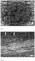
- Fig. 2a is a (inventive) CFRP component (thermoset, prepreg fabric) with KTL layer to see (top view surface).
- Fig. 2b shows a section of a cross section of a (inventive) CFRP component (thermoset, prepreg fabric) with KTL layer.
- KTL paint deposits in areas where the Carbon fibers are located in near-surface areas. That is, there is at least partially also a coating of the matrix material instead (see arrows in Fig. 2b ).
- the CFRP component is not completely coated with KTL, but rather electrochemical selective coating of exposed areas of the carbon fibers and partly of matrix material occurs in areas where carbon fibers lie just below the surface (not in FIG Fig. 2b shown).
- Fig. 3 a diagram is shown which shows the contact corrosion current between (a) a non-inventive KTL-coated CFRP component and a lightweight construction material component (here: AA 2024 clad) or (b) a CFL selectively coated with KTL according to the invention Component and a lightweight construction material component (AA 2024 clad) in 3% NaCl solution.
- the curve "CFRP with KTL (according to the invention)" lies (essentially) on the X-axis of the diagram, ie no contact corrosion current can be detected.
- Example 3 Deposition of copper on exposed areas of the carbon fibers of a CFRP component:
- a CFRP component with exposed regions of the carbon fibers is electroplated by electroplating as follows:
- the electrolytes used are 0.1 mol / l of copper sulfate and 0.5 mol / l of sulfuric acid.
- the following deposition conditions are selected: -300 mVSCE, 10 minutes
- Fig. 4a shows the result of the selective coating, namely the cut edges of a (inventive) CFRP component (thermoset, 0 ° / 90 ° Atlas fabric), wherein the exposed portions of the carbon fibers are selectively coated with a layer (S), which consists of an electrochemical Deposition of copper results.
- a CFRP component thermoset, 0 ° / 90 ° Atlas fabric
- a CFRP member having exposed portions of the carbon fibers is electrochemically electrochemically coated as follows:
- Pyrrole is used as the monomer for forming the polymer layer on the exposed portions of the carbon fibers.
- the following separation conditions are selected: 750 mV SCE , 45 minutes.
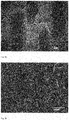
- FIGS. 5a and 5b show plan views of surface sections (5a surface, 5b cut edge) of (inventive) CFRP components, wherein exposed portions of the carbon fibers are selectively coated with a layer (S), wherein the layer (S) consists of polypyrrole.
- the in FIG. 5b shown surface portion results from a cutting edge.
Landscapes
- Chemical & Material Sciences (AREA)
- Engineering & Computer Science (AREA)
- Materials Engineering (AREA)
- Organic Chemistry (AREA)
- Chemical Kinetics & Catalysis (AREA)
- Electrochemistry (AREA)
- Metallurgy (AREA)
- Health & Medical Sciences (AREA)
- Manufacturing & Machinery (AREA)
- Medicinal Chemistry (AREA)
- Polymers & Plastics (AREA)
- Life Sciences & Earth Sciences (AREA)
- Molecular Biology (AREA)
- Wood Science & Technology (AREA)
- Inorganic Chemistry (AREA)
- Laminated Bodies (AREA)
- Reinforced Plastic Materials (AREA)
- Manufacture Of Alloys Or Alloy Compounds (AREA)
Description
- Die vorliegende Erfindung betrifft primär ein Bauteil aus carbonfaserverstärktem Kunststoff (im Folgenden auch "CFK-Bauteil" genannt), bestehend aus oder umfassend ein Matrixmaterial (M) und in das Matrixmaterial (M) eingebettete Carbonfasern,
wobei das Bauteil wenigstens einen Oberflächenabschnitt (A) besitzt,
der einen oder mehrere freiliegende Bereiche der Carbonfasern aufweist,
dadurch gekennzeichnet, dass der bzw. die freiliegende(n) Bereich(e) der Carbonfasern selektiv mit einer Schicht (S) beschichtet ist. bzw. sind,
wobei die Schicht (S) eine Schicht aus Tauchlack, die durch elektrophoretisches Tauchlackieren aufgebracht wurde, oder eine durch Elektropolymerisation hergestellte Schicht ist. - Zudem betrifft die vorliegende Erfindung neue Verfahren zur Herstellung von selektiv beschichteten CFK-Bauteilen, insbesondere von erfindungsgemäßen, selektiv beschichteten CFK-Bauteilen.
- Gemäß einem weiteren Aspekt betrifft die vorliegende Erfindung eine Baugruppe bestehend aus oder umfassend
- (A) ein erfindungsgemäßes Bauteil und
- (B) ein Bauteil umfassend oder bestehend aus einem Material ausgewählt aus der Gruppe bestehend aus Stahl, Eisen, Kupfer, Aluminium, Magnesium und Legierungen davon,
- Weitere Aspekte der vorliegenden Erfindung, insbesondere bevorzugte Ausgestaltungen, ergeben sich aus der nachfolgenden Beschreibung, den Ausführungsbeispielen sowie den beigefügten Patentansprüchen.
- Die Verwendung von CFK-Bauteilen, d. h. von Bauteilen aus carbonfaserverstärktem Kunststoff, ist seit Langem bekannt. Solche Bauteile umfassen in der Regel ein Matrixmaterial, üblicherweise Kunststoff, und in das Matrixmaterial inkorporierte, d. h. eingebettete, Carbonfasern. CFK-Bauteile werden u. a. als hochfeste und hochtemperaturbeständige Verbundwerkstoffe in der Luft- und Raumfahrt sowie der Automobilindustrie eingesetzt. Die zur Herstellung von carbonfaserverstärkten Kunststoffen eingesetzten Fasern werden üblicherweise aus Polyacrylmethyl, Zelluloseacetat oder teerartigen Rückständen der Erdölraffination hergestellt. Die erhaltenen Fasern werden dann üblicherweise stabilisiert (in eine unschmelzbare Form überführt), unter Abspaltung flüchtiger Produkte karbonisiert und graphitisiert. Die graphitisierten Fasern werden üblicherweise vor der Verwendung zur Herstellung von carbonfaserverstärkten Kunststoffen einer (oxidativen) Oberflächenbehandlung unterzogen, um eine bessere Adhäsion zwischen Carbonfaser und Matrixmaterial zu erhalten. Die Carbonfasern werden zur Faserverstärkung von Kunststoffen üblicherweise in Form von Garnen, Bändern, Geweben und dergleichen eingesetzt. Weiterhin werden kurze Carbonfasern auch als Füllstoffe eingesetzt.
- In der Regel besitzen CFK-Bauteile einen oder mehrere freiliegende Bereiche der Carbonfasern, d. h. einen oder mehrere Oberflächenabschnitte an denen Carbonfaserbereiche nicht von Matrixmaterial bedeckt sind. Solche Bereiche resultieren insbesondere aus bei der Herstellung oder der Verarbeitung von CFK-Bauteilen herbeigeführten Schnittkanten, Bohrungen oder sonstigen Verletzungen des Verbundwerkstoffes. Die Carbonfasern unterscheiden sich jedoch in der Regel hinsichtlich chemischer und insbesondere physikalischer Eigenschaften grundlegend von dem Matrixmaterial, so dass solche freiliegenden Bereiche der Carbonfasern bei der weiteren Verarbeitung bzw. Verwendung der CFK-Bauteile häufig besonders berücksichtigt werden müssen. Die Carbonfasern weisen nämlich aufgrund ihrer auf Kohlenstoff basierenden Zusammensetzung ein sehr hohes, mit Edelmetallen vergleichbares Redox-Potential auf, sind besonders leitfähig und unpolar. Hierdurch resultiert (zumindest in einigen Bereichen) eine häufig unerwünschte Leitfähigkeit des Bauteils. Dies führt bei Kontakt solcher CFK-Bauteile mit weiteren Bauteilen, insbesondere Bauteilen umfassend oder bestehend aus Stahl, Eisen oder vor allem metallischen Leichtbaumaterialien wie z. B. Aluminium und Magnesium oder Legierungen davon, häufig korrosionsbedingte Schäden einzelner Bauteile bzw. der gesamten Baugruppe, wenn die freiliegenden Carbonfaserbereiche leitfähig mit anderen Bauteilen verbunden sind. So kann insbesondere beim Fügen von CFK-Bauteilen mit Bauteilen umfassend oder bestehend aus metallischen Materialien wie Stahl, Aluminum und Magnesium bzw. Legierungen davon, das hohe Redox-Potential von Kohlenstoff dazu führen, dass das Korrosionsverhalten der metallischen Materialien wesentlich verändert und unter ungünstigen Bedingungen gegebenenfalls deutlich verschlechtert wird. In einem sich dabei bildenden Kontaktkorrosions-Stromkreis stellen die freiliegenden Bereiche der Carbonfasern aktive Bereiche dar, durch die eine Korrosion der Leichtbaumaterialien verursacht oder verstärkt werden kann.
- CFK-Bauteile mit freiliegenden Bereichen der Carbonfasern weisen zudem den Nachteil auf, dass beispielsweise beim Verbinden eines solchen Bauteils durch Kleben mit einem anderen Bauteil aufgrund der gegenüber dem Matrixmaterial unterschiedlichen Oberflächenenergie dieser freiliegenden Bereiche die Hafteigenschaften des CFK-Bauteils aufgrund dieser freiliegenden Bereiche eingeschränkt bzw. verschlechtert sind, so dass gegebenenfalls keine ausreichende Haftung ermöglicht wird.
- Zudem stellen solche freiliegenden Bereiche der Carbonfasern eine Schwachstelle bezüglich des Alterungsverhaltens von CFK-Bauteilen dar. Denn dort können an der Phasengrenze zwischen Carbonfaser und Matrixmaterial Elektrolyte deutlich schneller ins Innere des Bauteils gelangen und so insgesamt zu einer geringeren Festigkeit des Bauteils führen.
- Im Stand der Technik sind diverse Verfahren beschrieben, die den Ursachen der Kontaktkorrosion bzw. den damit verbundenen Folgen (wie oben beschrieben) zu begegnen versuchen.
- So ist beispielsweise bekannt, Bauteile aus Titan in Kombination mit CFK-Bauteilen einzusetzen, da bei der Verbindung (z.B. durch Fügen) von Titan und CFK keine wie oben beschriebene Korrosion auftritt (vgl. Bennie A. Miller Jr., The galvanic corrosion of graphite epoxy composite materials coupled with alloys, Air Force Insitute of Technology Wright-Patterson Air Force Base, Ohio, 1975, und F. Belucci, Galvanic corrosion between nonmetallic composites and metals: Effect of metal and of temperature, Corrosion Vol. 47, No.10). Ein solches Vorgehen weist jedoch den Nachteil auf, dass hohe Materialkosten anfallen.
- Ein weiterer, im Stand der Technik bekannter Ansatz befasst sich damit, zwischen freiliegenden Bereichen der Carbonfasern von CFK-Bauteilen und etwaigen Bauteilen aus metallischen Materialien (wie oben beschrieben) möglichst große Abstände zu erreichen (vgl. Egon Kunze, Korrosion und Korrosionsschutz, Wiley-VCH, 2001). Solche Abstände bringen jedoch technische und gestalterische Einschränkungen mit sich. Zudem kann der erforderliche Abstand je nach Umgebungsbedingungen, insbesondere je nach Feuchtigkeitszutritt und Salzkonzentration, variieren. Sofern hierbei Titan in Form eines Abstandshalters eingesetzt wird, fallen zudem hohe Materialkosten an.
- Ferner ist im Stand der Technik bekannt, Schnittkanten von CFK-Bauteilen mit Harzen nachzubehandeln, siehe z.B. Merlin D. Danford et al: "Galvanic coupling between D6AC steel, 6061-T6 aluminum, inconel 718, and graphite-epoxy composite material : corrosion occurrence and prevention", 1. Januar 1983 (1983-01-01), http:// ntrs.nasa.gov/archive/nasa/casi.ntrs.nasa.gov/19840005195_1984005195.pdf. Solche Verfahren sind jedoch relativ aufwendig und bieten keine ausreichende, vollständige Sicherheit, dass sämtliche elektrochemisch aktiven, freiliegenden Bereiche der Carbonfasern abgedeckt sind. Zudem haften die Harze zum Teil nicht oder nicht ausreichend auf der Oberfläche des CFK-Bauteils. Des Weiteren wird durch die Nachbehandlung von Schnittkanten mit Harzen häufig die Passgenauigkeit von CFK-Bauteilen, die zur Kombination mit weiteren Bauteilen vorzugsweise erhalten bleiben soll, nachteilig beeinflusst.
- Ein weiterer, im Stand der Technik bekannter Ansatz, eine (Kontakt-)Korrosion zwischen CFK-Bauteil und einem metallischen Bauteil (als Fügepartner) zu vermeiden, besteht darin, den metallischen Fügepartner (umfassend oder bestehend aus z.B. Stahl, Aluminium, Kupfer, Magnesium oder Legierungen davon vollständig oder wenigstens an den Kontaktflächen zu beschichten. Im Falle der Verletzung bzw. Zerstörung einer solchen Beschichtung tritt dann jedoch wiederum eine rasch in die Tiefe gehende Korrosion auf. Zudem wurden bereits diverse Verfahren zur Vorbehandlung der CFK-Bauteil-Oberfläche aus dem Bereich der Kunststofflackierung getestet und adaptiert, um oben genannte (Kontakt-)Korrosion zu vermeiden, aber auch, um der oben genannten Problematik hinsichtlich der verschlechterten Hafteigenschaften von CFK-Bauteilen mit freiliegenden Bereichen der Carbonfasern zu begegnen. In diesem Zusammenhang sind beispielsweise Verfahren wie CO2-Strahlen, Plasmavorbehandlung und Beflammung zu nennen (vgl. Groteklaes, Brock, Mischke, Lehrbuch der Lacktechnologie, Vincentz Verlag, 2000).
- Diese Verfahren bergen jedoch den Nachteil, dass zerstörend auf das CFK-Bauteil eingewirkt wird, wodurch noch mehr Carbonfasern freigelegt werden. Außerdem wird durch keines dieser Verfahren eine vollständige Isolierung der freiliegenden Fasern gewährleistet. Beispielsweise bei einer Plasmavorbehandlung und anschließender Verklebung des CFK- Bauteils mit einem metallischen Kontaktpartner kann es durch unterschiedliche Dicke der Klebstoffschicht zu leitfähigen Kontakten in der Klebfuge kommen.
- Die primäre Aufgabe der vorliegenden Erfindung bestand daher darin, CFK-Bauteile bereitzustellen, bei deren Verwendung sich die vorstehend genannten Probleme bzw. Nachteile vermeiden lassen. Insbesondere sollten Bauteile bereit gestellt werden, welche dauerhaft mit Materialien wie Stahl, Eisen, Kupfer oder insbesondere Leichtbaumaterialien wie Aluminium und Magnesium verbunden bzw. kontaktiert werden können, ohne dass Kontaktkorrosion bzw. ohne dass ein nicht akzeptabler Grad an Kontaktkorrosion auftritt.
- Des Weiteren bestand eine Aufgabe der vorliegenden Erfindung darin, ein Verfahren zur Herstellung solcher Bauteile anzugeben.
- Weitere Aspekte der der vorliegenden Erfindung zugrunde liegenden Aufgabe ergeben sich aus der nachfolgenden Beschreibung sowie insbesondere den beigefügten Patentansprüchen.
- Die primäre Aufgabe der vorliegenden Erfindung wird gelöst durch ein Bauteil aus carbonfaserverstärktem Kunststoff (CFK-Bauteil), bestehend aus oder umfassend ein Matrixmaterial (M) und in das Matrixmaterial (M) eingebettete Carbonfasern, wobei das Bauteil wenigstens einen Oberflächenabschnitt (A) besitzt, der einen oder mehrere freiliegende Bereiche der Carbonfasern aufweist,
dadurch gekennzeichnet, dass der bzw. die freiliegende(n) Bereich(e) der Carbonfasern selektiv mit einer Schicht (S) beschichtet ist bzw. sind, wobei die Schicht (S) eine Schicht aus Tauchlack, die durch elektrophoretisches Tauchlackieren aufgebracht wurde, oder eine durch Elektropolymerisation hergestellte Schicht ist. - Die freiliegenden, erfindungsgemäß selektiv zu beschichtenden Bereiche der Carbonfasern des Oberflächenabschnitts (A) resultieren insbesondere aus bei der Herstellung oder der Verarbeitung von CFK-Bauteilen herbeigeführten Schnittkanten, Bohrungen oder sonstigen Verletzungen des Verbundwerkstoffes (wie einleitend beschrieben).
- Der wenigstens eine Oberflächenabschnitt (A) stellt im Rahmen des vorliegenden Textes einen Oberflächenabschnitt des CFK-Bauteils dar, in welchem ein oder mehrere Bereiche der (im Übrigen in das Matrixmaterial (M) eingebetteten) Carbonfasern nicht von Matrix-material (M) bedeckt sind. Erfindungsgemäß sind diese freiliegenden Bereiche der Carbonfasern selektiv mit einer Schicht (S) beschichtet, wobei die Schicht (S) nicht aus Matrixmaterial (M) besteht.
- Der Begriff "selektiv" ist im Zusammenhang mit der vorliegenden Erfindung so zu verstehen, dass eine zielgerichtete Beschichtung auf dem einen Oberflächenabschnitt (A) eines erfindungsgemäßen Bauteils (sowie gegebenenfalls weiteren Oberflächenabschnitten (A)) erfolgt, wobei im Wesentlichen sämtliche der freiliegenden Bereiche der Carbonfasern mit einer Schicht (S) beschichtet sind, während die übrigen Bereiche des Oberflächenabschnitts (A), d. h. die Bereiche, an denen sich an der Oberfläche des Bauteils Matrixmaterial (M) befindet, im Wesentlichen nicht mit der Schicht (S) beschichtet sind. Dabei kann jedoch auch in geringem Maße insofern eine Beschichtung anderer Bereiche des Oberflächenabschnitts (A), d. h. eine Beschichtung von Matrixmaterial (M) mit einer Schicht (S), erfolgen, als dass bestimmte Verfahren zum selektiven Aufbringen der Schicht (S) auf den freiliegenden Bereichen der Carbonfasern (wie im Folgenden beschrieben) zu einem oder mehreren beschichteten Oberflächenbereichen des Oberflächenabschnitts (A) führen können, der bzw. die (geringfügig) größer ist bzw. sind als der freiliegende, selektiv zu beschichtende Carbonfaser-Bereich selbst. Des Weiteren kann je nach gewähltem Verfahren zur selektiven Beschichtung der freiliegenden Bereiche der Carbonfasern zumindest teilweise auch eine Beschichtung von Matrixmaterial (M) im Oberflächenabschnitt (A) erfolgen, wenn sich unmittelbar unter der dortigen Oberfläche Carbonfasern befinden. Dies gilt insbesondere bei den im Rahmen der vorliegenden Erfindung beschriebenen elektrochemischen Beschichtungs-Methoden. Eine solche Beschichtung des Matrixmaterials (M) kann insbesondere bis zu einer maximalen Entfernung von (unter der Oberfläche liegenden) Carbonfasern zur Oberfläche von etwa 100 µm erfolgen, vor allem bis zu einer maximalen Entfernung von etwa 50 µm.
- Im Zusammenhang mit der vorliegenden Erfindung gilt daher, dass der wenigstens eine Oberflächenabschnitt (A) eines erfindungsgemäßen Bauteils vorzugsweise nicht vollständig mit einer Schicht (S) beschichtet ist. Zumindest gilt jedoch, dass ein erfindungsgemäßes Bauteil nicht vollständig mit einer Schicht (S) beschichtet ist.
- Ein erfindungsgemäßes Bauteil eignet sich aufgrund der selektiven Beschichtung der freiliegenden Carbonfaser-Bereiche vorteilhafterweise besonders gut zur Verwendung in Kombination mit einem oder mehreren weiteren Bauteilen umfassend oder bestehend aus metallischen Materialien wie Stahl, Eisen, Kupfer, Aluminium und Magnesium bzw. Legierungen davon. Denn vorteilhafterweise kann durch eine selektive Beschichtung der freiliegenden Carbonfaser-Bereiche an Oberflächenabschnitten, an welchen das erfindungsgemäße Bauteil mit einem weiteren Bauteil aus metallischem Material (wie oben beschrieben) verbunden ist, das Entstehen eines Kontaktkorrosions-Stromkreises verhindert oder zumindest verzögert werden. Insbesondere kann verhindert werden, dass sich durch freiliegende Bereiche von Carbonfasern aktive Bereiche bilden, durch die eine Kontaktkorrosion der Materialien verursacht oder verstärkt werden kann. Bei einem Oberflächenabschnitt (A) (wie oben beschrieben) handelt es sich demnach vorzugsweise um einen Oberflächenabschnitt, der mit einem Oberflächenabschnitt eines weiteren Bauteils, insbesondere eines Bauteils umfassend oder bestehend aus Materialien wie vorangehend beschrieben, in Kontakt gebracht ist bzw. dazu vorgesehen ist.
- Eine (erfindungsgemäße) selektive Beschichtung bietet (insbesondere gegenüber einer vollständigen Beschichtung) diverse Vorteile, zum Beispiel eine bessere Materialeffizienz und einen geringe(re)n Einfluss auf die Passgenauigkeit und (sonstige) Oberflächeneigenschaften des Bauteils.
- Im Rahmen der vorliegenden Erfindung handelt es sich bei der Schicht (S) um eine mittels elektrochemischem bzw. elektrophoretischem Verfahren (wie hierin beschrieben) aufgebrachte Schicht.
-
- eine Schicht aus Tauchlack, oder
- eine durch Elektropolymerisation hergestellte Schicht.
-
- eine Schicht aus Tauchlack oder
- eine durch Elektropolymerisation hergestellte Schicht
- Eine Schicht aus Tauchlack ist im Rahmen der vorliegenden Erfindung als durch elektrophoretisches Tauchlackieren aufgebrachte Schicht (S) zu verstehen. Details zu kataphoretischem bzw. anaphoretischem Tauchlackieren sind weiter unten beschrieben.
- Unter einer durch Elektropolymerisation hergestellten Schicht ist im Rahmen der vorliegenden Erfindung insbesondere eine Schicht zu verstehen, die durch potentiostatische, galvanostatische oder potentiodynamische Elektropolymerisation aufgebracht ist. Details hierzu sind weiter unten beschrieben.
- Im Ergebnis ist daher ein erfindungsgemäßes Bauteil (wie oben beschrieben) besonders bevorzugt, welches herstellbar ist durch ein Verfahren umfassend folgende Schritte:
- (i) Bereitstellen eines Bauteils aus carbonfaserverstärktem Kunststoff, bestehend aus oder umfassend ein Matrixmaterial (M) und in das Matrixmaterial (M) eingebettete Carbonfasern, wobei das Bauteil wenigstens einen Oberflächenabschnitt (A) besitzt, der einen oder mehrere freiliegende Bereiche der Carbonfasern aufweist, und
- (ii) Beschichten der freiliegenden Bereiche der Carbonfasern mit einer Schicht (S) durch
- (a) elektrophoretisches, insbesondere kataphoretisches oder anaphoretisches Tauchlackieren, vorzugsweise durch kataphoretisches Tauchlackieren,
- (b) potentiostatische, galvanostatische oder potentiodynamische Elektropolymerisation, vorzugsweise potentiostatische Elektropolymerisation,
- Erfindungsgemäß ist es demnach generell besonders bevorzugt, wenn der bzw. die freiliegenden Bereiche der Carbonfasern eines erfindungsgemäßen Bauteils (wie oben beschrieben) selektiv mit einer mittels elektrochemischem/elektrophoretischem Verfahren aufgebrachten Schicht (S) beschichtet ist bzw. sind.
- Ein bevorzugter Aspekt der vorliegenden Erfindung betrifft ein Bauteil (wie oben beschrieben), wobei das Beschichten der freiliegenden Bereiche der Carbonfasern mit einer Schicht (S) durch (a) kataphoretisches oder anaphoretisches Tauchlackieren erfolgt (ist).
- Falls dagegen das CFK-Bauteil vor der selektiven Beschichtung mit einem weiteren Bauteil, insbesondere einem Bauteil umfassend oder bestehend aus Stahl, Eisen, Kupfer oder einem Leichtbaumaterial wie Aluminium oder Magnesium bzw. Legierungen davon, verbunden worden ist, ist im Rahmen der vorliegenden Erfindung das anaphoretische Tauchlackieren zu bevorzugen. Andernfalls, d.h. wenn das CFK-Bauteil allein (selektiv) beschichtet werden soll, ist im Rahmen der vorliegenden Erfindung das kataphoretische Tauchlackieren zu bevorzugen.
- Das grundsätzliche physikalische Prinzip des elektrophoretischen Tauchlackierens, wie es auch im Rahmen der vorliegenden Erfindung Anwendung findet, basiert darauf, dass polymere Materialien kolloidal oder als Partikel in einer wässrigen Lösung (in Form eines Tauchlacks) vorliegen und eine Oberflächenladung aufweisen. Bei diesem Verfahren wird ausgenutzt, dass beim Anlegen einer Gleichspannung mit entsprechendem Vorzeichen an ein leitfähiges Material, das in diesen Tauchlack eingetaucht wird, die geladenen polymeren Materialien zu dem leitfähigen Material wandern. Gleichzeitig laufen an der Oberfläche dieses leitfähigen Materials Reaktionen ab, die zu einer lokalen pH-Wertveränderung führen (beim kataphoretischen Tauchlackieren zu höheren pH-Werten, beim anaphoretischen Tauchlackieren zu niedrigeren pH-Werten). Über die pH-Wertveränderung wird die Abscheidung der polymeren Materialien auf der Oberfläche ausgelöst (Koagulation).
- So wird beim Tauchlackieren üblicherweise ein Elektrotauchsystem verwendet, wobei an ein Werkstück (hier: ein Bauteil mit einem Oberflächenabschnitt (A) mit einem oder mehreren selektiv zu beschichtenden, freiliegenden Bereichen der Carbonfasern) eine Gleichspannung angelegt wird. Das Werkstück ist üblicherweise in ein Bad getaucht, welches ein oder mehrere auf das Werkstück elektrophoretisch aufbringbare polymere Materialien enthält. Diese Materialien werden beim Tauchlackieren durch die starke lokale pH-Wert-Erhöhung (kataphoretisch) bzw. -Erniedrigung (anaphoretisch) im Bereich der freiliegenden Carbonfasern selektiv abgeschieden. Die Abscheidungsparameter werden dabei so gewählt, dass vorzugsweise sämtliche der freiliegenden Bereiche der Carbonfasern des Oberflächenabschnitts (A) bzw., sofern gewünscht, sämtliche der freiliegenden Bereiche der Carbonfasern des gesamten Bauteils mit einer Schicht (S) beschichtet werden, welche aus der elektrophoretischen Abscheidung der vorangehend genannten Materialien resultiert.
- Vorzugsweise wird im Rahmen der vorliegenden Erfindung das Verfahren des Tauchlackierens so lange durchgeführt, bis sich eine Schicht (S) gebildet hat, die selektiv die freiliegenden Bereiche der Carbonfasern derart (isolierend) beschichtet hat, dass keine elektrische Leitfähigkeit mehr erreicht wird bzw. vorhanden ist.
- Gemäß einer weiteren, bevorzugten Ausgestaltung der vorliegenden Erfindung ist die Schicht (S) eine durch Elektropolymerisation aufgebrachte bzw. hergestellte Schicht.
- Dabei umfasst oder besteht die Schicht (S) vorzugsweise aus einem Polymer, das aus einer monomeren Einheit, ausgewählt aus der Gruppe bestehend aus Pyrrol, Thiophen, Anilin, Furan, Phenol, Azulen, Carbazol und Derivate davon, aufgebaut ist oder eine solche umfasst.
- Die Elektropolymerisation ist ein Prozess bei dem durch Anlegen eines Potentials und/oder durch Elektrolyse eine Polymerisationsreaktion eines oder mehrerer (organischer) Monomere zu einem Polymer erzwungen wird. Die Elektropolymerisation ist dabei von geläufigen Filmbildungsreaktionen wie Polyaddition, Polykondensation oder der radikalisch fortlaufenden Polymerisation zu unterscheiden.
- Im Rahmen der vorliegenden Erfindung erfolgt die Elektropolymerisation vorzugsweise auf potentiostatischem, galvanostatischem oder potentiodynamischem Wege.
- Besonders bevorzugt ist die potentiostatische Elektropolymerisation. Dabei werden monomere Ausgangsmoleküle (z. B. Pyrrol, Thiophen, Anilin, Furan, Phenol, Azulen oder Carbazol, vorzugsweise Pyrrol oder Thiophen, besonders bevorzugt Pyrrol) an einer Arbeitselektrode in einer elektrochemischen Zelle oxidiert. Bei dieser Methode werden vorzugsweise die selektiv zu beschichtenden freiliegenden Bereiche der Carbonfasern als Arbeitselektrode bevorzugt in einem drei-Elektrodenaufbau integriert. Die beiden weiteren Elektroden sind gemäß bevorzugter Ausgestaltung eine Gegenelektrode, beispielsweise aus Platin (z.B. in Form eines Netzes), und eine Bezugselektrode (z. B. eine Kalomel- oder eine Silber/Silberchlorid-Elektrode). Mittels eines Potentiostaten können die gewünschten Potentialdifferenzen eingestellt werden. Die anzulegende Spannung liegt vorzugsweise oberhalb des kritischen Oxidationspotentials des eingesetzten bzw. eines oder mehrerer der eingesetzten Monomere. Im Ergebnis wird im Rahmen der (potentiostatischen) Elektropolymerisation durch die elektrochemische Oxidation des bzw. der monomeren Einheiten eine elektrochemische Polymerisation auf den freiliegenden Bereichen der Carbonfasern, d. h. der Arbeitselektrode, bewirkt. Der Mechanismus der Elektropolymerisation ist noch nicht bis in alle Details geklärt. Es wird jedoch angenommen, dass hierbei zunächst aus (ungeladenen) Monomeren (je nach Verfahrensgestaltung geladene) Radikale gebildet werden, die dann durch Dimerisierung und anschließende Deprotonierung wiederum neutrale konjugierte Dimere (Moleküle aus zwei Basiseinheiten) bilden. Dieser Zyklus der Radikalbildung, des Kettenwachstums und der anschließenden Deprotonierung wiederholt sich zyklisch mit den vorliegenden Monomeren und deren Polymerisationsprodukten solange das Oxidationspotential an der Arbeitselektrode anliegt. Dabei können an der Arbeitselektrodenoberfläche nicht nur monomere Radikale gebildet werden, sondern auch deren Dimere, Trimere, Tetramere und weitere auf der Basis der eingesetzten Monomere gebildete höhere Homologen bzw. Polymerisationsprodukte. Die so gebildeten Radikale reagieren (beliebig) untereinander und führen zu einem hohen Kettenwachstum an der Arbeitselektrodenoberfläche. Auf diese Weise wird ein hoch molekulares Netzwerk hergestellt, das sich ab einer kritischen Größe auf der Arbeitselektrode abscheidet. Die kritische Größe, welche sich durch die Anzahl der einzelnen Monomereinheiten im Gesamtmolekül definiert, hängt dabei von Temperatur, pH-Wert und Zusammensetzung der Abscheidungslösung ab. Im Ergebnis erfolgt ein Aufwachsen eines Polymers (z. B. Polypyrrol) auf den freiliegenden Bereichen der Carbonfasern, so dass die freiliegenden Bereiche der Carbonfasern (elektrochemisch) selektiv beschichtet werden.
- Im Rahmen der vorliegenden Erfindung ist es bei Durchführung der (potentiostatischen) Elektropolymerisation vorteilhafterweise möglich, sowohl aus nichtwässrigen, als auch aus wässrigen Bädern Polymere, z.B. Polypyrrol, auf den freiliegenden Bereich der Carbonfasern abzuscheiden. Weitere Bestandteile können je nach Bad
- Colöser, wie Alkohole, Ester, Ketone oder Ether,
- anorganische oder organische Leitsalze sowie gegebenenfalls
- weitere (Zusatz-)Bestandteile, z. B. Additive oder Katalysatoren (z. B. NaBr), sein.
- Sofern Pyrrol oder Thiophen als Monomere im Rahmen der (vorzugsweise potentiostatischen) Elektropolymerisation eingesetzt werden, wird vorzugsweise eine Potentialdifferenz im Bereich von 600 mV bis 1300 mV (gegenüber einer Kalomel-Bezugselektrode) gewählt. Besonders bevorzugt ist bei Verwendung von Pyrrol als Monomer eine Potentialdifferenz im Bereich von etwa 650 mV (gegenüber einer Kalomel-Bezugselektrode). Bei der Verwendung von Thiophen als Monomer ist besonders bevorzugt eine Potentialdifferenz im Bereich von etwa 1200 mV (gegenüber einer Kalomel-Bezugselektrode) zu verwenden.
- Besonders bevorzugt ist ein pulsartiges Anlegen des (Oxidations-)Potentials, wobei vorzugsweise eine Pause von jeweils etwa 20 Sekunden zwischen den Abscheidungen gewählt wird. Hierdurch werden vorteilhafterweise besonders homogene Schichten (S) erhalten.
- Die Dicke der Schicht (S) lässt sich bei der Elektropolymerisation grundsätzlich durch die Dauer des angelegten Potentials steuern.
- Zusammenfassend ist es besonders bevorzugt, wenn das Beschichten der freiliegenden Bereiche der Carbonfasern mit einer Schicht (S) durch potentiostatische Elektropolymerisation erfolgt, wobei ein oder mehrere Monomere ausgewählt aus der Gruppe bestehend aus Pyrrol, Thiophen, Anilin, Furan, Phenol, Azulen, Carbazol und Derivate davon, sowie gegebenenfalls weitere Monomere verwendet werden. Besonders bevorzugt wird bzw. werden Pyrrol und/oder Thiophen als Monomere verwendet.
- Weiter bevorzugt ist ein erfindungsgemäßes Bauteil (wie oben beschrieben), wobei die Schicht (S) eine mittlere Dicke im Bereich von 0,1 bis 200 µm, vorzugsweise von 1 bis 60 µm, besitzt.
- Sofern die Schicht (S) eine Schicht aus Tauchlack ist (wie oben beschrieben), besitzt diese eine mittlere Dicke im Bereich von 1 bis 200 µm, vorzugsweise von 10 bis 60 µm.
- Sofern die Schicht (S) eine durch Polymerisation hergestellte Schicht ist (wie oben beschrieben), besitzt diese vorzugsweise eine mittlere Dicke im Bereich von 0,1 bis 100 µm, vorzugsweise von 1 bis 50 µm.
- Besonders bevorzugt ist ein erfindungsgemäßes Bauteil (wie oben beschrieben), wobei das Matrixmaterial (M) ausgewählt ist aus der Gruppe bestehend aus Duroplaste, insbesondere Epoxide, Polyurethane, Polyimide, Phenol-Formaldehydkondensationsharze, ungesättigte Polyester, Vinylesterharze, und Thermoplaste, insbesondere Polyaryletherketone, Polyarylethersulfone, Polypropylen, Polyamide und Polyester.
- Bei dem (erfindungsgemäßen) Bauteil kann es sich um ein Bauteil beliebiger Form (z.B. Platten oder Hohlprofile) handeln. Halbzeug ist jedoch erfindungsgemäß weniger bevorzugt.
- Ein weiterer Aspekt der vorliegenden Erfindung betrifft ein Verfahren zur Herstellung eines Bauteils aus carbonfaserverstärktem Kunststoff (CFK-Bauteil), vorzugsweise eines erfindungsgemäßen Bauteils wie oben beschrieben, besonders bevorzugt eines erfindungsgemäßen Bauteils, wie vorangehend als bevorzugt bezeichnet, wobei das Verfahren folgende Schritte umfasst:
- (i) Bereitstellen eines Bauteils aus carbonfaserverstärktem Kunststoff, bestehend aus oder umfassend ein Matrixmaterial (M) und in das Matrixmaterial (M) eingebettete Carbonfasern, wobei das Bauteil wenigstens einen Oberflächenabschnitt (A) besitzt, der einen oder mehrere freiliegende Bereiche der Carbonfasern aufweist, und
- (ii) Beschichten der freiliegenden Bereiche der Carbonfasern mit einer Schicht (S) durch
- (a) elektrophoretisches Tauchlackieren (siehe hierzu oben), vorzugsweise durch kataphoretisches Tauchlackieren, oder
- (b) Elektropolymerisation, vorzugsweise potentiostatische, galvanostatische oder potentiodynamische Elektropolymerisation, besonders bevorzugt potentiostatische Elektropolymerisation,
- Für die bevorzugten Ausgestaltungen der Schritte (i) und (ii) gilt das vorangehend Gesagte entsprechend.
- Dementsprechend ist es gemäß einer Ausgestaltung des erfindungsgemäßen Verfahrens bevorzugt, wenn das Beschichten der freiliegenden Bereiche der Carbonfasern mit einer Schicht (S) durch (a) kataphoretisches Tauchlackieren (wie oben beschrieben) erfolgt. Dabei gilt das vorangehend im Zusammenhang mit dem Tauchlackieren Gesagte entsprechend.
- Gemäß einer weiteren Ausgestaltung des erfindungsgemäßen Verfahrens ist es besonders bevorzugt, wenn das Beschichten der freiliegenden Bereiche der Carbonfasern mit einer Schicht (S) durch (c) potentiostatische Elektropolymerisation erfolgt, vorzugsweise durch potentiostatische Elektropolymerisation unter Verwendung eines Monomers ausgewählt aus der Gruppe bestehend aus Pyrrol, Thiophen, Anilin, Furan, Phenol, Azulen, Carbazol und Derivate davon, so dass eine Schicht (S) erhalten wird, die ein Polymer umfasst oder daraus besteht, das aus einer monomeren Einheit, ausgewählt aus der Gruppe bestehend aus Pyrrol, Thiophen, Anilin, Furan, Phenol, Azulen, Carbazol und Derivate davon, aufgebaut ist oder eine solche umfasst.
- Das Matrixmaterial (M) ist vorzugsweise ausgewählt aus der Gruppe bestehend aus Duroplaste, insbesondere Epoxide, Polyurethane, Polyimide, Phenol-Formaldehydkondensationsharze, ungesättigte Polyester, Vinylesterharze, und Thermoplaste, insbesondere Polyaryletherketone, Polyarylethersulfone, Polypropylen, Polyamide und Polyester.
- Wie oben beschrieben, eignet sich ein erfindungsgemäßes Bauteil insbesondere zur Kombination mit einem oder mehreren weiteren Bauteilen umfassend oder bestehend aus einem Material wie zum Beispiel Stahl, Eisen, Kupfer, Aluminium oder Magnesium bzw. Legierungen davon.
- Dementsprechend betrifft ein weiterer Aspekt der vorliegenden Erfindung eine Baugruppe bestehend aus oder umfassend
- (A) ein erfindungsgemäßes Bauteil, vorzugsweise ein erfindungsgemäßes Bauteil wie vorangehend als bevorzugt bezeichnet, und
- (B) ein Bauteil umfassend oder bestehend aus einem Material ausgewählt aus der Gruppe bestehend aus Stahl, Eisen, Kupfer, Aluminium und Magnesium und Legierungen davon, vorzugsweise umfassend oder bestehend aus einem Leichtbaumaterial ausgewählt aus der Gruppe bestehend aus Aluminium und Magnesium und Legierungen davon, wobei das Bauteil gemäß (A) und das Bauteil gemäß (B), vorzugsweise über eine oder mehrere Kontaktflächen, (direkt) miteinander verbunden sind (z.B. durch Fügen, insbesondere durch Kleben und/oder Nieten).
- Dabei weisen die Kontaktflächen vorzugsweise einen oder mehrere Oberflächenabschnitte (A) auf, an denen die freiliegenden Bereiche der Carbonfasern selektiv mit einer Schicht (S) beschichtet sind (wie vorangehend beschrieben).
- Vorteilhafterweise kann durch die selektive Beschichtung der freiliegenden Carbonfaser-Bereiche, insbesondere der freiliegenden Carbonfaser-Bereiche auf den Kontaktflächen an denen das erfindungsgemäße Bauteil (A) mit dem weiteren Bauteil (B) (wie oben beschrieben) zu verbinden ist, das Entstehen eines Kontaktkorrosions-Stromkreises verhindert oder zumindest verzögert werden. Insbesondere kann verhindert werden, dass sich durch freiliegende Bereiche von Carbonfasern aktive Bereiche bilden, durch die eine Kontaktkorrosion der oben genannten Materialien des weiteren Bauteils (B) verursacht oder verstärkt werden kann.
- Die Bauteile (A) und (B) sowie gegebenenfalls weiteren Bauteile einer erfindungsgemäßen Baugruppe sind gemäß einer bevorzugten Ausgestaltung der vorliegenden Erfindung furch Fügen mittels dem Fachmann bekannten Verfahren miteinander verbunden.
- Die selektive Beschichtung der freiliegenden Bereiche der Carbonfasern des Bauteils (A) kann erfindungsgemäß vor und/oder nach dem Verbinden der Bauteile (A) und (B) erfolgen.
- Im Folgenden wird die vorliegende Erfindung anhand von Beispielen näher erläutert.
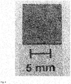
- Ein nicht erfindungsgemäß beschichtetes CFK-Bauteil wird leitfähig mit einem Bauteil aus Leichtbaumaterial, nämlich einem Bauteil aus einer Aluminiumlegierung (Al 99,5), kontaktiert und für 200 Stunden im Salzsprühnebeltest gelagert.
- Das Ergebnis des Salzsprühnebeltests ist in
Fig. 1 gezeigt. - Nach 200 Stunden im Salzsprühnebeltest kann eine verstärkte bzw. beschleunigte Korrosion des Leichtbaumaterials durch Kontakt mit CFK beobachtet werden (siehe Pfeile in
Fig. 1 ). - Ein CFK-Bauteil mit freiliegenden Bereichen von Carbonfasern wird mit einem kataphoretischen Tauchlack (KTL; hier: BASF Cathoguard 310 Elektrotauchlack) beschichtet.
BASF Cathoguard 310 Elektrotauchlack: Bestandteil: Beschreibung: Masse [g] VE-Wasser 433 SC 18-0110 Essigsäure, 10%ig 4 FT 23-0303 Bindemittel 451 FT 24-7328 Pigmentpaste 112 - Folgende Abscheidebedingungen werden gewählt: 250 V, 30 °C, 150 s.
- Folgende Einbrennbedingungen werden gewählt: 15 Min., 175 °C.
- Das Resultat ist ein (erfindungsgemäßes) CFK-Bauteil, wobei die freiliegenden Bereiche der Carbonfasern selektiv mit einer Schicht (S) beschichtet sind. Ein solches Bauteil weist eine besonders gute Benetzbarkeit auf und eignet sich aufgrund der selektiven Beschichtung besonders gut zur Kombination (z.B. durch Fügen) mit einem oder mehreren weiteren Bauteilen bestehend aus oder umfassend Leichtbaumaterialien wie Aluminium, Magnesium oder Legierungen davon.
- In
Fig. 2a ist ein (erfindungsgemäßes) CFK-Bauteil (Duroplast, Prepreg-Gewebe) mit KTL-Schicht zu sehen (Draufsicht Oberfläche). -
Fig. 2b zeigt einen Ausschnitt eines Querschnitts eines (erfindungsgemäßen) CFK-Bauteils (Duroplast, Prepreg-Gewebe) mit KTL-Schicht. AusFig. 2b (1=KTL-Lack, 2=Bereiche ohne Carbonfasern, 3=Carbonfasern, 4=Carbonfasern) ist ersichtlich, dass sich der KTL-Lack, wie auch im Rahmen der vorstehenden Beschreibung erläutert, teilweise auch in Bereichen abscheidet, bei denen sich die Carbonfasern in oberflächennahen Bereichen befinden. D.h., es findet zumindest teilweise auch eine Beschichtung des Matrixmaterials statt (siehe Pfeile inFig. 2b ). Das CFK-Bauteil ist jedoch nicht vollständig mit KTL beschichtet, sondern vielmehr findet eine elektrochemische, selektive Beschichtung von freiliegenden Bereichen der Carbonfasern sowie teilweise von Matrixmaterial in Bereichen, bei denen unmittelbar unter Oberfläche Carbonfasern liegen, statt (nicht inFig. 2b gezeigt). - In
Fig. 3 ist ein Diagramm gezeigt, welches den Kontaktkorrosionsstrom zwischen (a) einem (nicht erfindungsgemäßen) nicht mit KTL beschichteten CFK-Bauteil und einem Bauteil aus Leichtbaumaterial (hier: AA 2024 clad) bzw. (b) einem (erfindungsgemäßen) selektiv mit KTL beschichteten CFK-Bauteil und einem Bauteil aus Leichtbaumaterial (AA 2024 clad) in 3 %iger NaCl-Lösung zeigt. Die Kurve "CFK mit KTL (erfindungsgemäß)" (betreffend vorstehende Alternative (b)) liegt dabei (im Wesentlichen) auf der X-Achse des Diagramms, d.h. es ist kein Kontaktkorrosionsstrom feststellbar. - Ein CFK-Bauteil mit freiliegenden Bereichen der Carbonfasern wird wie folgt elektrochemisch mittels galvanischer Abscheidung beschichtet:
- Als Elektrolyte werden 0,1 mol/l Kupfersulfat und 0,5 mol/l Schwefelsäure eingesetzt.
- Folgende Abscheidebedingungen werden gewählt: -300 mVSCE, 10 Minuten
-
Fig. 4a zeigt das Resultat der selektiven Beschichtung, nämlich die Schnittkanten eines (erfindugnsgemäßen) CFK-Bauteils (Duroplast, 0°/90° Atlas-Gewebe), wobei die freiliegenden Bereiche der Carbonfasern selektiv mit einer Schicht (S) beschichtet sind, welche aus einer elektrochemischen Abscheidung von Kupfer resultiert. - Ein CFK-Bauteil mit freiliegenden Bereichen der Carbonfasern wird wie folgt elektrochemisch mittels Elektropolymerisation beschichtet:
- Als Monomer zum Aufbau der Polymerschicht auf den freiliegenden Bereichen der Carbonfasern wird Pyrrol verwendet.
- Folgende Abscheidebedingungen werden gewählt: 750 mVSCE, 45 Minuten.
- Die
Figuren 5a und 5b zeigen Draufsichten von Oberflächen-Ausschnitten (5a Oberfläche, 5b Schnittkante) von (erfindungsgemäßen) CFK-Bauteilen, wobei freiliegende Bereiche der Carbonfasern selektiv mit einer Schicht (S) beschichtet sind, wobei die Schicht (S) aus Polypyrrol besteht. Der inFigur 5b gezeigte Oberflächenabschnitt resultiert aus einer Schnittkante.
Claims (11)
- Bauteil aus carbonfaserverstärktem Kunststoff, bestehend aus oder umfassend ein Matrixmaterial (M) und in das Matrixmaterial (M) eingebettete Carbonfasern,
wobei das Bauteil wenigstens einen Oberflächenabschnitt (A) besitzt, der einen oder mehrere freiliegende Bereiche der Carbonfasern aufweist, dadurch gekennzeichnet, dass der bzw. die freiliegende(n) Bereich(e) der Carbonfasern selektiv mit einer Schicht (S) beschichtet ist bzw. sind,
wobei die Schicht (S)- eine durch elektrophoretisches Tauchlackieren aufgebrachte Schicht aus Tauchlack oder- eine durch Elektropolymerisation hergestellte Schicht ist. - Bauteil nach Anspruch 1,
wobei das Beschichten der freiliegenden Bereiche der Carbonfasern mit einer Schicht (S) durch elektrophoretisches Tauchlackieren erfolgt. - Bauteil nach Anspruch 1,
wobei die Schicht (S) eine durch Elektropolymerisation hergestellte Schicht ist und ein Polymer umfasst oder daraus besteht, das aus einer monomeren Einheit ausgewählt aus der Gruppe bestehend aus Pyrrol, Thiophen, Anilin, Furan, Phenol, Azulen, Carbazol und Derivate davon, aufgebaut ist oder eine solche umfasst. - Bauteil nach einem der vorangehenden Ansprüche, wobei die Schicht (S) eine mittlere Dicke im Bereich von 0,1 bis 200 µm besitzt.
- Bauteil nach Anspruch 4, wobei die Schicht (S)- eine Schicht aus Tauchlack ist und eine mittlere Dicke im Bereich von 1 bis 200 µm, vorzugsweise im Bereich von 10 bis 60 µm, besitzt, oder- eine durch Elektropolymerisation hergestellte Schicht ist und eine mittlere Dicke Im Bereich von 0,1 bis 100 µm, vorzugsweise im Bereich von 1 bis 50 µm, besitzt.
- Bauteil nach einem der vorangehenden Ansprüche, wobei das Matrixmaterial (M) ausgewählt ist aus der Gruppe bestehend aus Duroplaste, insbesondere Epoxide. Polyurethane, Polyimide, Phenol-Formaldehydkondensationsharze, ungesättigte Polyester, Vinylesterharze, und Thermoplaste, insbesondere Polyaryletherketone, Polyarylethersulfone, Polypropylen, Polyamide und Polyester.
- Verfahren zur Herstellung eines Bauteils aus carbonfaserverstärktem Kunststoff umfassend die Schritte:(i) Bereitstellen eines Bauteils aus carbonfaserverstärktem Kunststoff, bestehend aus oder umfassend ein Matrixmaterial (M) und in das Matrixmaterial (M) eingebettete Carbonfasern, wobei das Bauteil wenigstens einen Oberflächenabschnitt (A) besitzt, der einen oder mehrere freiliegende Bereiche der Carbonfasern aufweist, und(ii) Beschichten der freiliegenden Bereiche der Carbonfasern mit einer Schicht (S) durch(a) elektrophoretisches Tauchlackieren oder(b) potentiostatische, galvanostatische oder potentiodynamische Elektropolymerisation,
so dass die freiliegenden Bereiche der Carbonfasern des wenigstens einen Oberflächenabschnitts (A) selektiv mit einer Schicht (S) beschichtet werden. - Verfahren nach Anspruch 7,
wobei das Beschichten der freiliegenden Bereiche der Carbonfasern mit einer Schicht (S) durch (a) kataphoretisches Tauchlackieren erfolgt. - Verfahren nach Anspruch 8,
wobei das Beschichten der freiliegenden Bereiche der Carbonfasern mit einer Schicht (S) durch (c) potentiostatische Elektropolymerisation unter Verwendung eines oder mehrerer Monomere ausgewählt aus der Gruppe bestehend aus Pyrrol, Thiophen, Anilin, Furan, Phenol, Azulen, Carbazol und Derivate davon, erfolgt,
so dass eine Schicht (S) erhalten wird, die ein Polymer umfasst oder daraus besteht, das aus einer monomeren Einheit ausgewählt aus der Gruppe bestehend aus Pyrrol, Thiophen, Anilin, Furan, Phenol, Azulen, Carbazol und Derivate davon, aufgebaut ist oder eine solche umfasst. - Verfahren nach einem der Ansprüche 7 bis 9,
wobei das Matrixmaterial (M) ausgewählt ist aus der Gruppe bestehend aus Duroplaste, insbesondere Epoxide, Polyurethane, Polyimide, Phenol-Formaldehydkondensationsharze, ungesättigte Polyester, Vinylesterharze, und Thermoplaste, insbesondere Polyarylotherketone, Polyarylethersulfone, Polypropylen, Polyamide und Polyester, - Baugruppe bestehend aus oder umfassend(A) ein Bauteil nach einem der Ansprüche 1 bis 6 und(B) ein Bauteil umfassend oder bestehend aus einem Material ausgewählt aus der Gruppe bestehend aus Stahl, Eisen, Kupfer, Aluminium, Magnesium und Legierungen davon,wobei das Bauteil gemäß (A) und das Bauteil gemäß (B), vorzugsweise über eine oder mehrere Kontaktflächen, miteinander verbunden sind.
Applications Claiming Priority (2)
| Application Number | Priority Date | Filing Date | Title |
|---|---|---|---|
| DE102011004801A DE102011004801B4 (de) | 2011-02-25 | 2011-02-25 | Selektiv beschichtete CFK-Bauteile und Verfahren zu deren Herstellung |
| PCT/EP2012/053196 WO2012113926A2 (de) | 2011-02-25 | 2012-02-24 | Selektiv beschichtete cfk-bauteile und verfahren zu deren herstellung |
Publications (2)
| Publication Number | Publication Date |
|---|---|
| EP2678463A2 EP2678463A2 (de) | 2014-01-01 |
| EP2678463B1 true EP2678463B1 (de) | 2016-12-28 |
Family
ID=45814482
Family Applications (1)
| Application Number | Title | Priority Date | Filing Date |
|---|---|---|---|
| EP12708102.4A Not-in-force EP2678463B1 (de) | 2011-02-25 | 2012-02-24 | Selektiv beschichtete cfk-bauteile und verfahren zu deren herstellung |
Country Status (4)
| Country | Link |
|---|---|
| US (1) | US9562301B2 (de) |
| EP (1) | EP2678463B1 (de) |
| DE (1) | DE102011004801B4 (de) |
| WO (1) | WO2012113926A2 (de) |
Families Citing this family (7)
| Publication number | Priority date | Publication date | Assignee | Title |
|---|---|---|---|---|
| EP2689919B1 (de) * | 2012-07-24 | 2020-04-08 | Airbus Operations GmbH | Verfahren zur selektiven Isolierung von CFRP-Teilen durch Elektroablagerungsbeschichtungen |
| DE102012213455B4 (de) * | 2012-07-31 | 2022-03-03 | Bayerische Motoren Werke Aktiengesellschaft | Verfahren zur Bildung einer Korrosionsschutzschicht an der Oberfläche eines CFK-Bauteils |
| DE102012112821A1 (de) * | 2012-12-20 | 2014-06-26 | Thyssenkrupp Steel Europe Ag | Halbzeug für Hybrid-Bauteile, Hybrid-Bauteil und Verfahren zur Herstellung eines Halbzeugs |
| DE102014000908A1 (de) * | 2014-01-28 | 2015-07-30 | Airbus Ds Gmbh | Thermisches Verbindungselement und Verfahren zu dessen Herstellung |
| MX2021009522A (es) | 2019-02-08 | 2021-09-08 | Ppg Ind Ohio Inc | Metodos para recubrir materiales que contienen fibra y materiales recubiertos que contienen fibra. |
| LU101217B1 (de) * | 2019-05-15 | 2020-11-16 | Airbus Operations Gmbh | Fasermetallaminate mit elektrisch isolierten kohlenstoffasern |
| WO2024176119A1 (en) * | 2023-02-21 | 2024-08-29 | Tata Motors Limited | Method of adhesion of high emissivity material to surface |
Family Cites Families (21)
| Publication number | Priority date | Publication date | Assignee | Title |
|---|---|---|---|---|
| USH1682H (en) * | 1996-05-28 | 1997-10-07 | The United States Of America As Represented By The Secretary Of The Air Force | Method for producing ceramic coatings on fibers |
| DE2821047A1 (de) * | 1978-05-13 | 1979-11-22 | Messerschmitt Boelkow Blohm | Hohler schichtkoerper |
| US4397901A (en) * | 1979-07-31 | 1983-08-09 | Warren James W | Composite article and method of making same |
| US4272346A (en) * | 1979-12-03 | 1981-06-09 | Washington State University Research Foundation | Treatment of carbon fibers to decrease electrical hazards of conductive fiber fragment release |
| US4321298A (en) * | 1980-02-26 | 1982-03-23 | Hitco | Carbon fabrics sequentially resin coated with (1) a metal-containing composition and (2) a boron-containing composition are laminated and carbonized |
| DE3136283C1 (de) * | 1981-09-12 | 1983-02-03 | Nukem Gmbh, 6450 Hanau | Verfahren zum Metallisieren kohlefaserverstaerkter Kunststoffteile |
| US4476164A (en) * | 1982-06-24 | 1984-10-09 | United Technologies Corporation | Deposition of improved SiC coatings on carbon-base materials |
| US4983463A (en) * | 1987-08-12 | 1991-01-08 | United Technologies Corporation | Hybrid composite structures of fiber reinforced glass and resin matrices |
| US5419927A (en) * | 1988-09-26 | 1995-05-30 | Chromalloy Gas Turbine Corporation | Process for coating fiber reinforced ceramic composites |
| JPH0724328B2 (ja) * | 1989-07-03 | 1995-03-15 | ポリプラスチックス株式会社 | 精密細線回路用成形品の製造方法 |
| US5254397A (en) * | 1989-12-27 | 1993-10-19 | Sumitomo Electric Industries, Ltd. | Carbon fiber-reinforced composite material having a gradient carbide coating |
| US5039550A (en) * | 1990-01-23 | 1991-08-13 | The United States Of America As Represented By The Secretary Of Commerce | Colloidal processing method for coating ceramic reinforcing agents |
| JPH0474868A (ja) * | 1990-07-13 | 1992-03-10 | Kanou Shoji Kk | 繊維強化プラスチック構造体のめっき方法 |
| US5302319A (en) * | 1991-01-07 | 1994-04-12 | United Technologies Corporation | Preparation of sol gel composition for electrophoresis |
| US5468358A (en) * | 1993-07-06 | 1995-11-21 | General Atomics | Fabrication of fiber-reinforced composites |
| US5716677A (en) * | 1996-03-21 | 1998-02-10 | Ohio Aerospace Institute | Protective coatings for polyimide composites |
| GB0102896D0 (en) * | 2001-02-06 | 2001-03-21 | Univ Greenwich | Improved electrophoretic deposition |
| FR2858624B1 (fr) * | 2003-08-08 | 2005-09-09 | Rhodia Engineering Plastics Sa | Composition electrostatique a base de matrice polyamide |
| DE102006046518B4 (de) * | 2006-09-29 | 2008-10-30 | Airbus Deutschland Gmbh | Verfahren zum Beschichten eines Substrates |
| DE102007029337B4 (de) * | 2007-06-26 | 2010-07-22 | Airbus Deutschland Gmbh | Korrosionsfeste Verbindung zwischen einem ersten Bauteil und einem zweiten Bauteil |
| US8023267B2 (en) | 2009-06-19 | 2011-09-20 | General Electric Company | Avionics chassis |
-
2011
- 2011-02-25 DE DE102011004801A patent/DE102011004801B4/de not_active Expired - Fee Related
-
2012
- 2012-02-24 WO PCT/EP2012/053196 patent/WO2012113926A2/de not_active Ceased
- 2012-02-24 US US14/001,046 patent/US9562301B2/en not_active Expired - Fee Related
- 2012-02-24 EP EP12708102.4A patent/EP2678463B1/de not_active Not-in-force
Non-Patent Citations (1)
| Title |
|---|
| None * |
Also Published As
| Publication number | Publication date |
|---|---|
| WO2012113926A2 (de) | 2012-08-30 |
| WO2012113926A4 (de) | 2013-07-11 |
| US20140037919A1 (en) | 2014-02-06 |
| WO2012113926A3 (de) | 2013-05-10 |
| DE102011004801B4 (de) | 2013-11-07 |
| US9562301B2 (en) | 2017-02-07 |
| DE102011004801A1 (de) | 2012-08-30 |
| EP2678463A2 (de) | 2014-01-01 |
Similar Documents
| Publication | Publication Date | Title |
|---|---|---|
| DE102011004801B4 (de) | Selektiv beschichtete CFK-Bauteile und Verfahren zu deren Herstellung | |
| EP2139675B1 (de) | Wartungsfreies gleitlager | |
| EP0616558B1 (de) | Verfahren zur beschichtung von oberflächen mit feinteiligen feststoff-partikeln | |
| DE102016222943B3 (de) | Metallisierte Oberflächen und Verfahren zu ihrer Herstellung | |
| EP2279280A2 (de) | Verfahren zum beschichten eines faserverbundbauteils für ein luft- oder raumfahrzeug und durch ein derartiges verfahren hergestelltes faserverbundbauteil | |
| DE1771323A1 (de) | Verfahren zum UEberziehen von Mctalloberflaechen mit einem fluorhaltigen Polymer | |
| DE4323480C2 (de) | Verfahren zum Pulverlackieren von Verbundprofilen sowie Verbundprofil | |
| DE102012001859B4 (de) | Verbindungsanordnung und Verfahren zum Verbinden wenigstens eines ersten Bauteils aus einem kohlefaserverstärkten Verbundwerkstoff mit wenigstens einem zweiten Bauteil | |
| EP2052013B1 (de) | Verfahren zum verbinden von kunststoffteilen elektrischer oder elektronischer bauteile | |
| DE102011075926A1 (de) | Hybridbauteil und Verfahren zur Herstellung eines Hybridbauteils | |
| DE102016119190B4 (de) | Beschichtungsverfahren für plattierten Stahl und Beschichtungslösung zum Beschichten plattierten Stahls | |
| EP2774745B1 (de) | Verfahren zum Fügen faserverstärkter thermoplastischer Kunststoffteile | |
| DE69635600T2 (de) | Harzzusammensetzung für stromlose Metallabscheidung und Verfahren zur stromlosen Metallabscheidung | |
| EP2307593A2 (de) | Verbundwerkstoff | |
| WO2004035857A2 (de) | Plasmapolymere haftschichten | |
| EP1223188A1 (de) | Verfahren zur Herstellung von zur Pulverlackierung vorgesehener Kunstoffprofile | |
| EP3336135A1 (de) | Verfahren zur modifizierung von kunststoffoberflächen | |
| EP2934879B1 (de) | Halbzeug für hybrid-bauteile, hybrid-bauteil und verfahren zur herstellung eines halbzeugs | |
| DE102008048020A1 (de) | Gleitlager | |
| DE102016201951A1 (de) | Hybridbauteil und Verfahren zur Herstellung eines Hybridbauteils | |
| EP3368272B1 (de) | Metall-kunststoff-verbundbauteil und verfahren zur herstellung eines solchen verbundbauteils | |
| DE102009042574A1 (de) | Endisolierung von Baugruppen | |
| DE102011112758A1 (de) | Schutzschicht | |
| WO2004056561A1 (de) | Verfahren zur beschichtung zu lackierender bauteile aus faserverstärktem kunststoff | |
| DE10028705A1 (de) | Verfahren zur Herstellung eines mit mindestens zwei unterschiedlichen Lacken beschichteten Karosserieelementes eines Kraftfahrzeugs |
Legal Events
| Date | Code | Title | Description |
|---|---|---|---|
| PUAI | Public reference made under article 153(3) epc to a published international application that has entered the european phase |
Free format text: ORIGINAL CODE: 0009012 |
|
| 17P | Request for examination filed |
Effective date: 20131111 |
|
| AK | Designated contracting states |
Kind code of ref document: A2 Designated state(s): AL AT BE BG CH CY CZ DE DK EE ES FI FR GB GR HR HU IE IS IT LI LT LU LV MC MK MT NL NO PL PT RO RS SE SI SK SM TR |
|
| DAX | Request for extension of the european patent (deleted) | ||
| RAP1 | Party data changed (applicant data changed or rights of an application transferred) |
Owner name: AIRBUS OPERATIONS GMBH Owner name: FRAUNHOFER-GESELLSCHAFT ZUR FOERDERUNG DER ANGEWAN |
|
| RIC1 | Information provided on ipc code assigned before grant |
Ipc: B32B 15/14 20060101ALI20160401BHEP Ipc: C25D 13/04 20060101ALI20160401BHEP Ipc: B29C 65/00 20060101ALN20160401BHEP Ipc: B29C 41/14 20060101ALN20160401BHEP Ipc: C25D 13/12 20060101AFI20160401BHEP Ipc: C09D 5/44 20060101ALI20160401BHEP Ipc: C25D 9/02 20060101ALI20160401BHEP Ipc: B29C 41/20 20060101ALN20160401BHEP Ipc: C25D 5/02 20060101ALI20160401BHEP Ipc: C25D 5/56 20060101ALI20160401BHEP Ipc: C08J 5/04 20060101ALI20160401BHEP |
|
| GRAP | Despatch of communication of intention to grant a patent |
Free format text: ORIGINAL CODE: EPIDOSNIGR1 |
|
| RIC1 | Information provided on ipc code assigned before grant |
Ipc: C25D 9/02 20060101ALI20160411BHEP Ipc: C25D 5/56 20060101ALI20160411BHEP Ipc: B29C 41/14 20060101ALN20160411BHEP Ipc: B29C 41/20 20060101ALN20160411BHEP Ipc: B32B 15/14 20060101ALI20160411BHEP Ipc: C09D 5/44 20060101ALI20160411BHEP Ipc: C25D 5/02 20060101ALI20160411BHEP Ipc: B29C 65/00 20060101ALN20160411BHEP Ipc: C08J 5/04 20060101ALI20160411BHEP Ipc: C25D 13/12 20060101AFI20160411BHEP Ipc: C25D 13/04 20060101ALI20160411BHEP |
|
| INTG | Intention to grant announced |
Effective date: 20160517 |
|
| GRAJ | Information related to disapproval of communication of intention to grant by the applicant or resumption of examination proceedings by the epo deleted |
Free format text: ORIGINAL CODE: EPIDOSDIGR1 |
|
| GRAP | Despatch of communication of intention to grant a patent |
Free format text: ORIGINAL CODE: EPIDOSNIGR1 |
|
| RIN1 | Information on inventor provided before grant (corrected) |
Inventor name: BRINKMANN, ANDREAS Inventor name: KOTT, ROUVEN Inventor name: LEMCKAU ,THOMAS Inventor name: FANGMEIER ,ARMIN Inventor name: PLAGEMANN, PETER Inventor name: ZOCKOLL, ANJA Inventor name: SCHROEDER , SIMONE |
|
| INTC | Intention to grant announced (deleted) | ||
| RIN1 | Information on inventor provided before grant (corrected) |
Inventor name: ZOCKOLL, ANJA Inventor name: FANGMEIER ,ARMIN Inventor name: PLAGEMANN, PETER Inventor name: KOTT, ROUVEN Inventor name: LEMCKAU ,THOMAS Inventor name: BRINKMANN, ANDREAS Inventor name: SCHROEDER , SIMONE |
|
| INTG | Intention to grant announced |
Effective date: 20160712 |
|
| RIC1 | Information provided on ipc code assigned before grant |
Ipc: C08J 5/04 20060101ALI20160701BHEP Ipc: B32B 15/14 20060101ALI20160701BHEP Ipc: C25D 13/12 20060101AFI20160701BHEP Ipc: B29C 41/20 20060101ALN20160701BHEP Ipc: C25D 5/02 20060101ALI20160701BHEP Ipc: C09D 5/44 20060101ALI20160701BHEP Ipc: C25D 9/02 20060101ALI20160701BHEP Ipc: C25D 13/04 20060101ALI20160701BHEP Ipc: B29C 41/14 20060101ALN20160701BHEP Ipc: B29C 65/00 20060101ALN20160701BHEP Ipc: C25D 5/56 20060101ALI20160701BHEP |
|
| GRAS | Grant fee paid |
Free format text: ORIGINAL CODE: EPIDOSNIGR3 |
|
| GRAA | (expected) grant |
Free format text: ORIGINAL CODE: 0009210 |
|
| AK | Designated contracting states |
Kind code of ref document: B1 Designated state(s): AL AT BE BG CH CY CZ DE DK EE ES FI FR GB GR HR HU IE IS IT LI LT LU LV MC MK MT NL NO PL PT RO RS SE SI SK SM TR |
|
| REG | Reference to a national code |
Ref country code: GB Ref legal event code: FG4D Free format text: NOT ENGLISH |
|
| REG | Reference to a national code |
Ref country code: CH Ref legal event code: EP |
|
| REG | Reference to a national code |
Ref country code: AT Ref legal event code: REF Ref document number: 857375 Country of ref document: AT Kind code of ref document: T Effective date: 20170115 |
|
| REG | Reference to a national code |
Ref country code: IE Ref legal event code: FG4D Free format text: LANGUAGE OF EP DOCUMENT: GERMAN |
|
| REG | Reference to a national code |
Ref country code: DE Ref legal event code: R096 Ref document number: 502012009150 Country of ref document: DE |
|
| REG | Reference to a national code |
Ref country code: FR Ref legal event code: PLFP Year of fee payment: 6 |
|
| PG25 | Lapsed in a contracting state [announced via postgrant information from national office to epo] |
Ref country code: LV Free format text: LAPSE BECAUSE OF FAILURE TO SUBMIT A TRANSLATION OF THE DESCRIPTION OR TO PAY THE FEE WITHIN THE PRESCRIBED TIME-LIMIT Effective date: 20161228 |
|
| REG | Reference to a national code |
Ref country code: LT Ref legal event code: MG4D |
|
| PG25 | Lapsed in a contracting state [announced via postgrant information from national office to epo] |
Ref country code: SE Free format text: LAPSE BECAUSE OF FAILURE TO SUBMIT A TRANSLATION OF THE DESCRIPTION OR TO PAY THE FEE WITHIN THE PRESCRIBED TIME-LIMIT Effective date: 20161228 Ref country code: LT Free format text: LAPSE BECAUSE OF FAILURE TO SUBMIT A TRANSLATION OF THE DESCRIPTION OR TO PAY THE FEE WITHIN THE PRESCRIBED TIME-LIMIT Effective date: 20161228 Ref country code: NO Free format text: LAPSE BECAUSE OF FAILURE TO SUBMIT A TRANSLATION OF THE DESCRIPTION OR TO PAY THE FEE WITHIN THE PRESCRIBED TIME-LIMIT Effective date: 20170328 Ref country code: GR Free format text: LAPSE BECAUSE OF FAILURE TO SUBMIT A TRANSLATION OF THE DESCRIPTION OR TO PAY THE FEE WITHIN THE PRESCRIBED TIME-LIMIT Effective date: 20170329 |
|
| REG | Reference to a national code |
Ref country code: NL Ref legal event code: MP Effective date: 20161228 |
|
| PG25 | Lapsed in a contracting state [announced via postgrant information from national office to epo] |
Ref country code: HR Free format text: LAPSE BECAUSE OF FAILURE TO SUBMIT A TRANSLATION OF THE DESCRIPTION OR TO PAY THE FEE WITHIN THE PRESCRIBED TIME-LIMIT Effective date: 20161228 Ref country code: BE Free format text: LAPSE BECAUSE OF NON-PAYMENT OF DUE FEES Effective date: 20170228 Ref country code: FI Free format text: LAPSE BECAUSE OF FAILURE TO SUBMIT A TRANSLATION OF THE DESCRIPTION OR TO PAY THE FEE WITHIN THE PRESCRIBED TIME-LIMIT Effective date: 20161228 Ref country code: RS Free format text: LAPSE BECAUSE OF FAILURE TO SUBMIT A TRANSLATION OF THE DESCRIPTION OR TO PAY THE FEE WITHIN THE PRESCRIBED TIME-LIMIT Effective date: 20161228 |
|
| PG25 | Lapsed in a contracting state [announced via postgrant information from national office to epo] |
Ref country code: NL Free format text: LAPSE BECAUSE OF FAILURE TO SUBMIT A TRANSLATION OF THE DESCRIPTION OR TO PAY THE FEE WITHIN THE PRESCRIBED TIME-LIMIT Effective date: 20161228 |
|
| PG25 | Lapsed in a contracting state [announced via postgrant information from national office to epo] |
Ref country code: CZ Free format text: LAPSE BECAUSE OF FAILURE TO SUBMIT A TRANSLATION OF THE DESCRIPTION OR TO PAY THE FEE WITHIN THE PRESCRIBED TIME-LIMIT Effective date: 20161228 Ref country code: RO Free format text: LAPSE BECAUSE OF FAILURE TO SUBMIT A TRANSLATION OF THE DESCRIPTION OR TO PAY THE FEE WITHIN THE PRESCRIBED TIME-LIMIT Effective date: 20161228 Ref country code: IS Free format text: LAPSE BECAUSE OF FAILURE TO SUBMIT A TRANSLATION OF THE DESCRIPTION OR TO PAY THE FEE WITHIN THE PRESCRIBED TIME-LIMIT Effective date: 20170428 Ref country code: SK Free format text: LAPSE BECAUSE OF FAILURE TO SUBMIT A TRANSLATION OF THE DESCRIPTION OR TO PAY THE FEE WITHIN THE PRESCRIBED TIME-LIMIT Effective date: 20161228 Ref country code: EE Free format text: LAPSE BECAUSE OF FAILURE TO SUBMIT A TRANSLATION OF THE DESCRIPTION OR TO PAY THE FEE WITHIN THE PRESCRIBED TIME-LIMIT Effective date: 20161228 |
|
| PG25 | Lapsed in a contracting state [announced via postgrant information from national office to epo] |
Ref country code: PL Free format text: LAPSE BECAUSE OF FAILURE TO SUBMIT A TRANSLATION OF THE DESCRIPTION OR TO PAY THE FEE WITHIN THE PRESCRIBED TIME-LIMIT Effective date: 20161228 Ref country code: BG Free format text: LAPSE BECAUSE OF FAILURE TO SUBMIT A TRANSLATION OF THE DESCRIPTION OR TO PAY THE FEE WITHIN THE PRESCRIBED TIME-LIMIT Effective date: 20170328 Ref country code: IT Free format text: LAPSE BECAUSE OF FAILURE TO SUBMIT A TRANSLATION OF THE DESCRIPTION OR TO PAY THE FEE WITHIN THE PRESCRIBED TIME-LIMIT Effective date: 20161228 Ref country code: SM Free format text: LAPSE BECAUSE OF FAILURE TO SUBMIT A TRANSLATION OF THE DESCRIPTION OR TO PAY THE FEE WITHIN THE PRESCRIBED TIME-LIMIT Effective date: 20161228 Ref country code: PT Free format text: LAPSE BECAUSE OF FAILURE TO SUBMIT A TRANSLATION OF THE DESCRIPTION OR TO PAY THE FEE WITHIN THE PRESCRIBED TIME-LIMIT Effective date: 20170428 Ref country code: ES Free format text: LAPSE BECAUSE OF FAILURE TO SUBMIT A TRANSLATION OF THE DESCRIPTION OR TO PAY THE FEE WITHIN THE PRESCRIBED TIME-LIMIT Effective date: 20161228 |
|
| PG25 | Lapsed in a contracting state [announced via postgrant information from national office to epo] |
Ref country code: MC Free format text: LAPSE BECAUSE OF FAILURE TO SUBMIT A TRANSLATION OF THE DESCRIPTION OR TO PAY THE FEE WITHIN THE PRESCRIBED TIME-LIMIT Effective date: 20161228 |
|
| REG | Reference to a national code |
Ref country code: CH Ref legal event code: PL Ref country code: DE Ref legal event code: R097 Ref document number: 502012009150 Country of ref document: DE |
|
| PG25 | Lapsed in a contracting state [announced via postgrant information from national office to epo] |
Ref country code: LI Free format text: LAPSE BECAUSE OF NON-PAYMENT OF DUE FEES Effective date: 20170228 Ref country code: CH Free format text: LAPSE BECAUSE OF NON-PAYMENT OF DUE FEES Effective date: 20170228 |
|
| PLBE | No opposition filed within time limit |
Free format text: ORIGINAL CODE: 0009261 |
|
| STAA | Information on the status of an ep patent application or granted ep patent |
Free format text: STATUS: NO OPPOSITION FILED WITHIN TIME LIMIT |
|
| REG | Reference to a national code |
Ref country code: IE Ref legal event code: MM4A |
|
| PG25 | Lapsed in a contracting state [announced via postgrant information from national office to epo] |
Ref country code: DK Free format text: LAPSE BECAUSE OF FAILURE TO SUBMIT A TRANSLATION OF THE DESCRIPTION OR TO PAY THE FEE WITHIN THE PRESCRIBED TIME-LIMIT Effective date: 20161228 |
|
| 26N | No opposition filed |
Effective date: 20170929 |
|
| PG25 | Lapsed in a contracting state [announced via postgrant information from national office to epo] |
Ref country code: LU Free format text: LAPSE BECAUSE OF NON-PAYMENT OF DUE FEES Effective date: 20170224 |
|
| REG | Reference to a national code |
Ref country code: FR Ref legal event code: PLFP Year of fee payment: 7 |
|
| REG | Reference to a national code |
Ref country code: BE Ref legal event code: MM Effective date: 20170228 |
|
| PG25 | Lapsed in a contracting state [announced via postgrant information from national office to epo] |
Ref country code: IE Free format text: LAPSE BECAUSE OF NON-PAYMENT OF DUE FEES Effective date: 20170224 Ref country code: SI Free format text: LAPSE BECAUSE OF FAILURE TO SUBMIT A TRANSLATION OF THE DESCRIPTION OR TO PAY THE FEE WITHIN THE PRESCRIBED TIME-LIMIT Effective date: 20161228 |
|
| REG | Reference to a national code |
Ref country code: AT Ref legal event code: MM01 Ref document number: 857375 Country of ref document: AT Kind code of ref document: T Effective date: 20170224 |
|
| PG25 | Lapsed in a contracting state [announced via postgrant information from national office to epo] |
Ref country code: AT Free format text: LAPSE BECAUSE OF NON-PAYMENT OF DUE FEES Effective date: 20170224 |
|
| PG25 | Lapsed in a contracting state [announced via postgrant information from national office to epo] |
Ref country code: MT Free format text: LAPSE BECAUSE OF FAILURE TO SUBMIT A TRANSLATION OF THE DESCRIPTION OR TO PAY THE FEE WITHIN THE PRESCRIBED TIME-LIMIT Effective date: 20161228 |
|
| PG25 | Lapsed in a contracting state [announced via postgrant information from national office to epo] |
Ref country code: HU Free format text: LAPSE BECAUSE OF FAILURE TO SUBMIT A TRANSLATION OF THE DESCRIPTION OR TO PAY THE FEE WITHIN THE PRESCRIBED TIME-LIMIT; INVALID AB INITIO Effective date: 20120224 |
|
| REG | Reference to a national code |
Ref country code: DE Ref legal event code: R082 Ref document number: 502012009150 Country of ref document: DE Ref country code: DE Ref legal event code: R081 Ref document number: 502012009150 Country of ref document: DE Owner name: AIRBUS OPERATIONS GMBH, DE Free format text: FORMER OWNERS: AIRBUS OPERATIONS GMBH, 21129 HAMBURG, DE; FRAUNHOFER-GESELLSCHAFT ZUR FOERDERUNG DER ANGEWANDTEN FORSCHUNG E.V., 80686 MUENCHEN, DE |
|
| PG25 | Lapsed in a contracting state [announced via postgrant information from national office to epo] |
Ref country code: CY Free format text: LAPSE BECAUSE OF NON-PAYMENT OF DUE FEES Effective date: 20161228 |
|
| PG25 | Lapsed in a contracting state [announced via postgrant information from national office to epo] |
Ref country code: MK Free format text: LAPSE BECAUSE OF FAILURE TO SUBMIT A TRANSLATION OF THE DESCRIPTION OR TO PAY THE FEE WITHIN THE PRESCRIBED TIME-LIMIT Effective date: 20161228 |
|
| REG | Reference to a national code |
Ref country code: GB Ref legal event code: 732E Free format text: REGISTERED BETWEEN 20200116 AND 20200122 |
|
| PG25 | Lapsed in a contracting state [announced via postgrant information from national office to epo] |
Ref country code: TR Free format text: LAPSE BECAUSE OF FAILURE TO SUBMIT A TRANSLATION OF THE DESCRIPTION OR TO PAY THE FEE WITHIN THE PRESCRIBED TIME-LIMIT Effective date: 20161228 |
|
| PG25 | Lapsed in a contracting state [announced via postgrant information from national office to epo] |
Ref country code: AL Free format text: LAPSE BECAUSE OF FAILURE TO SUBMIT A TRANSLATION OF THE DESCRIPTION OR TO PAY THE FEE WITHIN THE PRESCRIBED TIME-LIMIT Effective date: 20161228 |
|
| PGFP | Annual fee paid to national office [announced via postgrant information from national office to epo] |
Ref country code: FR Payment date: 20210225 Year of fee payment: 10 |
|
| PGFP | Annual fee paid to national office [announced via postgrant information from national office to epo] |
Ref country code: GB Payment date: 20210224 Year of fee payment: 10 |
|
| PGFP | Annual fee paid to national office [announced via postgrant information from national office to epo] |
Ref country code: DE Payment date: 20220217 Year of fee payment: 11 |
|
| GBPC | Gb: european patent ceased through non-payment of renewal fee |
Effective date: 20220224 |
|
| PG25 | Lapsed in a contracting state [announced via postgrant information from national office to epo] |
Ref country code: FR Free format text: LAPSE BECAUSE OF NON-PAYMENT OF DUE FEES Effective date: 20220228 |
|
| PG25 | Lapsed in a contracting state [announced via postgrant information from national office to epo] |
Ref country code: GB Free format text: LAPSE BECAUSE OF NON-PAYMENT OF DUE FEES Effective date: 20220224 |
|
| REG | Reference to a national code |
Ref country code: DE Ref legal event code: R119 Ref document number: 502012009150 Country of ref document: DE |
|
| PG25 | Lapsed in a contracting state [announced via postgrant information from national office to epo] |
Ref country code: DE Free format text: LAPSE BECAUSE OF NON-PAYMENT OF DUE FEES Effective date: 20230901 |