EP2677527B1 - Winding device and winding method for edgewise coil - Google Patents
Winding device and winding method for edgewise coil Download PDFInfo
- Publication number
- EP2677527B1 EP2677527B1 EP13171371.1A EP13171371A EP2677527B1 EP 2677527 B1 EP2677527 B1 EP 2677527B1 EP 13171371 A EP13171371 A EP 13171371A EP 2677527 B1 EP2677527 B1 EP 2677527B1
- Authority
- EP
- European Patent Office
- Prior art keywords
- coil
- guide
- rectangular wire
- wire
- bending
- Prior art date
- Legal status (The legal status is an assumption and is not a legal conclusion. Google has not performed a legal analysis and makes no representation as to the accuracy of the status listed.)
- Active
Links
Images







Classifications
-
- H—ELECTRICITY
- H01—ELECTRIC ELEMENTS
- H01F—MAGNETS; INDUCTANCES; TRANSFORMERS; SELECTION OF MATERIALS FOR THEIR MAGNETIC PROPERTIES
- H01F27/00—Details of transformers or inductances, in general
- H01F27/28—Coils; Windings; Conductive connections
- H01F27/2847—Sheets; Strips
-
- H—ELECTRICITY
- H01—ELECTRIC ELEMENTS
- H01F—MAGNETS; INDUCTANCES; TRANSFORMERS; SELECTION OF MATERIALS FOR THEIR MAGNETIC PROPERTIES
- H01F41/00—Apparatus or processes specially adapted for manufacturing or assembling magnets, inductances or transformers; Apparatus or processes specially adapted for manufacturing materials characterised by their magnetic properties
- H01F41/02—Apparatus or processes specially adapted for manufacturing or assembling magnets, inductances or transformers; Apparatus or processes specially adapted for manufacturing materials characterised by their magnetic properties for manufacturing cores, coils, or magnets
- H01F41/04—Apparatus or processes specially adapted for manufacturing or assembling magnets, inductances or transformers; Apparatus or processes specially adapted for manufacturing materials characterised by their magnetic properties for manufacturing cores, coils, or magnets for manufacturing coils
- H01F41/06—Coil winding
-
- H—ELECTRICITY
- H01—ELECTRIC ELEMENTS
- H01F—MAGNETS; INDUCTANCES; TRANSFORMERS; SELECTION OF MATERIALS FOR THEIR MAGNETIC PROPERTIES
- H01F41/00—Apparatus or processes specially adapted for manufacturing or assembling magnets, inductances or transformers; Apparatus or processes specially adapted for manufacturing materials characterised by their magnetic properties
- H01F41/02—Apparatus or processes specially adapted for manufacturing or assembling magnets, inductances or transformers; Apparatus or processes specially adapted for manufacturing materials characterised by their magnetic properties for manufacturing cores, coils, or magnets
- H01F41/04—Apparatus or processes specially adapted for manufacturing or assembling magnets, inductances or transformers; Apparatus or processes specially adapted for manufacturing materials characterised by their magnetic properties for manufacturing cores, coils, or magnets for manufacturing coils
- H01F41/06—Coil winding
- H01F41/061—Winding flat conductive wires or sheets
- H01F41/063—Winding flat conductive wires or sheets with insulation
-
- H—ELECTRICITY
- H01—ELECTRIC ELEMENTS
- H01F—MAGNETS; INDUCTANCES; TRANSFORMERS; SELECTION OF MATERIALS FOR THEIR MAGNETIC PROPERTIES
- H01F41/00—Apparatus or processes specially adapted for manufacturing or assembling magnets, inductances or transformers; Apparatus or processes specially adapted for manufacturing materials characterised by their magnetic properties
- H01F41/02—Apparatus or processes specially adapted for manufacturing or assembling magnets, inductances or transformers; Apparatus or processes specially adapted for manufacturing materials characterised by their magnetic properties for manufacturing cores, coils, or magnets
- H01F41/04—Apparatus or processes specially adapted for manufacturing or assembling magnets, inductances or transformers; Apparatus or processes specially adapted for manufacturing materials characterised by their magnetic properties for manufacturing cores, coils, or magnets for manufacturing coils
- H01F41/06—Coil winding
- H01F41/064—Winding non-flat conductive wires, e.g. rods, cables or cords
- H01F41/066—Winding non-flat conductive wires, e.g. rods, cables or cords with insulation
- H01F41/068—Winding non-flat conductive wires, e.g. rods, cables or cords with insulation in the form of strip material
-
- H—ELECTRICITY
- H01—ELECTRIC ELEMENTS
- H01F—MAGNETS; INDUCTANCES; TRANSFORMERS; SELECTION OF MATERIALS FOR THEIR MAGNETIC PROPERTIES
- H01F41/00—Apparatus or processes specially adapted for manufacturing or assembling magnets, inductances or transformers; Apparatus or processes specially adapted for manufacturing materials characterised by their magnetic properties
- H01F41/02—Apparatus or processes specially adapted for manufacturing or assembling magnets, inductances or transformers; Apparatus or processes specially adapted for manufacturing materials characterised by their magnetic properties for manufacturing cores, coils, or magnets
- H01F41/04—Apparatus or processes specially adapted for manufacturing or assembling magnets, inductances or transformers; Apparatus or processes specially adapted for manufacturing materials characterised by their magnetic properties for manufacturing cores, coils, or magnets for manufacturing coils
- H01F41/06—Coil winding
- H01F41/071—Winding coils of special form
-
- H—ELECTRICITY
- H01—ELECTRIC ELEMENTS
- H01F—MAGNETS; INDUCTANCES; TRANSFORMERS; SELECTION OF MATERIALS FOR THEIR MAGNETIC PROPERTIES
- H01F41/00—Apparatus or processes specially adapted for manufacturing or assembling magnets, inductances or transformers; Apparatus or processes specially adapted for manufacturing materials characterised by their magnetic properties
- H01F41/02—Apparatus or processes specially adapted for manufacturing or assembling magnets, inductances or transformers; Apparatus or processes specially adapted for manufacturing materials characterised by their magnetic properties for manufacturing cores, coils, or magnets
- H01F41/04—Apparatus or processes specially adapted for manufacturing or assembling magnets, inductances or transformers; Apparatus or processes specially adapted for manufacturing materials characterised by their magnetic properties for manufacturing cores, coils, or magnets for manufacturing coils
- H01F41/06—Coil winding
- H01F41/09—Winding machines having two or more work holders or formers
-
- H—ELECTRICITY
- H01—ELECTRIC ELEMENTS
- H01F—MAGNETS; INDUCTANCES; TRANSFORMERS; SELECTION OF MATERIALS FOR THEIR MAGNETIC PROPERTIES
- H01F41/00—Apparatus or processes specially adapted for manufacturing or assembling magnets, inductances or transformers; Apparatus or processes specially adapted for manufacturing materials characterised by their magnetic properties
- H01F41/02—Apparatus or processes specially adapted for manufacturing or assembling magnets, inductances or transformers; Apparatus or processes specially adapted for manufacturing materials characterised by their magnetic properties for manufacturing cores, coils, or magnets
- H01F41/04—Apparatus or processes specially adapted for manufacturing or assembling magnets, inductances or transformers; Apparatus or processes specially adapted for manufacturing materials characterised by their magnetic properties for manufacturing cores, coils, or magnets for manufacturing coils
- H01F41/06—Coil winding
- H01F41/098—Mandrels; Formers
-
- H—ELECTRICITY
- H02—GENERATION; CONVERSION OR DISTRIBUTION OF ELECTRIC POWER
- H02K—DYNAMO-ELECTRIC MACHINES
- H02K15/00—Processes or apparatus specially adapted for manufacturing, assembling, maintaining or repairing of dynamo-electric machines
- H02K15/04—Processes or apparatus specially adapted for manufacturing, assembling, maintaining or repairing of dynamo-electric machines of windings prior to their mounting into the machines
- H02K15/043—Processes or apparatus specially adapted for manufacturing, assembling, maintaining or repairing of dynamo-electric machines of windings prior to their mounting into the machines winding flat conductive wires or sheets
- H02K15/0432—Distributed windings
Definitions
- the present invention relates to a winding device and a winding method for an edgewise coil.
- a winding device for an edgewise coil which is configured so that a rectangular wire having a rectangular cross section is sequentially bent so as to be vertically wound (the rectangular wire is wound in a width direction) to form an edgewise coil (see JP-A-2009-302245 ).
- the rectangular wire which is fed to have a predetermined length at a portion thereof, is sandwiched between a fulcrum roller rotating about a shaft and a bender provided on an outer circumference of the fulcrum roller.
- the bender is turned about the fulcrum roller to bend the rectangular wire at 90 degrees.
- the rectangular wire is fed by a predetermined length again.
- the bender is turned about the fulcrum roller again to bend the rectangular wire at 90 degrees.
- the above-mentioned operation is repeated to manufacture the edgewise coil.
- edgewise coil For actual use of the edgewise coil described above, two edgewise coils are formed in parallel, and the two parallel edgewise coils are connected. Therefore, conventionally, two edgewise coils are respectively formed with separate windings. Then, ends of the windings, which are to be connected, are welded together through a communication terminal. In recent years, however, two edgewise coils arranged in parallel are required to be formed by edgewise winding of a single rectangular wire.
- the linked coil formation device includes a first coil winding processing line having a first winding head for sequentially winding one end part of a coil material made of a rectangular wire into a rectangular shape to form a first coil part into a shape of a rectangular cylinder, a second coil winding processing line having a second winding head for forming a second coil part into the shape of the rectangular cylinder at the other end part of the coil material and for arranging the second coil part to be adjacent to the first coil part on an identical face, and a material transfer unit for conveying the coil material having the first coil part formed in the first coil winding processing line into the second coil winding processing line on an extension of each of the first and second coil winding processing lines at an opposite side of the material feed area (see WO2009/107633A ).
- the two winding processing lines are connected by the material transfer unit.
- the linked coil formation device described above has a structure in which the two independent edgewise coil formation devices are connected. Therefore, the size of the linked coil formation device is remarkably increased.
- an area equal to or larger than an area , on which at least two independent edgewise coil formation devices can be installed is required.
- US 2010/319802 A1 shows a linked coil formation device and a method of forming linked coils. Accordingly, a first coil winding processing line having a first winding head forming a first coil part in the shape of a rectangular cylinder at one end part of a flat wire, a second coil winding processing line disposed in parallel to the first coil winding processing line and having a second winding head on which a second coil part in the shape of a rectangular cylinder is formed at the other end part of the flat wire and both of the coil parts are arranged to be adjacent to each other on an identical face, and a coil placement unit for conveying the flat wire W having the first coil part from the first coil winding processing line to the second coil winding processing line along each coil winding processing line are provided for forming such linked coils.
- the object of the present invention is achieved by a winding device for an edgewise coil having the features of claim 1 and by a winding method for an edgewise coil having the features of claim 3.
- FIG. 7 illustrates an edgewise coil 4 (hereinafter also referred to simply as "coil 4") obtained by a winding device 1 for an edgewise coil according to the embodiment of the present invention.
- the edgewise coil 4 includes a first coil portion 4a having a rectangular cylindrical shape and a second coil portion 4c having a rectangular cylindrical shape, which is connected to the first coil portion 4a through a connecting wire 4b.
- a position of a center axis of the first coil portion 4a and that of a center axis of the second coil portion 4c are shifted from each other, and hence the edgewise coil 4a is formed into a stepwise shape.
- the first coil portion 4a and the second coil portion 4c are obtained by alternately repeating feeding of a rectangular wire 3 as a wire and bending of the rectangular wire 3 in a width direction.
- FIG. 7 illustrates the edgewise coil 4 formed in the following manner. Specifically, the rectangular wire 3 is bent at 90 degrees for each time, and the feeding and the bending in the same direction are repeated four times for the rectangular wire 3 to form one turn of the rectangular wire 3.
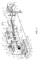
- FIG. 1 illustrates the winding device 1.
- the winding device 1 includes a spool 81, a bending mechanism 10, a feed mechanism 50, and a presser mechanism 70.
- the spool 81 is provided as a wire supply source.
- the bending mechanism 10 is provided as bending means for bending the rectangular wire 3 at a predetermined angle, for example, at 90 degrees in a direction within a horizontal plane while holding the rectangular wire 3 fed from the spool 81 in a horizontal direction between a main clamp 11 and a bender 12.
- the feed mechanism 50 is provided as feed means for feeding the rectangular wire 3 from the spool 81 by a preset length toward the bending mechanism 10.
- the presser mechanism 70 is provided between the feed mechanism 50 and the bending mechanism 10 as presser means for clamping the part of the rectangular wire 3 which is fed by the feed mechanism 50 toward the bending mechanism 10 so as to prevent the rectangular wire 3 from being drawn toward a downstream side by the bending operation of the bending mechanism 10.
- the feed mechanism 50 is configured to feed, to the bending mechanism 10, the rectangular wire 3 to have a predetermined length at a portion thereof corresponding to a size of each side of the edgewise coil 4 for each time.
- the winding device 1 for the edgewise coil further includes a correction unit 80.
- the correction unit 80 includes a vertical straightener portion 85 and a horizontal straightener portion 83.
- the vertical straightener portion 85 includes a plurality of guide rollers 84 arranged in a zigzag pattern to sandwich the rectangular wire 3 fed from the spool 81 therebetween in a thickness direction of the rectangular wire 3 to correct the rectangular wire 3 in the thickness direction.
- the horizontal straightener portion 83 includes a plurality of guide rollers 82 arranged in a zigzag pattern to sandwich the rectangular wire 3 fed from the spool 81 therebetween in a width direction of the rectangular wire 3 so as to correct the rectangular wire 3 in the width direction.
- the spool 81 is provided so as to be rotatable by an electric motor 86.
- a feeding detection unit 90 for detecting feeding of the rectangular wire 3 is provided between the spool 81 and the correction unit 80.
- the feeding detection unit 90 includes a pair of supporting columns 91 and 92, an upper-limit sensor 93, and a lower-limit sensor 94.
- the supporting columns 91 and 92 sandwich the part of the rectangular wire 3 fed from the spool 81 therebetween in the width direction.
- the upper-limit sensor 93 and the lower-limit sensor 94 are provided to the pair of supporting columns 91 and 92 to detect a deflection of the rectangular wire 3.
- the electric motor 86 rotates the spool 81 to feed the rectangular wire 3.
- the electric motor 86 stops the rotation of the spool 81 to stop the further feeding of the rectangular wire 3.
- the rectangular wire 3 is delivered from the spool 81 through the correction unit 80, the feed mechanism 50, and the presser mechanism 70 to the bending mechanism 10. Then, the rectangular wire 3 is wound into the edgewise coil 4 by the bending mechanism 10.
- a direction along the rectangular wire 3 from the spool 81 to the bending mechanism 10 is referred to as a Y-axis direction
- a direction within the plane at a right angle to the rectangular wire 3 is referred to as an X-axis direction
- a vertical direction orthogonal to the Y-axis direction and the X-axis direction is referred to as a Z-axis direction.
- the feed mechanism 50 includes a plurality of guides 55, a clamp 52, a driving mechanism 53, and a clamp actuation mechanism 54.
- the guides 55 are provided to a vertical plate 51 having a lower end fixed to a side surface of the table 2, and extend in the Y-axis direction.
- the clamp 52 is movable in a reciprocating manner along the guides 55 and comes into engagement with the rectangular wire 3 in the thickness direction when moving forward toward the bending mechanism 10.
- the driving mechanism 53 moves the clamp 52 in a reciprocating manner.
- the clamp actuation mechanism 54 is provided as clamp actuation means for actuating the clamp 52 so that the clamp 52 comes into engagement with the rectangular wire 3 when the clamp 52 is moved forward by the driving mechanism 53, and for disengaging the clamp 52 from the rectangular wire 3 when the clamp 52 is moved backward.
- the clamp 52 is configured to vertically sandwich the rectangular wire 3 and to be guided by the plurality of guides 55 so as to be movable in a reciprocating manner in the Y-axis direction.
- the clamp 52 includes a main body portion 56 having a cylindrical shape, and a base plate 57.
- the main body portion 56 moves in the reciprocating manner in the Y-axis direction along the guides 55.
- the base plate 57 is provided below the main body portion 56 and has an upper surface on which the rectangular wire 3 is placed.
- An engagement piece 58 is inserted into the main body portion 56 so as to be movable vertically.
- the engagement piece 58 includes an abutment piece 58a, a supporting piece 58b, a pressing piece 58d, and a guide bar 58e.
- the abutment piece 58a comes into direct contact with an upper surface of the rectangular wire 3 placed on the base plate 57.
- the supporting piece 58b is provided above the abutment piece 58a.
- the pressing piece 58d is provided above the supporting piece 58b through a spring 58c so as to be movable vertically.
- the guide bar 58e prevents misalignment of a center of the supporting piece 58b and a center of the pressing piece 58d from each other.
- a roller 61 is supported by the pressing piece 58d.
- the roller 61 is provided so as to partially project from an upper surface of the main body portion 56.
- Coil springs 59 for pushing up the engagement piece 58 are interposed between the abutment piece 58a and the base plate 57.
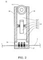
- FIG. 2 illustrates a state in which the engagement piece 58 is pushed up by the coil springs 59 to separate the engagement piece 58 away from the rectangular wire 3 and release the rectangular wire 3 from the clamp 52.
- the roller 61 is pushed down by the clamp actuation mechanism 54, the pressing piece 58d is moved down to bias the supporting piece 58b and the abutment piece 58a downward through the spring 58c.
- the rectangular wire 3 is compressed and held between the abutment piece 58a and the base plate 57. In this manner, the clamp 52 holds the rectangular wire 3.
- the clamp actuation mechanism 54 includes a vertically-movable plate 62, a clamp motor 64, and a spring (not shown).
- the vertically-movable plate 62 is provided to the vertical plate 51 so as to be movable upward and downward.
- the clamp motor 64 moves down the vertically-movable plate 62 by cam rollers 63.
- the spring biases upward the vertically-movable plate 62 so as to constantly hold the vertically-movable plate 62 in contact with the cam rollers 63.
- the vertically-movable plate 62 includes a rail 65 and rollers 66.
- the rail 65 is provided so as to extend in the Y-axis direction, and comes into engagement with the roller 61 ( FIG.
- the clamp actuation mechanism 54 moves down the vertically-movable plate 62 through the cam rollers 63 by the clamp motor 64 to push down the roller 61 ( FIG. 2 ) of the clamp 52 by the rail 65 so that the clamp 52 holds the rectangular wire 3.
- the clamp actuation mechanism 54 moves up the vertically-movable plate 62 through the cam rollers 63 by the clamp motor 64 to separate the rail 65 away from the roller 61 ( FIG. 2 ) of the clamp 52 and release the rectangular wire 3 held by the clamp 52 from the clamp 52.
- the driving mechanism 53 includes a ball screw 67 and a driving motor 68.
- the ball screw 67 is provided to the vertical plate 51 so as to extend in the Y-axis direction to be threadably fitted into the main body portion 56 of the clamp 52.
- the driving motor 68 rotationally drives the ball screw 67.
- the driving mechanism 53 moves backward the clamp 52 which has released the rectangular wire 3 to the initial position at the time of actuation of the presser mechanism 70 in association with the bending operation.
- the clamp 52 is actuated to move forward by the driving mechanism 53, the rectangular wire 3 is fed.
- the clamp 52 is actuated to move backward, only the clamp 52 moves backward.
- the clamp actuation mechanism 54 which moves up and down the vertically-movable plate 62 by the cam rollers 63 actuated by the clamp motor 64 has been described.
- the clamp actuation mechanism 54 described above is merely an example. Therefore, the vertically-movable plate 62 may be moved up and down by an air cylinder or the like. Further, the vertically-movable plate 62 may be moved up and down by other methods.
- the feed mechanism 50 may have any configuration as long as a preset length of the rectangular wire 3 can be fed from the spool 81 toward the bending mechanism 10.
- the feed mechanism 50 may drive a pair of rollers respectively held in contact with an upper surface and a lower surface of the rectangular wire 3 by a driving motor or the like to feed the rectangular wire 3.
- the presser mechanism 70 prevents the rectangular wire 3 from being drawn by a bending force when the rectangular wire 3 is bent by the bending mechanism 10.
- the presser mechanism 70 includes a frame body 71, a presser plate 72, a cam 73, and a motor 74.
- the frame body 71 is provided to the vertical plate 51 to support the rectangular wire 3 from below.
- the presser plate 72 is provided inside the frame body 71 so as to be movable upward and downward.
- the cam 73 moves down the presser plate 72.
- the motor 74 rotates the cam 73.
- the presser mechanism 70 uses the motor 74 to move down the presser plate 72 through the cam 73.
- the presser mechanism 70 compresses the rectangular wire 3 between the presser plate 72 and the frame body 71 to prevent the rectangular wire 3 from being drawn in the winding direction.
- the bending mechanism 10 is provided to a vertical plate 13 having a lower end fixed to the side surface of the table 2.
- a shelf plate 14 is provided to an upper part of the vertical plate 13 at a distance away from the table 2.
- the main clamp 11 and the bender 12 are retained by the shelf plate 14 in a suspended manner.
- the shelf plate 14 is provided with a cylindrical portion 14a projecting toward the table 2 provided below. Inside the cylindrical portion 14a, a cylindrical member 15 constituting the bender 12 is rotatably supported in a state in which axial movement of the cylindrical member 15 is restrained by two bearings 15a which are provided vertically.
- a cylindrical member 17 constituting the main clamp 11 is supported in a state in which axial movement of the cylindrical member 17 is restrained by two bearings 15b which are provided vertically.
- a columnar member 16 is inserted in a hollow portion of the cylindrical member 17, a columnar member 16 is inserted.
- the main clamp 11 includes the cylindrical member 17 and the columnar member 16 which is received inside the cylindrical member 17 so as to be movable axially as illustrated in FIGS. 3 and 4 .
- a lower end of the columnar member 16 is exposed from a lower end of the cylindrical member 17.
- a flange 18 for supporting the rectangular wire 3 from below is formed integrally with the lower end of the columnar member 16.
- a clearance for fixedly holding the upper surface and the lower surface of the rectangular wire 3 therein is formed by an upper surface of the flange 18 and a lower end surface of the cylindrical member 17.
- the main clamp 11 receives the rectangular wire 3 in the clearance between the upper surface of the flange 18 and the lower end surface of the cylindrical member 17 and uses the columnar member 16 exposed from the cylindrical member 17 as a fulcrum member at the time of bending.
- a radius of the columnar member 16 is formed so as to be equal to or slightly smaller than a curvature radius of an arc formed at a corner portion of a coil guide 31 described below.
- connection member 21 connects the columnar member 16 and the frame body 22 so as to allow the columnar member 16 and the frame body 22 to be integrally moved up and down.
- the rotation of the frame body 22 is blocked, and therefore the rotation of the columnar member 16 and the cylindrical member 17 is also blocked.
- the connection member 21, the frame body 22, the roller 23, the cam 25, and the main clamp motor 24 constitute a main-clamp actuation mechanism 20.
- the main-clamp motor 24 is rotated to move up the roller 23 by the cam 25 and move up the frame body 22. In this manner, the columnar member 16 is pulled up through the connection member 21. As a result, the rectangular wire 3 is sandwiched between the upper surface of the flange 18 and the lower end surface of the cylindrical member 17. A position at which the flange 18 is moved up is a clamp position.
- the rectangular wire 3 is vertically sandwiched to be pressed. As a result, the rectangular wire 3 can be prevented from bulging at the time of bending.
- a minimum size of the clearance between the upper surface of the flange 18 and the lower end surface of the cylindrical member 17 is determined by spacer plates 19 ( FIG. 4 ) which are provided to a lower end portion of the cylindrical member 17 so as to be inserted into the clearance.
- the main-clamp actuation mechanism 20 may have any configuration as long as the flange 18 can be moved up and down to the clamp position and the clamp release position.
- the columnar member 16 and the flange 18 may be moved up and down by an air cylinder or the like without using the above-mentioned cam mechanism (22 to 25). Further, the columnar member 16 and the flange 18 may be moved up and down by other methods.
- the bender 12 is fixed to a lower end of the cylindrical member 15.
- the bender 12 includes a vertical piece 12a and a pair of projecting pieces 12b.
- the vertical piece 12a is held in contact with a side surface of the rectangular wire 3 on the side opposite to the side of the rectangular wire 3 held by the main clamp 11.
- the projecting pieces 12b respectively project from an upper end and a lower end of the vertical piece 12a on an inner sufface toward the cylindrical member 17 and the flange 18.
- a concave portion for receiving one side surface of the rectangular wire 3 is formed between the pair of projecting pieces 12b.
- the upper and lower surfaces of the rectangular wire 3 are guided by the clearance between the upper surface of the flange 18 and the lower end surface of the cylindrical member 17, whereas a side surface of the rectangular wire 3 is guided by an outer circumference of the columnar member 16.
- a side surface and the upper and lower surfaces of the rectangular wire 3 are guided by the vertical piece 12a and the projecting pieces 12b of the bender 12.
- a receiving portion for the rectangular wire 3, which is configured to guide and bend the rectangular wire 3, is formed by the upper surface of the flange 18, the outer circumference of the columnar member 16, the lower end surface of the cylindrical member 17, and the vertical piece 12a and the projecting pieces 12b of the bender 12.
- a gear 27 is fixed to an upper end of the cylindrical member 15.
- a gear 29 fixed to an output shaft of a bending motor 28 fixed to the shelf plate 14 is brought into meshing engagement with the gear 27.
- the bending motor 28 rotates the cylindrical member 15 at 90 degrees from an initial position through an intermediation of the gears 27 and 29 which are in meshing engagement with each other to bend the rectangular wire 3 held in the receiving portion at 90 degrees, and then rotates the cylindrical member 15 at 90 degrees again to return the cylindrical member 15 to the initial position.
- the winding device 1 includes the coil guide 31 and a coil-guide moving mechanism 30.
- the edgewise coil 4 is formed by alternately repeating the feeding of the rectangular wire 3 by the feed mechanism 50 and the bending of the rectangular wire 3 by the bending mechanism 10, and therefore is lowered under its own weight.
- the coil guide 31 supports the edgewise coil 4 from below.
- the coil-guide moving mechanism 30 is provided as coil-guide moving means for moving the coil guide 31.
- the coil guide 31 includes a base plate 31b, a guide column 31c, and a guide base 31d.
- the base plate 31b is provided horizontally to an upper end of a supporting column 31a extending in a vertical direction.
- the guide column 31c is provided so as to stand vertically on the base plate 31b to be brought into engagement with an inner circumferential side of the first coil portion 4a having the rectangular cylindrical shape.
- the guide base 31d is provided so as to stand vertically on the base plate 31b and to be separated away from the guide column 31c.
- the guide column 31c is formed into a prismatic shape so as to have an outer circumferential shape approximately the same as an inner circumferential shape of the first coil portion 4a ( FIG. 7 ).
- each of four corner portions of the guide column 31c is formed to have an arc-like shape.
- the curvature radius of each of the corner portions is the same as the radius of the columnar member 16 of the bending mechanism 10.
- a height h of the guide column 31c is approximately equal to or slightly shorter than a length L ( FIG. 7 ) of the first coil portion 4a which is intended to be obtained.
- the guide base 31d is mounted on an upper surface of the base plate 31b through a leg member 31e so that an upper surface of the guide base 31d is located higher than the upper surface of the base plate 31b.
- the guide base 31d has an upper surface on which the second coil portion 4c ( FIG. 7 ) is to be placed.
- a height of a position of the upper surface of the guide base 31d from the upper surface of the base plate 31 b is formed to be at least equal to or slightly larger than the length of the first coil portion 4a.
- the coil-guide moving mechanism 30 follows the movement of the edgewise coil 4 by the feeding operation performed by the feed mechanism 50 to move the coil guide 31, and follows the edgewise coil 4 moving while rotating with the bending operation performed by the bending mechanism 50 to move the coil guide 31 while rotating the coil guide 31. Moreover, the coil-guide moving mechanism 30 moves up and down the coil guide 31.
- the coil-guide moving mechanism 30 includes a coil-guide rotating mechanism 32 ( FIG. 6 ), a coil-guide vertically-moving mechanism 36 ( FIG. 6 ), and an XY moving table 34.
- the coil-guide rotating mechanism 32 rotates the coil guide 31 about the Z axis.
- the coil-guide vertically-moving mechanism 36 moves up and down the coil guide 31 in the Z-axis direction.
- the XY moving table 34 moves the coil guide 31 in a direction within the horizontal plane.
- the coil-guide rotating mechanism 32 and the coil-guide vertically-moving mechanism 36 are provided to a coil-guide receiver 33.
- the XY moving table 34 is provided on the table 2 to support the coil-guide receiver 33, and changes a position of the coil-guide receiver 33 on the table 2.
- the coil-guide rotating mechanism 32 includes a large bevel gear 35.
- the large bevel gear 35 is provided in an upper part of the coil-guide receiver 33 and is rotatable about the Z axis by a bearing 33c.
- the supporting column 31a is spline-coupled to a center of the large bevel gear 35, and is provided so as to be unrotatable relative to the large bevel gear 35 and movable in the axial direction.
- the supporting column 31a extends downward through an axial portion of the large bevel gear 35 to reach inside of the coil-guide receiver 33.
- a vertically-moving block 37 is rotatably provided to a lower end of the supporting column 31a.
- An upper cylinder body 33b surrounding the supporting column 31a is provided to the coil-guide receiver 33.
- the vertically-moving block 37 is inserted together with the supporting column 31a into the upper cylinder body 33b so as to be movable vertically.
- An upper end of a ball screw 39 extending in the vertical direction is connected to the vertically-moving block 37.
- a ball nut 38 threadably fitted over the ball screw 39 is mounted to a lower part of the upper cylinder body 33b.
- the ball screw 39 is rotated by a servomotor 41.
- the servomotor 41 is received inside the lower cylinder body 33a so as to be movable vertically therein.
- the servomotor 41 rotationally drives the ball screw 39
- the vertically-moving block 37 provided to the upper end of the ball screw 39 is moved up and down because the ball nut 38 into which the ball screw 39 is threadably fitted cannot be moved up and down.
- the coil guide 31 is moved up and down through the supporting column 31a supported by the vertically-moving block 37.
- the vertically-moving block 37, the ball nut 38, the ball screw 39, and the servomotor 41 constitute a coil-guide vertically-moving mechanism 36 for moving up and down the coil guide 31.
- the coil-guide rotating mechanism 32 includes the large bevel gear 35, a coil-guide rotating motor 45, and a small bevel gear 46.
- the large bevel gear 35 is provided in the upper part of the coil-guide receiver 33.
- the coil-guide rotating motor 45 is provided on a side surface of the coil-guide receiver 33 so as to be rotatable about the Y axis (or the X axis).
- the small bevel gear 46 is rotated by the coil-guide rotating motor 45 so as to be brought into meshing engagement with the large bevel gear 35. Therefore, by rotating the small bevel gear 46 by the coil-guide rotating motor 45, the large bevel gear 35 is rotated about the Z axis. Then, the coil guide 31 is rotated about the Z axis through an intermediation of the supporting column 31a which rotates with the large bevel gear 35.
- the XY moving table 34 which changes the position of the coil-guide receiver 33 in the plane, includes a frame body 34a, a ball screw 47a, a Y-axis motor 47b, a Y-axis table 47d, a ball screw 48a, an X-axis motor 48b, and an X-axis table 48d as illustrated in FIG. 1 .
- the frame body 34a is fixed onto the table 2.
- the ball screw 47a passes through the frame body 34a to be arranged in the Y-axis direction.
- the Y-axis motor 47b rotationally drives the ball screw 47a.
- the Y-axis table 47d moves in the Y-axis direction along a Y-axis slider 47c by the rotation of the ball screw 47a.
- the ball screw 48a is provided above the Y-axis table 47d to be arranged in the X-axis direction.
- the X-axis motor 48b rotationally drives the ball screw 48a.
- the X-axis table 48d moves in the X-axis direction along an X-axis slider 48c by the rotation of the ball screw 48a.
- the coil-guide receiver 33 is fixed onto the X-axis table 48d.
- the coil guide 31 is configured so as to be movable in the three axis directions and rotatable by the coil-guide rotating mechanism 32, the coil-guide vertically-moving mechanism 36, and the XY moving table 34.
- the winding method for the edgewise coil 4 includes a first coil formation step of alternately repeating the feeding of the rectangular wire 3 from the spool 81 and the bending of the rectangular wire 3 to form the first coil portion 4a having the rectangular cylindrical shape, a connecting-wire formation step of forming the connecting wire 4b from a part of the rectangular wire 3 fed from the spool 81 after the formation of the first coil portion 4a, and a second coil formation step of sequentially bending a part of the rectangular wire 3 fed from the spool 81 after the formation of the connecting wire 4b in the same direction to form the second coil portion 4c having the rectangular cylindrical shape connected to the first coil portion 4a through the connecting wire 4b.
- a first coil formation step of alternately repeating the feeding of the rectangular wire 3 from the spool 81 and the bending of the rectangular wire 3 to form the first coil portion 4a having the rectangular cylindrical shape
- a connecting-wire formation step of forming the connecting wire 4b from a part of the rectangular wire 3 fed from the spool 81
- the feeding of the rectangular wire 3 from the spool 81 and the bending of the rectangular wire 3 are alternately repeated to form the first coil portion 4a having the rectangular cylindrical shape ( FIG. 7 ).
- a specific procedure is now described. As illustrated in FIG. 1 , the rectangular wire 3 is drawn from the spool 81 to pass through the vertical straightener 85 and the horizontal straightener 83, through the region between the main body portion 56 and the base plate 57 of the feed mechanism 50, and through the frame body 71 of the presser mechanism 70 to be guided to the bending mechanism 10.
- a direction of an opening of the receiving portion for the rectangular wire 3, which is formed by the upper surface of the flange 18 of the main clamp 11, the outer circumference of the columnar member 16, the lower end surface of the cylindrical member 17, and the vertical piece 12a and the projecting pieces 12b of the bender 12 is oriented in the Y-axis direction. Then, the flange 18 of the main clamp 11 is moved down to achieve the clamp release state in which the receiving portion for the rectangular wire 3 is opened.
- the clamp motor 64 of the feed mechanism 50 is rotated to bring convex portions of the cams 63 into abutment respectively with the rollers 66 of the vertically-movable plate 62 to move down the vertically-movable plate 62.
- the rail 65 comes into abutment with the roller 61 ( FIG. 2 ) of the clamp 52 to move down the roller 61.
- the rectangular wire 3 is clamped between the engagement piece 58 and the base plate 57.
- the ball screw 67 is rotationally driven by the driving motor 68 to move the clamp 52 including the main body portion 56 and the base plate 57 forward and feed the rectangular wire 3 by the predetermined length.
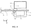
- the rectangular wire 3 is fed for the first time. By the first feeding, the rectangular wire 3 projects toward the distal end side beyond the receiving portion of the bending mechanism 10.
- the part of the fed rectangular wire 3 is bent.
- the motor 74 of the presser mechanism 70 illustrated in FIG. 1 is first actuated to move down the presser plate 72 and clamp the rectangular wire 3.
- the clamp motor 64 of the feed mechanism 50 is rotated to bring the concave portions of the cams 63 into abutment with the rollers 66 of the vertically-movable plate 62 and move up the vertically-movable plate 62.
- the rail 65 is separated away from the roller 61 of the clamp 52 to cancel a pressing force on the engagement piece 58 and release the clamping of the rectangular wire 3.
- the ball screw 67 is rotationally driven by the driving motor 68 to move the clamp 52 backward so that the clamp 52 returns to the initial position. While the clamp 52 is moving backward, the rectangular wire 3 maintains a stopped state. In this manner, preparation for next feeding is made.
- the sequentially formed first coil portion 4a is supported by the guide column 31c which comes into engagement with an inner circumference of the first coil portion 4a so as to move with the first coil portion 4a.
- the coil guide 31 is moved by the XY moving table 34, and is also rotated by the coil-guide rotating mechanism 32.
- the guide column 31c is located so that a side surface thereof comes into contact with the rectangular wire 3 projecting from the receiving portion within the XY plane (the rectangular wire 3 and the guide column 31c are separated away from each other in the Z-axis direction).
- the guide column 31 c is located so that the corner portion is separated away from the columnar member 16 by a predetermined distance A in the Y-axis direction.
- the predetermined distance A is determined based on a length size of the rectangular wire 3 (central portion of the rectangular wire 3) wound around the columnar member 16 (the arc-like corner portion of the coil guide 31). Therefore, the length size is set in accordance with a winding length over the surface of the columnar member 16 and a width size of the rectangular wire 3.
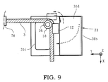
- the flange 18 of the main clamp 11 of the bending mechanism 10 is moved up to vertically narrow the receiving portion for the rectangular wire 3 and achieve the clamp state ( FIG. 3 ). Then, as indicated by the arrow in solid line illustrated in FIG. 9 , the bending motor 28 is rotated to rotate the cylindrical member 15 at 90 degrees and rotate the bender 12 about the columnar member 16 (main clamp 11 whose rotation is blocked) at 90 degrees, thereby bending the rectangular wire 3 at 90 degrees.
- the coil guide 31 is similarly rotated about the Z axis by the coil-guide rotating motor 45, while the center of the coil guide 31 is moved by the XY moving table 34 in the X and Y-axis directions with a trajectory (involute curve) on which the rectangular wire 3 is wound around the columnar member 16 at only 90 degrees.
- the coil guide 31 is moved while being rotated as indicated by the arrow in broken line illustrated in FIG. 9 so that the rectangular wire 3 to be bent along the side surface of the guide column 31c in the direction within the XY plane is moved so as to substantially keep the abutment state as viewed from above the XY plane.
- the rectangular wire 3 When the rectangular wire 3 is bent at 90 degrees, a tension to draw the rectangular wire 3 is applied to the rectangular wire 3 by a friction force between the bender 12 and the rectangular wire 3. However, the rectangular wire 3 is held by the presser mechanism 70. Therefore, the rectangular wire 3 is not drawn when the rectangular wire 3 is bent, and hence the coil shape does not become unstable. Moreover, when the rectangular wire 3 is bent at 90 degrees, the rectangular wire 3 contracts on the inner circumferential side of the bending. Therefore, without a large pressure thereon, the rectangular wire 3 bulges. The main-clamp actuation mechanism 20 is driven to move the main clamp 11 to the clamp position so that the pressing force is vertically applied to the rectangular wire 3 to prevent the rectangular wire 3 from bulging to be larger than a predetermined size.
- the main-clamp actuation mechanism 20 is actuated to move down the flange 18 of the main clamp 11 to vertically enlarge the receiving portion for the rectangular wire 3 so as to achieve the clamp release state.
- the cylindrical member 15 is reversely rotated at 90 degrees by the bending motor 28 to rotate the bender 12 about the columnar member 16 at 90 degrees and return the bender 12 to the original position. In this manner, the bending of the rectangular wire 3 is completed.
- the motor 74 of the presser mechanism 70 is actuated to move up the presser plate 72 and release the clamping for the rectangular wire 3.
- the clamp motor 64 of the feed mechanism 50 is rotated to bring the convex portions of the cams 63 into abutment with the rollers 66 and move down the vertically-movable plate 62.
- the rail 65 is brought into abutment with the roller 61 to move down the roller 61 and fixedly clamp the rectangular wire 3 between the engagement piece 58 and the base plate 57.
- the ball screw 67 is rotationally driven by the driving motor 68 to move the clamp 52 forward and feed the rectangular wire 3 by the predetermined length.
- the motor 74 of the presser mechanism 70 is actuated to move down the presser plate 72 and clamp the rectangular wire 3.
- the feed mechanism 50 is returned to the initial state under a state in which the rectangular wire 3 is released.
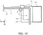
- the fed rectangular wire 3 projects toward the distal end side beyond the receiving portion by the predetermined length as indicated by the arrow in solid line as illustrated in FIG. 10 .
- the predetermined length is equal to the sum of a length of a straight portion of the first coil portion 4a of the edgewise coil 4 and a coil length (the above-mentioned predetermined distance A to be wound around the columnar member 16) at the time of bending at 90 degrees.
- the coil guide 31 also moves in the Y-axis direction as indicated by the arrow in broken line so as to keep a state in which the guide column 31c is substantially held in contact with the side surface of the rectangular wire 3.
- the rectangular wire 3 is bent again.
- the newly fed rectangular wire 3 is vertically compressed by bringing the main clamp 11 into the clamp state by the main-clamp actuation mechanism 20 to rotate the bender 12 about the columnar member 16 as indicated by the arrow in solid line and bend the rectangular wire 3 as illustrated in FIG. 11 .
- the coil-guide moving mechanism 30 rotates the coil guide 31 about the Z axis and moves the coil guide 31 in the X-axis and Y-axis directions.
- the coil guide 31 is moved while being rotated as indicated by the arrow in broken line illustrated in FIG. 11 so as to keep a state in which the rectangular wire 3 is substantially held in abutment with the side surface of the guide column 31c within the XY plane.
- the main-clamp actuation mechanism 20 is actuated to move down the flange 18 of the main clamp 11 to vertically enlarge the receiving portion for the rectangular wire 3 and achieve the clamp release state.
- the cylindrical member 15 is reversely rotated by the bending motor 28 at 90 degrees as indicated by the arrow in alternate long and short dash line illustrated in FIG. 11 to rotate the bender 12 about the columnar member 16 at 90 degrees and return the bender 12 to the original position. In this manner, the second bending operation is terminated.
- each of the feeding and the bending of the rectangular wire 3 is required to be repeated four times.
- each of the feeding and the bending of the rectangular wire 3 is repeated twice.
- long side and short side of the first coil portion 4a are formed as illustrated in FIG. 11 . Therefore, in order to obtain the first coil portion 4a having a square shape, the feeding and bending of the rectangular wire 3 are required to be repeated another two times after the state illustrated in FIG. 11 .
- the feeding of the rectangular wire 3 to form another long side of the first coil portion 4a is further performed as illustrated in FIG. 12 .
- the part of the fed rectangular wire 3 is bent as illustrated in FIG. 13 .
- the long side of the first coil portion 4a is formed.
- the feeding of the rectangular wire 3 to form another short side of the first coil portion 4a is further performed.
- the bending is further performed. By repeating the feeding and bending four times, the first coil portion 4a formed by one turn of the rectangular wire 3 is formed.
- the first coil portion 4a made of the rectangular wire 3 wound a plurality of times is sequentially formed. As illustrated in FIG. 16 , the sequentially formed first coil portion 4a is lowered under its own weight to move down around the guide column 31c of the coil guide 31 moving with the feeding and bending of the rectangular wire 3 so that the inner circumference is supported by the guide column 31c.
- the guide column 31c moves following the movement and rotation of the first coil portion 4a to restrain oscillation of the first coil portion 4a.
- the first coil portion 4a obtained by winding is prevented from being moved in the axial direction (vertical direction) and the radial direction (outer circumferential direction) to excessively oscillate.
- the first coil formation step is terminated.
- the rectangular wire 3 is fed again from the spool 81 to form the connecting wire 4b.
- the feeding of the rectangular wire 3 is the same as the feeding of the rectangular wire 3 in the first coil formation step.
- the clamp motor 64 is rotated to fixedly clamp the rectangular wire 3 between the engagement piece 58 and the base plate 57.
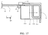
- the ball screw 67 is rotationally driven by the driving motor 68 to move the clamp 52 forward and feed the rectangular wire 3 by the predetermined length as indicated by the arrow in solid line illustrated in FIG. 17 .
- the part of the fed rectangular wire 3 has a length equal to a required length of the connecting wire 4b.
- the coil guide 31 In synchronization with the feed of the rectangular wire 3, the coil guide 31 also moves as indicated by the arrow in alternate long and short dash line. With the thus fed rectangular wire 3, the first coil portion 4a supported by the guide column 31c also moves in the same direction. Then, for the subsequent second coil formation step, the guide base 31d of the coil guide 31 is located at a position below the columnar member 16, which corresponds to a new bending position.
- the rectangular wire 3 fed from the spool 81 is sequentially bent in the same direction to form the second coil portion 4c having the rectangular cylindrical shape, which is connected to the first coil portion 4a through the connecting wire 4b.
- the feeding and bending operation of the rectangular wire 3 is the same as that of the rectangular wire 3 in the first coil formation step.
- a first short side of the second coil portion 4c is formed by first bending of the rectangular wire 3.
- a first long side of the second coil portion 4c is formed.
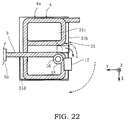
- a second short side of the second coil portion 4c is formed by feeding of the rectangular wire 3 illustrated in FIG. 21 and bending of the rectangular wire 3 illustrated in FIG. 22 .
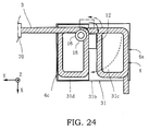
- a second long side of the second coil portion 4c is formed by feeding of the rectangular wire 3 illustrated in FIG. 23 and bending of the rectangular wire 3 illustrated in FIG. 24 .
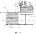
- the sequentially formed second coil portion 4c is placed on the guide base 31d which is provided adjacent to the guide column 31c and moves together with the guide column 31c so that the guide base 31d moves together with the second coil portion 4c.
- the second coil portion 4c obtained by repeating the feeding and bending of the rectangular wire 3 is lowered under its own weight to be placed on the guide base 31d.
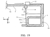
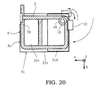
- the guide base 31d moves following the movement and rotation of the second coil portion 4c as indicated by the arrows in broken lines illustrated in FIGS. 18 to 24 .
- the second coil portion 4c is restrained from oscillating.
- the guide base 31d on which the second coil portion 4c is placed, is sequentially moved down in accordance with the formation of the second coil portion 4c.
- the guide base 31d is moved down by driving the servomotor 41 to rotate the ball screw 39 so as to move down the vertically-moving block 37 provided with the ball screw 39 and move down the coil guide 31 through the supporting column 31a supported by the vertically-moving block 37.
- the guide base 31d It is preferred to move down the guide base 31d by the amount equal to a thickness of the rectangular wire 3 each time one turn is formed by bending the rectangular wire 3 four times. In this manner, even when the rectangular wire 3 is wound at a high speed, the wound second coil portion 4c as well as the first coil portion 4a is prevented from moving in the axial direction (vertical direction) and the radial direction (outer circumferential direction) with respect to the coil guide 31 to excessively oscillate. Then, at a time at which the second coil portion 4c having the rectangular cylindrical shape formed by a predetermined number of turns of the rectangular wire 3 is obtained, the second coil formation step is terminated.
- the edgewise coil 4 obtained by the winding method according to this embodiment includes the first coil portion 4a having the rectangular cylindrical shape and the second coil portion 4c having the rectangular cylindrical shape connected to the first coil portion 4a through the connecting wire 4b, and has a stepwise shape with the position of the center axis of the first coil portion 4a and that of the center axis of the second coil portion 4c being shifted from each other.
- the edgewise coil 4 in which the first coil portion 4a and the second coil portion 4c each having the rectangular cylindrical shape with the center axes being shifted from each other are continuously formed through the connecting wire 4b, can be obtained by edgewise winding of the single rectangular wire 3. Therefore, with the winding device 1 according to this embodiment, neither the size of the winding device 1 nor the area for installation of the winding device 1 is increased.
- a winding device includes a bending mechanism for bending a rectangular wire, a feed mechanism for feeding the rectangular wire, a coil guide for supporting an edgewise coil formed by alternately repeating the feeding of the rectangular wire by the feed mechanism and the bending of the rectangular wire by the bending mechanism, and a coil-guide moving mechanism for moving the coil guide while rotating the coil guide.
- the coil guide includes a guide column to be brought into engagement with an inner circumference of a first coil portion having a cylindrical shape, and a guide base on which a second coil portion is to be placed, the second coil portion having a cylindrical shape connected to the first coil portion through a connecting wire and having a center axis that is shifted in position from a center axis of the first coil portion to form a stepwise shape.
Landscapes
- Engineering & Computer Science (AREA)
- Power Engineering (AREA)
- Manufacturing & Machinery (AREA)
- Manufacture Of Motors, Generators (AREA)
- Coil Winding Methods And Apparatuses (AREA)
- Formation Of Various Coating Films On Cathode Ray Tubes And Lamps (AREA)
Description
- The present invention relates to a winding device and a winding method for an edgewise coil.
- In order to improve efficiency of utilization of a space for winding when a coated copper wire is wound in a coil-like shape, there has conventionally been proposed a winding device for an edgewise coil, which is configured so that a rectangular wire having a rectangular cross section is sequentially bent so as to be vertically wound (the rectangular wire is wound in a width direction) to form an edgewise coil (see
JP-A-2009-302245 - For actual use of the edgewise coil described above, two edgewise coils are formed in parallel, and the two parallel edgewise coils are connected. Therefore, conventionally, two edgewise coils are respectively formed with separate windings. Then, ends of the windings, which are to be connected, are welded together through a communication terminal. In recent years, however, two edgewise coils arranged in parallel are required to be formed by edgewise winding of a single rectangular wire.
- As a device for the above-mentioned formation of the two edgewise coils, the following linked coil formation device has been proposed. Specifically, the linked coil formation device includes a first coil winding processing line having a first winding head for sequentially winding one end part of a coil material made of a rectangular wire into a rectangular shape to form a first coil part into a shape of a rectangular cylinder, a second coil winding processing line having a second winding head for forming a second coil part into the shape of the rectangular cylinder at the other end part of the coil material and for arranging the second coil part to be adjacent to the first coil part on an identical face, and a material transfer unit for conveying the coil material having the first coil part formed in the first coil winding processing line into the second coil winding processing line on an extension of each of the first and second coil winding processing lines at an opposite side of the material feed area (see
WO2009/107633A ). - However, in the conventional linked coil formation device, the two winding processing lines, each being capable of individually forming the edgewise coil, are connected by the material transfer unit. Specifically, the linked coil formation device described above has a structure in which the two independent edgewise coil formation devices are connected. Therefore, the size of the linked coil formation device is remarkably increased. Thus, in order to install the linked coil formation device, an area equal to or larger than an area, on which at least two independent edgewise coil formation devices can be installed, is required.
-
US 2010/319802 A1 shows a linked coil formation device and a method of forming linked coils. Accordingly, a first coil winding processing line having a first winding head forming a first coil part in the shape of a rectangular cylinder at one end part of a flat wire, a second coil winding processing line disposed in parallel to the first coil winding processing line and having a second winding head on which a second coil part in the shape of a rectangular cylinder is formed at the other end part of the flat wire and both of the coil parts are arranged to be adjacent to each other on an identical face, and a coil placement unit for conveying the flat wire W having the first coil part from the first coil winding processing line to the second coil winding processing line along each coil winding processing line are provided for forming such linked coils. - It is an object of the present invention to provide a winding device and a winding method for an edgewise coil, which are capable of continuously forming a first coil portion having a cylindrical shape and a second coil portion having a cylindrical shape connected to the first coil portion through a connecting wire to obtain such an edgewise coil that a position of a center axis of the first coil portion and that of a center axis of the second coil portion are shifted from each other to form a stepwise shape.
- The object of the present invention is achieved by a winding device for an edgewise coil having the features of
claim 1 and by a winding method for an edgewise coil having the features ofclaim 3. - Further advantageous developments of the present invention are defined in the dependent claims.
- In the accompanying drawings:
-
FIG. 1 a perspective view illustrating a schematic configuration of a winding device according to an embodiment of the present invention; -
FIG. 2 is a schematic sectional view of a clamp; -
FIG. 3 is a sectional configuration view of a bending mechanism; -
FIG. 4 is a perspective view of a main clamp; -
FIG. 5 is a perspective view of a coil guide; -
FIG. 6 is a sectional configuration view of a coil-guide moving mechanism; -
FIG. 7 is a perspective view of an edgewise coil obtained by the winding device according to the embodiment of the present invention; -
FIG. 8 is an operation diagram illustrating first feeding of a rectangular wire for formation of a first coil portion; -
FIG. 9 is an operation diagram illustrating bending of the rectangular wire; -
FIG. 10 is an operation diagram illustrating feeding of the rectangular wire, which is subsequent toFIG. 9 ; -
FIG. 11 is an operation diagram illustrating bending of the rectangular wire, which is subsequent toFIG. 10 ; -
FIG. 12 is an operation diagram illustrating feeding of the rectangular wire, which is subsequent toFIG. 11 ; -
FIG. 13 is an operation diagram illustrating bending of the rectangular wire, which is subsequent toFIG. 12 ; -
FIG. 14 is an operation diagram illustrating feeding of the rectangular wire, which is subsequent toFIG. 13 ; -
FIG. 15 is an operation diagram illustrating bending of the rectangular wire, which is subsequent toFIG. 14 ; -
FIG. 16 is a diagram illustrating a state in which the first coil portion formed around a guide column is lowered along the guide column; -
FIG. 17 is an operation diagram illustrating a state in which the rectangular wire is fed to form a connecting wire; -
FIG. 18 is an operation diagram illustrating first bending of the rectangular wire for formation of a second coil portion; -
FIG. 19 is an operation diagram illustrating feeding of the rectangular wire, which is subsequent toFIG. 18 ; -
FIG. 20 is an operation diagram illustrating bending of the rectangular wire, which is subsequent toFIG. 19 ; -
FIG. 21 is an operation diagram illustrating feeding of the rectangular wire, which is subsequent toFIG. 20 ; -
FIG. 22 is an operation diagram illustrating bending of the rectangular wire, which is subsequent toFIG. 21 ; -
FIG. 23 is an operation diagram illustrating feeding of the rectangular wire, which is subsequent toFIG. 22 ; -
FIG. 24 is an operation diagram illustrating bending of the rectangular wire, which is subsequent toFIG. 23 ; and -
FIG. 25 is a diagram illustrating a state in which the formed second coil portion is supported on a guide base. - In the following, an embodiment of the present invention is described referring to the accompanying drawings.
-
FIG. 7 illustrates an edgewise coil 4 (hereinafter also referred to simply as "coil 4") obtained by awinding device 1 for an edgewise coil according to the embodiment of the present invention. Theedgewise coil 4 includes afirst coil portion 4a having a rectangular cylindrical shape and asecond coil portion 4c having a rectangular cylindrical shape, which is connected to thefirst coil portion 4a through a connectingwire 4b. A position of a center axis of thefirst coil portion 4a and that of a center axis of thesecond coil portion 4c are shifted from each other, and hence theedgewise coil 4a is formed into a stepwise shape. Thefirst coil portion 4a and thesecond coil portion 4c are obtained by alternately repeating feeding of arectangular wire 3 as a wire and bending of therectangular wire 3 in a width direction.FIG. 7 illustrates theedgewise coil 4 formed in the following manner. Specifically, therectangular wire 3 is bent at 90 degrees for each time, and the feeding and the bending in the same direction are repeated four times for therectangular wire 3 to form one turn of therectangular wire 3. -
FIG. 1 illustrates thewinding device 1. Thewinding device 1 includes aspool 81, abending mechanism 10, afeed mechanism 50, and apresser mechanism 70. Thespool 81 is provided as a wire supply source. Thebending mechanism 10 is provided as bending means for bending therectangular wire 3 at a predetermined angle, for example, at 90 degrees in a direction within a horizontal plane while holding therectangular wire 3 fed from thespool 81 in a horizontal direction between amain clamp 11 and abender 12. Thefeed mechanism 50 is provided as feed means for feeding therectangular wire 3 from thespool 81 by a preset length toward thebending mechanism 10. Thepresser mechanism 70 is provided between thefeed mechanism 50 and thebending mechanism 10 as presser means for clamping the part of therectangular wire 3 which is fed by thefeed mechanism 50 toward thebending mechanism 10 so as to prevent therectangular wire 3 from being drawn toward a downstream side by the bending operation of thebending mechanism 10. Corresponding to a winding operation performed by thebending mechanism 10, thefeed mechanism 50 is configured to feed, to thebending mechanism 10, therectangular wire 3 to have a predetermined length at a portion thereof corresponding to a size of each side of theedgewise coil 4 for each time. - The winding
device 1 for the edgewise coil further includes acorrection unit 80. Thecorrection unit 80 includes avertical straightener portion 85 and ahorizontal straightener portion 83. Thevertical straightener portion 85 includes a plurality ofguide rollers 84 arranged in a zigzag pattern to sandwich therectangular wire 3 fed from thespool 81 therebetween in a thickness direction of therectangular wire 3 to correct therectangular wire 3 in the thickness direction. Thehorizontal straightener portion 83 includes a plurality ofguide rollers 82 arranged in a zigzag pattern to sandwich therectangular wire 3 fed from thespool 81 therebetween in a width direction of therectangular wire 3 so as to correct therectangular wire 3 in the width direction. - The
spool 81 is provided so as to be rotatable by anelectric motor 86. A feedingdetection unit 90 for detecting feeding of therectangular wire 3 is provided between thespool 81 and thecorrection unit 80. The feedingdetection unit 90 includes a pair of supportingcolumns limit sensor 93, and a lower-limit sensor 94. The supportingcolumns rectangular wire 3 fed from thespool 81 therebetween in the width direction. The upper-limit sensor 93 and the lower-limit sensor 94 are provided to the pair of supportingcolumns rectangular wire 3. When the upper-limit sensor 93 detects a reduction in the amount of deflection of therectangular wire 3, theelectric motor 86 rotates thespool 81 to feed therectangular wire 3. When the lower-limit sensor 94 detects an increase in the amount of deflection of therectangular wire 3, theelectric motor 86 stops the rotation of thespool 81 to stop the further feeding of therectangular wire 3. Thebending mechanism 10, thefeed mechanism 50, thepresser mechanism 70, and thecorrection unit 80 are mounted to a table 2 serving as a base, whereas thefeeding detection unit 90 is provided adjacent to the table 2. - The
rectangular wire 3 is delivered from thespool 81 through thecorrection unit 80, thefeed mechanism 50, and thepresser mechanism 70 to thebending mechanism 10. Then, therectangular wire 3 is wound into theedgewise coil 4 by thebending mechanism 10. In the following, for description, a direction along therectangular wire 3 from thespool 81 to thebending mechanism 10 is referred to as a Y-axis direction, a direction within the plane at a right angle to therectangular wire 3 is referred to as an X-axis direction, and a vertical direction orthogonal to the Y-axis direction and the X-axis direction is referred to as a Z-axis direction. - The
feed mechanism 50 includes a plurality ofguides 55, aclamp 52, a driving mechanism 53, and aclamp actuation mechanism 54. Theguides 55 are provided to avertical plate 51 having a lower end fixed to a side surface of the table 2, and extend in the Y-axis direction. Theclamp 52 is movable in a reciprocating manner along theguides 55 and comes into engagement with therectangular wire 3 in the thickness direction when moving forward toward thebending mechanism 10. The driving mechanism 53 moves theclamp 52 in a reciprocating manner. Theclamp actuation mechanism 54 is provided as clamp actuation means for actuating theclamp 52 so that theclamp 52 comes into engagement with therectangular wire 3 when theclamp 52 is moved forward by the driving mechanism 53, and for disengaging theclamp 52 from therectangular wire 3 when theclamp 52 is moved backward. - The
clamp 52 is configured to vertically sandwich therectangular wire 3 and to be guided by the plurality ofguides 55 so as to be movable in a reciprocating manner in the Y-axis direction. As illustrated inFIG. 2 , theclamp 52 includes amain body portion 56 having a cylindrical shape, and abase plate 57. Themain body portion 56 moves in the reciprocating manner in the Y-axis direction along theguides 55. Thebase plate 57 is provided below themain body portion 56 and has an upper surface on which therectangular wire 3 is placed. Anengagement piece 58 is inserted into themain body portion 56 so as to be movable vertically. Theengagement piece 58 includes anabutment piece 58a, a supportingpiece 58b, apressing piece 58d, and aguide bar 58e. Theabutment piece 58a comes into direct contact with an upper surface of therectangular wire 3 placed on thebase plate 57. The supportingpiece 58b is provided above theabutment piece 58a. Thepressing piece 58d is provided above the supportingpiece 58b through aspring 58c so as to be movable vertically. Theguide bar 58e prevents misalignment of a center of the supportingpiece 58b and a center of thepressing piece 58d from each other. Aroller 61 is supported by thepressing piece 58d. Theroller 61 is provided so as to partially project from an upper surface of themain body portion 56. Coil springs 59 for pushing up theengagement piece 58 are interposed between theabutment piece 58a and thebase plate 57.FIG. 2 illustrates a state in which theengagement piece 58 is pushed up by the coil springs 59 to separate theengagement piece 58 away from therectangular wire 3 and release therectangular wire 3 from theclamp 52. When theroller 61 is pushed down by theclamp actuation mechanism 54, thepressing piece 58d is moved down to bias the supportingpiece 58b and theabutment piece 58a downward through thespring 58c. As a result, therectangular wire 3 is compressed and held between theabutment piece 58a and thebase plate 57. In this manner, theclamp 52 holds therectangular wire 3. - As illustrated in
FIG. 1 , theclamp actuation mechanism 54 includes a vertically-movable plate 62, aclamp motor 64, and a spring (not shown). The vertically-movable plate 62 is provided to thevertical plate 51 so as to be movable upward and downward. Theclamp motor 64 moves down the vertically-movable plate 62 bycam rollers 63. The spring biases upward the vertically-movable plate 62 so as to constantly hold the vertically-movable plate 62 in contact with thecam rollers 63. The vertically-movable plate 62 includes arail 65 androllers 66. Therail 65 is provided so as to extend in the Y-axis direction, and comes into engagement with the roller 61 (FIG. 2 ) of theclamp 52 to push down theroller 61 when the vertically-movable plate 62 is moved down. Therollers 66 are provided so as to be held in contact with thecam rollers 63. When theclamp 52 is moved forward, theclamp actuation mechanism 54 moves down the vertically-movable plate 62 through thecam rollers 63 by theclamp motor 64 to push down the roller 61 (FIG. 2 ) of theclamp 52 by therail 65 so that theclamp 52 holds therectangular wire 3. On the other hand, when theclamp 52 is moved backward, theclamp actuation mechanism 54 moves up the vertically-movable plate 62 through thecam rollers 63 by theclamp motor 64 to separate therail 65 away from the roller 61 (FIG. 2 ) of theclamp 52 and release therectangular wire 3 held by theclamp 52 from theclamp 52. - The driving mechanism 53 includes a
ball screw 67 and a drivingmotor 68. The ball screw 67 is provided to thevertical plate 51 so as to extend in the Y-axis direction to be threadably fitted into themain body portion 56 of theclamp 52. The drivingmotor 68 rotationally drives theball screw 67. When therectangular wire 3 is to be delivered, the driving mechanism 53 moves forward theclamp 52 holding therectangular wire 3 by a predetermined length corresponding to a size of each side of theedgewise coil 4 from an initial position toward thebending mechanism 10 by theball screw 67. On the other hand, when a bending operation is to be performed by thebending mechanism 10, the driving mechanism 53 moves backward theclamp 52 which has released therectangular wire 3 to the initial position at the time of actuation of thepresser mechanism 70 in association with the bending operation. As described above, when theclamp 52 is actuated to move forward by the driving mechanism 53, therectangular wire 3 is fed. On the other hand, when theclamp 52 is actuated to move backward, only theclamp 52 moves backward. - The
clamp actuation mechanism 54 which moves up and down the vertically-movable plate 62 by thecam rollers 63 actuated by theclamp motor 64 has been described. However, theclamp actuation mechanism 54 described above is merely an example. Therefore, the vertically-movable plate 62 may be moved up and down by an air cylinder or the like. Further, the vertically-movable plate 62 may be moved up and down by other methods. Thefeed mechanism 50 may have any configuration as long as a preset length of therectangular wire 3 can be fed from thespool 81 toward thebending mechanism 10. For example, thefeed mechanism 50 may drive a pair of rollers respectively held in contact with an upper surface and a lower surface of therectangular wire 3 by a driving motor or the like to feed therectangular wire 3. - The
presser mechanism 70 prevents therectangular wire 3 from being drawn by a bending force when therectangular wire 3 is bent by thebending mechanism 10. Thepresser mechanism 70 includes a frame body 71, a presser plate 72, acam 73, and amotor 74. The frame body 71 is provided to thevertical plate 51 to support therectangular wire 3 from below. The presser plate 72 is provided inside the frame body 71 so as to be movable upward and downward. Thecam 73 moves down the presser plate 72. Themotor 74 rotates thecam 73. When therectangular wire 73 is bent at 90 degrees by thebending mechanism 10, a large tensile force acts in a winding direction of therectangular wire 3. If therectangular wire 3 is drawn in the winding direction by the tensile force, lengths of the respective sides of theedgewise coil 4 are varied to deform a coil shape. When therectangular wire 3 is to be bent at 90 degrees by thebending mechanism 10, thepresser mechanism 70 uses themotor 74 to move down the presser plate 72 through thecam 73. Thus, thepresser mechanism 70 compresses therectangular wire 3 between the presser plate 72 and the frame body 71 to prevent therectangular wire 3 from being drawn in the winding direction. - The
bending mechanism 10 is provided to avertical plate 13 having a lower end fixed to the side surface of the table 2. Ashelf plate 14 is provided to an upper part of thevertical plate 13 at a distance away from the table 2. Themain clamp 11 and thebender 12 are retained by theshelf plate 14 in a suspended manner. As illustrated inFIG. 3 , theshelf plate 14 is provided with acylindrical portion 14a projecting toward the table 2 provided below. Inside thecylindrical portion 14a, acylindrical member 15 constituting thebender 12 is rotatably supported in a state in which axial movement of thecylindrical member 15 is restrained by twobearings 15a which are provided vertically. Inside thecylindrical member 15, acylindrical member 17 constituting themain clamp 11 is supported in a state in which axial movement of thecylindrical member 17 is restrained by twobearings 15b which are provided vertically. In a hollow portion of thecylindrical member 17, acolumnar member 16 is inserted. - The
main clamp 11 includes thecylindrical member 17 and thecolumnar member 16 which is received inside thecylindrical member 17 so as to be movable axially as illustrated inFIGS. 3 and4 . A lower end of thecolumnar member 16 is exposed from a lower end of thecylindrical member 17. Aflange 18 for supporting therectangular wire 3 from below is formed integrally with the lower end of thecolumnar member 16. A clearance for fixedly holding the upper surface and the lower surface of therectangular wire 3 therein is formed by an upper surface of theflange 18 and a lower end surface of thecylindrical member 17. Themain clamp 11 receives therectangular wire 3 in the clearance between the upper surface of theflange 18 and the lower end surface of thecylindrical member 17 and uses thecolumnar member 16 exposed from thecylindrical member 17 as a fulcrum member at the time of bending. A radius of thecolumnar member 16 is formed so as to be equal to or slightly smaller than a curvature radius of an arc formed at a corner portion of acoil guide 31 described below. - As illustrated in
FIG. 3 , an upper end of thecolumnar member 16 is connected to aframe body 22 which is movable upward and downward through aconnection member 21 as connection means. Aroller 23 is rotatably supported by theframe body 22. Acam 25 comes into engagement with theroller 23. Thecam 25 is rotationally driven by a main-clamp motor 24 fixed to theshelf plate 14. Theconnection member 21 connects thecolumnar member 16 and theframe body 22 so as to allow thecolumnar member 16 and theframe body 22 to be integrally moved up and down. The rotation of theframe body 22 is blocked, and therefore the rotation of thecolumnar member 16 and thecylindrical member 17 is also blocked. Theconnection member 21, theframe body 22, theroller 23, thecam 25, and themain clamp motor 24 constitute a main-clamp actuation mechanism 20. - When the
rectangular wire 3 is to be bent, the main-clamp motor 24 is rotated to move up theroller 23 by thecam 25 and move up theframe body 22. In this manner, thecolumnar member 16 is pulled up through theconnection member 21. As a result, therectangular wire 3 is sandwiched between the upper surface of theflange 18 and the lower end surface of thecylindrical member 17. A position at which theflange 18 is moved up is a clamp position. When therectangular wire 3 is to be bent, therectangular wire 3 is vertically sandwiched to be pressed. As a result, therectangular wire 3 can be prevented from bulging at the time of bending. A minimum size of the clearance between the upper surface of theflange 18 and the lower end surface of thecylindrical member 17 is determined by spacer plates 19 (FIG. 4 ) which are provided to a lower end portion of thecylindrical member 17 so as to be inserted into the clearance. - When the main-
clamp motor 24 is rotated to move down theroller 23 by thecam 25, theframe body 22 is moved down and thecolumnar member 16 is moved down through theconnection member 21. As a result, the distance between the upper surface of theflange 18 and the lower end surface of thecylindrical member 17 is increased to release therectangular wire 3 from themain clamp 11. A position at which theflange 18 is moved down is a clamp release position. - The above-mentioned configuration of the main-
clamp actuation mechanism 20 is merely an example. Therefore, the main-clamp actuation mechanism 20 may have any configuration as long as theflange 18 can be moved up and down to the clamp position and the clamp release position. For example, thecolumnar member 16 and theflange 18 may be moved up and down by an air cylinder or the like without using the above-mentioned cam mechanism (22 to 25). Further, thecolumnar member 16 and theflange 18 may be moved up and down by other methods. - The
bender 12 is fixed to a lower end of thecylindrical member 15. Thebender 12 includes avertical piece 12a and a pair of projectingpieces 12b. Thevertical piece 12a is held in contact with a side surface of therectangular wire 3 on the side opposite to the side of therectangular wire 3 held by themain clamp 11. The projectingpieces 12b respectively project from an upper end and a lower end of thevertical piece 12a on an inner sufface toward thecylindrical member 17 and theflange 18. A concave portion for receiving one side surface of therectangular wire 3 is formed between the pair of projectingpieces 12b. - On the
main clamp 11 side, the upper and lower surfaces of therectangular wire 3 are guided by the clearance between the upper surface of theflange 18 and the lower end surface of thecylindrical member 17, whereas a side surface of therectangular wire 3 is guided by an outer circumference of thecolumnar member 16. On thebender 12 side, a side surface and the upper and lower surfaces of therectangular wire 3 are guided by thevertical piece 12a and the projectingpieces 12b of thebender 12. In this manner, a receiving portion for therectangular wire 3, which is configured to guide and bend therectangular wire 3, is formed by the upper surface of theflange 18, the outer circumference of thecolumnar member 16, the lower end surface of thecylindrical member 17, and thevertical piece 12a and the projectingpieces 12b of thebender 12. - A
gear 27 is fixed to an upper end of thecylindrical member 15. Agear 29 fixed to an output shaft of a bendingmotor 28 fixed to theshelf plate 14 is brought into meshing engagement with thegear 27. The bendingmotor 28 rotates thecylindrical member 15 at 90 degrees from an initial position through an intermediation of thegears rectangular wire 3 held in the receiving portion at 90 degrees, and then rotates thecylindrical member 15 at 90 degrees again to return thecylindrical member 15 to the initial position. - As illustrated in
FIG. 1 , the windingdevice 1 includes thecoil guide 31 and a coil-guide moving mechanism 30. Theedgewise coil 4 is formed by alternately repeating the feeding of therectangular wire 3 by thefeed mechanism 50 and the bending of therectangular wire 3 by thebending mechanism 10, and therefore is lowered under its own weight. Thecoil guide 31 supports theedgewise coil 4 from below. The coil-guide moving mechanism 30 is provided as coil-guide moving means for moving thecoil guide 31. - As illustrated in
FIG. 5 , thecoil guide 31 includes abase plate 31b, aguide column 31c, and aguide base 31d. Thebase plate 31b is provided horizontally to an upper end of a supportingcolumn 31a extending in a vertical direction. Theguide column 31c is provided so as to stand vertically on thebase plate 31b to be brought into engagement with an inner circumferential side of thefirst coil portion 4a having the rectangular cylindrical shape. Theguide base 31d is provided so as to stand vertically on thebase plate 31b and to be separated away from theguide column 31c. Theguide column 31c is formed into a prismatic shape so as to have an outer circumferential shape approximately the same as an inner circumferential shape of thefirst coil portion 4a (FIG. 7 ). Thus, each of four corner portions of theguide column 31c is formed to have an arc-like shape. The curvature radius of each of the corner portions is the same as the radius of thecolumnar member 16 of thebending mechanism 10. A height h of theguide column 31c is approximately equal to or slightly shorter than a length L (FIG. 7 ) of thefirst coil portion 4a which is intended to be obtained. - The
guide base 31d is mounted on an upper surface of thebase plate 31b through aleg member 31e so that an upper surface of theguide base 31d is located higher than the upper surface of thebase plate 31b. Theguide base 31d has an upper surface on which thesecond coil portion 4c (FIG. 7 ) is to be placed. A height of a position of the upper surface of theguide base 31d from the upper surface of thebase plate 31 b is formed to be at least equal to or slightly larger than the length of thefirst coil portion 4a. - As illustrated in
FIG. 1 , the coil-guide moving mechanism 30 follows the movement of theedgewise coil 4 by the feeding operation performed by thefeed mechanism 50 to move thecoil guide 31, and follows theedgewise coil 4 moving while rotating with the bending operation performed by thebending mechanism 50 to move thecoil guide 31 while rotating thecoil guide 31. Moreover, the coil-guide moving mechanism 30 moves up and down thecoil guide 31. Thus, the coil-guide moving mechanism 30 includes a coil-guide rotating mechanism 32 (FIG. 6 ), a coil-guide vertically-moving mechanism 36 (FIG. 6 ), and an XY moving table 34. The coil-guiderotating mechanism 32 rotates thecoil guide 31 about the Z axis. The coil-guide vertically-movingmechanism 36 moves up and down thecoil guide 31 in the Z-axis direction. The XY moving table 34 moves thecoil guide 31 in a direction within the horizontal plane. The coil-guiderotating mechanism 32 and the coil-guide vertically-movingmechanism 36 are provided to a coil-guide receiver 33. The XY moving table 34 is provided on the table 2 to support the coil-guide receiver 33, and changes a position of the coil-guide receiver 33 on the table 2. - As illustrated in
FIG. 6 , the coil-guiderotating mechanism 32 includes alarge bevel gear 35. Thelarge bevel gear 35 is provided in an upper part of the coil-guide receiver 33 and is rotatable about the Z axis by abearing 33c. The supportingcolumn 31a is spline-coupled to a center of thelarge bevel gear 35, and is provided so as to be unrotatable relative to thelarge bevel gear 35 and movable in the axial direction. - The supporting
column 31a extends downward through an axial portion of thelarge bevel gear 35 to reach inside of the coil-guide receiver 33. A vertically-movingblock 37 is rotatably provided to a lower end of the supportingcolumn 31a. Anupper cylinder body 33b surrounding the supportingcolumn 31a is provided to the coil-guide receiver 33. The vertically-movingblock 37 is inserted together with the supportingcolumn 31a into theupper cylinder body 33b so as to be movable vertically. An upper end of aball screw 39 extending in the vertical direction is connected to the vertically-movingblock 37. Aball nut 38 threadably fitted over theball screw 39 is mounted to a lower part of theupper cylinder body 33b. Alower cylinder body 33a surrounding a part of theball screw 39, which is located below theball nut 38, is provided to theball nut 38. The ball screw 39 is rotated by aservomotor 41. Theservomotor 41 is received inside thelower cylinder body 33a so as to be movable vertically therein. When theservomotor 41 rotationally drives theball screw 39, the vertically-movingblock 37 provided to the upper end of theball screw 39 is moved up and down because theball nut 38 into which theball screw 39 is threadably fitted cannot be moved up and down. As a result, thecoil guide 31 is moved up and down through the supportingcolumn 31a supported by the vertically-movingblock 37. The vertically-movingblock 37, theball nut 38, theball screw 39, and theservomotor 41 constitute a coil-guide vertically-movingmechanism 36 for moving up and down thecoil guide 31. - The coil-guide
rotating mechanism 32 includes thelarge bevel gear 35, a coil-guide rotating motor 45, and asmall bevel gear 46. Thelarge bevel gear 35 is provided in the upper part of the coil-guide receiver 33. The coil-guide rotating motor 45 is provided on a side surface of the coil-guide receiver 33 so as to be rotatable about the Y axis (or the X axis). Thesmall bevel gear 46 is rotated by the coil-guide rotating motor 45 so as to be brought into meshing engagement with thelarge bevel gear 35. Therefore, by rotating thesmall bevel gear 46 by the coil-guide rotating motor 45, thelarge bevel gear 35 is rotated about the Z axis. Then, thecoil guide 31 is rotated about the Z axis through an intermediation of the supportingcolumn 31a which rotates with thelarge bevel gear 35. - The XY moving table 34, which changes the position of the coil-
guide receiver 33 in the plane, includes aframe body 34a, aball screw 47a, a Y-axis motor 47b, a Y-axis table 47d, aball screw 48a, anX-axis motor 48b, and an X-axis table 48d as illustrated inFIG. 1 . Theframe body 34a is fixed onto the table 2. Theball screw 47a passes through theframe body 34a to be arranged in the Y-axis direction. The Y-axis motor 47b rotationally drives theball screw 47a. The Y-axis table 47d moves in the Y-axis direction along a Y-axis slider 47c by the rotation of theball screw 47a. Theball screw 48a is provided above the Y-axis table 47d to be arranged in the X-axis direction. TheX-axis motor 48b rotationally drives theball screw 48a. The X-axis table 48d moves in the X-axis direction along anX-axis slider 48c by the rotation of theball screw 48a. The coil-guide receiver 33 is fixed onto the X-axis table 48d. - The
coil guide 31 is configured so as to be movable in the three axis directions and rotatable by the coil-guiderotating mechanism 32, the coil-guide vertically-movingmechanism 36, and the XY moving table 34. - Next, a winding method for the
edgewise coil 4 using the windingdevice 1 is described. - The winding method for the
edgewise coil 4 according to this embodiment includes a first coil formation step of alternately repeating the feeding of therectangular wire 3 from thespool 81 and the bending of therectangular wire 3 to form thefirst coil portion 4a having the rectangular cylindrical shape, a connecting-wire formation step of forming the connectingwire 4b from a part of therectangular wire 3 fed from thespool 81 after the formation of thefirst coil portion 4a, and a second coil formation step of sequentially bending a part of therectangular wire 3 fed from thespool 81 after the formation of the connectingwire 4b in the same direction to form thesecond coil portion 4c having the rectangular cylindrical shape connected to thefirst coil portion 4a through the connectingwire 4b. Each of the steps is described in detail below. - In the first coil formation step, the feeding of the
rectangular wire 3 from thespool 81 and the bending of therectangular wire 3 are alternately repeated to form thefirst coil portion 4a having the rectangular cylindrical shape (FIG. 7 ). A specific procedure is now described. As illustrated inFIG. 1 , therectangular wire 3 is drawn from thespool 81 to pass through thevertical straightener 85 and thehorizontal straightener 83, through the region between themain body portion 56 and thebase plate 57 of thefeed mechanism 50, and through the frame body 71 of thepresser mechanism 70 to be guided to thebending mechanism 10. - In the
bending mechanism 10, as illustrated inFIG. 3 , a direction of an opening of the receiving portion for therectangular wire 3, which is formed by the upper surface of theflange 18 of themain clamp 11, the outer circumference of thecolumnar member 16, the lower end surface of thecylindrical member 17, and thevertical piece 12a and the projectingpieces 12b of thebender 12 is oriented in the Y-axis direction. Then, theflange 18 of themain clamp 11 is moved down to achieve the clamp release state in which the receiving portion for therectangular wire 3 is opened. In this state, a distal end of therectangular wire 3 is inserted into the clearance between theflange 18 and thecylindrical member 17, while therectangular wire 3 is positioned by thebender 12 from the outer side so that the distal end of therectangular wire 3 is received in the receiving portion. - Returning to
FIG. 1 , theclamp motor 64 of thefeed mechanism 50 is rotated to bring convex portions of thecams 63 into abutment respectively with therollers 66 of the vertically-movable plate 62 to move down the vertically-movable plate 62. When the vertically-movable plate 62 is moved down, therail 65 comes into abutment with the roller 61 (FIG. 2 ) of theclamp 52 to move down theroller 61. As a result, therectangular wire 3 is clamped between theengagement piece 58 and thebase plate 57. Then, theball screw 67 is rotationally driven by the drivingmotor 68 to move theclamp 52 including themain body portion 56 and thebase plate 57 forward and feed therectangular wire 3 by the predetermined length. As a result, as indicated by the arrow in solid line illustrated inFIG. 8 , therectangular wire 3 is fed for the first time. By the first feeding, therectangular wire 3 projects toward the distal end side beyond the receiving portion of thebending mechanism 10. - Next, the part of the fed
rectangular wire 3 is bent. For the bending, themotor 74 of thepresser mechanism 70 illustrated inFIG. 1 is first actuated to move down the presser plate 72 and clamp therectangular wire 3. At the same time, theclamp motor 64 of thefeed mechanism 50 is rotated to bring the concave portions of thecams 63 into abutment with therollers 66 of the vertically-movable plate 62 and move up the vertically-movable plate 62. When the vertically-movable plate 62 is moved up, therail 65 is separated away from theroller 61 of theclamp 52 to cancel a pressing force on theengagement piece 58 and release the clamping of therectangular wire 3. Next, theball screw 67 is rotationally driven by the drivingmotor 68 to move theclamp 52 backward so that theclamp 52 returns to the initial position. While theclamp 52 is moving backward, therectangular wire 3 maintains a stopped state. In this manner, preparation for next feeding is made. - In the first coil formation step, the sequentially formed
first coil portion 4a is supported by theguide column 31c which comes into engagement with an inner circumference of thefirst coil portion 4a so as to move with thefirst coil portion 4a. For the bending of therectangular wire 3, thecoil guide 31 is moved by the XY moving table 34, and is also rotated by the coil-guiderotating mechanism 32. In this manner, as illustrated inFIG. 8 , theguide column 31c is located so that a side surface thereof comes into contact with therectangular wire 3 projecting from the receiving portion within the XY plane (therectangular wire 3 and theguide column 31c are separated away from each other in the Z-axis direction). Moreover, theguide column 31 c is located so that the corner portion is separated away from thecolumnar member 16 by a predetermined distance A in the Y-axis direction. The predetermined distance A is determined based on a length size of the rectangular wire 3 (central portion of the rectangular wire 3) wound around the columnar member 16 (the arc-like corner portion of the coil guide 31). Therefore, the length size is set in accordance with a winding length over the surface of thecolumnar member 16 and a width size of therectangular wire 3. - In this state, the
flange 18 of themain clamp 11 of thebending mechanism 10 is moved up to vertically narrow the receiving portion for therectangular wire 3 and achieve the clamp state (FIG. 3 ). Then, as indicated by the arrow in solid line illustrated inFIG. 9 , the bendingmotor 28 is rotated to rotate thecylindrical member 15 at 90 degrees and rotate thebender 12 about the columnar member 16 (main clamp 11 whose rotation is blocked) at 90 degrees, thereby bending therectangular wire 3 at 90 degrees. - In synchronization with the above-mentioned operation, the
coil guide 31 is similarly rotated about the Z axis by the coil-guide rotating motor 45, while the center of thecoil guide 31 is moved by the XY moving table 34 in the X and Y-axis directions with a trajectory (involute curve) on which therectangular wire 3 is wound around thecolumnar member 16 at only 90 degrees. As described above, thecoil guide 31 is moved while being rotated as indicated by the arrow in broken line illustrated inFIG. 9 so that therectangular wire 3 to be bent along the side surface of theguide column 31c in the direction within the XY plane is moved so as to substantially keep the abutment state as viewed from above the XY plane. - When the
rectangular wire 3 is bent at 90 degrees, a tension to draw therectangular wire 3 is applied to therectangular wire 3 by a friction force between thebender 12 and therectangular wire 3. However, therectangular wire 3 is held by thepresser mechanism 70. Therefore, therectangular wire 3 is not drawn when therectangular wire 3 is bent, and hence the coil shape does not become unstable. Moreover, when therectangular wire 3 is bent at 90 degrees, therectangular wire 3 contracts on the inner circumferential side of the bending. Therefore, without a large pressure thereon, therectangular wire 3 bulges. The main-clamp actuation mechanism 20 is driven to move themain clamp 11 to the clamp position so that the pressing force is vertically applied to therectangular wire 3 to prevent therectangular wire 3 from bulging to be larger than a predetermined size. - Next, the main-
clamp actuation mechanism 20 is actuated to move down theflange 18 of themain clamp 11 to vertically enlarge the receiving portion for therectangular wire 3 so as to achieve the clamp release state. Then, as indicated by the arrow in alternate long and short dash line illustrated inFIG. 9 , thecylindrical member 15 is reversely rotated at 90 degrees by the bendingmotor 28 to rotate thebender 12 about thecolumnar member 16 at 90 degrees and return thebender 12 to the original position. In this manner, the bending of therectangular wire 3 is completed. - Next, subsequent feeding of the rectangular 3 to form the
first coil portion 4a is performed. As illustrated inFIG. 1 , themotor 74 of thepresser mechanism 70 is actuated to move up the presser plate 72 and release the clamping for therectangular wire 3. Then, theclamp motor 64 of thefeed mechanism 50 is rotated to bring the convex portions of thecams 63 into abutment with therollers 66 and move down the vertically-movable plate 62. Then, therail 65 is brought into abutment with theroller 61 to move down theroller 61 and fixedly clamp therectangular wire 3 between theengagement piece 58 and thebase plate 57. Then, theball screw 67 is rotationally driven by the drivingmotor 68 to move theclamp 52 forward and feed therectangular wire 3 by the predetermined length. Then, themotor 74 of thepresser mechanism 70 is actuated to move down the presser plate 72 and clamp therectangular wire 3. As described above, thefeed mechanism 50 is returned to the initial state under a state in which therectangular wire 3 is released. - The fed
rectangular wire 3 projects toward the distal end side beyond the receiving portion by the predetermined length as indicated by the arrow in solid line as illustrated inFIG. 10 . The predetermined length is equal to the sum of a length of a straight portion of thefirst coil portion 4a of theedgewise coil 4 and a coil length (the above-mentioned predetermined distance A to be wound around the columnar member 16) at the time of bending at 90 degrees. In synchronization with the feeding of therectangular wire 3, thecoil guide 31 also moves in the Y-axis direction as indicated by the arrow in broken line so as to keep a state in which theguide column 31c is substantially held in contact with the side surface of therectangular wire 3. - Next, the
rectangular wire 3 is bent again. The newly fedrectangular wire 3 is vertically compressed by bringing themain clamp 11 into the clamp state by the main-clamp actuation mechanism 20 to rotate thebender 12 about thecolumnar member 16 as indicated by the arrow in solid line and bend therectangular wire 3 as illustrated inFIG. 11 . With the bending, the coil-guide moving mechanism 30 rotates thecoil guide 31 about the Z axis and moves thecoil guide 31 in the X-axis and Y-axis directions. Thecoil guide 31 is moved while being rotated as indicated by the arrow in broken line illustrated inFIG. 11 so as to keep a state in which therectangular wire 3 is substantially held in abutment with the side surface of theguide column 31c within the XY plane. - Next, the main-
clamp actuation mechanism 20 is actuated to move down theflange 18 of themain clamp 11 to vertically enlarge the receiving portion for therectangular wire 3 and achieve the clamp release state. Thecylindrical member 15 is reversely rotated by the bendingmotor 28 at 90 degrees as indicated by the arrow in alternate long and short dash line illustrated inFIG. 11 to rotate thebender 12 about thecolumnar member 16 at 90 degrees and return thebender 12 to the original position. In this manner, the second bending operation is terminated. - Subsequently, the feeding of the
rectangular wire 3 and the bending of the part of the fedrectangular wire 3 are alternately repeated. In this embodiment in which thefirst coil portion 4a having a square shape, each of the feeding and the bending of therectangular wire 3 is required to be repeated four times. In the process fromFIG. 8 to FIG. 11 , each of the feeding and the bending of therectangular wire 3 is repeated twice. As a result, long side and short side of thefirst coil portion 4a are formed as illustrated inFIG. 11 . Therefore, in order to obtain thefirst coil portion 4a having a square shape, the feeding and bending of therectangular wire 3 are required to be repeated another two times after the state illustrated inFIG. 11 . - Specifically, after the long side and short side of the
first coil portion 4a are formed as illustrated inFIG. 11 , the feeding of therectangular wire 3 to form another long side of thefirst coil portion 4a is further performed as illustrated inFIG. 12 . Thereafter, the part of the fedrectangular wire 3 is bent as illustrated inFIG. 13 . As a result, the long side of thefirst coil portion 4a is formed. Thereafter, as illustrated inFIG. 14 , the feeding of therectangular wire 3 to form another short side of thefirst coil portion 4a is further performed. Then, as illustrated inFIG. 15 , the bending is further performed. By repeating the feeding and bending four times, thefirst coil portion 4a formed by one turn of therectangular wire 3 is formed. - By further alternately repeating the feeding and bending of the
rectangular wire 3, thefirst coil portion 4a made of therectangular wire 3 wound a plurality of times is sequentially formed. As illustrated inFIG. 16 , the sequentially formedfirst coil portion 4a is lowered under its own weight to move down around theguide column 31c of thecoil guide 31 moving with the feeding and bending of therectangular wire 3 so that the inner circumference is supported by theguide column 31c. Theguide column 31c moves following the movement and rotation of thefirst coil portion 4a to restrain oscillation of thefirst coil portion 4a. Even when therectangular wire 3 is wound at a high speed, thefirst coil portion 4a obtained by winding is prevented from being moved in the axial direction (vertical direction) and the radial direction (outer circumferential direction) to excessively oscillate. At a time at which thefirst coil portion 4a having the rectangular cylindrical shape, which is formed of a predetermined number of turns of therectangular wire 3, is obtained, the first coil formation step is terminated. - In the connecting-wire formation step, after the formation of the
first coil portion 4a, therectangular wire 3 is fed again from thespool 81 to form the connectingwire 4b. The feeding of therectangular wire 3 is the same as the feeding of therectangular wire 3 in the first coil formation step. Specifically, as illustrated inFIG. 1 , theclamp motor 64 is rotated to fixedly clamp therectangular wire 3 between theengagement piece 58 and thebase plate 57. Then, theball screw 67 is rotationally driven by the drivingmotor 68 to move theclamp 52 forward and feed therectangular wire 3 by the predetermined length as indicated by the arrow in solid line illustrated inFIG. 17 . The part of the fedrectangular wire 3 has a length equal to a required length of the connectingwire 4b. In synchronization with the feed of therectangular wire 3, thecoil guide 31 also moves as indicated by the arrow in alternate long and short dash line. With the thus fedrectangular wire 3, thefirst coil portion 4a supported by theguide column 31c also moves in the same direction. Then, for the subsequent second coil formation step, theguide base 31d of thecoil guide 31 is located at a position below thecolumnar member 16, which corresponds to a new bending position. - In the second coil formation step, after the formation of the connecting
wire 4b, therectangular wire 3 fed from thespool 81 is sequentially bent in the same direction to form thesecond coil portion 4c having the rectangular cylindrical shape, which is connected to thefirst coil portion 4a through the connectingwire 4b. The feeding and bending operation of therectangular wire 3 is the same as that of therectangular wire 3 in the first coil formation step. As illustrated inFIG. 18 , a first short side of thesecond coil portion 4c is formed by first bending of therectangular wire 3. By subsequent feeding of therectangular wire 3 illustrated inFIG. 19 and bending of therectangular wire 3 illustrated inFIG. 20 , a first long side of thesecond coil portion 4c is formed. Further, a second short side of thesecond coil portion 4c is formed by feeding of therectangular wire 3 illustrated inFIG. 21 and bending of therectangular wire 3 illustrated inFIG. 22 . A second long side of thesecond coil portion 4c is formed by feeding of therectangular wire 3 illustrated inFIG. 23 and bending of therectangular wire 3 illustrated inFIG. 24 . When the feeding and bending of therectangular wire 3 is repeated four times as described above, thesecond coil portion 4c formed by one turn of therectangular wire 3 is formed. By further repeating the feeding and bending of therectangular wire 3, thesecond coil portion 4c having the rectangular cylindrical shape, which is connected to thefirst coil portion 4a through the connectingwire 4b, is sequentially formed. - In the second coil formation step, the sequentially formed
second coil portion 4c is placed on theguide base 31d which is provided adjacent to theguide column 31c and moves together with theguide column 31c so that theguide base 31d moves together with thesecond coil portion 4c. Thesecond coil portion 4c obtained by repeating the feeding and bending of therectangular wire 3 is lowered under its own weight to be placed on theguide base 31d. Theguide base 31d moves following the movement and rotation of thesecond coil portion 4c as indicated by the arrows in broken lines illustrated inFIGS. 18 to 24 . As a result, together with thefirst coil portion 4a supported by theguide column 31c, thesecond coil portion 4c is restrained from oscillating. - As illustrated in
FIG. 25 , in the second coil formation step, thesecond coil portion 4c sequentially formed by repeating the feeding and bending of therectangular wire 3 extends downward to be extended in the axial direction. Therefore, theguide base 31d, on which thesecond coil portion 4c is placed, is sequentially moved down in accordance with the formation of thesecond coil portion 4c. As illustrated inFIG. 6 , theguide base 31d is moved down by driving theservomotor 41 to rotate theball screw 39 so as to move down the vertically-movingblock 37 provided with theball screw 39 and move down thecoil guide 31 through the supportingcolumn 31a supported by the vertically-movingblock 37. It is preferred to move down theguide base 31d by the amount equal to a thickness of therectangular wire 3 each time one turn is formed by bending therectangular wire 3 four times. In this manner, even when therectangular wire 3 is wound at a high speed, the woundsecond coil portion 4c as well as thefirst coil portion 4a is prevented from moving in the axial direction (vertical direction) and the radial direction (outer circumferential direction) with respect to thecoil guide 31 to excessively oscillate. Then, at a time at which thesecond coil portion 4c having the rectangular cylindrical shape formed by a predetermined number of turns of therectangular wire 3 is obtained, the second coil formation step is terminated. - With the winding method according to this embodiment, the sequentially formed
first coil portion 4a is supported by theguide column 31 c moving together with thefirst coil portion 4a, and thesecond coil portion 4c connected to thefirst coil portion 4a through the connectingwire 4b is placed on theguide base 31d. Therefore, as illustrated inFIG. 7 , theedgewise coil 4 obtained by the winding method according to this embodiment includes thefirst coil portion 4a having the rectangular cylindrical shape and thesecond coil portion 4c having the rectangular cylindrical shape connected to thefirst coil portion 4a through the connectingwire 4b, and has a stepwise shape with the position of the center axis of thefirst coil portion 4a and that of the center axis of thesecond coil portion 4c being shifted from each other. Therefore, according to this embodiment, even with thesingle feed mechanism 50 andbending mechanism 10, theedgewise coil 4, in which thefirst coil portion 4a and thesecond coil portion 4c each having the rectangular cylindrical shape with the center axes being shifted from each other are continuously formed through the connectingwire 4b, can be obtained by edgewise winding of the singlerectangular wire 3. Therefore, with the windingdevice 1 according to this embodiment, neither the size of the windingdevice 1 nor the area for installation of the windingdevice 1 is increased. - Embodiments of this invention were described above, but the above embodiments are merely examples of applications of this invention, i.e. the invention is not limited to the specific constitutions of the above embodiments but they can be modified by such constitutions which fall under the scope of the invention as defined in the appended claims.
- A winding device includes a bending mechanism for bending a rectangular wire, a feed mechanism for feeding the rectangular wire, a coil guide for supporting an edgewise coil formed by alternately repeating the feeding of the rectangular wire by the feed mechanism and the bending of the rectangular wire by the bending mechanism, and a coil-guide moving mechanism for moving the coil guide while rotating the coil guide. The coil guide includes a guide column to be brought into engagement with an inner circumference of a first coil portion having a cylindrical shape, and a guide base on which a second coil portion is to be placed, the second coil portion having a cylindrical shape connected to the first coil portion through a connecting wire and having a center axis that is shifted in position from a center axis of the first coil portion to form a stepwise shape.
Claims (4)
- A winding device for an edgewise coil including a first coil portion (4a) having a cylindrical shape and a second coil portion (4c) having a cylindrical shape connected to the first coil portion (4a) through a connecting wire (4b), comprising:a bending mechanism (10) for bending, in a direction within a horizontal plane, a rectangular wire (3) fed from a wire supply source (81) in a horizontal direction;a feed mechanism (50) for feeding a preset length of the rectangular wire (3) from the wire supply source (81) toward the bending mechanism (10);a coil guide (31) for supporting an edgewise coil (4), from below, the edgewise coil (4) being formed by alternately repeating the feeding operation for the rectangular wire (3) by the feed mechanism (50) and the bending operation for the rectangular wire (3) by the bending mechanism (10), the edgewise coil (4) being lowered under its own weight; anda coil-guide moving mechanism (30) for moving the coil guide (31) following movement of the edgewise coil (4) by the feeding operation of the feed mechanism (50), and for moving the coil guide (31) while rotating the coil guide (31) following the movement of the edgewise coil (4) by the bending operation of the bending mechanism (10),wherein the coil guide (31) comprises:a guide column (31c) to be brought into engagement with an inner circumference of the first coil portion (4a);a base plate (31b) on which the guide column (31c) stands vertically; anda guide base (31d) which is provided on the base plate (31b) so that an upper surface of the guide base (31d) is located above an upper surface of the base plate (31b) and on the upper surface of the guide base the second coil portion (4c) is to be placed.
- A winding device for an edgewise coil according to claim 1, wherein the coil-guide moving mechanism (30) comprises a coil-guide vertically-moving mechanism (36) for moving up and down the coil guide (31).
- A winding method for an edgewise coil including a first coil portion (4a) having a cylindrical shape and a second coil portion (4c) having a cylindrical shape connected to the first coil portion (4a) through a connection wire (4b), comprising:a first coil formation step of alternately repeating an operation of feeding a rectangular wire (3) from a wire supply source (81) and an operation of bending the rectangular wire (3) to form a first coil portion (4a), the first coil portion (4a) being lowered under its own weight;a connecting-wire formation step of forming the connecting wire (4b) from a part of the rectangular wire (3), which is fed from the wire supply source (81) after the formation of the first coil portion (4a); anda second coil formation step of alternately repeating an operation of feeding the rectangular wire (3) from a wire supply source (81) and an operation of bending the rectangular wire (3) to form the second coil portion (4c) after the formation of the connecting wire (4b), the second coil portion (4c) being lowered under its own weight, whereinthe first coil formation step comprises:supporting the first coil portion (4a) with a guide column (31c), which stands vertically on a base plate (31b), by engaging an inner circumference of the first coil portion (4a) with the guide column (31c); andmoving the guide column (31c) in synchronization with the formation of the first coil portion (4a); andthe second coil formation step comprises:placing the second coil portion (4c) on a guide base (31d) provided on the base plate (31b) so that an upper surface of the guide base (31d) is located above an upper surface of the base plate (31b); andmoving the guide base (31d) in synchronization with the formation of the second coil portion (4c).
- A winding method for an edgewise coil according to claim 3, wherein the second coil formation step further comprises sequential downward movement of the guide base (31d) with the formation of the second coil portion (4c).
Applications Claiming Priority (1)
| Application Number | Priority Date | Filing Date | Title |
|---|---|---|---|
| JP2012133662A JP5995354B2 (en) | 2012-06-13 | 2012-06-13 | Edgewise coil winding device and winding method thereof |
Publications (2)
| Publication Number | Publication Date |
|---|---|
| EP2677527A1 EP2677527A1 (en) | 2013-12-25 |
| EP2677527B1 true EP2677527B1 (en) | 2016-05-04 |
Family
ID=48625823
Family Applications (1)
| Application Number | Title | Priority Date | Filing Date |
|---|---|---|---|
| EP13171371.1A Active EP2677527B1 (en) | 2012-06-13 | 2013-06-11 | Winding device and winding method for edgewise coil |
Country Status (6)
| Country | Link |
|---|---|
| US (1) | US9287042B2 (en) |
| EP (1) | EP2677527B1 (en) |
| JP (1) | JP5995354B2 (en) |
| KR (1) | KR101392130B1 (en) |
| CN (1) | CN103489623B (en) |
| TW (1) | TWI446380B (en) |
Families Citing this family (34)
| Publication number | Priority date | Publication date | Assignee | Title |
|---|---|---|---|---|
| JP5761166B2 (en) * | 2012-12-05 | 2015-08-12 | スミダコーポレーション株式会社 | Coil winding, coil component, and method of manufacturing coil winding |
| JP5761167B2 (en) * | 2012-12-05 | 2015-08-12 | スミダコーポレーション株式会社 | Coil winding, coil component, and method of manufacturing coil winding |
| KR101530625B1 (en) * | 2013-12-30 | 2015-06-23 | (주)창성 | Edgewise winding apparatus |
| JP2015179733A (en) * | 2014-03-19 | 2015-10-08 | 株式会社東芝 | Winding device and winding method |
| CN104052213B (en) * | 2014-05-28 | 2016-08-17 | 苏州市圣玛特电机设备制造有限公司 | A kind of Winder of Multistation winding machine |
| JP6476465B2 (en) * | 2014-09-29 | 2019-03-06 | 株式会社アンド | Winding device |
| GB201417355D0 (en) | 2014-10-01 | 2014-11-12 | Univ Newcastle | Method and system for manufacture of a compressed coil |
| WO2017038369A1 (en) * | 2015-09-01 | 2017-03-09 | 三菱電機株式会社 | Power conversion device |
| JP6593877B2 (en) * | 2016-01-19 | 2019-10-23 | Nittoku株式会社 | Coil manufacturing apparatus and method |
| CN105719830A (en) * | 2016-04-07 | 2016-06-29 | 江苏雷特电机股份有限公司 | Electromagnetic wire winding apparatus |
| KR101685330B1 (en) * | 2016-08-18 | 2016-12-09 | 김용구 | Liftable type Winding device of Rectangular Copper Wire |
| CN106335816A (en) * | 2016-08-27 | 2017-01-18 | 常州市铭纳阳自动化设备有限公司 | Dual coil wire winding machine |
| JP6544349B2 (en) * | 2016-12-27 | 2019-07-17 | トヨタ自動車株式会社 | Flat wire bending apparatus |
| CN106783136B (en) * | 2016-12-29 | 2019-01-29 | 卧龙电气集团股份有限公司 | Foil coiling and preparation method thereof and equipment |
| KR101999436B1 (en) * | 2017-06-15 | 2019-07-11 | 두산중공업 주식회사 | Stator bar cutting machine |
| CN109392209B (en) * | 2017-08-11 | 2020-12-22 | 苏州乾程自动化科技有限公司 | Automatic installation wire for electromagnetic oven coil |
| CN107680797B (en) * | 2017-09-28 | 2019-06-11 | 南京安盛电子有限公司 | Charge coil wind |
| CN109979747A (en) * | 2017-12-26 | 2019-07-05 | 鲁延芳 | A kind of magnetic device coil is around bundling device |
| KR101890920B1 (en) * | 2018-02-02 | 2018-09-28 | (주)강성산업 | coil-winding apparatus of transformer |
| JP7035822B2 (en) * | 2018-06-05 | 2022-03-15 | 株式会社デンソー | Winding device |
| IT201800007100A1 (en) * | 2018-07-11 | 2020-01-11 | Process for the manufacture of tubular products with complex curvature, such as ELM coils. | |
| CN109148145B (en) * | 2018-09-07 | 2020-09-25 | 旌德君创科技发展有限公司 | Winding device of inductor |
| CN110676049A (en) * | 2019-11-12 | 2020-01-10 | 无锡锐思智能焊接装备有限公司 | Winding device |
| CN111009410B (en) * | 2019-12-18 | 2021-08-10 | 湖州太平微特电机有限公司 | Rectangular excitation coil winding device and using method |
| CN111540601B (en) * | 2020-05-18 | 2024-06-25 | 中国科学院近代物理研究所 | Coil forming device |
| CN111933447B (en) * | 2020-05-29 | 2022-05-17 | 大连北方互感器集团有限公司 | Method for winding primary winding of voltage transformer coil |
| CN111653427B (en) * | 2020-07-20 | 2021-11-23 | 中国电子科技集团公司第二十四研究所 | Coaxial winding method for enameled flat wire |
| CN112053847A (en) * | 2020-09-11 | 2020-12-08 | 青岛永记伟业电子科技有限公司 | Multi-shaft automatic hollow winding processing equipment |
| CN111934156A (en) * | 2020-09-27 | 2020-11-13 | 潍坊路加精工有限公司 | Bending method based on arc interpolation control |
| CN113257563B (en) * | 2021-04-25 | 2025-06-13 | 珠海科丰电子有限公司 | Folding line clamping assembly, folding line mechanism and multi-axis flat wire winding folding line device |
| CN113764177B (en) * | 2021-09-06 | 2023-03-14 | 江西赣电电气有限公司 | Coil axial and radial synchronous pressing device |
| CN114141533B (en) * | 2021-12-30 | 2025-06-13 | 深圳市稳定机械有限公司 | A double-station winding tape automatic winding machine |
| KR102789875B1 (en) * | 2024-11-08 | 2025-03-31 | 이주철 | Coil winding device of transformer |
| CN121148904B (en) * | 2025-11-14 | 2026-03-10 | 深圳亿韦利科技有限公司 | Paint-removing winding equipment for electromagnetic coil processing |
Family Cites Families (13)
| Publication number | Priority date | Publication date | Assignee | Title |
|---|---|---|---|---|
| JPS52142261A (en) * | 1976-05-24 | 1977-11-28 | Hitachi Ltd | Winding machine |
| JP3304185B2 (en) * | 1994-02-04 | 2002-07-22 | ティーディーケイ株式会社 | Common mode choke coil and manufacturing method thereof |
| JP3737461B2 (en) * | 2002-07-22 | 2006-01-18 | 株式会社東郷製作所 | Coil component and method for forming coil component |
| JP4616131B2 (en) | 2005-09-09 | 2011-01-19 | 日特エンジニアリング株式会社 | Edgewise coil winding method and apparatus |
| TW200802437A (en) | 2006-07-18 | 2008-01-01 | Nittoku Eng | Filament winding machine and filament winding method |
| JP4960759B2 (en) * | 2007-05-01 | 2012-06-27 | 株式会社タムラ製作所 | Flat wire connecting coil winding device |
| JP4760825B2 (en) * | 2007-12-26 | 2011-08-31 | トヨタ自動車株式会社 | Edgewise winding method and edgewise winding apparatus |
| US8550125B2 (en) * | 2008-02-29 | 2013-10-08 | Tamura Corporation | Linked coil formation device and method of forming linked coils |
| JP4278700B1 (en) * | 2008-06-12 | 2009-06-17 | 日特エンジニアリング株式会社 | Winding method and winding apparatus for edgewise coil |
| US20110156853A1 (en) * | 2008-08-22 | 2011-06-30 | Masayuki Kato | Reactor-use component and reactor |
| EP2251959B1 (en) * | 2009-05-15 | 2012-07-11 | Electric Drive Technology AG | Group of electrical coils and method for producing such group of coils |
| JP5353813B2 (en) * | 2010-05-14 | 2013-11-27 | 株式会社豊田自動織機 | Coil parts, reactor, and method for forming coil parts |
| JP4831644B1 (en) * | 2011-06-29 | 2011-12-07 | 日特エンジニアリング株式会社 | CAM MECHANISM AND ITS OPERATION METHOD, LONG OBJECT CONVEYING METHOD AND DEVICE AND COIL WINDING METHOD AND DEVICE |
-
2012
- 2012-06-13 JP JP2012133662A patent/JP5995354B2/en active Active
-
2013
- 2013-06-11 TW TW102120664A patent/TWI446380B/en active
- 2013-06-11 EP EP13171371.1A patent/EP2677527B1/en active Active
- 2013-06-12 KR KR1020130067176A patent/KR101392130B1/en active Active
- 2013-06-12 US US13/916,178 patent/US9287042B2/en active Active
- 2013-06-13 CN CN201310234125.6A patent/CN103489623B/en active Active
Also Published As
| Publication number | Publication date |
|---|---|
| TW201351460A (en) | 2013-12-16 |
| JP2013258306A (en) | 2013-12-26 |
| KR101392130B1 (en) | 2014-05-07 |
| TWI446380B (en) | 2014-07-21 |
| EP2677527A1 (en) | 2013-12-25 |
| US20130333432A1 (en) | 2013-12-19 |
| KR20130139795A (en) | 2013-12-23 |
| JP5995354B2 (en) | 2016-09-21 |
| CN103489623B (en) | 2016-01-20 |
| CN103489623A (en) | 2014-01-01 |
| US9287042B2 (en) | 2016-03-15 |
Similar Documents
| Publication | Publication Date | Title |
|---|---|---|
| US9287042B2 (en) | Winding device and winding method for edgewise coil | |
| JP4278700B1 (en) | Winding method and winding apparatus for edgewise coil | |
| JP5555822B2 (en) | Laminated core punching device | |
| CN102513827B (en) | Linear slide automatic production line | |
| KR101437863B1 (en) | Manufacturing apparatus for flattened tube fins | |
| JP4831644B1 (en) | CAM MECHANISM AND ITS OPERATION METHOD, LONG OBJECT CONVEYING METHOD AND DEVICE AND COIL WINDING METHOD AND DEVICE | |
| CN102934182A (en) | Flat vertical coil manufacturing equipment | |
| CN103891070A (en) | Wire straightening apparatus | |
| US20210074475A1 (en) | Bifilar winding system for manufacture of poloidal field superconducting magnets for nuclear fusion | |
| JP5703989B2 (en) | Edgewise coil winding apparatus and winding method | |
| JP2019195845A (en) | Coil forming apparatus and coil forming method | |
| JP2009262210A (en) | Long-length material-bending device and long-length material-bending method | |
| CN107999611B (en) | Plate stamping forming production line | |
| CN109973056B (en) | Wire-wrapped screen pipe and wire-wrapped screen pipe forming device | |
| JP2011110569A (en) | Straightening device and straightening method for coil-shaped wire rod | |
| JP2008161922A (en) | Multistage piling and bending method of finned serpentine tube, and its apparatus | |
| CN110691746B (en) | Roller feeder | |
| CN114178432A (en) | Wire material collimating device | |
| JP7238496B2 (en) | pipe bender | |
| JP5780538B1 (en) | Winding device | |
| CN209875132U (en) | Wire-wrapped screen pipe and wire-wrapped screen pipe forming device | |
| CN213183969U (en) | Flat wire winding machine | |
| CN119489143B (en) | Tube processing device, method and battery device production line | |
| JP2016092028A (en) | Winding device | |
| CN213059620U (en) | Automatic hanging wall device of pyrocondensation pipeline |
Legal Events
| Date | Code | Title | Description |
|---|---|---|---|
| PUAI | Public reference made under article 153(3) epc to a published international application that has entered the european phase |
Free format text: ORIGINAL CODE: 0009012 |
|
| 17P | Request for examination filed |
Effective date: 20130611 |
|
| AK | Designated contracting states |
Kind code of ref document: A1 Designated state(s): AL AT BE BG CH CY CZ DE DK EE ES FI FR GB GR HR HU IE IS IT LI LT LU LV MC MK MT NL NO PL PT RO RS SE SI SK SM TR |
|
| AX | Request for extension of the european patent |
Extension state: BA ME |
|
| GRAP | Despatch of communication of intention to grant a patent |
Free format text: ORIGINAL CODE: EPIDOSNIGR1 |
|
| RIC1 | Information provided on ipc code assigned before grant |
Ipc: H01F 41/06 20060101AFI20151117BHEP Ipc: H01F 27/28 20060101ALI20151117BHEP |
|
| INTG | Intention to grant announced |
Effective date: 20151221 |
|
| GRAS | Grant fee paid |
Free format text: ORIGINAL CODE: EPIDOSNIGR3 |
|
| GRAA | (expected) grant |
Free format text: ORIGINAL CODE: 0009210 |
|
| AK | Designated contracting states |
Kind code of ref document: B1 Designated state(s): AL AT BE BG CH CY CZ DE DK EE ES FI FR GB GR HR HU IE IS IT LI LT LU LV MC MK MT NL NO PL PT RO RS SE SI SK SM TR |
|
| REG | Reference to a national code |
Ref country code: GB Ref legal event code: FG4D |
|
| REG | Reference to a national code |
Ref country code: CH Ref legal event code: EP |
|
| REG | Reference to a national code |
Ref country code: AT Ref legal event code: REF Ref document number: 797538 Country of ref document: AT Kind code of ref document: T Effective date: 20160515 |
|
| REG | Reference to a national code |
Ref country code: IE Ref legal event code: FG4D |
|
| REG | Reference to a national code |
Ref country code: DE Ref legal event code: R096 Ref document number: 602013007212 Country of ref document: DE |
|
| REG | Reference to a national code |
Ref country code: NL Ref legal event code: MP Effective date: 20160504 |
|
| REG | Reference to a national code |
Ref country code: LT Ref legal event code: MG4D |
|
| PG25 | Lapsed in a contracting state [announced via postgrant information from national office to epo] |
Ref country code: LT Free format text: LAPSE BECAUSE OF FAILURE TO SUBMIT A TRANSLATION OF THE DESCRIPTION OR TO PAY THE FEE WITHIN THE PRESCRIBED TIME-LIMIT Effective date: 20160504 Ref country code: NO Free format text: LAPSE BECAUSE OF FAILURE TO SUBMIT A TRANSLATION OF THE DESCRIPTION OR TO PAY THE FEE WITHIN THE PRESCRIBED TIME-LIMIT Effective date: 20160804 Ref country code: FI Free format text: LAPSE BECAUSE OF FAILURE TO SUBMIT A TRANSLATION OF THE DESCRIPTION OR TO PAY THE FEE WITHIN THE PRESCRIBED TIME-LIMIT Effective date: 20160504 Ref country code: NL Free format text: LAPSE BECAUSE OF FAILURE TO SUBMIT A TRANSLATION OF THE DESCRIPTION OR TO PAY THE FEE WITHIN THE PRESCRIBED TIME-LIMIT Effective date: 20160504 |
|
| REG | Reference to a national code |
Ref country code: AT Ref legal event code: MK05 Ref document number: 797538 Country of ref document: AT Kind code of ref document: T Effective date: 20160504 |
|
| PG25 | Lapsed in a contracting state [announced via postgrant information from national office to epo] |
Ref country code: GR Free format text: LAPSE BECAUSE OF FAILURE TO SUBMIT A TRANSLATION OF THE DESCRIPTION OR TO PAY THE FEE WITHIN THE PRESCRIBED TIME-LIMIT Effective date: 20160805 Ref country code: HR Free format text: LAPSE BECAUSE OF FAILURE TO SUBMIT A TRANSLATION OF THE DESCRIPTION OR TO PAY THE FEE WITHIN THE PRESCRIBED TIME-LIMIT Effective date: 20160504 Ref country code: RS Free format text: LAPSE BECAUSE OF FAILURE TO SUBMIT A TRANSLATION OF THE DESCRIPTION OR TO PAY THE FEE WITHIN THE PRESCRIBED TIME-LIMIT Effective date: 20160504 Ref country code: ES Free format text: LAPSE BECAUSE OF FAILURE TO SUBMIT A TRANSLATION OF THE DESCRIPTION OR TO PAY THE FEE WITHIN THE PRESCRIBED TIME-LIMIT Effective date: 20160504 Ref country code: SE Free format text: LAPSE BECAUSE OF FAILURE TO SUBMIT A TRANSLATION OF THE DESCRIPTION OR TO PAY THE FEE WITHIN THE PRESCRIBED TIME-LIMIT Effective date: 20160504 Ref country code: LV Free format text: LAPSE BECAUSE OF FAILURE TO SUBMIT A TRANSLATION OF THE DESCRIPTION OR TO PAY THE FEE WITHIN THE PRESCRIBED TIME-LIMIT Effective date: 20160504 Ref country code: PT Free format text: LAPSE BECAUSE OF FAILURE TO SUBMIT A TRANSLATION OF THE DESCRIPTION OR TO PAY THE FEE WITHIN THE PRESCRIBED TIME-LIMIT Effective date: 20160905 |
|
| PG25 | Lapsed in a contracting state [announced via postgrant information from national office to epo] |
Ref country code: BE Free format text: LAPSE BECAUSE OF NON-PAYMENT OF DUE FEES Effective date: 20160630 |
|
| PG25 | Lapsed in a contracting state [announced via postgrant information from national office to epo] |
Ref country code: SK Free format text: LAPSE BECAUSE OF FAILURE TO SUBMIT A TRANSLATION OF THE DESCRIPTION OR TO PAY THE FEE WITHIN THE PRESCRIBED TIME-LIMIT Effective date: 20160504 Ref country code: CZ Free format text: LAPSE BECAUSE OF FAILURE TO SUBMIT A TRANSLATION OF THE DESCRIPTION OR TO PAY THE FEE WITHIN THE PRESCRIBED TIME-LIMIT Effective date: 20160504 Ref country code: EE Free format text: LAPSE BECAUSE OF FAILURE TO SUBMIT A TRANSLATION OF THE DESCRIPTION OR TO PAY THE FEE WITHIN THE PRESCRIBED TIME-LIMIT Effective date: 20160504 Ref country code: RO Free format text: LAPSE BECAUSE OF FAILURE TO SUBMIT A TRANSLATION OF THE DESCRIPTION OR TO PAY THE FEE WITHIN THE PRESCRIBED TIME-LIMIT Effective date: 20160504 Ref country code: DK Free format text: LAPSE BECAUSE OF FAILURE TO SUBMIT A TRANSLATION OF THE DESCRIPTION OR TO PAY THE FEE WITHIN THE PRESCRIBED TIME-LIMIT Effective date: 20160504 |
|
| REG | Reference to a national code |
Ref country code: CH Ref legal event code: PL |
|
| REG | Reference to a national code |
Ref country code: DE Ref legal event code: R097 Ref document number: 602013007212 Country of ref document: DE |
|
| PG25 | Lapsed in a contracting state [announced via postgrant information from national office to epo] |
Ref country code: SM Free format text: LAPSE BECAUSE OF FAILURE TO SUBMIT A TRANSLATION OF THE DESCRIPTION OR TO PAY THE FEE WITHIN THE PRESCRIBED TIME-LIMIT Effective date: 20160504 Ref country code: BE Free format text: LAPSE BECAUSE OF FAILURE TO SUBMIT A TRANSLATION OF THE DESCRIPTION OR TO PAY THE FEE WITHIN THE PRESCRIBED TIME-LIMIT Effective date: 20160504 Ref country code: AT Free format text: LAPSE BECAUSE OF FAILURE TO SUBMIT A TRANSLATION OF THE DESCRIPTION OR TO PAY THE FEE WITHIN THE PRESCRIBED TIME-LIMIT Effective date: 20160504 Ref country code: PL Free format text: LAPSE BECAUSE OF FAILURE TO SUBMIT A TRANSLATION OF THE DESCRIPTION OR TO PAY THE FEE WITHIN THE PRESCRIBED TIME-LIMIT Effective date: 20160504 |
|
| PLBE | No opposition filed within time limit |
Free format text: ORIGINAL CODE: 0009261 |
|
| STAA | Information on the status of an ep patent application or granted ep patent |
Free format text: STATUS: NO OPPOSITION FILED WITHIN TIME LIMIT |
|
| REG | Reference to a national code |
Ref country code: IE Ref legal event code: MM4A |
|
| PG25 | Lapsed in a contracting state [announced via postgrant information from national office to epo] |
Ref country code: MC Free format text: LAPSE BECAUSE OF FAILURE TO SUBMIT A TRANSLATION OF THE DESCRIPTION OR TO PAY THE FEE WITHIN THE PRESCRIBED TIME-LIMIT Effective date: 20160504 |
|
| REG | Reference to a national code |
Ref country code: FR Ref legal event code: ST Effective date: 20170228 |
|
| 26N | No opposition filed |
Effective date: 20170207 |
|
| PG25 | Lapsed in a contracting state [announced via postgrant information from national office to epo] |
Ref country code: CH Free format text: LAPSE BECAUSE OF NON-PAYMENT OF DUE FEES Effective date: 20160630 Ref country code: FR Free format text: LAPSE BECAUSE OF NON-PAYMENT OF DUE FEES Effective date: 20160704 Ref country code: LI Free format text: LAPSE BECAUSE OF NON-PAYMENT OF DUE FEES Effective date: 20160630 |
|
| PG25 | Lapsed in a contracting state [announced via postgrant information from national office to epo] |
Ref country code: SI Free format text: LAPSE BECAUSE OF FAILURE TO SUBMIT A TRANSLATION OF THE DESCRIPTION OR TO PAY THE FEE WITHIN THE PRESCRIBED TIME-LIMIT Effective date: 20160504 Ref country code: IE Free format text: LAPSE BECAUSE OF NON-PAYMENT OF DUE FEES Effective date: 20160611 |
|
| GBPC | Gb: european patent ceased through non-payment of renewal fee |
Effective date: 20170611 |
|
| PG25 | Lapsed in a contracting state [announced via postgrant information from national office to epo] |
Ref country code: GB Free format text: LAPSE BECAUSE OF NON-PAYMENT OF DUE FEES Effective date: 20170611 |
|
| PG25 | Lapsed in a contracting state [announced via postgrant information from national office to epo] |
Ref country code: HU Free format text: LAPSE BECAUSE OF FAILURE TO SUBMIT A TRANSLATION OF THE DESCRIPTION OR TO PAY THE FEE WITHIN THE PRESCRIBED TIME-LIMIT; INVALID AB INITIO Effective date: 20130611 Ref country code: CY Free format text: LAPSE BECAUSE OF FAILURE TO SUBMIT A TRANSLATION OF THE DESCRIPTION OR TO PAY THE FEE WITHIN THE PRESCRIBED TIME-LIMIT Effective date: 20160504 |
|
| PG25 | Lapsed in a contracting state [announced via postgrant information from national office to epo] |
Ref country code: LU Free format text: LAPSE BECAUSE OF NON-PAYMENT OF DUE FEES Effective date: 20160611 Ref country code: IS Free format text: LAPSE BECAUSE OF FAILURE TO SUBMIT A TRANSLATION OF THE DESCRIPTION OR TO PAY THE FEE WITHIN THE PRESCRIBED TIME-LIMIT Effective date: 20160504 Ref country code: MT Free format text: LAPSE BECAUSE OF NON-PAYMENT OF DUE FEES Effective date: 20160630 Ref country code: MK Free format text: LAPSE BECAUSE OF FAILURE TO SUBMIT A TRANSLATION OF THE DESCRIPTION OR TO PAY THE FEE WITHIN THE PRESCRIBED TIME-LIMIT Effective date: 20160504 Ref country code: TR Free format text: LAPSE BECAUSE OF FAILURE TO SUBMIT A TRANSLATION OF THE DESCRIPTION OR TO PAY THE FEE WITHIN THE PRESCRIBED TIME-LIMIT Effective date: 20160504 |
|
| PG25 | Lapsed in a contracting state [announced via postgrant information from national office to epo] |
Ref country code: BG Free format text: LAPSE BECAUSE OF FAILURE TO SUBMIT A TRANSLATION OF THE DESCRIPTION OR TO PAY THE FEE WITHIN THE PRESCRIBED TIME-LIMIT Effective date: 20160504 |
|
| PG25 | Lapsed in a contracting state [announced via postgrant information from national office to epo] |
Ref country code: AL Free format text: LAPSE BECAUSE OF FAILURE TO SUBMIT A TRANSLATION OF THE DESCRIPTION OR TO PAY THE FEE WITHIN THE PRESCRIBED TIME-LIMIT Effective date: 20160504 |
|
| PGFP | Annual fee paid to national office [announced via postgrant information from national office to epo] |
Ref country code: DE Payment date: 20250618 Year of fee payment: 13 |
|
| PGFP | Annual fee paid to national office [announced via postgrant information from national office to epo] |
Ref country code: IT Payment date: 20250624 Year of fee payment: 13 |