EP2677371A1 - Nicht demontierbares stoßsicheres System für Uhr - Google Patents
Nicht demontierbares stoßsicheres System für Uhr Download PDFInfo
- Publication number
- EP2677371A1 EP2677371A1 EP12173045.1A EP12173045A EP2677371A1 EP 2677371 A1 EP2677371 A1 EP 2677371A1 EP 12173045 A EP12173045 A EP 12173045A EP 2677371 A1 EP2677371 A1 EP 2677371A1
- Authority
- EP
- European Patent Office
- Prior art keywords
- support
- spring ring
- bearing
- elastic means
- shock absorbing
- Prior art date
- Legal status (The legal status is an assumption and is not a legal conclusion. Google has not performed a legal analysis and makes no representation as to the accuracy of the status listed.)
- Withdrawn
Links
Images

Classifications
-
- G—PHYSICS
- G04—HOROLOGY
- G04B—MECHANICALLY-DRIVEN CLOCKS OR WATCHES; MECHANICAL PARTS OF CLOCKS OR WATCHES IN GENERAL; TIME PIECES USING THE POSITION OF THE SUN, MOON OR STARS
- G04B31/00—Bearings; Point suspensions or counter-point suspensions; Pivot bearings; Single parts therefor
- G04B31/02—Shock-damping bearings
-
- F—MECHANICAL ENGINEERING; LIGHTING; HEATING; WEAPONS; BLASTING
- F16—ENGINEERING ELEMENTS AND UNITS; GENERAL MEASURES FOR PRODUCING AND MAINTAINING EFFECTIVE FUNCTIONING OF MACHINES OR INSTALLATIONS; THERMAL INSULATION IN GENERAL
- F16F—SPRINGS; SHOCK-ABSORBERS; MEANS FOR DAMPING VIBRATION
- F16F15/00—Suppression of vibrations in systems; Means or arrangements for avoiding or reducing out-of-balance forces, e.g. due to motion
- F16F15/02—Suppression of vibrations of non-rotating, e.g. reciprocating systems; Suppression of vibrations of rotating systems by use of members not moving with the rotating systems
- F16F15/04—Suppression of vibrations of non-rotating, e.g. reciprocating systems; Suppression of vibrations of rotating systems by use of members not moving with the rotating systems using elastic means
- F16F15/06—Suppression of vibrations of non-rotating, e.g. reciprocating systems; Suppression of vibrations of rotating systems by use of members not moving with the rotating systems using elastic means with metal springs
-
- G—PHYSICS
- G04—HOROLOGY
- G04B—MECHANICALLY-DRIVEN CLOCKS OR WATCHES; MECHANICAL PARTS OF CLOCKS OR WATCHES IN GENERAL; TIME PIECES USING THE POSITION OF THE SUN, MOON OR STARS
- G04B31/00—Bearings; Point suspensions or counter-point suspensions; Pivot bearings; Single parts therefor
- G04B31/02—Shock-damping bearings
- G04B31/04—Shock-damping bearings with jewel hole and cap jewel
Definitions
- the present invention relates to a shock absorbing bearing for an axis of a mobile of a timepiece.
- the shaft comprises a beam, having a support, said support being provided with a housing adapted to receive a pivot system in which the tigeron is inserted.
- the shock absorbing bearing further comprises elastic means arranged to exert on said pivot system at least one axial force to maintain said pivot module in the housing.
- the present invention relates to bearings for timepieces, more particularly of the type for damping shocks.
- the mechanical watch manufacturers have long since designed numerous devices allowing an axis to absorb the energy resulting from an impact, in particular a side impact, by abutment against a wall of the hole of the base block that it crosses. while allowing a momentary movement of the tigeron before it is brought back to its rest position under the action of a spring.
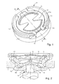
- the Figures 1 and 2 illustrate an inverted double-cone device that is currently used in timepieces on the market.
- the kitten 20 is held in a housing 6 of the support 1 by a spring 10 which comprises in this example radial extensions 9 compressing the stone against pivot 5.
- the housing 6 comprises two bearing surfaces 7, 7a cones inverted on which support complementary 8a, 8a litters of the kitten 20, said litters to be executed with very high accuracy.
- the spring 10 acts alone to bring the balance shaft 3 back to its initial position.
- the spring 10 is dimensioned to have a limit of displacement so that beyond this limit, the balance shaft 3 comes into contact with abutments 14 allowing said axis 3 to absorb the shock, which the rods 3a Axis 3 can not do without breaking.
- the spring 10 cooperates with the complementary inclined planes 7, 7a; 8, 8a to refocus the kitten 20.
- Such bearings have for example been sold under the trademark Incabloc®.
- These springs can be made of phynox or brass and are manufactured by traditional means of cutting.
- shock absorbing bearings are removable. Indeed, it is expected that these shock absorbing bearings can be dismountable for service after belly and maintenance operations. Shock absorbing bearings are thus obtained, the mounting of which is not easy. Indeed, some parts such as the support 1 and the spring 10 must be oriented and manipulated in a certain way during the assembly operation to assemble the damping bearing. Therefore, not only the component parts of the shock-absorbing bearing are complex but also the automation total assembly is not possible and makes said shock absorbing bearing more expensive.
- the object of the invention is to overcome the drawbacks of the prior art by proposing to provide a non-removable shock-absorbing bearing for a timepiece and easy to assemble.
- the invention relates to a shock-absorbing bearing for an axis of a mobile of a timepiece, said bearing comprising a support provided with a housing adapted to receive a pivot module arranged to cooperate with said axis. said bearing further comprising elastic means arranged to exert on said pivot module at least one axial force to maintain said module in its housing, characterized in that the elastic means are fixed permanently to the support by a material connection between said means elastic and support.
- a first advantage of the present invention is to provide a non-removable shockproof system simple to perform and assemble. Indeed, the present invention has the advantage of having parts that are placed on each other without them having to be manipulated in a particular way. Thus, the assembly process can be automated. This simplicity of the parts and the assembly process makes it possible to have a cheap shock absorber.
- the elastic means are fixed on the support by welding / soldering.
- the elastic means are fixed on the support by gluing.
- the elastic means comprise a spring ring having at least one internal radial extension extending towards the center of said spring ring.
- said spring ring comprises at least two specific zones of fasteners for fixing said spring ring to the support.
- said spring ring comprises at least two external radial extensions extending outwardly of said spring ring serving as specific zones of fasteners.
- the spring ring comprises three external radial extensions and three internal radial extensions.
- the present invention also relates to a watch movement comprising a plate and at least one bridge, said plate comprising an orifice.
- a shock absorbing bearing according to the invention.
- the present invention also relates to a watch movement comprising a plate and at least one bridge, said at least one bridge comprising an orifice.
- a shock absorbing bearing according to the invention
- the support of the damping bearing and said plate are monobloc.
- the support of the damping bearing and said at least one bridge are monobloc.
- the invention also relates to a timepiece comprising a middle part closed by a box and a base, the timepiece comprises a watch movement according to the invention.
- the present invention proceeds from the general inventive idea of providing a simple, non-removable shock absorber system.
- This shock absorber system is arranged to be mounted on a plate and / or at least one bridge of a watch movement.
- the watch movement is placed in a timepiece comprising a middle part closed by a bottom and an ice.
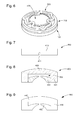
- FIG. 3 shows a shock-absorbing bearing, also called an anti-shock system 100.
- This shock-absorbing bearing 100 comprises a support 200.
- This support 200 is in the form of a base 201, provided with a hole 202, which extends a peripheral flange 203. The latter has an outer flank 204 and an inner flank 205.
- This flange 203 defines a housing 206 in which a pivot module 400 is inserted.
- This classic pivot module 400 comprises a kitten 401, that is to say a piece having a central circular orifice and an outer wall and an inner wall.
- a pierced stone 402 whose diameter corresponds to that of the central orifice.
- the inner wall includes a shoulder so that a counter pivot stone 403 can be attached.
- the pivot module 400 is then placed in the housing 206 of the support 200 and cooperates with the shank of an axis.
- the support 200, the housing 206 and the pivot module 400 are of circular shape.
- the shock absorbing bearing 100 further comprises elastic means 300 which are arranged to cooperate with the pivot module 400 so as to dampen the shocks and to bring the pivot module 400 back to its rest position when the stress related to shocks fades. .
- the elastic means 300 are fixed so as to be integral with the support 200. It is understood that the elastic means 300, once attached to the support 200, can no longer be separated, separated from the support.
- the elastic means 300 are permanently fixed to the support 200. The fixing of the elastic means 300 to the support 200 is therefore final. To do this, the elastic means 300 are fixed on the support 200 by welding or soldering or gluing. There is then a material connection between the elastic means 300 and the support 200. This link may be glue or solder or solder.
- the elastic means 300 form a cover placed on the support which maintains the pivot module 400 in the housing 206, the anti-shock system 100 thus becoming non-removable.
- This attachment to the support 200 is at the flange 203.
- the flange 203 has at its end 207, a surface 207a acting as a bearing surface on which the elastic means 300 can be fixed.
- the outer flank 204 of the support 200 may also act as a surface on which the elastic means 300 are fixed.
- an axial assembly is used.
- the first step is therefore to provide the support 200.
- it equips the pivot module 400 which is placed in the housing 206 of the support 200. It comes, then, place and fix the elastic means 300.
- the elastic means 300 are simply placed on the support 200. Glue or solder points are then applied to fix said elastic means 300.
- the elastic means 300 are in the form of a spring ring 301.
- This spring ring 301 is of the flat type, that is to say that it consists of a metal strip that is to say which has a width greater than the thickness.
- the spring ring 301 comprises internal radial extensions 302. These internal radial extensions 302 are constituted by the band forming the ring 301 which is bent inwards towards the inside. These inner radial extensions 301 are, preferably, evenly distributed over the flat ring 301 so that the spring ring 301 can act in a homogeneous manner as visible to the ring 301. figure 4 .
- the fixing the spring ring 301 to the support 200 is at the level of the circular portions 303 located between the inner radial extensions 302.
- the spring ring 301 may be made of a metallic material such as brass or any other material that can be used in the applications watchmaking.
- the spring ring 301 comprises specific zones of fasteners 304 as visible at figures 5 and 6 . Indeed, in the case of the spring ring 301 visible at the figure 4 the attachment to the support 200 by the circular portions 303 can cause a change in the properties of the spring ring 301.
- the specific zones of fasteners 304 are zones designed to limit the influence of the fixing by welding or gluing on the properties of said spring ring 301. These zones are in the form of external radial extensions 304a extending towards the outside of the ring 301. It is therefore understood that these specific areas of fasteners 304 are constituted by the band forming the ring 301 which is bent outwardly of the ring 301. Preferably, the curvature of the extensions external radial 304a is less pronounced than those of the inner radial extensions 302. It is understood that the distance between the ends of the outer radial extensions 304a and the band forming the ring 301 is greater than the distance between the ends of the extensions.
- the spring ring 301 according to this variant is advantageously dimensioned so that, when fixing said ring 301 to the support 200 , only the specific zones of fasteners 304 formed by the external radial extensions 304a are in contact with the support 200 for fixing. This configuration allows areas other than these specific areas of fasteners 304 to deform freely when axial stress is applied to the pivot module 400 by the axis.
- the spring ring 301 is arranged to have three internal radial extensions 302 and three specific zones of fasteners 304. that is, three external radial extensions 304a.
- the three internal radial extensions 302 are arranged to be offset from each other by 120 °.
- the three outer radial extensions 304a are arranged to be offset from each other by 120 °.
- the arrangement of the outer radial extensions 304a and the inner radial extensions 302 is such that the outer radial extensions 304a and the inner radial extensions 302 are alternated and offset 60 ° from each other. It will be understood that between two external radial extensions 304a there is an internal radial extension 302.
- the advantage of the shock absorbing bearing 100 is to have no specific orientation. Indeed, as all the constituent parts of said shockproof system 100 are circular, there is no need to orient them relative to each other.
- the support 200 has no particular areas on which the spring ring 301 must be fixed. In this way, the assembly method of such a shockproof system 100 can be automated to the maximum.
- the internal flank 205 has an inclined portion allowing a better centering of the pivot module 400.
- the axis exerts an axial force on the pivot module 400 so that it lifts and deforms the elastic means 300.
- These elastic means 300 hold the pivot module 400 so that, when the latter is no longer subjected to a stress, the elastic means 300 take up their rest position and press the pivot module 400 into position.
- housing 206 the pivot module 400 is lifted from the housing 206 by the axis, it is possible that the pivot module 400 is offsets under the effect of a force such as gravity and moves radially.
- the pivot module 400 is in the monobloc form.
- the pivot module 400 comprises a single stone 410.
- This single stone 410 is cylindrical in shape having a small height relative to the radius.
- This single stone 410 comprises, at its central axis, a blind hole 411 in which the spindle of the axis can be inserted.
- This single-stone configuration 410 makes it possible to have a more compact and simplified pivot module 400 since it makes it possible to have a shockproof system 100 consisting of only three parts: the support 200, the single stone 410 and the spring ring 301. Therefore, the dimensions of the support 200 can be reduced.
- the pierced stone 430 and the pivoting stone 420 are fixed to each other without the intermediary of a kitten.
- the pivoting stone 420 serves as a kitten.
- the counter-pivot stone 420 is then provided with a peripheral rim 421 defining a housing 422 in which the pierced stone 430 is placed.
- This alternative makes it possible to have a simplified pivot module 400 but having dimensions similar to those of a pivot module 400 with a kitten. The dimensions of the support thus remain unchanged to adapt to this alternative.
- the pierced stone 450 and the counter-pivot stone 440 are monoblock.
- the pivot module 400 resembles the pivot module of the second alternative except that instead of having the pierced stone 450 and the counter-pivoting rock 440 fixed to one another, they are directly integral through a attachment element 445.
- the support is monobloc with the place on which the shock absorbing bearing is fixed.
- a shock absorbing bearing is arranged to be installed at a bridge or a turntable of a watch movement.
- This clock movement has through orifices made on the plate or bridges. In these orifices, an anti-shock system 100 are inserted, each orifice being sized so that the support 200 can be driven there.
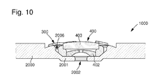
- the support is directly carried out on the bridge or bridges and the plate to form a damping assembly 1000.
- the plate and / or bridges form the support 2000 machined to reveal a base 2001 including a hole 2002
- the support 2000 has a housing 2006 in which the pivot module 400 is placed.
- the spring ring 301 is fixed on the upper face of the support 2000. This variant also allows to have one piece less because the support 200 no longer exists.
Priority Applications (5)
| Application Number | Priority Date | Filing Date | Title |
|---|---|---|---|
| EP12173045.1A EP2677371A1 (de) | 2012-06-21 | 2012-06-21 | Nicht demontierbares stoßsicheres System für Uhr |
| EP13732869.6A EP2864843B1 (de) | 2012-06-21 | 2013-06-19 | Nicht demontierbares stossdämpfungssystem für eine uhr |
| JP2015517751A JP6219941B2 (ja) | 2012-06-21 | 2013-06-19 | 計時器用の分解不能な耐衝撃システム |
| PCT/EP2013/062801 WO2013190011A2 (fr) | 2012-06-21 | 2013-06-19 | Système antichoc non démontable pour pièce d'horlogerie |
| US14/409,696 US9678479B2 (en) | 2012-06-21 | 2013-06-19 | Non-dismantlable shock-proof system for timepiece |
Applications Claiming Priority (1)
| Application Number | Priority Date | Filing Date | Title |
|---|---|---|---|
| EP12173045.1A EP2677371A1 (de) | 2012-06-21 | 2012-06-21 | Nicht demontierbares stoßsicheres System für Uhr |
Publications (1)
| Publication Number | Publication Date |
|---|---|
| EP2677371A1 true EP2677371A1 (de) | 2013-12-25 |
Family
ID=48741074
Family Applications (2)
| Application Number | Title | Priority Date | Filing Date |
|---|---|---|---|
| EP12173045.1A Withdrawn EP2677371A1 (de) | 2012-06-21 | 2012-06-21 | Nicht demontierbares stoßsicheres System für Uhr |
| EP13732869.6A Active EP2864843B1 (de) | 2012-06-21 | 2013-06-19 | Nicht demontierbares stossdämpfungssystem für eine uhr |
Family Applications After (1)
| Application Number | Title | Priority Date | Filing Date |
|---|---|---|---|
| EP13732869.6A Active EP2864843B1 (de) | 2012-06-21 | 2013-06-19 | Nicht demontierbares stossdämpfungssystem für eine uhr |
Country Status (4)
| Country | Link |
|---|---|
| US (1) | US9678479B2 (de) |
| EP (2) | EP2677371A1 (de) |
| JP (1) | JP6219941B2 (de) |
| WO (1) | WO2013190011A2 (de) |
Cited By (2)
| Publication number | Priority date | Publication date | Assignee | Title |
|---|---|---|---|---|
| CN105700329A (zh) * | 2016-05-06 | 2016-06-22 | 深圳市中世纵横设计有限公司 | 一种具有抗震功能的镂空表结构 |
| JP2017009601A (ja) * | 2015-06-16 | 2017-01-12 | ニヴァロックス−ファー ソシエテ アノニム | 分離した溶接表面をもつ部品を有する計時器構成要素 |
Families Citing this family (5)
| Publication number | Priority date | Publication date | Assignee | Title |
|---|---|---|---|---|
| EP3106934A1 (de) * | 2015-06-16 | 2016-12-21 | Montres Breguet S.A. | Magnetische schwenkeinrichtung einer welle in einem uhrwerk |
| EP3182211A1 (de) * | 2015-12-17 | 2017-06-21 | Nivarox-FAR S.A. | Verbundwerkstück mit unter spannung stehenden elastischen mitteln |
| EP3543800B1 (de) * | 2018-03-20 | 2021-11-10 | Omega SA | System eines drehbaren aussenrings einer armbanduhr, das einen federring umfasst |
| EP3543798B1 (de) * | 2018-03-20 | 2020-12-30 | Omega SA | System eines drehbaren aussenrings einer armbanduhr, das mit mindestens einem federnden arm ausgestattet ist |
| EP3916489A1 (de) * | 2020-05-29 | 2021-12-01 | Rolex Sa | Dämpfungsfeder, lagerkörper und lager für uhr |
Citations (3)
| Publication number | Priority date | Publication date | Assignee | Title |
|---|---|---|---|---|
| CH301023A (fr) * | 1952-08-14 | 1954-08-31 | Ciana Jean | Palier pour mobile de montre. |
| FR2197423A5 (de) * | 1972-08-25 | 1974-03-22 | Cattin Sa Ets | |
| CH698675B1 (fr) * | 2005-07-08 | 2009-09-30 | Patek Philippe Sa | Palier amortisseur de chocs pour pièce d'horlogerie. |
Family Cites Families (20)
| Publication number | Priority date | Publication date | Assignee | Title |
|---|---|---|---|---|
| CH201334A (fr) * | 1937-11-08 | 1938-11-30 | Fritz Marti | Dispositif de fixation élastique de palier. |
| CH302821A (fr) * | 1950-10-19 | 1954-10-31 | Parechoc Sa | Dispositif de montage d'un contre-pivot d'axe d'horlogerie sur son support. |
| CH291856A (fr) | 1951-09-27 | 1953-07-15 | Vuilleumier Marcel | Palier pour piéce d'horlogerie. |
| CH304438A (fr) * | 1951-11-07 | 1955-01-15 | Voumard Bertrand | Palier amortisseur de chocs. |
| US2891379A (en) * | 1953-12-17 | 1959-06-23 | Seitz Pierre | Shock-absorbing bearing |
| CH328802A (fr) | 1955-02-18 | 1958-03-31 | Eirsmann Gerard | Palier |
| FR1143836A (fr) | 1956-02-24 | 1957-10-04 | Ile D Etudes De Brevets D App | Perfectionnement aux paliers amortisseurs de chocs plus particulièrement destinés aux mécanismes d'horlogerie |
| US2973618A (en) * | 1958-01-11 | 1961-03-07 | Morf Pierre | Shock-absorbing pivot bearing |
| CH356723A (de) | 1959-08-22 | 1961-08-31 | Steffen Giovanni | Stossdämpfendes Lager, insbesondere für die Lagerung der Zapfen von Uhrwellen |
| GB1029700A (en) | 1963-05-24 | 1966-05-18 | Parechoc Sa | A shock-damping bearing for the movement of a time-piece or other small mechanism and a method for the manufacture thereof |
| US3306028A (en) * | 1966-01-04 | 1967-02-28 | Citizen Watch Co Ltd | Shock-proof device for watches |
| US3500632A (en) * | 1967-09-11 | 1970-03-17 | Portescap Le Porte | Bearing for a timepiece pivot |
| JPS522543A (en) * | 1975-06-24 | 1977-01-10 | Citizen Watch Co Ltd | Vibration proof bearing |
| FR2336588A1 (fr) | 1975-12-24 | 1977-07-22 | Epsilon Sarl | Ressort pour palier amortisseur de chocs |
| CH615311B (fr) * | 1976-11-22 | Ebauches Bettlach Sa | Palier amortisseur de chocs pour mouvement d'horlogerie. | |
| JPWO2002050616A1 (ja) * | 2000-12-20 | 2004-04-22 | セイコーインスツルメンツ株式会社 | 姿勢検出装置付き機械式時計及び姿勢検出装置 |
| WO2004068247A1 (ja) * | 2003-01-28 | 2004-08-12 | Seiko Epson Corporation | 多機能時計 |
| DE602005006731D1 (de) * | 2005-03-23 | 2008-06-26 | Rolex Sa | Stoßdämpfende Lagerung für Uhren |
| JP2010256337A (ja) * | 2009-04-01 | 2010-11-11 | Seiko Epson Corp | 時計 |
| EP2469357B2 (de) * | 2010-12-21 | 2016-06-29 | The Swatch Group Research and Development Ltd. | Stoßdämpfer-Gleitlager für eine sich drehende Triebfeder einer Uhr |
-
2012
- 2012-06-21 EP EP12173045.1A patent/EP2677371A1/de not_active Withdrawn
-
2013
- 2013-06-19 WO PCT/EP2013/062801 patent/WO2013190011A2/fr active Application Filing
- 2013-06-19 EP EP13732869.6A patent/EP2864843B1/de active Active
- 2013-06-19 US US14/409,696 patent/US9678479B2/en active Active
- 2013-06-19 JP JP2015517751A patent/JP6219941B2/ja active Active
Patent Citations (3)
| Publication number | Priority date | Publication date | Assignee | Title |
|---|---|---|---|---|
| CH301023A (fr) * | 1952-08-14 | 1954-08-31 | Ciana Jean | Palier pour mobile de montre. |
| FR2197423A5 (de) * | 1972-08-25 | 1974-03-22 | Cattin Sa Ets | |
| CH698675B1 (fr) * | 2005-07-08 | 2009-09-30 | Patek Philippe Sa | Palier amortisseur de chocs pour pièce d'horlogerie. |
Cited By (2)
| Publication number | Priority date | Publication date | Assignee | Title |
|---|---|---|---|---|
| JP2017009601A (ja) * | 2015-06-16 | 2017-01-12 | ニヴァロックス−ファー ソシエテ アノニム | 分離した溶接表面をもつ部品を有する計時器構成要素 |
| CN105700329A (zh) * | 2016-05-06 | 2016-06-22 | 深圳市中世纵横设计有限公司 | 一种具有抗震功能的镂空表结构 |
Also Published As
| Publication number | Publication date |
|---|---|
| JP6219941B2 (ja) | 2017-10-25 |
| JP2015520390A (ja) | 2015-07-16 |
| US20150198926A1 (en) | 2015-07-16 |
| WO2013190011A3 (fr) | 2014-03-20 |
| US9678479B2 (en) | 2017-06-13 |
| EP2864843A2 (de) | 2015-04-29 |
| EP2864843B1 (de) | 2019-12-11 |
| WO2013190011A2 (fr) | 2013-12-27 |
Similar Documents
| Publication | Publication Date | Title |
|---|---|---|
| EP2864843B1 (de) | Nicht demontierbares stossdämpfungssystem für eine uhr | |
| EP1696286B1 (de) | Stoßdämpfende Uhrenlagerung | |
| EP3220211B1 (de) | Stosssicherungssystem mit rotationssperre | |
| EP2469357B2 (de) | Stoßdämpfer-Gleitlager für eine sich drehende Triebfeder einer Uhr | |
| EP3004992A1 (de) | Bajonettstossdämpfer | |
| EP2206022B1 (de) | Stossdämpfende lagerung für eine uhr | |
| EP2015147B2 (de) | Stoßdämpfer-Gleitlager für eine Uhr | |
| EP3080666B1 (de) | Verfahren zur herstellung eines stosssicheres system aus zwei verschiedenen materialien für uhr | |
| EP3011396B1 (de) | Stossdämpfungssystem mit sicherer montage | |
| WO2013190012A1 (fr) | Systeme antichoc a montage simplifie pour piece d'horlogerie | |
| CH698675B1 (fr) | Palier amortisseur de chocs pour pièce d'horlogerie. | |
| CH706639A2 (fr) | Palier antichoc non demontable pour pièce d'horlogerie. | |
| EP3291026A1 (de) | Stossdämpfer-gleitlager für eine uhr | |
| CH706640A2 (fr) | Palier antichoc pour pièce d'horlogerie. | |
| CH708223A2 (fr) | Dispositif amortisseur de chocs pour pièces d'horlogerie. | |
| CH712187A2 (fr) | Dispositif amortisseur de chocs pour un axe d'un mobile d'une pièce d'horlogerie comportant un anneau ressort monté à baïonnette. | |
| CH708089A2 (fr) | Amortisseur de choc monobloc avec lubrification. | |
| EP3916489A1 (de) | Dämpfungsfeder, lagerkörper und lager für uhr | |
| CH708090A2 (fr) | Amortisseur de choc à baïonnette. | |
| CH704245A2 (fr) | Palier amortisseur de chocs pour un mobile tournant d'un mouvement d'horlogerie. | |
| CH705908A2 (fr) | Palier antichoc pour pièce d'horlogerie, en élastomère. | |
| CH710490A2 (fr) | Ensemble de maintien ou d'appui d'un ressort spiral d'horlogerie. | |
| WO2013087453A1 (fr) | Systeme antichoc pour piece d'horlogerie en elastomere |
Legal Events
| Date | Code | Title | Description |
|---|---|---|---|
| PUAI | Public reference made under article 153(3) epc to a published international application that has entered the european phase |
Free format text: ORIGINAL CODE: 0009012 |
|
| AK | Designated contracting states |
Kind code of ref document: A1 Designated state(s): AL AT BE BG CH CY CZ DE DK EE ES FI FR GB GR HR HU IE IS IT LI LT LU LV MC MK MT NL NO PL PT RO RS SE SI SK SM TR |
|
| AX | Request for extension of the european patent |
Extension state: BA ME |
|
| STAA | Information on the status of an ep patent application or granted ep patent |
Free format text: STATUS: THE APPLICATION IS DEEMED TO BE WITHDRAWN |
|
| 18D | Application deemed to be withdrawn |
Effective date: 20140626 |