EP2677245A2 - Lüftungssystem zur Belüftung und/oder zur Entlüftung eines Raumes - Google Patents
Lüftungssystem zur Belüftung und/oder zur Entlüftung eines Raumes Download PDFInfo
- Publication number
- EP2677245A2 EP2677245A2 EP13169750.0A EP13169750A EP2677245A2 EP 2677245 A2 EP2677245 A2 EP 2677245A2 EP 13169750 A EP13169750 A EP 13169750A EP 2677245 A2 EP2677245 A2 EP 2677245A2
- Authority
- EP
- European Patent Office
- Prior art keywords
- channel
- ventilation system
- flow
- control
- air
- Prior art date
- Legal status (The legal status is an assumption and is not a legal conclusion. Google has not performed a legal analysis and makes no representation as to the accuracy of the status listed.)
- Granted
Links
Images

Classifications
-
- F—MECHANICAL ENGINEERING; LIGHTING; HEATING; WEAPONS; BLASTING
- F24—HEATING; RANGES; VENTILATING
- F24F—AIR-CONDITIONING; AIR-HUMIDIFICATION; VENTILATION; USE OF AIR CURRENTS FOR SCREENING
- F24F7/00—Ventilation
- F24F7/007—Ventilation with forced flow
- F24F7/013—Ventilation with forced flow using wall or window fans, displacing air through the wall or window
-
- F—MECHANICAL ENGINEERING; LIGHTING; HEATING; WEAPONS; BLASTING
- F24—HEATING; RANGES; VENTILATING
- F24F—AIR-CONDITIONING; AIR-HUMIDIFICATION; VENTILATION; USE OF AIR CURRENTS FOR SCREENING
- F24F11/00—Control or safety arrangements
- F24F11/0001—Control or safety arrangements for ventilation
-
- F—MECHANICAL ENGINEERING; LIGHTING; HEATING; WEAPONS; BLASTING
- F24—HEATING; RANGES; VENTILATING
- F24F—AIR-CONDITIONING; AIR-HUMIDIFICATION; VENTILATION; USE OF AIR CURRENTS FOR SCREENING
- F24F11/00—Control or safety arrangements
- F24F11/70—Control systems characterised by their outputs; Constructional details thereof
- F24F11/72—Control systems characterised by their outputs; Constructional details thereof for controlling the supply of treated air, e.g. its pressure
- F24F11/74—Control systems characterised by their outputs; Constructional details thereof for controlling the supply of treated air, e.g. its pressure for controlling air flow rate or air velocity
- F24F11/745—Control systems characterised by their outputs; Constructional details thereof for controlling the supply of treated air, e.g. its pressure for controlling air flow rate or air velocity the air flow rate increasing with an increase of air-current or wind pressure
-
- F—MECHANICAL ENGINEERING; LIGHTING; HEATING; WEAPONS; BLASTING
- F24—HEATING; RANGES; VENTILATING
- F24F—AIR-CONDITIONING; AIR-HUMIDIFICATION; VENTILATION; USE OF AIR CURRENTS FOR SCREENING
- F24F11/00—Control or safety arrangements
- F24F11/70—Control systems characterised by their outputs; Constructional details thereof
- F24F11/72—Control systems characterised by their outputs; Constructional details thereof for controlling the supply of treated air, e.g. its pressure
- F24F11/74—Control systems characterised by their outputs; Constructional details thereof for controlling the supply of treated air, e.g. its pressure for controlling air flow rate or air velocity
- F24F11/75—Control systems characterised by their outputs; Constructional details thereof for controlling the supply of treated air, e.g. its pressure for controlling air flow rate or air velocity for maintaining constant air flow rate or air velocity
-
- F—MECHANICAL ENGINEERING; LIGHTING; HEATING; WEAPONS; BLASTING
- F24—HEATING; RANGES; VENTILATING
- F24F—AIR-CONDITIONING; AIR-HUMIDIFICATION; VENTILATION; USE OF AIR CURRENTS FOR SCREENING
- F24F7/00—Ventilation
- F24F2007/0025—Ventilation using vent ports in a wall
-
- F—MECHANICAL ENGINEERING; LIGHTING; HEATING; WEAPONS; BLASTING
- F24—HEATING; RANGES; VENTILATING
- F24F—AIR-CONDITIONING; AIR-HUMIDIFICATION; VENTILATION; USE OF AIR CURRENTS FOR SCREENING
- F24F11/00—Control or safety arrangements
- F24F11/0001—Control or safety arrangements for ventilation
- F24F2011/0002—Control or safety arrangements for ventilation for admittance of outside air
-
- Y—GENERAL TAGGING OF NEW TECHNOLOGICAL DEVELOPMENTS; GENERAL TAGGING OF CROSS-SECTIONAL TECHNOLOGIES SPANNING OVER SEVERAL SECTIONS OF THE IPC; TECHNICAL SUBJECTS COVERED BY FORMER USPC CROSS-REFERENCE ART COLLECTIONS [XRACs] AND DIGESTS
- Y02—TECHNOLOGIES OR APPLICATIONS FOR MITIGATION OR ADAPTATION AGAINST CLIMATE CHANGE
- Y02B—CLIMATE CHANGE MITIGATION TECHNOLOGIES RELATED TO BUILDINGS, e.g. HOUSING, HOUSE APPLIANCES OR RELATED END-USER APPLICATIONS
- Y02B30/00—Energy efficient heating, ventilation or air conditioning [HVAC]
- Y02B30/70—Efficient control or regulation technologies, e.g. for control of refrigerant flow, motor or heating
Definitions
- the invention relates to a ventilation system for ventilation and / or ventilation of a room with an extending between a building exterior side opening and a space inside opening extending channel, wherein in the channel an air conveyor is provided.
- Known ventilation systems have a channel which extends between a building exterior side opening and a space inside opening. In the channel, an air conveyor is provided.
- Decentralized ventilation systems mainly use air handling units with integrated volume flow control. With changing differential pressures, as e.g. In the event of wind pressure or wind suction on the facade, the air handling units change their speed in order to keep the volume flow constant.
- a disadvantage proves that air handling devices with integrated flow control operate in the lower volume flow range with an extended tolerance band, so that, for example, at large differential pressures no sufficient control accuracy is guaranteed.
- the object of the invention is to avoid the aforementioned disadvantages and to provide a ventilation system that allows a more precise control or regulation of the volume flow in ventilation systems, especially in decentralized ventilation systems.
- the ventilation system has a return, which, viewed in the flow direction branches off after the air conveyor from the channel and which opens into a seen in the channel in the flow direction upstream of the air conveyor distribution device opens, for distribution, in particular for control, the shares of the return and through is formed in the flow direction before the distributor located channel each flowing air flow is formed or the ventilation system has a return, which branches off from a seen in the flow direction downstream of the air conveyor distribution device and flows in the flow direction before the air conveyor into the channel, wherein the distribution device for distribution, in particular for regulating the proportions of the return and is formed by the channel located in the flow direction after the distribution device each flowing air stream.
- the distribution device may for example have a flap, which is preferably pivotable continuously between two end positions. In one end position, the return is completely closed. In the other end position, depending on the arrangement of the distribution device in the two alternative embodiments of the ventilation system, either the channel located in the flow direction before the distribution device or seen in the flow direction after the distribution device located channel completely closed. Of course, intermediate positions are possible.
- a drive may be provided.
- other suitable actuators such as a bellows, which contracts or is inflated depending on the prevailing pressure conceivable.
- the position of the distribution device by means of a control or regulating device or a drive connected to a control or regulating device is variable.
- the connection between the individual components for example between the drive and the control or regulating device, can be designed to be wired or radio-based.
- the control device works at high differential pressures as flow limiters.
- the ventilation system has a return, which, viewed in the flow direction branches off after the air conveyor from the channel and in a seen in the channel in the flow direction in front of the air conveyor arranged distributing device, which is designed for distribution, in particular for controlling the proportions of each of the recirculation and through the channel located in the flow direction before the distribution channel each flowing air stream, in the flow direction located in front of the distributor channel at least one with the Control or regulating device connected sensor for determining the local volume flow or the flow rate can be provided. This allows deviations to be measured, for example, in the velocity of the volume flow flowing in the channel located in front of the distributor. Such deviations can occur when the wind loads acting on a facade change. At least one sensor may be radio-based or wired connected to at least one other component, such as the control or regulating device.
- At least one sensor connected to the control or regulating device can be provided for determining the local volume flow or the flow velocity in the channel located in the flow direction after the distribution device. This allows deviations, for example, in the speed of the volume flow flowing in the channel located downstream of the distributor be measured. Such deviations can occur when the wind loads acting on a facade change.
- At least one sensor may be radio-based or wired connected to at least one other component, such as the control or regulating device.
- At least one sensor can be designed as a pressure sensor or the like.
- other sensor types such as e.g. a pitot tube or a hot wire anemometer, possible.
- the air conveyor may be connected to a constant speed control or constant volumetric flow delivery.
- the control can be integrated directly into the air conveyor. It is of course also possible that this regulation is provided in a separate component. Of course, it is also possible that the air conveyor is connected to a suitable control or regulating device in order to control or regulate the power accordingly.
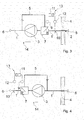
- the figures show the basic structure of a decentralized ventilation system.
- the ventilation system has a channel 1 extending between a building exterior side opening 2 and a space inside opening.
- an air conveyor 3 is provided in the channel 1.
- the building exterior side opening 2 is located in an indicated wall 4.
- the space inside opening is not shown. However, it is located in the region of the end of the channel 1, which is opposite to the end with the building exterior side opening 2 opposite.
- the ventilation system comprises a return 5.
- the return line 5 branches off the channel 1 downstream of the air conveying device 3 and opens into a distributor 7 arranged in the channel 1 in the flow direction 6, in front of the air conveying device 3.
- the distribution device 7 is arranged in the channel 1 in the flow direction 6 after the air conveyor 3.
- the return line 5 branches off from the distributor device 7 and, as seen in the flow direction 6, flows back into the channel 1 before the air conveyor device 3.
- the distributor 7 has a suitable component, which in the embodiments of the FIGS. 1 and 3 a distribution, in particular a control, which allows proportions of the air flowing through the return 5 and through the channel 1 located in front of the distributor device 7 in the flow direction 6.
- the distribution device 7 a distribution, in particular a control, the proportions of the air flowing through the recirculation 5 and by the channel 6 located in the flow direction 6 after the distribution device 7 respectively flowing air stream.
- the distribution device 7 as a component on a flap 8, which can be adjusted by a drive 9 in position.
- Each distribution device 7 is preferably pivotable continuously between its two respective end positions. In one end position, the return 5 is completely closed. In the other end position is in the embodiments of the Fig. 1 and 3 seen in the flow direction 6 located in front of the distributor 7 channel 1 completely closed.
- FIGS. 1 and 3 is in the direction of flow 6 seen in front of the distributor 7 located channel 1, a sensor 10 is provided.
- the sensor 10 is arranged in the channel 1 in the flow direction 6 after the distribution device 7.
- the sensor 10 is used to determine the local volume flow or the local flow velocity.
- the sensor 10 is connected to a control or regulating device 11. Between the sensor 10 and the control and / or regulating device 11, a transducer 12 is provided, which converts the signal detected by the sensor 10 into a corresponding voltage signal.
- a reference variable 13 is indicated. This is an externally supplied to the control or regulating device 11 size, which should follow the controlled variable in a predetermined dependence.
- the reference variable 13 determines in the control device 11 to be complied with the setpoint of the controlled variable.
- the reference variable 13 may be constant or have a value dependent on time or other quantities.
- the air conveyor 3 has a control 14, not shown, in order to ensure a constant speed or a constant volume flow promotion.
- the control 14 can be, for example, an internally built-in control, which automatically adapts the speed to the respective situation in the case of a volume-constant air conveying device 3.
- the nominal values for the air conveyor 3 and for the distributor 7 should ideally be the same as possible. Due to the expected control tolerances of the actual value of the air conveyor 3 of the actual value of the Diverge 7 differ. If the actual value of the air conveying device 3 is above the actual value of the distributing device 7, the difference between the actual values (small partial volume flow) is conducted via the return 5 from the pressure side of the air conveying device 3 to the suction side of the air conveying device 3.
- Fig. 1 and 3 show the first embodiment of the ventilation system according to the invention in the exhaust air operation or in the outside air operation, wherein in Fig. 1 the exhaust air operation and in Fig. 3 the outside air operation is shown.
- the distribution device 7 throttles the channel 1 as the facade negative pressure increases, while the rotational speed of the air conveyor 3 is reduced. An uncontrolled exhaust air flow from the channel 1 via the building exterior side opening 2 into the open is thus prevented. Differences in the exhaust air volume flow between the actual value of the air conveyor 3 and the actual value of the distributor 7 are compensated via the feedback 5.
- the distribution device 7 throttles the channel 1 as the facade overpressure increases, while the rotational speed of the air conveyor 3 is reduced. An uncontrolled flow of outside air ( 3 and 4 ) over the channel 1 in the room is thus prevented. Differences in the outside air volume flow between the actual value of the air conveyor 3 and the actual value of the distributor 7 are compensated via the feedback 5.
- the distribution device 7 continues to open the channel 1 as the facade negative pressure increases, so that the recirculation 5 is increasingly throttled. Parallel to this, the speed of the air conveyor 3 increases until the setpoint of the outside air volume flow is reached.
- each ventilation system allows a precise control or regulation of the respective volume flow in differently designed ventilation systems, in particular in decentralized ventilation systems.
- variable resistors as they can occur, for example, by dirty filters, the entire system reacts as with variable wind loads.
- each ventilation system is designed either for the outside air or for the exhaust air operation. In such a case, for the ventilation of a Room at least two appropriate ventilation systems required.
- a ventilation system is sufficient. In one direction of rotation a ventilation (outside air operation) and in the other direction of rotation of the air conveyor 3 a vent (exhaust air operation) is achieved.
Landscapes
- Engineering & Computer Science (AREA)
- Chemical & Material Sciences (AREA)
- Combustion & Propulsion (AREA)
- Mechanical Engineering (AREA)
- General Engineering & Computer Science (AREA)
- Physics & Mathematics (AREA)
- Fluid Mechanics (AREA)
- Ventilation (AREA)
- Duct Arrangements (AREA)
Abstract
Description
- Die Erfindung betrifft ein Lüftungssystem zur Belüftung und/oder zur Entlüftung eines Raumes mit einem sich zwischen einer gebäudeaußenseitigen Öffnung und einer rauminnenseitigen Öffnung erstreckenden Kanal, wobei in dem Kanal eine Luftfördereinrichtung vorgesehen ist.
- Bekannte Lüftungssysteme weisen einen Kanal auf, der sich zwischen einer gebäudeaußenseitigen Öffnung und einer rauminnenseitigen Öffnung erstreckt. In dem Kanal ist eine Luftfördereinrichtung vorgesehen. In dezentralen Lüftungssystemen werden vorwiegend Luftfördereinrichtungen mit integrierter Volumenstromregelung eingesetzt. Bei wechselnden Differenzdrücken, wie sie z.B. bei Winddruck oder Windsog auf der Fassade entstehen können, verändern die Luftfördereinrichtungen ihre Drehzahl, um den Volumenstrom konstant zu halten.
- Als Nachteil erweist sich, dass Luftfördereinrichtungen mit integrierter Volumenstromregelung im unteren Volumenstrombereich mit einem erweiterten Toleranzband arbeiten, so dass beispielsweise bei großen Differenzdrücken keine hinreichende Regelgenauigkeit gewährleistet ist.
- Aufgabe der Erfindung ist es, die vorgenannten Nachteile zu vermeiden und ein Lüftungssystem anzugeben, das eine präzisere Steuerung oder Regelung des Volumenstroms in Lüftungssystemen, insbesondere in dezentralen Lüftungssystemen, ermöglicht.
- Diese Aufgabe wird dadurch gelöst, dass
entweder - das Lüftungssystem eine Rückführung aufweist, die in Strömungsrichtung gesehen nach der Luftfördereinrichtung aus dem Kanal abzweigt und die in eine in dem Kanal in Strömungsrichtung gesehen vor der Luftfördereinrichtung angeordnete Verteileinrichtung mündet, die zur Verteilung, insbesondere zur Regelung, der Anteile des durch die Rückführung und durch den in Strömungsrichtung gesehen vor der Verteileinrichtung befindlichen Kanal jeweils strömenden Luftstroms ausgebildet ist
oder
das Lüftungssystem eine Rückführung aufweist, die aus einer in dem Kanal in Strömungsrichtung gesehen nach der Luftfördereinrichtung angeordneten Verteileinrichtung abzweigt und die in Strömungsrichtung gesehen vor der Luftfördereinrichtung in den Kanal mündet, wobei die Verteileinrichtung zur Verteilung, insbesondere zur Regelung, der Anteile des durch die Rückführung und durch den in Strömungsrichtung gesehen nach der Verteileinrichtung befindlichen Kanal jeweils strömenden Luftstroms ausgebildet ist. - Die Verteileinrichtung kann beispielsweise eine Klappe aufweisen, die vorzugsweise stufenlos zwischen zwei Endlagen verschwenkbar ist. In der einen Endlage wird die Rückführung vollständig verschlossen. In der anderen Endlage wird je nach Anordnung der Verteileinrichtung bei den beiden alternativen Ausgestaltungen des Lüftungssystems entweder der in Strömungsrichtung gesehen vor der Verteileinrichtung befindliche Kanal oder der in Strömungsrichtung gesehen nach der Verteileinrichtung befindliche Kanal vollständig verschlossen. Selbstverständlich sind auch Zwischenstellungen möglich.
- Zur Verstellung kann beispielsweise ein Antrieb vorgesehen sein. Selbstverständlich sind auch andere geeignete Aktoren, wie beispielsweise ein Balg, der sich in Abhängigkeit des herrschenden Druckes zusammenzieht oder aufgeblasen wird, denkbar. Durch das erfindungsgemäße Lüftungssystem kann das Toleranzband der Luftfördereinrichtung im unteren Volumenstrombereich verkleinert werden.
- Es bietet sich an, wenn die Stellung der Verteileinrichtung mittels einer Steuer- oder Regeleinrichtung oder eines mit einer Steuer- oder Regeleinrichtung verbundenen Antriebes veränderbar ist. Die Verbindung zwischen den einzelnen Komponenten, beispielsweise zwischen dem Antrieb und der Steuer- oder Regeleinrichtung, kann drahtgebunden oder funkbasiert ausgebildet sein. Die Regeleinrichtung funktioniert bei hohen Differenzdrücken als Volumenstrombegrenzer.
- Sofern das Lüftungssystem eine Rückführung aufweist, die in Strömungsrichtung gesehen nach der Luftfördereinrichtung aus dem Kanal abzweigt und die in eine in dem Kanal in Strömungsrichtung gesehen vor der Luftfördereinrichtung angeordnete Verteileinrichtung mündet, die zur Verteilung, insbesondere zur Regelung, der Anteile des durch die Rückführung und durch den in Strömungsrichtung gesehen vor der Verteileinrichtung befindlichen Kanal jeweils strömenden Luftstroms ausgebildet ist, kann in dem in Strömungsrichtung gesehen vor der Verteileinrichtung befindlichen Kanal zumindest ein mit der Steuer- oder Regeleinrichtung verbundener Sensor zur Bestimmung des dortigen Volumenstroms oder der Strömungsgeschwindigkeit vorgesehen sein. Damit können Abweichungen beispielsweise in der Geschwindigkeit des in dem vor der Verteileinrichtung befindlichen Kanal strömenden Volumenstroms gemessen werden. Derartige Abweichungen können auftreten, wenn sich die auf eine Fassade wirkenden Windlasten ändern. Zumindest ein Sensor kann funkbasiert oder auch drahtgebunden mit zumindest einer weiteren Komponente, beispielsweise der Steuer- oder Regeleinrichtung, verbunden sein.
- Sofern das Lüftungssystem eine Rückführung aufweist, die aus einer in dem Kanal in Strömungsrichtung gesehen nach der Luftfördereinrichtung angeordneten Verteileinrichtung abzweigt und die in Strömungsrichtung gesehen vor der Luftfördereinrichtung in den Kanal mündet, wobei die Verteileinrichtung zur Verteilung, insbesondere zur Regelung, der Anteile des durch die Rückführung und durch den in Strömungsrichtung gesehen nach der Verteileinrichtung befindlichen Kanal jeweils strömenden Luftstroms ausgebildet ist, kann in dem in Strömungsrichtung gesehen nach der Verteileinrichtung befindlichen Kanal zumindest ein mit der Steuer- oder Regeleinrichtung verbundener Sensor zur Bestimmung des dortigen Volumenstroms oder der Strömungsgeschwindigkeit vorgesehen sein. Damit können Abweichungen beispielsweise in der Geschwindigkeit des in dem nach der Verteileinrichtung befindlichen Kanal strömenden Volumenstroms gemessen werden. Derartige Abweichungen können auftreten, wenn sich die auf eine Fassade wirkenden Windlasten ändern. Zumindest ein Sensor kann funkbasiert oder auch drahtgebunden mit zumindest einer weiteren Komponente, beispielsweise der Steuer- oder Regeleinrichtung, verbunden sein.
- Zumindest ein Sensor kann als Drucksensor oder dergleichen ausgebildet sein. Selbstverständlich sind auch andere Sensortypen, wie z.B. ein Staurohr oder ein Hitzdrahtanemometer, möglich.
- Die Luftfördereinrichtung kann mit einer Regelung für eine konstante Drehzahl oder eine konstante Volumenstromförderung verbunden sein. Die Regelung kann in die Luftfördereinrichtung direkt integriert sein. Es ist auch selbstverständlich möglich, dass diese Regelung in einem getrennten Bauteil vorgesehen ist. Selbstverständlich ist es auch möglich, dass die Luftfördereinrichtung mit einer geeigneten Regel- oder Steuereinrichtung verbunden ist, um die Leistung entsprechend steuern oder regeln zu können.
- Im Folgenden werden in den Zeichnungen dargestellte Ausführungsbeispiele der Erfindung erläutert. Es zeigen:
- Fig. 1
- ein erstes Ausführungsbeispiel eines erfindungsgemäßen Lüftungssystems im Fortluftbetrieb,
- Fig. 2
- eine alternative Ausgestaltung eines erfindungsgemäßen Lüftungssystems im Fortluftbetrieb,
- Fig. 3
- den Gegenstand nach
Fig. 1 im Außenluftbetrieb und - Fig. 4
- den Gegenstand nach
Fig. 2 im Außenluftbetrieb. - In allen Figuren werden für gleiche bzw. gleichartige Bauteile übereinstimmende Bezugszeichen verwendet.
- Die Figuren zeigen den prinzipiellen Aufbau eines dezentralen Lüftungssystems. Das Lüftungssystem weist einen Kanal 1 auf, der sich zwischen einer gebäudeaußenseitigen Öffnung 2 und einer rauminnenseitigen Öffnung erstreckt. In dem Kanal 1 ist eine Luftfördereinrichtung 3 vorgesehen. Die gebäudeaußenseitige Öffnung 2 befindet sich in einer angedeuteten Wand 4. Die rauminnenseitige Öffnung ist nicht dargestellt. Sie befindet sich jedoch im Bereich des Endes des Kanals 1, das dem Ende mit der gebäudeaußenseitigen Öffnung 2 gegenüberliegend angeordnet ist.
- Zusätzlich umfasst das Lüftungssystem eine Rückführung 5. Bei den Ausführungsbeispielen nach den
Fig. 1 und3 zweigt die Rückführung 5 in Strömungsrichtung 6 gesehen nach der Luftfördereinrichtung 3 aus dem Kanal 1 ab und mündet in eine in dem Kanal 1 in Strömungsrichtung 6 gesehen vor der Luftfördereinrichtung 3 angeordnete Verteileinrichtung 7 . - In den
Fig. 2 und4 ist eine alternative Ausführungsform dargestellt. Hier ist die Verteileinrichtung 7 in dem Kanal 1 in Strömungsrichtung 6 gesehen nach der Luftfördereinrichtung 3 angeordnet. Die Rückführung 5 zweigt aus der Verteileinrichtung 7 ab und mündet in Strömungsrichtung 6 gesehen vor der Luftfördereinrichtung 3 wieder in den Kanal 1. - Die Verteileinrichtung 7 weist ein geeignetes Bauteil auf, das bei den Ausführungsbeispielen nach den
Figuren 1 und3 eine Verteilung, insbesondere eine Regelung, der Anteile des durch die Rückführung 5 und durch den in Strömungsrichtung 6 gesehen vor der Verteileinrichtung 7 befindlichen Kanal 1 jeweils strömenden Luftstroms ermöglicht. - Bei den Ausführungsbeispielen nach den
Figuren 2 und4 ermöglicht die Verteileinrichtung 7 eine Verteilung, insbesondere eine Regelung, der Anteile des durch die Rückführung 5 und des durch den in Strömungsrichtung 6 gesehen nach der Verteileinrichtung 7 befindlichen Kanal 1 jeweils strömenden Luftstroms. - In den dargestellten Ausführungsbeispielen weist die Verteileinrichtung 7 als Bauteil eine Klappe 8 auf, die durch einen Antrieb 9 in ihrer Stellung verstellt werden kann.
- Jede Verteileinrichtung 7 ist vorzugsweise stufenlos zwischen ihren beiden jeweiligen Endlagen verschwenkbar. In der einen Endlage wird die Rückführung 5 vollständig verschlossen. In der anderen Endlage wird bei den Ausführungsbeispielen nach den
Fig. 1 und3 der in Strömungsrichtung 6 gesehen vor der Verteileinrichtung 7 befindliche Kanal 1 vollständig verschlossen. - Bei dem Ausführungsbeispiel nach den
Fig. 2 und4 wird in der anderen Endlage der in Strömungsrichtung 6 gesehen nach der Verteileinrichtung 7 befindliche Kanal 1 vollständig verschlossen. Selbstverständlich sind Zwischenstellungen möglich. - Bei den Ausführungsbeispielen nach den
Figuren 1 und3 ist in dem in Strömungsrichtung 6 gesehen vor der Verteileinrichtung 7 befindlichen Kanal 1 ein Sensor 10 vorgesehen. Bei den Ausführungsbeispielen nach denFiguren 2 und4 ist der Sensor 10 in dem Kanal 1 in Strömungsrichtung 6 gesehen nach der Verteileinrichtung 7 angeordnet. - Der Sensor 10 dient zur Bestimmung des dortigen Volumenstroms oder der dortigen Strömungsgeschwindigkeit. Der Sensor 10 ist mit einer Steuer- oder Regeleinrichtung 11 verbunden. Zwischen dem Sensor 10 und der Steuer- und/oder Regeleinrichtung 11 ist ein Wandler 12 vorgesehen, der das durch den Sensor 10 ermittelte Signal in ein entsprechendes Spannungssignal umwandelt.
- Ferner ist eine Führungsgröße 13 angedeutet. Hierbei handelt es sich um eine von außen auf die Steuer- oder Regeleinrichtung 11 zugeführte Größe, der die Regelgröße in einer vorgegebener Abhängigkeit folgen soll. Die Führungsgröße 13 bestimmt in der Regeleinrichtung 11 den einzuhaltenden Sollwert der Regelgröße. Die Führungsgröße 13 kann konstant sein oder einen von der Zeit oder anderen Größen abhängigen Wert haben.
- Die Luftfördereinrichtung 3 weist eine nicht näher dargestellte Regelung 14 auf, um eine konstante Drehzahl oder eine konstante Volumenstromförderung zu gewährleisten. Bei der Regelung 14 kann es sich beispielsweise um eine intern verbaute Regelung handeln, die bei einer volumenkonstanten Luftfördereinrichtung 3 die Drehzahl automatisch an die jeweilige Situation anpasst.
- Die Sollwerte für die Luftfördereinrichtung 3 und für die Verteileinrichtung 7 sollten im Idealfall möglichst gleich sein. Aufgrund der zu erwartenden Regeltoleranzen kann der Ist-Wert der Luftfördereinrichtung 3 von dem Ist-Wert der Verteileinrichtung 7 abweichen. Liegt der Ist-Wert der Luftfördereinrichtung 3 über dem Ist-Wert der Verteileinrichtung 7, wird die Differenz der Ist-Werte (kleiner Teilvolumenstrom) über die Rückführung 5 von der Druckseite der Luftfördereinrichtung 3 zur Saugseite der Luftfördereinrichtung 3 geführt.
- Die
Fig. 1 und3 zeigen die erste Ausführungsform des erfindungsgemäßen Lüftungssystems im Fortluftbetrieb bzw. im Außenluftbetrieb, wobei inFig. 1 der Fortluftbetrieb und inFig. 3 der Außenluftbetrieb dargestellt ist. - Zu der alternativen Ausführungsformen ist in
Fig. 2 der Fortluftbetrieb und inFig. 4 der Außenluftbetrieb skizziert. - Die Betriebsweise der erfindungsgemäßen Lüftungssysteme ist wie folgt:
- Befindet sich die Fassade auf der Luvseite des Gebäudes, d.h. es wirkt eine Windlast auf die Wand 4, so kann der Ist-Wert des in den
Fig. 1 und 2 eingezeichneten Fortluftvolumenstromes unter den Sollwert fallen. Die Regelkreise der Luftfördereinrichtung 3 und der Verteileinrichtung 7 bewirken, dass durch Änderung der Drehzahl der Luftfördereinrichtung 3 und/oder durch die Verstellung der Klappe 8 der Verteileinrichtung 7 der Ist-Wert bis zur Erreichung des Sollwertes angehoben wird. - Herrscht im Bereich der Fassade ein Unterdruck, d.h. die Wand 4 ist auf der Leeseite des Gebäudes, drosselt die Verteileinrichtung 7 bei zunehmendem Fassadenunterdruck den Kanal 1, während die Drehzahl der Luftfördereinrichtung 3 reduziert wird. Eine unkontrollierte Fortluftströmung aus dem Kanal 1 über die gebäudeaußenseitige Öffnung 2 ins Freie wird somit unterbunden. Differenzen in dem Fortluftvolumenstrom zwischen dem Istwert der Luftfördereinrichtung 3 und dem Istwert der Verteileinrichtung 7 werden über die Rückführung 5 ausgeglichen.
- Wirkt auf die Fassade eine Windlast, drosselt mit zunehmendem Fassadenüberdruck die Verteileinrichtung 7 den Kanal 1, während die Drehzahl der Luftfördereinrichtung 3 reduziert wird. Eine unkontrollierte Strömung von Außenluft (
Fig. 3 und 4 ) über den Kanal 1 in den Raum wird somit unterbunden. Differenzen in dem Außenluftvolumenstrom zwischen dem Istwert der Luftfördereinrichtung 3 und dem Istwert der Verteileinrichtung 7 werden über die Rückführung 5 ausgeglichen. - Befindet sich die Fassade auf der Leeseite des Gebäudes, öffnet mit zunehmendem Fassadenunterdruck die Verteileinrichtung 7 den Kanal 1 weiter, so dass die Rückführung 5 zunehmend gedrosselt wird. Parallel hierzu steigt die Drehzahl der Luftfördereinrichtung 3 bis zur Erreichung des Sollwerts des Außenluftvolumenstroms an.
- Das erfindungsgemäße Lüftungssystem erlaubt eine präzise Steuerung oder Regelung des jeweiligen Volumenstroms in unterschiedlich ausgestalteten Lüftungssystemen, insbesondere in dezentralen Lüftungssystemen. Auf veränderliche Widerstände, wie sie beispielsweise durch verschmutzte Filter auftreten können, reagiert das gesamte System wie bei veränderlichen Windlasten. Bei den dargestellten Ausführungsbeispielen ist jedes Lüftungssystem entweder für den Außenluft- oder für den Fortluftbetrieb ausgebildet. In einem solchen Fall sind für die Be- und Entlüftung eines Raumes zumindest zwei entsprechende Lüftungssysteme erforderlich.
- Sofern eine Luftfördereinrichtung 3 in ihrer Drehrichtung veränderbar ist, ist ein Lüftungssystem ausreichend. In der einen Drehrichtung wird eine Belüftung (Außenluftbetrieb) und in der anderen Drehrichtung der Luftfördereinrichtung 3 eine Entlüftung (Fortluftbetrieb) erzielt.
Claims (7)
- Lüftungssystem zur Belüftung und/oder zur Entlüftung eines Raumes mit einem sich zwischen einer gebäudeaußenseitigen Öffnung (2) und einer rauminnenseitigen Öffnung erstreckenden Kanal (1), wobei in dem Kanal (1) eine Luftfördereinrichtung (3) vorgesehen ist, dadurch gekennzeichnet, dass
entweder
das Lüftungssystem eine Rückführung (5) aufweist, die in Strömungsrichtung (6) gesehen nach der Luftfördereinrichtung (3) aus dem Kanal (1) abzweigt und die in eine in dem Kanal (1) in Strömungsrichtung (6) gesehen vor der Luftfördereinrichtung (3) angeordnete Verteileinrichtung (7) mündet, die zur Verteilung, insbesondere zur Regelung, der Anteile des durch die Rückführung (5) und durch den in Strömungsrichtung (6) gesehen vor der Verteileinrichtung (7) befindlichen Kanal (1) jeweils strömenden Luftstroms ausgebildet ist,
oder
das Lüftungssystem eine Rückführung (5) aufweist, die aus einer in dem Kanal (1) in Strömungsrichtung (6) gesehen nach der Luftfördereinrichtung (3) angeordneten Verteileinrichtung (7) abzweigt und die in Strömungsrichtung (6) gesehen vor der Luftfördereinrichtung (3) in den Kanal (1) mündet, wobei die Verteileinrichtung (7) zur Verteilung, insbesondere zur Regelung, der Anteile des durch die Rückführung (5) und durch den in Strömungsrichtung (6) gesehen nach der Verteileinrichtung (7) befindlichen Kanal (1) jeweils strömenden Luftstroms ausgebildet ist. - Lüftungssystem nach dem vorhergehenden Anspruch, dadurch gekennzeichnet, dass die Verteileinrichtung (7) eine Klappe (8) aufweist.
- Lüftungssystem nach einem der vorhergehenden Ansprüche, dadurch gekennzeichnet, dass die Stellung der Verteileinrichtung (7) mittels einer Steuer- oder Regeleinrichtung (11) oder eines mit einer Steuer- oder Regeleinrichtung (11) verbundenen Antriebes (9) veränderbar ist.
- Lüftungssystem nach dem vorhergehenden Anspruch, dadurch gekennzeichnet, dass in dem in Strömungsrichtung (6) gesehen vor der Verteileinrichtung (7) befindlichen Kanal (1) zumindest ein mit der Steuer- oder Regeleinrichtung (11) verbundener Sensor (10) zur Bestimmung des dortigen Volumenstroms oder der Strömungsgeschwindigkeit vorgesehen ist.
- Lüftungssystem nach Anspruch 3 oder 4, dadurch gekennzeichnet, dass in dem in Strömungsrichtung (6) gesehen nach der Verteileinrichtung (7) befindlichen Kanal (1) zumindest ein mit der Steuer- oder Regeleinrichtung (11) verbundener Sensor (10) zur Bestimmung des dortigen Volumenstroms oder der Strömungsgeschwindigkeit vorgesehen ist.
- Lüftungssystem nach einem der beiden vorhergehenden Ansprüche, dadurch gekennzeichnet, dass zumindest ein Sensor (10) als Drucksensor oder dergleichen ausgebildet ist.
- Lüftungssystem nach einem der vorhergehenden Ansprüche, dadurch gekennzeichnet, dass die Luftfördereinrichtung (3) mit einer Regelung (14) für eine konstante Drehzahl oder eine konstante Volumenstromförderung verbunden ist.
Applications Claiming Priority (1)
| Application Number | Priority Date | Filing Date | Title |
|---|---|---|---|
| DE202012102236U DE202012102236U1 (de) | 2012-06-18 | 2012-06-18 | Lüftungssystem zur Belüftung und/oder zur Entlüftung eines Raumes |
Publications (3)
| Publication Number | Publication Date |
|---|---|
| EP2677245A2 true EP2677245A2 (de) | 2013-12-25 |
| EP2677245A3 EP2677245A3 (de) | 2015-03-04 |
| EP2677245B1 EP2677245B1 (de) | 2023-03-08 |
Family
ID=46845499
Family Applications (1)
| Application Number | Title | Priority Date | Filing Date |
|---|---|---|---|
| EP13169750.0A Active EP2677245B1 (de) | 2012-06-18 | 2013-05-29 | Lüftungssystem zur belüftung und/oder zur entlüftung eines raumes |
Country Status (3)
| Country | Link |
|---|---|
| EP (1) | EP2677245B1 (de) |
| DE (1) | DE202012102236U1 (de) |
| PL (1) | PL2677245T3 (de) |
Families Citing this family (2)
| Publication number | Priority date | Publication date | Assignee | Title |
|---|---|---|---|---|
| ES2808625T3 (es) * | 2014-04-02 | 2021-03-01 | Elica Spa | Dispositivo y método de ventilación por extracción |
| CN104833035A (zh) * | 2015-03-18 | 2015-08-12 | 北京金鼎达科技发展有限公司 | 一种智能空气净化的系统及方法 |
Family Cites Families (2)
| Publication number | Priority date | Publication date | Assignee | Title |
|---|---|---|---|---|
| US2983213A (en) * | 1959-01-20 | 1961-05-09 | Hoy R Bohanon | Climate control |
| GB936164A (en) * | 1961-03-02 | 1963-09-04 | Carrier Engineering Co Ltd | Improvements in or relating to ventilating systems |
-
2012
- 2012-06-18 DE DE202012102236U patent/DE202012102236U1/de not_active Expired - Lifetime
-
2013
- 2013-05-29 PL PL13169750.0T patent/PL2677245T3/pl unknown
- 2013-05-29 EP EP13169750.0A patent/EP2677245B1/de active Active
Non-Patent Citations (1)
| Title |
|---|
| None |
Also Published As
| Publication number | Publication date |
|---|---|
| PL2677245T3 (pl) | 2023-07-17 |
| EP2677245B1 (de) | 2023-03-08 |
| EP2677245A3 (de) | 2015-03-04 |
| DE202012102236U1 (de) | 2012-08-09 |
Similar Documents
| Publication | Publication Date | Title |
|---|---|---|
| EP2422153B1 (de) | Trocknungs- und/oder härtungsanlage | |
| EP2508811B1 (de) | Vorrichtung zur Ermittlung des von einem Ventilator transportierten Volumenstroms | |
| EP1880939B1 (de) | Flugzeugklimaanlage und Verfahren zum Betreiben einer Flugzeugklimaanlage | |
| DE102008057787B3 (de) | Regelvorrichtung für raumlufttechnische Anlagen | |
| DE102009017040B4 (de) | Widerstandsoptimierter Stauluftkanal und Verfahren zur Steuerung eines Umgebungsluftmassenstroms durch einen Stauluftkanal | |
| EP2048449A2 (de) | Klimaanlage, insbesondere für Schiffe | |
| DE102010055241A1 (de) | Fluidik-Versorgungssystem mit einer Mehrzahl von Verbrauchern | |
| DE102011002734B4 (de) | Regelverfahren für eine Lüftungsvorrichtung mit Lüftungsvorrichtung | |
| EP2677245B1 (de) | Lüftungssystem zur belüftung und/oder zur entlüftung eines raumes | |
| WO2015024558A1 (de) | Saugbagger zur pneumatischen aufnahme von sauggut | |
| DE1604296C3 (de) | Lüftungsanlage | |
| DE202014011129U1 (de) | Lüftungsgerät und Regelungseinrichtung für ein Lüftungsgerät | |
| DE102018203196A1 (de) | Verfahren zum Bereitstellen eines geregelten Unterdrucks in mindestens einer Trockentrommel einer Anlage zur Asphaltherstellung sowie derartige Anlage zur Asphaltherstellung | |
| DE102013217992A1 (de) | Raumlüftungsvorrichtung und Luftstromregelung für eine Raumlüftungsvorrichtung | |
| DE20209031U1 (de) | Belüftungssystem zur Raumbe- und -entlüftung | |
| DE102012018666A1 (de) | Verfahren und Vorrichtung zum Luftaustausch in Gebäuden | |
| EP3809054B1 (de) | Raumluft- und/oder klimatechnische anlage zur belüftung eines raumes oder von räumen mit zumindest einer hauptluftleitung und verfahren zur regelung einer raumluft- und/oder klimatechnische anlage zur belüftung eines raumes oder von räumen mit zumindest einer hauptluftleitung | |
| EP2184557B1 (de) | Lüftungssystem | |
| DE10317471B3 (de) | Verfahren zur Entlüftung eines Gebäudes, sowie Entlüftungsanlage für ein Gebäude | |
| EP1429081B9 (de) | Belüftungssystem zur Raumbelüftung | |
| DE10315143A1 (de) | Vorrichtung und Verfahren zur Belüftung eines Raumes | |
| EP3480529A1 (de) | Verfahren zur klimatisierung von raumeinheiten eines gebäudes | |
| EP2372264A2 (de) | Verfahren zum Betreiben eines lufttechnischen Geräts, lufttechnisches Gerät und Raum mit lufttechnischem Gerät | |
| DE2715835C2 (de) | Steuerungsanordnung für Klimaanlagen mit variablem Zuluft-Volumen | |
| EP2546580B1 (de) | Lüftungssystem zur Be- und/oder Entlüftung eines, insbesondere mehrgeschossigen, mehrere Räume aufweisenden Gebäudes |
Legal Events
| Date | Code | Title | Description |
|---|---|---|---|
| PUAI | Public reference made under article 153(3) epc to a published international application that has entered the european phase |
Free format text: ORIGINAL CODE: 0009012 |
|
| AK | Designated contracting states |
Kind code of ref document: A2 Designated state(s): AL AT BE BG CH CY CZ DE DK EE ES FI FR GB GR HR HU IE IS IT LI LT LU LV MC MK MT NL NO PL PT RO RS SE SI SK SM TR |
|
| AX | Request for extension of the european patent |
Extension state: BA ME |
|
| PUAL | Search report despatched |
Free format text: ORIGINAL CODE: 0009013 |
|
| AK | Designated contracting states |
Kind code of ref document: A3 Designated state(s): AL AT BE BG CH CY CZ DE DK EE ES FI FR GB GR HR HU IE IS IT LI LT LU LV MC MK MT NL NO PL PT RO RS SE SI SK SM TR |
|
| AX | Request for extension of the european patent |
Extension state: BA ME |
|
| RIC1 | Information provided on ipc code assigned before grant |
Ipc: F24F 11/00 20060101ALI20150128BHEP Ipc: F24F 7/00 20060101ALI20150128BHEP Ipc: F24F 7/013 20060101AFI20150128BHEP Ipc: F24F 11/047 20060101ALI20150128BHEP Ipc: F24F 11/04 20060101ALI20150128BHEP |
|
| 17P | Request for examination filed |
Effective date: 20150708 |
|
| RBV | Designated contracting states (corrected) |
Designated state(s): AL AT BE BG CH CY CZ DE DK EE ES FI FR GB GR HR HU IE IS IT LI LT LU LV MC MK MT NL NO PL PT RO RS SE SI SK SM TR |
|
| STAA | Information on the status of an ep patent application or granted ep patent |
Free format text: STATUS: EXAMINATION IS IN PROGRESS |
|
| 17Q | First examination report despatched |
Effective date: 20170118 |
|
| GRAP | Despatch of communication of intention to grant a patent |
Free format text: ORIGINAL CODE: EPIDOSNIGR1 |
|
| STAA | Information on the status of an ep patent application or granted ep patent |
Free format text: STATUS: GRANT OF PATENT IS INTENDED |
|
| RIC1 | Information provided on ipc code assigned before grant |
Ipc: F24F 7/00 20060101ALI20220829BHEP Ipc: F24F 11/00 20060101ALI20220829BHEP Ipc: F24F 11/74 20180101ALI20220829BHEP Ipc: F24F 11/75 20180101ALI20220829BHEP Ipc: F24F 7/013 20060101AFI20220829BHEP |
|
| INTG | Intention to grant announced |
Effective date: 20220923 |
|
| GRAS | Grant fee paid |
Free format text: ORIGINAL CODE: EPIDOSNIGR3 |
|
| GRAA | (expected) grant |
Free format text: ORIGINAL CODE: 0009210 |
|
| STAA | Information on the status of an ep patent application or granted ep patent |
Free format text: STATUS: THE PATENT HAS BEEN GRANTED |
|
| AK | Designated contracting states |
Kind code of ref document: B1 Designated state(s): AL AT BE BG CH CY CZ DE DK EE ES FI FR GB GR HR HU IE IS IT LI LT LU LV MC MK MT NL NO PL PT RO RS SE SI SK SM TR |
|
| REG | Reference to a national code |
Ref country code: GB Ref legal event code: FG4D Free format text: NOT ENGLISH |
|
| REG | Reference to a national code |
Ref country code: CH Ref legal event code: EP Ref country code: AT Ref legal event code: REF Ref document number: 1552808 Country of ref document: AT Kind code of ref document: T Effective date: 20230315 |
|
| REG | Reference to a national code |
Ref country code: DE Ref legal event code: R096 Ref document number: 502013016351 Country of ref document: DE |
|
| REG | Reference to a national code |
Ref country code: IE Ref legal event code: FG4D Free format text: LANGUAGE OF EP DOCUMENT: GERMAN |
|
| REG | Reference to a national code |
Ref country code: NL Ref legal event code: FP |
|
| P01 | Opt-out of the competence of the unified patent court (upc) registered |
Effective date: 20230517 |
|
| REG | Reference to a national code |
Ref country code: LT Ref legal event code: MG9D |
|
| PG25 | Lapsed in a contracting state [announced via postgrant information from national office to epo] |
Ref country code: RS Free format text: LAPSE BECAUSE OF FAILURE TO SUBMIT A TRANSLATION OF THE DESCRIPTION OR TO PAY THE FEE WITHIN THE PRESCRIBED TIME-LIMIT Effective date: 20230308 Ref country code: NO Free format text: LAPSE BECAUSE OF FAILURE TO SUBMIT A TRANSLATION OF THE DESCRIPTION OR TO PAY THE FEE WITHIN THE PRESCRIBED TIME-LIMIT Effective date: 20230608 Ref country code: LV Free format text: LAPSE BECAUSE OF FAILURE TO SUBMIT A TRANSLATION OF THE DESCRIPTION OR TO PAY THE FEE WITHIN THE PRESCRIBED TIME-LIMIT Effective date: 20230308 Ref country code: LT Free format text: LAPSE BECAUSE OF FAILURE TO SUBMIT A TRANSLATION OF THE DESCRIPTION OR TO PAY THE FEE WITHIN THE PRESCRIBED TIME-LIMIT Effective date: 20230308 Ref country code: HR Free format text: LAPSE BECAUSE OF FAILURE TO SUBMIT A TRANSLATION OF THE DESCRIPTION OR TO PAY THE FEE WITHIN THE PRESCRIBED TIME-LIMIT Effective date: 20230308 Ref country code: ES Free format text: LAPSE BECAUSE OF FAILURE TO SUBMIT A TRANSLATION OF THE DESCRIPTION OR TO PAY THE FEE WITHIN THE PRESCRIBED TIME-LIMIT Effective date: 20230308 |
|
| PG25 | Lapsed in a contracting state [announced via postgrant information from national office to epo] |
Ref country code: SE Free format text: LAPSE BECAUSE OF FAILURE TO SUBMIT A TRANSLATION OF THE DESCRIPTION OR TO PAY THE FEE WITHIN THE PRESCRIBED TIME-LIMIT Effective date: 20230308 Ref country code: GR Free format text: LAPSE BECAUSE OF FAILURE TO SUBMIT A TRANSLATION OF THE DESCRIPTION OR TO PAY THE FEE WITHIN THE PRESCRIBED TIME-LIMIT Effective date: 20230609 Ref country code: FI Free format text: LAPSE BECAUSE OF FAILURE TO SUBMIT A TRANSLATION OF THE DESCRIPTION OR TO PAY THE FEE WITHIN THE PRESCRIBED TIME-LIMIT Effective date: 20230308 |
|
| PG25 | Lapsed in a contracting state [announced via postgrant information from national office to epo] |
Ref country code: SM Free format text: LAPSE BECAUSE OF FAILURE TO SUBMIT A TRANSLATION OF THE DESCRIPTION OR TO PAY THE FEE WITHIN THE PRESCRIBED TIME-LIMIT Effective date: 20230308 Ref country code: RO Free format text: LAPSE BECAUSE OF FAILURE TO SUBMIT A TRANSLATION OF THE DESCRIPTION OR TO PAY THE FEE WITHIN THE PRESCRIBED TIME-LIMIT Effective date: 20230308 Ref country code: PT Free format text: LAPSE BECAUSE OF FAILURE TO SUBMIT A TRANSLATION OF THE DESCRIPTION OR TO PAY THE FEE WITHIN THE PRESCRIBED TIME-LIMIT Effective date: 20230710 Ref country code: EE Free format text: LAPSE BECAUSE OF FAILURE TO SUBMIT A TRANSLATION OF THE DESCRIPTION OR TO PAY THE FEE WITHIN THE PRESCRIBED TIME-LIMIT Effective date: 20230308 Ref country code: CZ Free format text: LAPSE BECAUSE OF FAILURE TO SUBMIT A TRANSLATION OF THE DESCRIPTION OR TO PAY THE FEE WITHIN THE PRESCRIBED TIME-LIMIT Effective date: 20230308 |
|
| PG25 | Lapsed in a contracting state [announced via postgrant information from national office to epo] |
Ref country code: SK Free format text: LAPSE BECAUSE OF FAILURE TO SUBMIT A TRANSLATION OF THE DESCRIPTION OR TO PAY THE FEE WITHIN THE PRESCRIBED TIME-LIMIT Effective date: 20230308 Ref country code: IS Free format text: LAPSE BECAUSE OF FAILURE TO SUBMIT A TRANSLATION OF THE DESCRIPTION OR TO PAY THE FEE WITHIN THE PRESCRIBED TIME-LIMIT Effective date: 20230708 |
|
| REG | Reference to a national code |
Ref country code: DE Ref legal event code: R097 Ref document number: 502013016351 Country of ref document: DE |
|
| PLBE | No opposition filed within time limit |
Free format text: ORIGINAL CODE: 0009261 |
|
| STAA | Information on the status of an ep patent application or granted ep patent |
Free format text: STATUS: NO OPPOSITION FILED WITHIN TIME LIMIT |
|
| PG25 | Lapsed in a contracting state [announced via postgrant information from national office to epo] |
Ref country code: MC Free format text: LAPSE BECAUSE OF FAILURE TO SUBMIT A TRANSLATION OF THE DESCRIPTION OR TO PAY THE FEE WITHIN THE PRESCRIBED TIME-LIMIT Effective date: 20230308 |
|
| PG25 | Lapsed in a contracting state [announced via postgrant information from national office to epo] |
Ref country code: SI Free format text: LAPSE BECAUSE OF FAILURE TO SUBMIT A TRANSLATION OF THE DESCRIPTION OR TO PAY THE FEE WITHIN THE PRESCRIBED TIME-LIMIT Effective date: 20230308 Ref country code: MC Free format text: LAPSE BECAUSE OF FAILURE TO SUBMIT A TRANSLATION OF THE DESCRIPTION OR TO PAY THE FEE WITHIN THE PRESCRIBED TIME-LIMIT Effective date: 20230308 Ref country code: DK Free format text: LAPSE BECAUSE OF FAILURE TO SUBMIT A TRANSLATION OF THE DESCRIPTION OR TO PAY THE FEE WITHIN THE PRESCRIBED TIME-LIMIT Effective date: 20230308 |
|
| 26N | No opposition filed |
Effective date: 20231211 |
|
| REG | Reference to a national code |
Ref country code: IE Ref legal event code: MM4A |
|
| PG25 | Lapsed in a contracting state [announced via postgrant information from national office to epo] |
Ref country code: IE Free format text: LAPSE BECAUSE OF NON-PAYMENT OF DUE FEES Effective date: 20230529 |
|
| PG25 | Lapsed in a contracting state [announced via postgrant information from national office to epo] |
Ref country code: IE Free format text: LAPSE BECAUSE OF NON-PAYMENT OF DUE FEES Effective date: 20230529 |
|
| PG25 | Lapsed in a contracting state [announced via postgrant information from national office to epo] |
Ref country code: IT Free format text: LAPSE BECAUSE OF FAILURE TO SUBMIT A TRANSLATION OF THE DESCRIPTION OR TO PAY THE FEE WITHIN THE PRESCRIBED TIME-LIMIT Effective date: 20230308 |
|
| PG25 | Lapsed in a contracting state [announced via postgrant information from national office to epo] |
Ref country code: BG Free format text: LAPSE BECAUSE OF FAILURE TO SUBMIT A TRANSLATION OF THE DESCRIPTION OR TO PAY THE FEE WITHIN THE PRESCRIBED TIME-LIMIT Effective date: 20230308 |
|
| PG25 | Lapsed in a contracting state [announced via postgrant information from national office to epo] |
Ref country code: BG Free format text: LAPSE BECAUSE OF FAILURE TO SUBMIT A TRANSLATION OF THE DESCRIPTION OR TO PAY THE FEE WITHIN THE PRESCRIBED TIME-LIMIT Effective date: 20230308 |
|
| REG | Reference to a national code |
Ref country code: DE Ref legal event code: R081 Ref document number: 502013016351 Country of ref document: DE Owner name: TROX SE, DE Free format text: FORMER OWNER: TROX GMBH, 47506 NEUKIRCHEN-VLUYN, DE |
|
| PGFP | Annual fee paid to national office [announced via postgrant information from national office to epo] |
Ref country code: NL Payment date: 20250522 Year of fee payment: 13 |
|
| PGFP | Annual fee paid to national office [announced via postgrant information from national office to epo] |
Ref country code: PL Payment date: 20250407 Year of fee payment: 13 Ref country code: DE Payment date: 20250509 Year of fee payment: 13 |
|
| PGFP | Annual fee paid to national office [announced via postgrant information from national office to epo] |
Ref country code: GB Payment date: 20250522 Year of fee payment: 13 |
|
| PGFP | Annual fee paid to national office [announced via postgrant information from national office to epo] |
Ref country code: LU Payment date: 20250520 Year of fee payment: 13 Ref country code: BE Payment date: 20250520 Year of fee payment: 13 |
|
| PGFP | Annual fee paid to national office [announced via postgrant information from national office to epo] |
Ref country code: FR Payment date: 20250523 Year of fee payment: 13 |
|
| PGFP | Annual fee paid to national office [announced via postgrant information from national office to epo] |
Ref country code: CH Payment date: 20250601 Year of fee payment: 13 |
|
| PGFP | Annual fee paid to national office [announced via postgrant information from national office to epo] |
Ref country code: AT Payment date: 20250519 Year of fee payment: 13 |
|
| PG25 | Lapsed in a contracting state [announced via postgrant information from national office to epo] |
Ref country code: CY Free format text: LAPSE BECAUSE OF FAILURE TO SUBMIT A TRANSLATION OF THE DESCRIPTION OR TO PAY THE FEE WITHIN THE PRESCRIBED TIME-LIMIT; INVALID AB INITIO Effective date: 20130529 |
|
| PG25 | Lapsed in a contracting state [announced via postgrant information from national office to epo] |
Ref country code: HU Free format text: LAPSE BECAUSE OF FAILURE TO SUBMIT A TRANSLATION OF THE DESCRIPTION OR TO PAY THE FEE WITHIN THE PRESCRIBED TIME-LIMIT; INVALID AB INITIO Effective date: 20130529 |
|
| PG25 | Lapsed in a contracting state [announced via postgrant information from national office to epo] |
Ref country code: TR Free format text: LAPSE BECAUSE OF FAILURE TO SUBMIT A TRANSLATION OF THE DESCRIPTION OR TO PAY THE FEE WITHIN THE PRESCRIBED TIME-LIMIT Effective date: 20230308 |