EP2676526B1 - Electromagnetic ballast-compatible lighting driver for light-emitting diode lamp - Google Patents
Electromagnetic ballast-compatible lighting driver for light-emitting diode lamp Download PDFInfo
- Publication number
- EP2676526B1 EP2676526B1 EP12708395.4A EP12708395A EP2676526B1 EP 2676526 B1 EP2676526 B1 EP 2676526B1 EP 12708395 A EP12708395 A EP 12708395A EP 2676526 B1 EP2676526 B1 EP 2676526B1
- Authority
- EP
- European Patent Office
- Prior art keywords
- ballast
- current
- rectifier
- lamp
- tled
- Prior art date
- Legal status (The legal status is an assumption and is not a legal conclusion. Google has not performed a legal analysis and makes no representation as to the accuracy of the status listed.)
- Active
Links
- 230000004044 response Effects 0.000 claims description 21
- 230000001939 inductive effect Effects 0.000 claims description 19
- 238000002955 isolation Methods 0.000 claims description 16
- 239000003990 capacitor Substances 0.000 claims description 15
- 230000003287 optical effect Effects 0.000 claims description 10
- 238000001514 detection method Methods 0.000 claims description 7
- 238000004804 winding Methods 0.000 claims description 3
- 238000000034 method Methods 0.000 description 16
- 238000010586 diagram Methods 0.000 description 12
- 230000005855 radiation Effects 0.000 description 9
- 239000000463 material Substances 0.000 description 7
- XAGFODPZIPBFFR-UHFFFAOYSA-N aluminium Chemical compound [Al] XAGFODPZIPBFFR-UHFFFAOYSA-N 0.000 description 6
- 229910052782 aluminium Inorganic materials 0.000 description 6
- 230000006870 function Effects 0.000 description 6
- 238000001228 spectrum Methods 0.000 description 6
- 230000008901 benefit Effects 0.000 description 4
- 238000005286 illumination Methods 0.000 description 4
- 238000001429 visible spectrum Methods 0.000 description 4
- OAICVXFJPJFONN-UHFFFAOYSA-N Phosphorus Chemical compound [P] OAICVXFJPJFONN-UHFFFAOYSA-N 0.000 description 3
- 230000009977 dual effect Effects 0.000 description 3
- 238000005401 electroluminescence Methods 0.000 description 3
- 239000011521 glass Substances 0.000 description 3
- 230000001105 regulatory effect Effects 0.000 description 3
- 239000004065 semiconductor Substances 0.000 description 3
- 230000009286 beneficial effect Effects 0.000 description 2
- 230000001276 controlling effect Effects 0.000 description 2
- 238000013021 overheating Methods 0.000 description 2
- 230000002159 abnormal effect Effects 0.000 description 1
- 230000006978 adaptation Effects 0.000 description 1
- 238000003491 array Methods 0.000 description 1
- 230000004888 barrier function Effects 0.000 description 1
- 238000006243 chemical reaction Methods 0.000 description 1
- 238000004590 computer program Methods 0.000 description 1
- 230000008878 coupling Effects 0.000 description 1
- 238000010168 coupling process Methods 0.000 description 1
- 238000005859 coupling reaction Methods 0.000 description 1
- 238000013461 design Methods 0.000 description 1
- 230000005611 electricity Effects 0.000 description 1
- 230000005670 electromagnetic radiation Effects 0.000 description 1
- 230000004907 flux Effects 0.000 description 1
- 230000006698 induction Effects 0.000 description 1
- 238000002329 infrared spectrum Methods 0.000 description 1
- 238000002347 injection Methods 0.000 description 1
- 239000007924 injection Substances 0.000 description 1
- 239000000203 mixture Substances 0.000 description 1
- 238000012544 monitoring process Methods 0.000 description 1
- 239000002245 particle Substances 0.000 description 1
- 229920000642 polymer Polymers 0.000 description 1
- 238000005070 sampling Methods 0.000 description 1
- 238000012546 transfer Methods 0.000 description 1
- 238000002211 ultraviolet spectrum Methods 0.000 description 1
Images


Classifications
-
- H—ELECTRICITY
- H05—ELECTRIC TECHNIQUES NOT OTHERWISE PROVIDED FOR
- H05B—ELECTRIC HEATING; ELECTRIC LIGHT SOURCES NOT OTHERWISE PROVIDED FOR; CIRCUIT ARRANGEMENTS FOR ELECTRIC LIGHT SOURCES, IN GENERAL
- H05B45/00—Circuit arrangements for operating light-emitting diodes [LED]
- H05B45/30—Driver circuits
- H05B45/31—Phase-control circuits
-
- H—ELECTRICITY
- H05—ELECTRIC TECHNIQUES NOT OTHERWISE PROVIDED FOR
- H05B—ELECTRIC HEATING; ELECTRIC LIGHT SOURCES NOT OTHERWISE PROVIDED FOR; CIRCUIT ARRANGEMENTS FOR ELECTRIC LIGHT SOURCES, IN GENERAL
- H05B45/00—Circuit arrangements for operating light-emitting diodes [LED]
- H05B45/10—Controlling the intensity of the light
- H05B45/14—Controlling the intensity of the light using electrical feedback from LEDs or from LED modules
-
- H—ELECTRICITY
- H05—ELECTRIC TECHNIQUES NOT OTHERWISE PROVIDED FOR
- H05B—ELECTRIC HEATING; ELECTRIC LIGHT SOURCES NOT OTHERWISE PROVIDED FOR; CIRCUIT ARRANGEMENTS FOR ELECTRIC LIGHT SOURCES, IN GENERAL
- H05B45/00—Circuit arrangements for operating light-emitting diodes [LED]
- H05B45/30—Driver circuits
- H05B45/31—Phase-control circuits
- H05B45/315—Reverse phase-control circuits
-
- H—ELECTRICITY
- H05—ELECTRIC TECHNIQUES NOT OTHERWISE PROVIDED FOR
- H05B—ELECTRIC HEATING; ELECTRIC LIGHT SOURCES NOT OTHERWISE PROVIDED FOR; CIRCUIT ARRANGEMENTS FOR ELECTRIC LIGHT SOURCES, IN GENERAL
- H05B45/00—Circuit arrangements for operating light-emitting diodes [LED]
- H05B45/30—Driver circuits
- H05B45/357—Driver circuits specially adapted for retrofit LED light sources
- H05B45/3578—Emulating the electrical or functional characteristics of discharge lamps
-
- H—ELECTRICITY
- H05—ELECTRIC TECHNIQUES NOT OTHERWISE PROVIDED FOR
- H05B—ELECTRIC HEATING; ELECTRIC LIGHT SOURCES NOT OTHERWISE PROVIDED FOR; CIRCUIT ARRANGEMENTS FOR ELECTRIC LIGHT SOURCES, IN GENERAL
- H05B45/00—Circuit arrangements for operating light-emitting diodes [LED]
- H05B45/30—Driver circuits
- H05B45/37—Converter circuits
- H05B45/3725—Switched mode power supply [SMPS]
- H05B45/382—Switched mode power supply [SMPS] with galvanic isolation between input and output
-
- H—ELECTRICITY
- H05—ELECTRIC TECHNIQUES NOT OTHERWISE PROVIDED FOR
- H05B—ELECTRIC HEATING; ELECTRIC LIGHT SOURCES NOT OTHERWISE PROVIDED FOR; CIRCUIT ARRANGEMENTS FOR ELECTRIC LIGHT SOURCES, IN GENERAL
- H05B45/00—Circuit arrangements for operating light-emitting diodes [LED]
- H05B45/30—Driver circuits
- H05B45/37—Converter circuits
- H05B45/3725—Switched mode power supply [SMPS]
- H05B45/385—Switched mode power supply [SMPS] using flyback topology
-
- H—ELECTRICITY
- H05—ELECTRIC TECHNIQUES NOT OTHERWISE PROVIDED FOR
- H05B—ELECTRIC HEATING; ELECTRIC LIGHT SOURCES NOT OTHERWISE PROVIDED FOR; CIRCUIT ARRANGEMENTS FOR ELECTRIC LIGHT SOURCES, IN GENERAL
- H05B47/00—Circuit arrangements for operating light sources in general, i.e. where the type of light source is not relevant
- H05B47/10—Controlling the light source
- H05B47/105—Controlling the light source in response to determined parameters
- H05B47/135—Controlling the light source in response to determined parameters by determining the type of light source being controlled
-
- H—ELECTRICITY
- H05—ELECTRIC TECHNIQUES NOT OTHERWISE PROVIDED FOR
- H05B—ELECTRIC HEATING; ELECTRIC LIGHT SOURCES NOT OTHERWISE PROVIDED FOR; CIRCUIT ARRANGEMENTS FOR ELECTRIC LIGHT SOURCES, IN GENERAL
- H05B47/00—Circuit arrangements for operating light sources in general, i.e. where the type of light source is not relevant
- H05B47/10—Controlling the light source
- H05B47/105—Controlling the light source in response to determined parameters
- H05B47/14—Controlling the light source in response to determined parameters by determining electrical parameters of the light source
-
- H—ELECTRICITY
- H05—ELECTRIC TECHNIQUES NOT OTHERWISE PROVIDED FOR
- H05B—ELECTRIC HEATING; ELECTRIC LIGHT SOURCES NOT OTHERWISE PROVIDED FOR; CIRCUIT ARRANGEMENTS FOR ELECTRIC LIGHT SOURCES, IN GENERAL
- H05B47/00—Circuit arrangements for operating light sources in general, i.e. where the type of light source is not relevant
- H05B47/20—Responsive to malfunctions or to light source life; for protection
-
- H—ELECTRICITY
- H05—ELECTRIC TECHNIQUES NOT OTHERWISE PROVIDED FOR
- H05B—ELECTRIC HEATING; ELECTRIC LIGHT SOURCES NOT OTHERWISE PROVIDED FOR; CIRCUIT ARRANGEMENTS FOR ELECTRIC LIGHT SOURCES, IN GENERAL
- H05B45/00—Circuit arrangements for operating light-emitting diodes [LED]
- H05B45/30—Driver circuits
- H05B45/32—Pulse-control circuits
-
- Y—GENERAL TAGGING OF NEW TECHNOLOGICAL DEVELOPMENTS; GENERAL TAGGING OF CROSS-SECTIONAL TECHNOLOGIES SPANNING OVER SEVERAL SECTIONS OF THE IPC; TECHNICAL SUBJECTS COVERED BY FORMER USPC CROSS-REFERENCE ART COLLECTIONS [XRACs] AND DIGESTS
- Y02—TECHNOLOGIES OR APPLICATIONS FOR MITIGATION OR ADAPTATION AGAINST CLIMATE CHANGE
- Y02B—CLIMATE CHANGE MITIGATION TECHNOLOGIES RELATED TO BUILDINGS, e.g. HOUSING, HOUSE APPLIANCES OR RELATED END-USER APPLICATIONS
- Y02B20/00—Energy efficient lighting technologies, e.g. halogen lamps or gas discharge lamps
- Y02B20/30—Semiconductor lamps, e.g. solid state lamps [SSL] light emitting diodes [LED] or organic LED [OLED]
Definitions
- the present invention is directed generally to a lighting driver for driving one or more light-emitting diode (LED) light sources. More particularly, various inventive methods and apparatus disclosed herein relate to an LED lamp and an associated lighting driver that can be compatibly retrofit into lighting fixtures having electromagnetic (EM) ballasts.
- EM electromagnetic
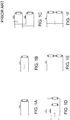
- FIGs. 1A-1F illustrate some typical EM ballast circuit configurations for fluorescent tube lamps.
- FIG. 1A shows an uncompensated configuration which exhibits a large inductive current and a low power factor (PF).
- FIG. 1B shows a parallel compensated configuration which uses a capacitor at the input to improve PF.
- FIG. 1C shows a series compensated dual lamp configuration which employs a series capacitor for compensation, where the upper lamp has a leading current while the lower lamp has a lagging current such that the two lamps compensate for each other, resulting in a total PF is close to unity.
- FIG. 1D shows a parallel compensated dual lamp configuration.
- FIG. 1E shows an uncompensated two-lamps-in-series configuration
- FIG. 1F shows a parallel compensated two-lamps-in-series configuration.
- the configurations of FIGs. 1A-1F illustrate inductive ballasts, with the exception of the upper lamp in FIG. 1C which illustrates a capacitive ballast.
- Illumination devices based on semiconductor light sources such as light-emitting diodes (LEDs), offer a viable alternative to traditional fluorescent, HID, and incandescent lamps. Functional advantages and benefits of LEDs include high energy conversion and optical efficiency, durability, lower operating costs, and many others.
- TLED newer LED tube
- a conventional switching mode driver may operate behind an EM ballast when caution is taken in the circuit design, but it often leads to very poor power factor, and to unbalanced light output when two TLED lamps are in series.
- a TLED lamp may be driven with a switching mode power supply (SMPS), but conventional SMPS drivers lead to poor power factor when operated behind a parallel compensated EM ballast (e.g., FIGs. 1B and 1D ).
- SMPS switching mode power supply
- conventional SMPS drivers can not operate in series because it leads to flicker and/or unbalanced light output between the two series connected lamps.
- there are safety issues which much be addressed related to mains power.
- TLED lamp which can be retrofit into existing lighting fixtures compatibly with a variety of installed EM ballasts which are designed for fluorescent lamps.
- EM ballasts which are designed for fluorescent lamps.
- TLED lamp which can maintain a high power factor when used in a lighting fixture with a compensated EM ballast configuration.
- a TLED lamp which can be connected in a series configuration with another TLED lamp without an unacceptable level of flicker and/or unbalanced light output between the two series connected TLED lamps.
- TLED lamp that can provide safe operation in an aluminum tube based architecture.
- a TLED lamp as disclosed herein can maintain a high power factor when used in a lighting fixture with a compensated ballast configuration, can be connected in a series configuration with another TLED lamp without an unacceptable level of flicker and/or unbalanced light output between the two series connected TLED lamps, and can provide safe operation in an aluminum tube based architecture.
- an apparatus comprises a light emitting diode (LED) tube (TLED) lamp, the TLED lamp including: at least partially transparent tube having an electrical connector configured to be installed in a fluorescent light fixture; one or more light emitting diodes provided inside the tube; and a lighting driver provided inside the tube and connected to the electrical connector and being configured to supply power to the one or more light emitting diodes.
- the lighting driver comprises a shunt switch circuit and a switching mode power supply.
- the shunt switch circuit comprises: a rectifier connected to the electrical connector, a shunt switching device connected across an output of the rectifier, an output capacitor and a diode connected in series across the output of the rectifier, wherein the capacitor is connected across an output of the shunt switch circuit, a voltage sensor configured to sense a bus voltage across the output capacitor, a current sensor configured to sense a rectifier current through the rectifier, and a processor configured to control a switching operation of the shunt switching device in response to the sensed bus voltage and the rectifier current.
- the switching mode power supply is configured to receive the bus voltage and in response thereto to supply a lamp current to drive the one or more light emitting diodes, and is further configured to provide galvanic isolation between the shunt switch circuit and the one or more light emitting diodes.
- the processor is configured to execute an algorithm to detect when an input of the rectifier is connected to mains power without an electromagnetic (EM) ballast, and in response thereto to disable the lighting driver
- EM electromagnetic
- the algorithm for detecting when the input of the rectifier is connected to mains power without an EM ballast includes disabling the supply of the lamp current to drive the one or more light emitting diodes; and while the supply of the lamp current is disabled, determining at least one of: (1) a peak rectifier current, and (2) a time delay between a zero crossing of the rectifier current and the peak rectifier current; and comparing at least one of: (1) the peak rectifier current and a peak detection threshold; and (2) the time delay and a time delay threshold to obtain a comparison result; and determining when the input of the rectifier is connected to mains power without the EM ballast based on the obtained comparison result.
- the processor is configured to execute an algorithm
- the processor is configured to execute an algorithm to detect a type of electromagnetic (EM) ballast connected to an input of the rectifier, and to control a switching operation of the shunt switching device to regulate the bus voltage according to the detected type of EM ballast.
- EM electromagnetic
- the processor controls the shunt switch to be turned on at a zero crossing of the rectifier current, and when the detected type of EM ballast is an inductive ballast, the processor controls the shunt switch to be turned off at a zero crossing of the rectifier current.
- the algorithm for detecting the type of EM ballast includes: controlling the shunt switch to be turned off at a zero crossing of the rectifier current and measuring a first average value of the rectifier current; controlling the shunt switch to be turned off at an offset time period with respect to the zero crossing of the rectifier current and measuring a second average value of the rectifier current; comparing the first average current to the second average current; when the second average current is less than the first average current, determining that the type of EM ballast is a capacitive ballast; and when the second average current is not less than the first average current, determining that the type of EM ballast is an inductive ballast.
- a device comprises a lighting driver, including: a shunt switch circuit configured to detect when an input of the lighting driver is connected to mains power without a ballast, and in response thereto to disable the lighting driver, and further configured to detect a type of ballast connected to the input of the lighting driver when the input of the lighting driver is connected to the ballast, and to regulate a bus voltage of the shunt switch circuit according to the detected type of ballast; and a switching mode power supply configured to receive the bus voltage of the shunt switch circuit and in response thereto to supply a lamp current to drive one or more light emitting diodes.
- a device in yet another aspect, includes: a rectifier connected to an input of the device, a shunt switching device connected across an output of the rectifier, an output capacitor and a diode connected in series across the output of the rectifier, wherein the output capacitor is connected across an output of the shunt switch circuit, a voltage sensor configured to sense a bus voltage across the output capacitor, a current sensor configured to sense a rectifier current through the rectifier, and a processor configured to control a switching operation of the shunt switching device in response to the sensed bus voltage and the rectifier current and further configured to execute an algorithm to detect when an input of the device is connected to mains power without an electromagnetic (EM) ballast.
- EM electromagnetic
- the term "LED” should be understood to include any electroluminescent diode or other type of carrier injection/junction-based system that is capable of generating radiation in response to an electric signal.
- the term LED includes, but is not limited to, various semiconductor-based structures that emit light in response to current, light emitting polymers, organic light emitting diodes (OLEDs), electroluminescent strips, and the like.
- the term LED refers to light emitting diodes of all types (including semi-conductor and organic light emitting diodes) that may be configured to generate radiation in one or more of the infrared spectrum, ultraviolet spectrum, and various portions of the visible spectrum (generally including radiation wavelengths from approximately 400 nanometers to approximately 700 nanometers).
- an LED configured to generate essentially white light may include a number of dies which respectively emit different spectra of electroluminescence that, in combination, mix to form essentially white light.
- a white light LED may be associated with a phosphor material that converts electroluminescence having a first spectrum to a different second spectrum.
- electroluminescence having a relatively short wavelength and narrow bandwidth spectrum "pumps" the phosphor material, which in turn radiates longer wavelength radiation having a somewhat broader spectrum.
- an LED does not limit the physical and/or electrical package type of an LED.
- an LED may refer to a single light emitting device having multiple dies that are configured to respectively emit different spectra of radiation (e.g., that may or may not be individually controllable).
- an LED may be associated with a phosphor that is considered as an integral part of the LED (e.g., some types of white LEDs).
- the term LED may refer to packaged LEDs, non-packaged LEDs, surface mount LEDs, chip-on-board LEDs, T-package mount LEDs, radial package LEDs, power package LEDs, LEDs including some type of encasement and/or optical element (e.g., a diffusing lens), etc.
- light source should be understood to refer to any one or more of a variety of radiation sources, including, but not limited to, LED-based sources (including one or more LEDs as defined above.
- a given light source may be configured to generate electromagnetic radiation within the visible spectrum, outside the visible spectrum, or a combination of both.
- light and “radiation” are used interchangeably herein.
- a light source may include as an integral component one or more filters (e.g., color filters), lenses, or other optical components.
- filters e.g., color filters
- lenses e.g., or other optical components.
- light sources may be configured for a variety of applications, including, but not limited to, indication, display, and/or illumination.
- an “illumination source” is a light source that is particularly configured to generate radiation having a sufficient intensity to effectively illuminate an interior or exterior space.
- “sufficient intensity” refers to sufficient radiant power in the visible spectrum generated in the space or environment (the unit “lumens” often is employed to represent the total light output from a light source in all directions, in terms of radiant power or "luminous flux”) to provide ambient illumination (i.e., light that may be perceived indirectly and that may be, for example, reflected off of one or more of a variety of intervening surfaces before being perceived in whole or in part).
- lighting unit is used herein to refer to an apparatus including one or more light sources of same or different types.
- a given lighting unit may have any one of a variety of mounting arrangements for the light source(s), enclosure/housing arrangements and shapes, and/or electrical and mechanical connection configurations. Additionally, a given lighting unit optionally may be associated with (e.g., include, be coupled to and/or packaged together with) various other components (e.g., control circuitry) relating to the operation of the light source(s).
- An "LED-based lighting unit” refers to a lighting unit that includes one or more LED-based light sources as discussed above, alone or in combination with other non LED-based light sources.
- lamp should be interpreted to refer to a lighting unit that includes connector(s) for receiving electrical power and for generating radiation (e.g., visible light) from the received electrical power.
- Examples include bulbs and tubes, including incandescent bulbs, fluorescent bulbs, fluorescent tubes, LED bulbs, LED tube (TLED) lamps, etc.
- lighting fixture is used herein to refer to an implementation or arrangement of one or more lighting units in a particular form factor, assembly, or package, and may be associated with (e.g., include, be coupled to and/or packaged together with) other components, for example an electromagnetic (EM) ballast, in particular for supplying power.
- EM electromagnetic
- controller is used herein generally to describe various apparatus relating to the operation of one or more light sources.
- a controller can be implemented in numerous ways (e.g., such as with dedicated hardware) to perform various functions discussed herein.
- a "processor” is one example of a controller which employs one or more microprocessors that may be programmed using software (e.g., microcode) to perform various functions discussed herein.
- a controller may be implemented with or without employing a processor, and also may be implemented as a combination of dedicated hardware to perform some functions and a processor (e.g., one or more programmed microprocessors and associated circuitry) to perform other functions. Examples of controller components that may be employed in various embodiments of the present disclosure include, but are not limited to, conventional microprocessors, application specific integrated circuits (ASICs), and field-programmable gate arrays (FPGAs).
- ASICs application specific integrated circuits
- FPGAs field-programmable gate arrays
- galvanic isolation refers to the principle of isolating functional sections of electrical systems preventing the moving of charge-carrying particles from one section to another. There is no electric current flowing directly from a first section to a second section when the first and second sections are galvanically isolated from each other. Energy and/or information can still be exchanged between the sections by other means, e.g. capacitance, induction, electromagnetic waves, optical, acoustic, or mechanical means.
- an “optocoupler” is an electronic device designed to transfer electrical signals by utilizing light waves to provide coupling with electrical isolation between its input and output, and may sometimes also be referred to as an opto-isolator, photocoupler, or optical isolator.
- mains refers to the general-purpose alternating current (AC) electric power supply from the public utility grid, and may sometimes also be referred to as household power, household electricity, domestic power, wall power, line power, city power, street power, and grid power.
- AC alternating current
- a processor or controller may be associated with one or more storage media (generically referred to herein as "memory,” e.g., volatile and non-volatile computer memory such as RAM, PROM, EPROM, and EEPROM, floppy disks, compact disks, optical disks, magnetic tape, etc.).
- the storage media may be encoded with one or more programs that, when executed on one or more processors and/or controllers, perform at least some of the functions discussed herein.
- Various storage media may be fixed within a processor or controller or may be transportable, such that the one or more programs stored thereon can be loaded into a processor or controller so as to implement various aspects of the present invention discussed herein.
- program or “computer program” are used herein in a generic sense to refer to any type of computer code (e.g., software or microcode) that can be employed to program one or more processors or controllers.
- Applicants have recognized and appreciated that it would be beneficial to provide a light emitting diode (LED) tube (TLED) lamp that can be retrofit into an existing lighting fixture for a fluorescent tube lamp with a compensated ballast configuration, and which can maintain a high power factor, can be connected in a series configuration with another TLED without an unacceptable level of flicker and/or unbalanced light output between the two series connected TLED lamps, and can provide safe operation in an aluminum tube based architecture.
- LED light emitting diode
- TLED light emitting diode
- various embodiments and implementations of the present invention are directed to a lighting driver that detects when it is connected to mains power without a ballast, and in response thereto disables the lighting driver, and further detects a type of ballast when it is connected to a ballast, and regulates an output bus voltage in response to the detected type of ballast.
- a switching mode power supply may be configured to receive the bus voltage and in response thereto to supply a current to drive one or more light emitting diodes.
- FIG. 2 illustrates an exemplary embodiment of a light emitting diode (LED) tube (TLED) lamp 30 that may be retrofit in place of a fluorescent tube lamp in an existing lighting fixture.
- TLED lamp 30 includes a substantially cylindrical shell or tube 32 and two end caps 34 each having a connector 35 provided therewith, and further includes a lighting driver 36 and one or more light emitting diodes (LEDs) 38.
- the tube 32 is at least partially transparent or translucent to visible light.
- LED lamp 30 may have only one end cap 34 and/or connector 35.
- Connector(s) 35 of TLED 30 are connected via connector(s) 20 to an electromagnetic (EM) ballast 10 that supplies TLED 30 with power from mains 12.
- EM electromagnetic
- lighting driver 36 receives power from ballast 10 via electrical connector(s) 35, and is configured to supply power to the one or more light emitting diodes 38.
- EM ballast 10 may be an uncompensated ballast, an inductive ballast, or a capacitive ballast.
- substantially cylindrical shell or tube 32 is metallic, for example aluminum, in which case TLED lamp 30 may be said to have an aluminum tube-based architecture.
- substantially cylindrical shell or tube 32 is made of glass, in which case TLED lamp 30 may be said to have a glass tube-based architecture.
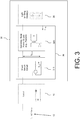
- FIG. 3 is a block diagram illustrating one exemplary embodiment of TLED lamp 30 supplied with power by EM ballast 10.
- TLED lamp 30 includes a lighting driver 36 and one or more LEDs 38.
- Lighting driver 36 has a dual stage topology and includes a shunt switch circuit 310 and a switching mode power supply (SMPS) 320.
- SMPS switching mode power supply
- EM ballast 10 may be an uncompensated ballast, an inductive ballast, or a capacitive ballast.
- shunt switch circuit 310 provides compatibility with EM ballast 10, while the SMPS provides mains isolation.
- shunt switch circuit 310 is configured to detect when an input of lighting driver 36 is connected to mains power 12 without ballast 10, and in response thereto to disable lighting driver 36, and further configured to detect a type of ballast 10 connected to the input of lighting driver 36 when the input of lighting driver 36 is connected to ballast 10, and to regulate a bus voltage (V BUS ) of shunt switch circuit 310 according to the detected type of ballast 10.
- V BUS bus voltage
- shunt switch circuit 310 may include an over-current protection circuit.
- SMPS 320 is configured to receive the bus voltage V BUS and in response thereto to supply a lamp current I LED to drive the one or more light emitting diodes 38.
- SMPS comprises a flyback circuit.
- shunt switch circuit 310 is controlled is such a way that the bus voltage V BUS is regulated.
- V BUS is regulated to be about 150V.
- SMPS 320 e.g., a flyback stage
- SMPS delivers about 25W to the one or more LEDs 38.
- FIG. 4 is a detailed diagram illustrating one exemplary embodiment of a TLED lamp 400 supplied with power by an electromagnetic (EM) ballast 10, which may be an uncompensated ballast, an inductive ballast, or a capacitive ballast.
- TLED lamp 400 is one embodiment of TLED 30 of FIGs. 2 and 3 .
- TLED lamp 400 includes: a lighting driver comprising a shunt switch circuit 410 and a switching mode power supply (SMPS) 420; and one or more LEDs 38.
- Shunt switch circuit 410 is one embodiment of shunt switch circuit 310 of FIG. 3
- SMPS 420 is one embodiment of SMPS 320 of FIG. 3 .
- Shunt switch circuit 410 comprises: a rectifier 411;, a shunt switching device 412 connected across an output of rectifier 411; an output capacitor 413 and a diode 414 connected in series across the output of rectifier 411, wherein output capacitor 413 is connected across an output of shunt switch circuit 410; a gate driver 415 for driving shunt switching device 412; a voltage sensor 416 configured to sense a bus voltage V BUS across output capacitor 413; a current sensor 417 configured to sense a rectifier current through rectifier 411; a processor 418 configured to control a switching operation of shunt switching device 412 in response to the sensed bus voltage V BUS and the rectifier current; and a protection circuit 419 for protecting ballast 10 and/or the lighting driver of TLED lamp 400 from a short circuit and/or over-voltage and/or over-current condition under control of processor 418.
- Processor 418 may include one of more associated memory devices, include volatile memory (e.g., dynamic random access memory) and/or nonvolatile memory (e.g., FLASH memory) for storing programming code (i.e. software) for various operations which may be performed by processor 418.
- volatile memory e.g., dynamic random access memory
- nonvolatile memory e.g., FLASH memory
- programming code i.e. software
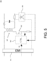
- FIG. 5 is a block diagram illustrating one exemplary embodiment of switching mode power supply (SMPS) 420.
- SMPS 420 includes an electromagnetic interference (EMI) barrier 510; an isolation transformer 520 that provides galvanic isolation between the bus voltage V BUS and the lamp current I LED ; a switch 530 in series with a primary winding of isolation transformer 520; a controller 540 configured to control switch 530 to control a duty cycle of the lamp current I LED ; and an optical coupler 550 that provides to controller 540 a feedback signal based on the lamp current I LED .
- Optical coupler 550 provides galvanic isolation between light emitting diodes 38 and controller 540.
- controller 540 receives an enable signal (also shown in FIG. 4 ) from processor 418 of shunt switch circuit 410 which selectively enables and disables operation of SMPS 420. This feature may be used in connection with ballast type detection and detection of abnormal operating situations, as described below.
- processor 418 manages the timing control of shunt switching device 412 and regulates the bus voltage V BUS , for example with a digital proportional integrator (PI) type compensation loop as described in greater detail below with respect to FIG. 11 .
- processor 418 controls the duration of a switching control pulse supplied by gate driver 415 to shunt switching device 412 and its position with respect to zero crossings of the rectifier current as sensed by current sensor 417.
- processor 418 is configured to execute an algorithm to detect when an input of rectifier 411 is connected to mains power 12 without EM ballast 10, and in response thereto to disable the lighting driver, including shunt switch circuit 410 and/or SMPS 420.
- processor 418 is configured to execute an algorithm to detect the type of EM ballast 10 connected to the input of rectifier 411 (e.g., a capacitive ballast or an inductive ballast), and to control the switching operation of shunt switching device 412 to regulate the bus voltage V BUS according to the detected type of EM ballast 10.
- rectifier 411 e.g., a capacitive ballast or an inductive ballast
- shunt switching device 412 to regulate the bus voltage V BUS according to the detected type of EM ballast 10.
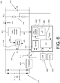
- FIG. 6 is a schematic diagram illustrating one exemplary embodiment of shunt switch circuit 410.
- voltage sensor 416 comprises a resistive voltage divider, with the impedance of the resistors being much greater than that of capacitor C2 at the switching frequency of shunt switching device 412.
- current sensor 417 comprises a sampling resistor R S .
- a low voltage supply 610 which, for example, may be derived from an auxiliary winding of a power transformer in SMPS 420.
- Low voltage supply 610 supplies the voltages for gate driver 415 and processor 418.
- processor 418 includes an operational amplifier (op amp) 620, a zero crossing detector 630, a microprocessor or microcontroller 640, and an analog-to-digital converter (ADC) 650.
- Zero crossing detector 630 may include a comparator.
- Shunt switch circuit 410 also includes low pass filter (LPF) 660 and negative temperature compensation (NTC) sensor 670.
- LPF low pass filter
- NTC negative temperature compensation
- voltage sensor 416 senses the bus voltage V BUS and supplies the sensed voltage V SENSE to processor 418. Also, current sensor 417 supplies the measured rectifier current to op amp 620. The amplified rectifier current from op amp 620 is supplied to zero crossing detector 630 for zero crossing detection, and is also supplied to LPF 660. Zero crossing detector 630 detects when the rectifier current experiences a zero crossing. LPF 660 averages the rectifier current and supplies the averaged rectifier current I AVG to the input of ADC 650 which converts it to a digital value.
- Processor 418 may use the sensed bus voltage V BUS , the rectifier current, and the averaged rectifier current I AVG to execute various algorithms to regulate the bus voltage V BUS , to detect a type of ballast 10 to with TLED lamp 400 is connected, and to detect when TLED lamp 400 is connected to mains 12 without a ballast, as will be explained in greater detail below with respect to FIGs 7A-B through FIGs. 12A-B .
- FIG. 7A illustrates a relationship between various signals which may be employed by shunt switch circuit 410 when operating in a first operating mode.
- FIG. 7A illustrates a relationship between the rectifier current and switching control pulses supplied to shunt switching device 412 by processor 418 via gate driver 415 when shunt switch circuit 410 operates in a leading edge (LE) control mode.
- LE leading edge
- shunt switching device 412 is controlled by processor 418 to be turned off at zero-crossings of the rectifier current.
- the duration of the "OFF" time of shunt switching device 412 in each period of the rectifier current determines the level of the bus voltage V BUS .
- processor 418 may regulate the bus voltage V BUS .
- PI proportional integrator
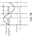
- FIG. 7B illustrates a relationship between various signals which may be employed by shunt switch circuit 420 when operating in a second operating mode.
- FIG. 7B illustrates a relationship between the rectifier current and switching control pulses supplied to shunt switching device 412 by processor 418 via gate driver 415 when shunt switch circuit 410 operates in a trailing edge (TE) control mode.
- TE trailing edge
- the loss in the EM ballast is high when a TLED lamp is connected to a capacitive ballast and operated in the LE control mode, thus causing a risk of overheating when operated with certain ballasts.
- the loss is greatly reduced.
- TLED lamp 400 may employ trailing edge (TE) control when TLED lamp 400 is connected to a capacitive ballast, and may employ leading edge (LE) control when TLED lamp 400 is connected to an inductive ballast.
- TE trailing edge
- LE leading edge
- TLED lamp 400 and in particular shunt switch circuit 410, and even more particularly processor 418, may employ a ballast type detection algorithm to determine whether TLED lamp 400 is connected to a capacitive ballast or an inductive ballast so that an appropriate control mode can be applied.
- FIGs. 8A-B plot average rectifier current versus switching control pulse timing for an exemplary embodiment of a TLED lamp and as associated lighting driver connected to two different types of electromagnetic ballasts.
- FIG. 8A illustrates a case where the TLED lamp and associated lighting driver are connected to a capacitive ballast
- FIG. 8B illustrates a case where the TLED lamp and associated lighting driver are connected to an inductive ballast.
- FIGs. 8A-B plot the variation of the average rectifier current when the switching control pulse is shifted across half of one period of the mains power.
- the mains frequency is 50 Hz, yielding a total shift of 10ms plotted in steps of 0.5ms.
- the average rectifier current I AVG is minimal when operated at the TE control point
- the average rectifier current I AVG is minimal when operated at the LE control point.
- FIGs. 8A-B it can be seen that by measuring the average rectifier current I AVG at the normal LE switching point, and then measuring the average rectifier current I AVG-SHIFTED when the timing of the switching control pulse is shifted by about 2ms (to provide adequate margin for noise, mains voltage variation, etc.) with respect to the normal LE switching point, and then comparing I AVG to I AVG-SHIFTED , it is possible to detect whether the ballast is a capacitive ballast or an inductive ballast. Specifically, if the average rectifier current I AVG-SHIFTED when the timing of the switching control pulse is shifted with respect to the normal LE switching point is less than the average rectifier current I AVG at the normal LE switching point, then the response is following FIG.
- ballast is a capacitive ballast. Conversely, if the shifted average rectifier current I AVG-SHIFTED is greater than the average rectifier current I AVG , then the response is following FIG. 8B and it can be concluded that the ballast is an inductive ballast.
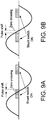
- FIGs. 9A-B illustrate two embodiments of a method of detecting a type of ballast connected to a TLED lamp and associated lighting driver.
- the timing of the switching control pulse is shifted by delaying the switching control pulse with respect to the normal LE switching point.
- the timing of the switching control pulse is shifted by advancing the switching control pulse with respect to the normal LE switching point.
- FIG. 10 is a flowchart of one embodiment of a method 1000 of detecting a type of ballast connected to a TLED lamp and associated lighting driver. As one particular example, the method 1000 will be described with respect to the TLED lamp 400 of FIG. 4 .
- TLED lamp 400 is operated with leading edge (LE) control. More specifically, processor 418 regulates the bus voltage V BUS with LE control of the switching control pulse provided to shunt switching device 412 by gate driver 415. It is beneficial that the method 1000 begins with LE control, since this is a safe control method for both inductive and capacitive ballasts with no excessive ballast loss, while trailing edge (TE) control may lead to unacceptable loss for inductive ballasts and therefore present a risk of overheating.
- LE leading edge
- processor 418 regulates the bus voltage V BUS for a given period until the lamp power stabilizes, and then records the measured average rectifier current I AVG .
- processor 418 shifts the switching control pulse by a predetermined time shift, for example, 2ms.
- the time shift is selected such that the average rectifier current will have a significant difference between the LE switching point and the shifted switching point, while at the same time not leading to excessive loss for the shifted pulse operation.
- processor 418 again regulates the bus voltage V BUS for a given period until the lamp power stabilizes, and then records the measured average rectifier current I AVG-SHIFTED .
- processor 418 compares the average rectifier current I AVG at the normal LE switching point to the average rectifier current I AVG-SHIFTED when the timing of the switching control pulse is shifted with respect to the normal LE switching point.
- processor 418 determines that the ballast is a capacitive ballast and processor 418 operates shunt switch circuit 410 and TLED lamp 400 with TE control. Otherwise processor 418 determines that the ballast is an inductive ballast and processor 418 operates shunt switch circuit 410 and TLED lamp 400 with LE control. As a result, TLED lamp 400 is automatically operated with minimum EM ballast loss for different fixture circuits.
- FIG. 11 is a functional block diagram illustrating operation of a feedback loop 1100 for setting a bus voltage for a shunt switch circuit.
- FIG. 11 illustrates operation of a proportional integrator (PI) loop.
- Feedback loop 1100 includes an adder 1110, a gain block (PI compensator) 1120, a modulator 1130, a pulse shifter 1140, a shunt switch 1150, and a feedback gain block 1160.
- TLED lamp 400 is configured to be retrofit into an existing lighting fixture having a ballast whose type may not be known. However, it may occur that TLED lamp 400 is misused and is connected directly to mains power 12 without any EM ballast. In that case, beneficially processor 418 may execute an algorithm to detect when an input of rectifier 411, and therefore of TLED lamp 400, is connected to mains power 12 without an electromagnetic (EM) ballast, and in response thereto to disable the lighting driver.
- EM electromagnetic
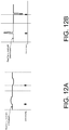
- FIGs. 12A-B illustrate rectifier current signals when one exemplary embodiment of a TLED lamp (e.g., TLED lamp 400) is connected, respectively, to an EM ballast ( FIG. 12A ), and to mains power 12 without an EM ballast ( FIG. 12B ). Because of much lower source impedance when rectifier 411 is connected to mains power 12 without an EM ballast, the rectifier current has a much higher peak as shown in FIG. 12B , compared to FIG. 12A . Also as shown in FIG. 12B , when rectifier 411 is connected to mains power 12 without an EM ballast, then the zero-crossing of the rectifier current is located closer in time to the peak of the rectifier current.
- a TLED lamp e.g., TLED lamp 400
- TLED lamp 400 By monitoring the peak rectifier current and/or the time delay between a zero crossing of the rectifier current and the peak rectifier current, misuse of TLED lamp 400 by direct connection to mains power 12 can be detected. Beneficially, when the absence of a ballast is detected, then the lighting driver is disabled to protect TLED lamp 400. Beneficially, SMPS 420 is disabled while detecting whether or not the input of rectifier 411 is connect to mains power 12 without a ballast.
- FIG. 13 is a detailed diagram illustrating another exemplary embodiment of a TLED lamp 1300 supplied with power by an electromagnetic (EM) ballast 10.
- TLED lamp 1300 is the same as TLED lamp 400, except that TLED lamp 1300 employs a non-isolated SMPS 1320.
- TLED lamp 1300 may have a glass-tube based architecture that does not require mains power isolation in the lighting driver. In that case, when the LED string voltage does not match the optimal output voltage of shunt switch circuit 410, then SMPS driver 1330 converts the bus voltage V BUS to match the LED string voltage.
- the benefit of using a non-isolated SMPS 1320 is the lower cost and smaller size achieved by removal of the isolation requirement.
- the SMPS driver can be left out altogether and the shunt switch stage may then regulate the LED current instead of the bus voltage.
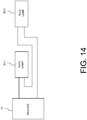
- FIG. 14 illustrates two TLEDs 30-1 and 30-1 connected in series with an EM ballast 100.
- Inventive embodiments of the present disclosure are directed to each individual feature, system, article, material, kit, and/or method described herein.
Landscapes
- Circuit Arrangement For Electric Light Sources In General (AREA)
Applications Claiming Priority (2)
| Application Number | Priority Date | Filing Date | Title |
|---|---|---|---|
| US201161443300P | 2011-02-16 | 2011-02-16 | |
| PCT/IB2012/050705 WO2012110973A1 (en) | 2011-02-16 | 2012-02-16 | Electromagnetic ballast-compatible lighting driver for light-emitting diode lamp |
Publications (2)
| Publication Number | Publication Date |
|---|---|
| EP2676526A1 EP2676526A1 (en) | 2013-12-25 |
| EP2676526B1 true EP2676526B1 (en) | 2019-05-08 |
Family
ID=45815920
Family Applications (1)
| Application Number | Title | Priority Date | Filing Date |
|---|---|---|---|
| EP12708395.4A Active EP2676526B1 (en) | 2011-02-16 | 2012-02-16 | Electromagnetic ballast-compatible lighting driver for light-emitting diode lamp |
Country Status (7)
| Country | Link |
|---|---|
| US (1) | US20130320869A1 (enExample) |
| EP (1) | EP2676526B1 (enExample) |
| JP (1) | JP2014509053A (enExample) |
| CN (1) | CN103380658A (enExample) |
| RU (1) | RU2013142062A (enExample) |
| TW (1) | TW201240517A (enExample) |
| WO (1) | WO2012110973A1 (enExample) |
Families Citing this family (77)
| Publication number | Priority date | Publication date | Assignee | Title |
|---|---|---|---|---|
| US9497821B2 (en) | 2005-08-08 | 2016-11-15 | Jiaxing Super Lighting Electric Appliance Co., Ltd | LED tube lamp |
| US9794990B2 (en) | 2014-09-28 | 2017-10-17 | Jiaxing Super Lighting Electric Appliance Co., Ltd. | LED tube lamp with improved compatibility with an electrical ballast |
| US10021742B2 (en) | 2014-09-28 | 2018-07-10 | Jiaxing Super Lighting Electric Appliance Co., Ltd | LED tube lamp |
| US11131431B2 (en) | 2014-09-28 | 2021-09-28 | Jiaxing Super Lighting Electric Appliance Co., Ltd | LED tube lamp |
| US9480109B2 (en) | 2014-10-14 | 2016-10-25 | Jiaxing Super Lighting Electric Appliance Co., Lti | Power source module for LED lamp |
| US9781805B2 (en) | 2015-03-10 | 2017-10-03 | Jiaxing Super Lighting Electric Appliance Co., Ltd. | LED tube lamp |
| US9871404B2 (en) | 2011-12-12 | 2018-01-16 | Cree, Inc. | Emergency lighting devices with LED strings |
| US10117295B2 (en) | 2013-01-24 | 2018-10-30 | Cree, Inc. | LED lighting apparatus for use with AC-output lighting ballasts |
| US9445465B2 (en) * | 2012-03-29 | 2016-09-13 | Koninklike Philips N.V. | Adaptation circuit for coupling LED to ballast |
| KR101382226B1 (ko) * | 2012-04-20 | 2014-04-10 | 주식회사 하이딥 | 형광등용 안정기를 이용한 led 조명 장치 |
| US9826595B2 (en) * | 2012-06-15 | 2017-11-21 | Aleddra Inc. | Linear solid-state lighting with electric shock current sensing |
| KR101635798B1 (ko) * | 2012-08-29 | 2016-07-04 | 한국과학기술원 | 병렬형 엘. 이. 디. 조명장치 |
| US9204504B2 (en) * | 2012-09-17 | 2015-12-01 | Energy Focus, Inc. | LED lamp system |
| US10045406B2 (en) | 2013-01-24 | 2018-08-07 | Cree, Inc. | Solid-state lighting apparatus for use with fluorescent ballasts |
| US9439249B2 (en) * | 2013-01-24 | 2016-09-06 | Cree, Inc. | LED lighting apparatus for use with AC-output lighting ballasts |
| US10104723B2 (en) | 2013-01-24 | 2018-10-16 | Cree, Inc. | Solid-state lighting apparatus with filament imitation for use with florescent ballasts |
| CN105265017B (zh) * | 2013-03-11 | 2017-09-08 | 飞利浦照明控股有限公司 | 使用补偿电流控制的供电电流变化的减小 |
| CN105247957B (zh) | 2013-03-14 | 2017-08-25 | 飞利浦照明控股有限公司 | 用于改进led灯具的性能和一致性的电流反馈 |
| DE102013205189A1 (de) * | 2013-03-25 | 2014-09-25 | The Green Monkeys Holdings, Ltd. | Elektronisches Bauteil und LED-Leuchtmittel |
| DE102013207701B4 (de) * | 2013-04-26 | 2025-05-22 | Tridonic Gmbh & Co Kg | Konverter-Modul für Leuchtmittel mit Lasterkennungsfunktion und Verfahren zum Betrieb eines Konverter-Moduls für Leuchtmittel mit Lasterkennungsfunktion |
| WO2014195350A1 (en) * | 2013-06-04 | 2014-12-11 | Koninklijke Philips N.V. | Led lamp comprising a safety module for safe operation on various ballasts |
| ES2602309T3 (es) | 2013-06-27 | 2017-02-20 | Philips Lighting Holding B.V. | Tubo de diodo emisor de luz modernizado |
| WO2015014680A1 (en) | 2013-07-30 | 2015-02-05 | Koninklijke Philips N.V. | Led replacement lamp for safe operation under fault condition |
| EP2922369A1 (en) * | 2014-03-18 | 2015-09-23 | Laurence P. Sadwick | Fluorescent lamp LED replacement |
| US10098199B2 (en) * | 2014-08-13 | 2018-10-09 | Lumenetix, Inc. | Architectures for light emitting diode (LED) lighting systems |
| US9049765B1 (en) | 2014-09-04 | 2015-06-02 | Colorado Energy Research Technologies, LLC | Systems and methods for converting alternating current to drive light-emitting diodes |
| US11480305B2 (en) | 2014-09-25 | 2022-10-25 | Jiaxing Super Lighting Electric Appliance Co., Ltd. | LED tube lamp |
| US9795001B2 (en) | 2014-09-28 | 2017-10-17 | Jiaxing Super Lighting Electric Appliance Co., Ltd. | LED tube lamp with overcurrent and/or overvoltage protection capabilities |
| US9775215B2 (en) | 2014-09-28 | 2017-09-26 | Jiaxing Super Lighting Electric Appliance Co., Ltd. | LED tube lamp with operating modes compatible with electrical ballasts |
| US9689536B2 (en) | 2015-03-10 | 2017-06-27 | Jiaxing Super Lighting Electric Appliance Co., Ltd. | LED tube lamp |
| US9756698B2 (en) * | 2014-09-28 | 2017-09-05 | Jiaxing Super Lighting Electric Appliance Co., Ltd. | LED tube lamp with two operating modes compatible with electrical ballasts |
| US10054271B2 (en) | 2015-03-10 | 2018-08-21 | Jiaxing Super Lighting Electric Appliance Co., Ltd. | LED tube lamp |
| US10560989B2 (en) | 2014-09-28 | 2020-02-11 | Jiaxing Super Lighting Electric Appliance Co., Ltd | LED tube lamp |
| CN105472836B (zh) | 2014-09-28 | 2023-12-19 | 嘉兴山蒲照明电器有限公司 | Led直管灯 |
| US9526145B2 (en) * | 2014-09-28 | 2016-12-20 | Jiaxing Super Lighting Electric Appliance Co., Lti | LED tube lamp |
| US10208898B2 (en) | 2015-04-29 | 2019-02-19 | Jiaxing Super Lighting Electric Appliance Co., Ltd. | LED tube lamp with operating modes compatible with electrical ballasts |
| US10845008B2 (en) | 2014-09-28 | 2020-11-24 | Zhejiang Super Lighting Electric Appliance Co., Ltd. | LED filament and LED light bulb |
| WO2016058177A1 (en) * | 2014-10-17 | 2016-04-21 | James Lighting Group Co., Limited | Ballast-compatible lighting driver and light emitting diode lamp comprising the same |
| US9894732B2 (en) | 2014-10-17 | 2018-02-13 | Jiaxing Super Lighting Electric Appliance Co., Ltd. | LED tube lamp compatible with different sources of external driving signal |
| JP2017538252A (ja) * | 2014-10-27 | 2017-12-21 | フィリップス ライティング ホールディング ビー ヴィ | ワイヤレスled管形ランプデバイス |
| US10514134B2 (en) | 2014-12-05 | 2019-12-24 | Jiaxing Super Lighting Electric Appliance Co., Ltd | LED tube lamp |
| US9419537B1 (en) * | 2015-01-29 | 2016-08-16 | Technical Consumer Products, Inc. | Light emitting diode (LED) driver having direct replacement capabilities |
| US9826585B2 (en) | 2015-03-10 | 2017-11-21 | Jiaxing Super Lighting Electric Appliance Co., Ltd. | LED tube lamp |
| US9867239B2 (en) * | 2015-03-10 | 2018-01-09 | Jiaxing Super Lighting Electric Appliance Co., Ltd. | Light emiting diode (LED) tube lamp capable of adapting to different driving environments |
| US11028973B2 (en) | 2015-03-10 | 2021-06-08 | Jiaxing Super Lighting Electric Appliance Co., Ltd. | Led tube lamp |
| US9897265B2 (en) | 2015-03-10 | 2018-02-20 | Jiaxing Super Lighting Electric Appliance Co., Ltd. | LED tube lamp having LED light strip |
| US11519565B2 (en) | 2015-03-10 | 2022-12-06 | Jiaxing Super Lighting Electric Appliance Co., Ltd | LED lamp and its power source module |
| US10197225B2 (en) | 2015-03-10 | 2019-02-05 | Jiaxing Super Lighting Electric Appliance Co., Ltd. | LED tube lamp |
| US9903577B2 (en) | 2015-03-10 | 2018-02-27 | Jiaxing Super Lighting Electric Appliance Co., Ltd. | LED tube lamp including light strip including a pad and an opening formed on the pad |
| CN107432064A (zh) * | 2015-03-17 | 2017-12-01 | 飞利浦照明控股有限公司 | Led管灯 |
| US9750096B2 (en) | 2015-03-25 | 2017-08-29 | Jiaxing Super Lighting Electric Appliance Co., Ltd. | Dual-Mode LED tube lamp |
| EP3275289B1 (en) | 2015-03-26 | 2024-02-14 | Silicon Hill B.V. | Led lighting system |
| NL2014525B1 (en) * | 2015-03-26 | 2017-01-06 | Silicon Hill Bv | Led lighting system. |
| US9913336B2 (en) * | 2015-04-03 | 2018-03-06 | Jiaxing Super Lighting Electric Appliance Co., Ltd. | Light emiting diode (LED) tube lamp compatible with different ballasts providing external driving signal |
| US10070498B2 (en) | 2015-04-14 | 2018-09-04 | Jiaxing Super Lighting Electric Appliance Co., Ltd. | LED tube lamp with improved compatibility with electrical ballasts |
| US9841174B2 (en) | 2015-04-29 | 2017-12-12 | Jiaxing Super Lighting Electric Appliance Co., Ltd. | LED tube lamp |
| JP6547498B2 (ja) * | 2015-08-03 | 2019-07-24 | 株式会社リコー | 照明灯、照明装置及び点灯制御装置 |
| US11035526B2 (en) | 2015-12-09 | 2021-06-15 | Jiaxing Super Lighting Electric Appliance Co., Ltd. | LED tube lamp |
| CN105704867B (zh) * | 2016-04-26 | 2018-01-12 | 杰华特微电子(杭州)有限公司 | 电压控制电路、led驱动电路及其控制方法 |
| EP3566546B1 (en) | 2017-01-03 | 2020-08-05 | Signify Holding B.V. | A retrofit light emitting diode, led, tube for replacing a fluorescent tube |
| CN110121918B (zh) | 2017-01-04 | 2022-06-17 | 昕诺飞控股有限公司 | 照明设备和照明系统以及提供维护信息的方法 |
| JP2020513221A (ja) | 2017-03-08 | 2020-05-07 | シグニファイ ホールディング ビー ヴィSignify Holding B.V. | 電子安定器インターフェース回路 |
| TWI623243B (zh) * | 2017-05-26 | 2018-05-01 | 轉換式定電流led驅動器 | |
| EP3649832B1 (en) * | 2017-07-06 | 2020-12-23 | Signify Holding B.V. | Retrofit led lighting device for connection to a ballast and arranged to detect a dip in mains voltage using a zero current detector |
| CN207283866U (zh) * | 2017-07-18 | 2018-04-27 | 晨辉光宝科技有限公司 | Led直管灯 |
| EP3659397B1 (en) | 2017-07-25 | 2021-06-30 | Signify Holding B.V. | Tubular lighting device, luminaire and method for operating with an electronic ballast |
| US10986713B2 (en) | 2017-07-25 | 2021-04-20 | Signify Holding B.V. | Retrofit lamp and a lighting system using the same |
| CN107567130B (zh) * | 2017-08-21 | 2023-09-12 | 矽力杰半导体技术(杭州)有限公司 | 供电电路及应用其的led驱动电路 |
| JP6755431B1 (ja) * | 2017-08-24 | 2020-09-16 | シグニファイ ホールディング ビー ヴィSignify Holding B.V. | 光のちらつきのない安定したドライバ動作を向上させるための改善されたタイミングイベント検出を有するレトロフィットled照明デバイス |
| US10986712B2 (en) | 2017-09-30 | 2021-04-20 | Signify Holding B.V. | Controllable driver and drive method to connect an electronic ballast to an LED light source based on the model, type, or identity of the ballast |
| US11083058B2 (en) | 2018-01-02 | 2021-08-03 | Signify Holding B.V. | Lighting drive, lighting system and control method |
| EP3837923A1 (en) * | 2018-08-17 | 2021-06-23 | Signify Holding B.V. | A led driver and led lighting system for use with a high frequency electronic ballast |
| TWI643526B (zh) * | 2018-09-06 | 2018-12-01 | 峒鑫科技股份有限公司 | 發光二極體照明電路 |
| US10871280B2 (en) * | 2018-12-27 | 2020-12-22 | Shanghai Lumixess Lighting Technology Company | Connection terminal and illumination device |
| WO2020148259A1 (en) | 2019-01-16 | 2020-07-23 | Signify Holding B.V. | A power source type determiner |
| JP7348295B2 (ja) * | 2019-02-20 | 2023-09-20 | シグニファイ ホールディング ビー ヴィ | 高輝度放電ランプを交換するためのled照明ユニットのためのledドライバ |
| US11762447B2 (en) * | 2021-12-22 | 2023-09-19 | Schweitzer Engineering Laboratories, Inc. | Power supply with boost stage to improve ride through performance |
Family Cites Families (13)
| Publication number | Priority date | Publication date | Assignee | Title |
|---|---|---|---|---|
| US5296815A (en) * | 1992-07-14 | 1994-03-22 | Rensselaer Polytechnic Institute | Device for detecting the type of ballast of a discharge lamp |
| US7049761B2 (en) * | 2000-02-11 | 2006-05-23 | Altair Engineering, Inc. | Light tube and power supply circuit |
| US6445142B1 (en) * | 2001-05-08 | 2002-09-03 | Teldata Solutions Llc | Apparatus and method for remotely detecting a magnetic ballast |
| US6714429B2 (en) * | 2001-08-15 | 2004-03-30 | Astec International Limited | Active inrush current control for AC to DC converters |
| US6860628B2 (en) * | 2002-07-17 | 2005-03-01 | Jonas J. Robertson | LED replacement for fluorescent lighting |
| JP2006139755A (ja) * | 2004-10-15 | 2006-06-01 | Toshiba Lighting & Technology Corp | Led式標識灯点灯装置及び標識灯システム |
| US20060193131A1 (en) * | 2005-02-28 | 2006-08-31 | Mcgrath William R | Circuit devices which include light emitting diodes, assemblies which include such circuit devices, and methods for directly replacing fluorescent tubes |
| JP4678215B2 (ja) * | 2005-03-15 | 2011-04-27 | サンケン電気株式会社 | スイッチング電源装置 |
| CN101690396B (zh) * | 2007-06-27 | 2012-12-26 | 皇家飞利浦电子股份有限公司 | 用于向光源供应电压信号和电流信号的方法和设备 |
| US8502454B2 (en) * | 2008-02-08 | 2013-08-06 | Innosys, Inc | Solid state semiconductor LED replacement for fluorescent lamps |
| US8664880B2 (en) * | 2009-01-21 | 2014-03-04 | Ilumisys, Inc. | Ballast/line detection circuit for fluorescent replacement lamps |
| SE533502C2 (sv) * | 2009-07-29 | 2010-10-12 | Td Light Sweden Ab | Belysningssystem |
| CN101730347A (zh) * | 2009-12-31 | 2010-06-09 | 深圳市宝驰达实业有限公司 | 一种照明用led驱动电路 |
-
2012
- 2012-02-16 TW TW101105137A patent/TW201240517A/zh unknown
- 2012-02-16 WO PCT/IB2012/050705 patent/WO2012110973A1/en not_active Ceased
- 2012-02-16 EP EP12708395.4A patent/EP2676526B1/en active Active
- 2012-02-16 RU RU2013142062/07A patent/RU2013142062A/ru not_active Application Discontinuation
- 2012-02-16 CN CN2012800089368A patent/CN103380658A/zh active Pending
- 2012-02-16 US US13/985,150 patent/US20130320869A1/en not_active Abandoned
- 2012-02-16 JP JP2013554041A patent/JP2014509053A/ja active Pending
Non-Patent Citations (1)
| Title |
|---|
| None * |
Also Published As
| Publication number | Publication date |
|---|---|
| TW201240517A (en) | 2012-10-01 |
| WO2012110973A1 (en) | 2012-08-23 |
| CN103380658A (zh) | 2013-10-30 |
| US20130320869A1 (en) | 2013-12-05 |
| EP2676526A1 (en) | 2013-12-25 |
| RU2013142062A (ru) | 2015-03-27 |
| JP2014509053A (ja) | 2014-04-10 |
Similar Documents
| Publication | Publication Date | Title |
|---|---|---|
| EP2676526B1 (en) | Electromagnetic ballast-compatible lighting driver for light-emitting diode lamp | |
| US9485833B2 (en) | Method and apparatus for increasing dimming range of solid state lighting fixtures | |
| EP2737774B1 (en) | System and method for implementing mains-signal-based dimming of a solid state lighting module | |
| US9357600B2 (en) | Electronic ballast-compatible lighting driver for light-emitting diode lamp | |
| US10015860B2 (en) | Method and apparatus for detecting presence of dimmer and controlling power delivered to solid state lighting load | |
| CN102577606B (zh) | 提供固态照明系统的深度调光的方法和装置 | |
| US8816593B2 (en) | Method and apparatus selectively determining universal voltage input for solid state light fixtures | |
| US20120274216A1 (en) | Selectively activated rapid start/bleeder circuit for solid state lighting system | |
| EP2468076B1 (en) | Method and apparatus providing universal voltage input for solid state light fixtures | |
| US8975820B2 (en) | Smooth dimming of solid state light source using calculated slew rate | |
| WO2016184729A1 (en) | Deep dimming of lighting device with trailing edge phase-cut dimmer |
Legal Events
| Date | Code | Title | Description |
|---|---|---|---|
| PUAI | Public reference made under article 153(3) epc to a published international application that has entered the european phase |
Free format text: ORIGINAL CODE: 0009012 |
|
| 17P | Request for examination filed |
Effective date: 20130916 |
|
| AK | Designated contracting states |
Kind code of ref document: A1 Designated state(s): AL AT BE BG CH CY CZ DE DK EE ES FI FR GB GR HR HU IE IS IT LI LT LU LV MC MK MT NL NO PL PT RO RS SE SI SK SM TR |
|
| DAX | Request for extension of the european patent (deleted) | ||
| RAP1 | Party data changed (applicant data changed or rights of an application transferred) |
Owner name: PHILIPS LIGHTING HOLDING B.V. |
|
| STAA | Information on the status of an ep patent application or granted ep patent |
Free format text: STATUS: EXAMINATION IS IN PROGRESS |
|
| RIN1 | Information on inventor provided before grant (corrected) |
Inventor name: ZIJLSTRA, PATRICK, JOHN Inventor name: TAO, HAIMIN Inventor name: JANS, WILLIAM, PETER, MECHTILDIS, MARIE Inventor name: VAN BODEGRAVEN, TIJMEN, CORNELIS |
|
| 17Q | First examination report despatched |
Effective date: 20170712 |
|
| GRAP | Despatch of communication of intention to grant a patent |
Free format text: ORIGINAL CODE: EPIDOSNIGR1 |
|
| STAA | Information on the status of an ep patent application or granted ep patent |
Free format text: STATUS: GRANT OF PATENT IS INTENDED |
|
| RAP1 | Party data changed (applicant data changed or rights of an application transferred) |
Owner name: PHILIPS LIGHTING HOLDING B.V. |
|
| INTG | Intention to grant announced |
Effective date: 20181130 |
|
| RAP1 | Party data changed (applicant data changed or rights of an application transferred) |
Owner name: SIGNIFY HOLDING B.V. |
|
| GRAS | Grant fee paid |
Free format text: ORIGINAL CODE: EPIDOSNIGR3 |
|
| GRAA | (expected) grant |
Free format text: ORIGINAL CODE: 0009210 |
|
| STAA | Information on the status of an ep patent application or granted ep patent |
Free format text: STATUS: THE PATENT HAS BEEN GRANTED |
|
| AK | Designated contracting states |
Kind code of ref document: B1 Designated state(s): AL AT BE BG CH CY CZ DE DK EE ES FI FR GB GR HR HU IE IS IT LI LT LU LV MC MK MT NL NO PL PT RO RS SE SI SK SM TR |
|
| REG | Reference to a national code |
Ref country code: GB Ref legal event code: FG4D |
|
| REG | Reference to a national code |
Ref country code: CH Ref legal event code: EP Ref country code: AT Ref legal event code: REF Ref document number: 1132261 Country of ref document: AT Kind code of ref document: T Effective date: 20190515 |
|
| REG | Reference to a national code |
Ref country code: DE Ref legal event code: R096 Ref document number: 602012059826 Country of ref document: DE Ref country code: IE Ref legal event code: FG4D |
|
| REG | Reference to a national code |
Ref country code: NL Ref legal event code: MP Effective date: 20190508 |
|
| REG | Reference to a national code |
Ref country code: LT Ref legal event code: MG4D |
|
| PG25 | Lapsed in a contracting state [announced via postgrant information from national office to epo] |
Ref country code: NO Free format text: LAPSE BECAUSE OF FAILURE TO SUBMIT A TRANSLATION OF THE DESCRIPTION OR TO PAY THE FEE WITHIN THE PRESCRIBED TIME-LIMIT Effective date: 20190808 Ref country code: FI Free format text: LAPSE BECAUSE OF FAILURE TO SUBMIT A TRANSLATION OF THE DESCRIPTION OR TO PAY THE FEE WITHIN THE PRESCRIBED TIME-LIMIT Effective date: 20190508 Ref country code: LT Free format text: LAPSE BECAUSE OF FAILURE TO SUBMIT A TRANSLATION OF THE DESCRIPTION OR TO PAY THE FEE WITHIN THE PRESCRIBED TIME-LIMIT Effective date: 20190508 Ref country code: SE Free format text: LAPSE BECAUSE OF FAILURE TO SUBMIT A TRANSLATION OF THE DESCRIPTION OR TO PAY THE FEE WITHIN THE PRESCRIBED TIME-LIMIT Effective date: 20190508 Ref country code: HR Free format text: LAPSE BECAUSE OF FAILURE TO SUBMIT A TRANSLATION OF THE DESCRIPTION OR TO PAY THE FEE WITHIN THE PRESCRIBED TIME-LIMIT Effective date: 20190508 Ref country code: PT Free format text: LAPSE BECAUSE OF FAILURE TO SUBMIT A TRANSLATION OF THE DESCRIPTION OR TO PAY THE FEE WITHIN THE PRESCRIBED TIME-LIMIT Effective date: 20190908 Ref country code: AL Free format text: LAPSE BECAUSE OF FAILURE TO SUBMIT A TRANSLATION OF THE DESCRIPTION OR TO PAY THE FEE WITHIN THE PRESCRIBED TIME-LIMIT Effective date: 20190508 Ref country code: ES Free format text: LAPSE BECAUSE OF FAILURE TO SUBMIT A TRANSLATION OF THE DESCRIPTION OR TO PAY THE FEE WITHIN THE PRESCRIBED TIME-LIMIT Effective date: 20190508 Ref country code: NL Free format text: LAPSE BECAUSE OF FAILURE TO SUBMIT A TRANSLATION OF THE DESCRIPTION OR TO PAY THE FEE WITHIN THE PRESCRIBED TIME-LIMIT Effective date: 20190508 |
|
| REG | Reference to a national code |
Ref country code: DE Ref legal event code: R079 Ref document number: 602012059826 Country of ref document: DE Free format text: PREVIOUS MAIN CLASS: H05B0033080000 Ipc: H05B0045000000 |
|
| PG25 | Lapsed in a contracting state [announced via postgrant information from national office to epo] |
Ref country code: BG Free format text: LAPSE BECAUSE OF FAILURE TO SUBMIT A TRANSLATION OF THE DESCRIPTION OR TO PAY THE FEE WITHIN THE PRESCRIBED TIME-LIMIT Effective date: 20190808 Ref country code: RS Free format text: LAPSE BECAUSE OF FAILURE TO SUBMIT A TRANSLATION OF THE DESCRIPTION OR TO PAY THE FEE WITHIN THE PRESCRIBED TIME-LIMIT Effective date: 20190508 Ref country code: LV Free format text: LAPSE BECAUSE OF FAILURE TO SUBMIT A TRANSLATION OF THE DESCRIPTION OR TO PAY THE FEE WITHIN THE PRESCRIBED TIME-LIMIT Effective date: 20190508 Ref country code: GR Free format text: LAPSE BECAUSE OF FAILURE TO SUBMIT A TRANSLATION OF THE DESCRIPTION OR TO PAY THE FEE WITHIN THE PRESCRIBED TIME-LIMIT Effective date: 20190809 |
|
| REG | Reference to a national code |
Ref country code: AT Ref legal event code: MK05 Ref document number: 1132261 Country of ref document: AT Kind code of ref document: T Effective date: 20190508 |
|
| PG25 | Lapsed in a contracting state [announced via postgrant information from national office to epo] |
Ref country code: SK Free format text: LAPSE BECAUSE OF FAILURE TO SUBMIT A TRANSLATION OF THE DESCRIPTION OR TO PAY THE FEE WITHIN THE PRESCRIBED TIME-LIMIT Effective date: 20190508 Ref country code: EE Free format text: LAPSE BECAUSE OF FAILURE TO SUBMIT A TRANSLATION OF THE DESCRIPTION OR TO PAY THE FEE WITHIN THE PRESCRIBED TIME-LIMIT Effective date: 20190508 Ref country code: DK Free format text: LAPSE BECAUSE OF FAILURE TO SUBMIT A TRANSLATION OF THE DESCRIPTION OR TO PAY THE FEE WITHIN THE PRESCRIBED TIME-LIMIT Effective date: 20190508 Ref country code: AT Free format text: LAPSE BECAUSE OF FAILURE TO SUBMIT A TRANSLATION OF THE DESCRIPTION OR TO PAY THE FEE WITHIN THE PRESCRIBED TIME-LIMIT Effective date: 20190508 Ref country code: RO Free format text: LAPSE BECAUSE OF FAILURE TO SUBMIT A TRANSLATION OF THE DESCRIPTION OR TO PAY THE FEE WITHIN THE PRESCRIBED TIME-LIMIT Effective date: 20190508 Ref country code: CZ Free format text: LAPSE BECAUSE OF FAILURE TO SUBMIT A TRANSLATION OF THE DESCRIPTION OR TO PAY THE FEE WITHIN THE PRESCRIBED TIME-LIMIT Effective date: 20190508 |
|
| REG | Reference to a national code |
Ref country code: DE Ref legal event code: R097 Ref document number: 602012059826 Country of ref document: DE |
|
| PG25 | Lapsed in a contracting state [announced via postgrant information from national office to epo] |
Ref country code: SM Free format text: LAPSE BECAUSE OF FAILURE TO SUBMIT A TRANSLATION OF THE DESCRIPTION OR TO PAY THE FEE WITHIN THE PRESCRIBED TIME-LIMIT Effective date: 20190508 Ref country code: IT Free format text: LAPSE BECAUSE OF FAILURE TO SUBMIT A TRANSLATION OF THE DESCRIPTION OR TO PAY THE FEE WITHIN THE PRESCRIBED TIME-LIMIT Effective date: 20190508 |
|
| PLBE | No opposition filed within time limit |
Free format text: ORIGINAL CODE: 0009261 |
|
| STAA | Information on the status of an ep patent application or granted ep patent |
Free format text: STATUS: NO OPPOSITION FILED WITHIN TIME LIMIT |
|
| PG25 | Lapsed in a contracting state [announced via postgrant information from national office to epo] |
Ref country code: TR Free format text: LAPSE BECAUSE OF FAILURE TO SUBMIT A TRANSLATION OF THE DESCRIPTION OR TO PAY THE FEE WITHIN THE PRESCRIBED TIME-LIMIT Effective date: 20190508 |
|
| 26N | No opposition filed |
Effective date: 20200211 |
|
| PG25 | Lapsed in a contracting state [announced via postgrant information from national office to epo] |
Ref country code: PL Free format text: LAPSE BECAUSE OF FAILURE TO SUBMIT A TRANSLATION OF THE DESCRIPTION OR TO PAY THE FEE WITHIN THE PRESCRIBED TIME-LIMIT Effective date: 20190508 |
|
| PGFP | Annual fee paid to national office [announced via postgrant information from national office to epo] |
Ref country code: GB Payment date: 20200226 Year of fee payment: 9 Ref country code: DE Payment date: 20200228 Year of fee payment: 9 |
|
| PG25 | Lapsed in a contracting state [announced via postgrant information from national office to epo] |
Ref country code: SI Free format text: LAPSE BECAUSE OF FAILURE TO SUBMIT A TRANSLATION OF THE DESCRIPTION OR TO PAY THE FEE WITHIN THE PRESCRIBED TIME-LIMIT Effective date: 20190508 |
|
| PGFP | Annual fee paid to national office [announced via postgrant information from national office to epo] |
Ref country code: FR Payment date: 20200225 Year of fee payment: 9 |
|
| REG | Reference to a national code |
Ref country code: CH Ref legal event code: PL |
|
| REG | Reference to a national code |
Ref country code: BE Ref legal event code: MM Effective date: 20200229 |
|
| PG25 | Lapsed in a contracting state [announced via postgrant information from national office to epo] |
Ref country code: MC Free format text: LAPSE BECAUSE OF FAILURE TO SUBMIT A TRANSLATION OF THE DESCRIPTION OR TO PAY THE FEE WITHIN THE PRESCRIBED TIME-LIMIT Effective date: 20190508 Ref country code: LU Free format text: LAPSE BECAUSE OF NON-PAYMENT OF DUE FEES Effective date: 20200216 |
|
| PG25 | Lapsed in a contracting state [announced via postgrant information from national office to epo] |
Ref country code: CH Free format text: LAPSE BECAUSE OF NON-PAYMENT OF DUE FEES Effective date: 20200229 Ref country code: LI Free format text: LAPSE BECAUSE OF NON-PAYMENT OF DUE FEES Effective date: 20200229 |
|
| PG25 | Lapsed in a contracting state [announced via postgrant information from national office to epo] |
Ref country code: IE Free format text: LAPSE BECAUSE OF NON-PAYMENT OF DUE FEES Effective date: 20200216 |
|
| PG25 | Lapsed in a contracting state [announced via postgrant information from national office to epo] |
Ref country code: BE Free format text: LAPSE BECAUSE OF NON-PAYMENT OF DUE FEES Effective date: 20200229 |
|
| REG | Reference to a national code |
Ref country code: DE Ref legal event code: R119 Ref document number: 602012059826 Country of ref document: DE |
|
| GBPC | Gb: european patent ceased through non-payment of renewal fee |
Effective date: 20210216 |
|
| PG25 | Lapsed in a contracting state [announced via postgrant information from national office to epo] |
Ref country code: DE Free format text: LAPSE BECAUSE OF NON-PAYMENT OF DUE FEES Effective date: 20210901 Ref country code: FR Free format text: LAPSE BECAUSE OF NON-PAYMENT OF DUE FEES Effective date: 20210228 Ref country code: GB Free format text: LAPSE BECAUSE OF NON-PAYMENT OF DUE FEES Effective date: 20210216 |
|
| PG25 | Lapsed in a contracting state [announced via postgrant information from national office to epo] |
Ref country code: MT Free format text: LAPSE BECAUSE OF FAILURE TO SUBMIT A TRANSLATION OF THE DESCRIPTION OR TO PAY THE FEE WITHIN THE PRESCRIBED TIME-LIMIT Effective date: 20190508 Ref country code: CY Free format text: LAPSE BECAUSE OF FAILURE TO SUBMIT A TRANSLATION OF THE DESCRIPTION OR TO PAY THE FEE WITHIN THE PRESCRIBED TIME-LIMIT Effective date: 20190508 |
|
| PG25 | Lapsed in a contracting state [announced via postgrant information from national office to epo] |
Ref country code: MK Free format text: LAPSE BECAUSE OF FAILURE TO SUBMIT A TRANSLATION OF THE DESCRIPTION OR TO PAY THE FEE WITHIN THE PRESCRIBED TIME-LIMIT Effective date: 20190508 Ref country code: IS Free format text: LAPSE BECAUSE OF FAILURE TO SUBMIT A TRANSLATION OF THE DESCRIPTION OR TO PAY THE FEE WITHIN THE PRESCRIBED TIME-LIMIT Effective date: 20190908 |