EP2674623B1 - Verfahren und Vorrichtung zum dosierten Austrag eines Mediums - Google Patents
Verfahren und Vorrichtung zum dosierten Austrag eines Mediums Download PDFInfo
- Publication number
- EP2674623B1 EP2674623B1 EP12171534.6A EP12171534A EP2674623B1 EP 2674623 B1 EP2674623 B1 EP 2674623B1 EP 12171534 A EP12171534 A EP 12171534A EP 2674623 B1 EP2674623 B1 EP 2674623B1
- Authority
- EP
- European Patent Office
- Prior art keywords
- medium
- casing
- cavity
- gas
- discharged
- Prior art date
- Legal status (The legal status is an assumption and is not a legal conclusion. Google has not performed a legal analysis and makes no representation as to the accuracy of the status listed.)
- Active
Links
- 238000000034 method Methods 0.000 title claims description 5
- 239000012530 fluid Substances 0.000 title description 2
- 239000007789 gas Substances 0.000 claims description 38
- 239000000463 material Substances 0.000 claims description 12
- 239000000126 substance Substances 0.000 claims description 10
- 239000001257 hydrogen Substances 0.000 claims description 7
- 229910052739 hydrogen Inorganic materials 0.000 claims description 7
- UFHFLCQGNIYNRP-UHFFFAOYSA-N Hydrogen Chemical compound [H][H] UFHFLCQGNIYNRP-UHFFFAOYSA-N 0.000 claims description 6
- 239000004744 fabric Substances 0.000 claims description 5
- 239000013013 elastic material Substances 0.000 claims description 4
- 239000000645 desinfectant Substances 0.000 claims description 2
- 239000003205 fragrance Substances 0.000 claims description 2
- 239000000314 lubricant Substances 0.000 claims description 2
- 239000013543 active substance Substances 0.000 claims 1
- 239000003814 drug Substances 0.000 description 6
- 239000007788 liquid Substances 0.000 description 6
- 230000001419 dependent effect Effects 0.000 description 4
- 229940079593 drug Drugs 0.000 description 4
- 239000012528 membrane Substances 0.000 description 3
- 230000004913 activation Effects 0.000 description 2
- 239000000853 adhesive Substances 0.000 description 2
- 230000001070 adhesive effect Effects 0.000 description 2
- 229910052782 aluminium Inorganic materials 0.000 description 2
- QVGXLLKOCUKJST-UHFFFAOYSA-N atomic oxygen Chemical compound [O] QVGXLLKOCUKJST-UHFFFAOYSA-N 0.000 description 2
- 230000004888 barrier function Effects 0.000 description 2
- 239000002131 composite material Substances 0.000 description 2
- 230000005611 electricity Effects 0.000 description 2
- 229910052751 metal Inorganic materials 0.000 description 2
- 239000002184 metal Substances 0.000 description 2
- VNWKTOKETHGBQD-UHFFFAOYSA-N methane Chemical compound C VNWKTOKETHGBQD-UHFFFAOYSA-N 0.000 description 2
- 239000001301 oxygen Substances 0.000 description 2
- 229910052760 oxygen Inorganic materials 0.000 description 2
- 239000004033 plastic Substances 0.000 description 2
- 230000008961 swelling Effects 0.000 description 2
- XAGFODPZIPBFFR-UHFFFAOYSA-N aluminium Chemical compound [Al] XAGFODPZIPBFFR-UHFFFAOYSA-N 0.000 description 1
- 239000003242 anti bacterial agent Substances 0.000 description 1
- 239000003443 antiviral agent Substances 0.000 description 1
- 125000004429 atom Chemical group 0.000 description 1
- 230000001580 bacterial effect Effects 0.000 description 1
- 239000012876 carrier material Substances 0.000 description 1
- 238000005266 casting Methods 0.000 description 1
- 239000003795 chemical substances by application Substances 0.000 description 1
- 238000004891 communication Methods 0.000 description 1
- 239000004567 concrete Substances 0.000 description 1
- 239000004020 conductor Substances 0.000 description 1
- 238000010276 construction Methods 0.000 description 1
- 238000013461 design Methods 0.000 description 1
- 239000003599 detergent Substances 0.000 description 1
- 238000011161 development Methods 0.000 description 1
- 238000007599 discharging Methods 0.000 description 1
- 238000012377 drug delivery Methods 0.000 description 1
- 230000000694 effects Effects 0.000 description 1
- 239000011521 glass Substances 0.000 description 1
- 150000002431 hydrogen Chemical class 0.000 description 1
- 238000001802 infusion Methods 0.000 description 1
- 239000000203 mixture Substances 0.000 description 1
- 239000003345 natural gas Substances 0.000 description 1
- 235000011837 pasties Nutrition 0.000 description 1
- 239000002985 plastic film Substances 0.000 description 1
- 229920006255 plastic film Polymers 0.000 description 1
- 239000011148 porous material Substances 0.000 description 1
- 230000001105 regulatory effect Effects 0.000 description 1
- 239000007787 solid Substances 0.000 description 1
- 239000011343 solid material Substances 0.000 description 1
- 239000000758 substrate Substances 0.000 description 1
- XLYOFNOQVPJJNP-UHFFFAOYSA-N water Substances O XLYOFNOQVPJJNP-UHFFFAOYSA-N 0.000 description 1
Images
Classifications
-
- A—HUMAN NECESSITIES
- A61—MEDICAL OR VETERINARY SCIENCE; HYGIENE
- A61M—DEVICES FOR INTRODUCING MEDIA INTO, OR ONTO, THE BODY; DEVICES FOR TRANSDUCING BODY MEDIA OR FOR TAKING MEDIA FROM THE BODY; DEVICES FOR PRODUCING OR ENDING SLEEP OR STUPOR
- A61M5/00—Devices for bringing media into the body in a subcutaneous, intra-vascular or intramuscular way; Accessories therefor, e.g. filling or cleaning devices, arm-rests
- A61M5/14—Infusion devices, e.g. infusing by gravity; Blood infusion; Accessories therefor
- A61M5/142—Pressure infusion, e.g. using pumps
- A61M5/14244—Pressure infusion, e.g. using pumps adapted to be carried by the patient, e.g. portable on the body
- A61M5/14276—Pressure infusion, e.g. using pumps adapted to be carried by the patient, e.g. portable on the body specially adapted for implantation
-
- A—HUMAN NECESSITIES
- A61—MEDICAL OR VETERINARY SCIENCE; HYGIENE
- A61M—DEVICES FOR INTRODUCING MEDIA INTO, OR ONTO, THE BODY; DEVICES FOR TRANSDUCING BODY MEDIA OR FOR TAKING MEDIA FROM THE BODY; DEVICES FOR PRODUCING OR ENDING SLEEP OR STUPOR
- A61M5/00—Devices for bringing media into the body in a subcutaneous, intra-vascular or intramuscular way; Accessories therefor, e.g. filling or cleaning devices, arm-rests
- A61M5/14—Infusion devices, e.g. infusing by gravity; Blood infusion; Accessories therefor
- A61M5/142—Pressure infusion, e.g. using pumps
- A61M5/145—Pressure infusion, e.g. using pumps using pressurised reservoirs, e.g. pressurised by means of pistons
- A61M5/14586—Pressure infusion, e.g. using pumps using pressurised reservoirs, e.g. pressurised by means of pistons pressurised by means of a flexible diaphragm
- A61M5/14593—Pressure infusion, e.g. using pumps using pressurised reservoirs, e.g. pressurised by means of pistons pressurised by means of a flexible diaphragm the diaphragm being actuated by fluid pressure
-
- F—MECHANICAL ENGINEERING; LIGHTING; HEATING; WEAPONS; BLASTING
- F04—POSITIVE - DISPLACEMENT MACHINES FOR LIQUIDS; PUMPS FOR LIQUIDS OR ELASTIC FLUIDS
- F04B—POSITIVE-DISPLACEMENT MACHINES FOR LIQUIDS; PUMPS
- F04B43/00—Machines, pumps, or pumping installations having flexible working members
- F04B43/02—Machines, pumps, or pumping installations having flexible working members having plate-like flexible members, e.g. diaphragms
- F04B43/04—Pumps having electric drive
- F04B43/043—Micropumps
-
- F—MECHANICAL ENGINEERING; LIGHTING; HEATING; WEAPONS; BLASTING
- F04—POSITIVE - DISPLACEMENT MACHINES FOR LIQUIDS; PUMPS FOR LIQUIDS OR ELASTIC FLUIDS
- F04B—POSITIVE-DISPLACEMENT MACHINES FOR LIQUIDS; PUMPS
- F04B43/00—Machines, pumps, or pumping installations having flexible working members
- F04B43/02—Machines, pumps, or pumping installations having flexible working members having plate-like flexible members, e.g. diaphragms
- F04B43/06—Pumps having fluid drive
-
- F—MECHANICAL ENGINEERING; LIGHTING; HEATING; WEAPONS; BLASTING
- F04—POSITIVE - DISPLACEMENT MACHINES FOR LIQUIDS; PUMPS FOR LIQUIDS OR ELASTIC FLUIDS
- F04B—POSITIVE-DISPLACEMENT MACHINES FOR LIQUIDS; PUMPS
- F04B9/00—Piston machines or pumps characterised by the driving or driven means to or from their working members
- F04B9/08—Piston machines or pumps characterised by the driving or driven means to or from their working members the means being fluid
- F04B9/12—Piston machines or pumps characterised by the driving or driven means to or from their working members the means being fluid the fluid being elastic, e.g. steam or air
- F04B9/123—Piston machines or pumps characterised by the driving or driven means to or from their working members the means being fluid the fluid being elastic, e.g. steam or air having only one pumping chamber
-
- A—HUMAN NECESSITIES
- A61—MEDICAL OR VETERINARY SCIENCE; HYGIENE
- A61M—DEVICES FOR INTRODUCING MEDIA INTO, OR ONTO, THE BODY; DEVICES FOR TRANSDUCING BODY MEDIA OR FOR TAKING MEDIA FROM THE BODY; DEVICES FOR PRODUCING OR ENDING SLEEP OR STUPOR
- A61M5/00—Devices for bringing media into the body in a subcutaneous, intra-vascular or intramuscular way; Accessories therefor, e.g. filling or cleaning devices, arm-rests
- A61M5/14—Infusion devices, e.g. infusing by gravity; Blood infusion; Accessories therefor
- A61M5/142—Pressure infusion, e.g. using pumps
- A61M2005/14204—Pressure infusion, e.g. using pumps with gas-producing electrochemical cell
-
- A—HUMAN NECESSITIES
- A61—MEDICAL OR VETERINARY SCIENCE; HYGIENE
- A61M—DEVICES FOR INTRODUCING MEDIA INTO, OR ONTO, THE BODY; DEVICES FOR TRANSDUCING BODY MEDIA OR FOR TAKING MEDIA FROM THE BODY; DEVICES FOR PRODUCING OR ENDING SLEEP OR STUPOR
- A61M5/00—Devices for bringing media into the body in a subcutaneous, intra-vascular or intramuscular way; Accessories therefor, e.g. filling or cleaning devices, arm-rests
- A61M5/14—Infusion devices, e.g. infusing by gravity; Blood infusion; Accessories therefor
- A61M5/142—Pressure infusion, e.g. using pumps
- A61M5/145—Pressure infusion, e.g. using pumps using pressurised reservoirs, e.g. pressurised by means of pistons
- A61M2005/14513—Pressure infusion, e.g. using pumps using pressurised reservoirs, e.g. pressurised by means of pistons with secondary fluid driving or regulating the infusion
Definitions
- the present invention relates to a method and a device for the metered discharge of a medium.
- Gas generant cells are known to be positive and negative pole electrochemical cells which, when an electric current flows between the poles, release an amount of gas proportional to the amount of flowing current.
- a quiescent voltage which is to be understood as meaning that when the poles are electrically connected without an external driving force, a current flows between the poles and gas evolution commences.
- an implantable infusion pump which comprises a gas evolution cell enclosed by a first expandable shell.
- the first shell forms with the outer housing of the pump filled with a medium to be discharged cavity, which shrinks in gas evolution by expansion of the first shell and pushes the medium through the opening.
- a liquid dispenser in the form of a syringe is known.
- the syringe includes a plunger that is pneumatically moved by, for example, an electrochemical gas generating cell.
- the amount of gas is regulated with a sensitive to physical, chemical or biological parameters sensor.
- the DE 2 239 432 A1 relates to a drug delivery device comprising an electrolytic gas generator enclosed within a drug reservoir by a flexible membrane. When gas is generated, the reservoir shrinks and the medication to be dispensed is forced through an opening.
- the WO 2005/044343 A1 relates to a device for the metered dispensing of liquid by means of a gas pressure source, which is arranged outside a pressure medium chamber.
- the gas pressure source is not an electrochemical cell.
- EP 0 209 644 A1 is a dispensing device for medicaments comprising an electrochemical pump which is separated from a medicament reservoir by a gas-impermeable membrane. By applying a voltage between two electrodes, a gas is generated which expands the membrane in the direction of the drug reservoir. The result is a drug discharge through an opening.
- This object is achieved by the device having the features of claim 1.
- Preferred embodiments of the device according to the invention are defined in the dependent claims 2 to 11.
- the method with the features of claim 12 is the subject of the present invention. The wording of all claims is hereby incorporated by reference into the content of the present description.
- electrochemical cells gas evolution cells of the DE 35 32 335 A1 described type are used, in particular in the hydrogen-producing embodiment.
- the electrochemical cell is preferably a hydrogen evolution cell.
- connection means is in the simplest case an electrical conductor.
- connection means may comprise or consist of an electrical resistor.
- the resistor may in principle be a controllable resistor or a fixed resistor having a substantially constant ohm value.
- the switch is For example, a manual or an electronic switch.
- the electrical resistance changes its electrical conductivity as a result of a physical, chemical or biological parameter which acts directly on the resistor or is detected by means of a sensor which is coupled to the resistor. So he can act as a switch.
- NTC negative temperature coefficient Coefficient Thermistor
- PTC Positive Temperature Coefficient Thermistor
- LDR resistors Light Dependent Resistor
- voltage-dependent resistors or resistors that respond to mechanical stresses such as pressure, train or sound.
- Resistors which change their conductivity for electric current as a function of a chemical or biological parameter are, for example, resistances based on atmospheric humidity, the concentration a chemical substance, in particular a gas (eg oxygen, hydrogen, natural gas), or a biological substance (eg a bacterial germ) react.
- a chemical substance in particular a gas (eg oxygen, hydrogen, natural gas), or a biological substance (eg a bacterial germ) react.
- the first enclosure encloses the electrochemical cell gas-tight. Gas generated by the cell can not escape from the first enclosure. Accordingly, gas generation results in volume expansion of the first enclosure.
- the first envelope is preferably formed of a flexible material, in particular of a stretchable, that is elastically or plastically deformable, material. Particularly suitable for this purpose are films or fabrics of plastic and / or metal, in particular in bag form. Particularly preferred composite materials can be used, for example films or fabrics with layers of several materials, for example plastic films with an aluminum layer as a barrier layer for the hydrogen.
- the first envelope may also be formed in parts or completely translucent.
- the first envelope is arranged either in a cavity in which the medium to be discharged is arranged and from which the medium can be discharged via at least one discharge opening, or else it is in communicating connection with such a cavity via a working medium.
- the first envelope As the first envelope swells as a result of gas evolution of the electrochemical cell, its volume increases. If the first envelope is arranged in the cavity, then the volume of the cavity is reduced by the swelling first envelope. This exerts a pressure on the medium contained in the cavity, which can be discharged in the sequence by at least one of the boundary of the cavity piercing discharge opening. On the other hand, if the first envelope is in communication with a cavity in a communicating connection with a cavity in which the medium to be discharged is arranged, the swelling first envelope exerts a pressure indirectly via the working medium onto the medium to be discharged.
- the working medium is preferably a gas, for example air, or a liquid, for example water or an oil.
- the discharge is thus possibly effected pneumatically or hydraulically.
- the device according to the invention preferably comprises a second enclosure which has the at least one discharge opening, which encloses the first enclosure and together with which defines the cavity for the medium to be discharged.
- the at least one discharge opening can basically be of almost any desired design.
- the at least one discharge opening may be at least one pore in the order of magnitude a molecule consisting of a few atoms or around a cannula, depending on the purpose and according to the specific embodiment of the device according to the invention.
- the electrochemical cell is arranged within the first enclosure but also the connection means, optionally including the switch.
- the switch is in this embodiment preferably a non-contact switch.
- mechanical pressure switch can be used.
- the first enclosure should be flexible but also at least a part of the second enclosure, so that actuation of the pressure switch is possible.
- resistors when resistors are used whose electrical conductivity changes as a result of a physical, chemical or biological parameter acting directly on the resistor, or which are controllable and coupled to one of the mentioned chemical, biological or physical sensors, it can however, it may also be preferred for the resistor and / or the sensor to be arranged outside the first enclosure, if appropriate also outside the second enclosure.
- the connecting means corresponding passages through the first enclosure, optionally also by the second enclosure, are provided in this embodiment.
- the second envelope preferably consists at least partially, preferably completely, of a film or of a fabric.
- the material of which the second enclosure consists in contrast to that of the first enclosure, does not necessarily have to be gas-tight.
- the second enclosure should be made of a non-stretchable material so that pressure equalization within the second enclosure as a result of volume expansion of the first enclosure can occur solely through the desired application of the medium.
- the second enclosure may be a housing made of a solid material, such as a sheet of metal, glass, or a plastic casting.
- the second enclosure may optionally be formed in parts or completely transparent.
- the cavity between the first and the second enclosure is filled with a porous elastic material, in particular with a sponge, which is loaded with the medium to be discharged.
- This material can be soaked with the medium to be discharged, for example, and store this.
- the medium can also be arranged in liquid, gel-like or pasty or solid form in the cavity.
- the medium is preferably a lubricant, a disinfectant, a fragrance or a pharmaceutical and / or medicinal agent.
- antibacterial agents, antiviral agents, detergents, adhesives and adhesives in basically any form and composition can be discharged by means of the metering device according to the invention.
- Detached from a concrete embodiment of the device according to the invention is the inventive method for the metered discharge of such a medium.
- a gas-generating electrochemical cell is put into operation to effect the discharge, which is arranged within a closed, impermeable to the gas generated envelope.
- the envelope swells, thereby reducing the volume of the cavity or pressurizing the porous elastic material disposed in the cavity with a working fluid loaded to the discharged medium is exercised. This creates a pressure which acts on the medium contained in the cavity, which is subsequently discharged from the cavity.
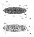
- This comprises the gas generating cell 101, the poles of which can be short-circuited or electrically connected to each other by means of the connecting means 102.
- the connection means 102 comprises the electrical resistor 103 and the switch 104.
- the resistor 103 may be, for example, an NTC, PTC or LDR resistor.
- the switch 104 may be, for example, a micro-film pressure switch.
- the gas generating cell 101 and the connecting means 102 are disposed inside the first enclosure 105 . This encloses the first-mentioned components gas-tight.
- the envelope 105 is, for example, a bag made of a plastic-aluminum composite material.
- the second enclosure 106 which has an outlet opening 107 .
- the second enclosure 106 and the first enclosure 105 define a cavity 108, herein present with a spongy substrate loaded with the media 109 to be dispensed.
- a gas 110 is generated by the gas generating cell 101 .
- the first sheath 105 expands, thereby reducing the cavity 108 between the first sheath and the second sheath.
- the pressure acting on the sponge-like carrier material 111 causes a discharge of the medium 109 to be discharged via the application opening 107.
Landscapes
- Engineering & Computer Science (AREA)
- Health & Medical Sciences (AREA)
- General Engineering & Computer Science (AREA)
- Mechanical Engineering (AREA)
- Biomedical Technology (AREA)
- Veterinary Medicine (AREA)
- Hematology (AREA)
- Life Sciences & Earth Sciences (AREA)
- Animal Behavior & Ethology (AREA)
- General Health & Medical Sciences (AREA)
- Public Health (AREA)
- Heart & Thoracic Surgery (AREA)
- Anesthesiology (AREA)
- Vascular Medicine (AREA)
- Physics & Mathematics (AREA)
- Fluid Mechanics (AREA)
- Infusion, Injection, And Reservoir Apparatuses (AREA)
- Apparatus Associated With Microorganisms And Enzymes (AREA)
Description
- Die vorliegende Erfindung betrifft ein Verfahren und eine Vorrichtung zum dosierten Austrag eines Mediums.
- Aus dem Stand der Technik ist es bereits seit längerem bekannt, Vorrichtungen zum dosierten Austrag von Medien mittels sogenannter Gaserzeugerzellen zu betreiben, so zum Beispiel aus der deutschen Patentschrift
DE 37 11 714 C2 . Bei Gaserzeugerzellen handelt es sich bekanntlich um elektrochemische Zellen mit einem positiven und einem negativen Pol, die, wenn ein elektrischer Strom zwischen den Polen fließt, eine zur Menge des fließenden Stroms proportionale Menge eines Gases freisetzen. In der Regel weisen sie eine Ruhespannung auf, worunter zu verstehen ist, dass beim elektrischen Verbinden der Pole ohne externe Triebkraft ein Strom zwischen den Polen fließt und die Gasentwicklung einsetzt. Meist liegen Gasentwicklungszellen in Form von Knopfzellen vor. - Aus der
US 6,520,936 B1 ist eine implantierbare Infusionspumpe bekannt, die eine Gasentwicklungszelle umfasst, die von einer ersten expandierbaren Hülle umschlossen ist. Die erste Hülle bildet mit dem Außengehäuse der Pumpe einen mit einem auszutragenden Medium gefüllten Hohlraum, der sich bei Gasentwicklung durch Expansion der ersten Hülle verkleinert und das Medium durch die Öffnung drückt. - Aus der
US 6,413,238 B1 ist ein Flüssigkeitsspender in Form einer Spritze bekannt. Die Spritze umfasst einen Druckkolben, der pneumatisch, beispielsweise mit Hilfe einer elektrochemischen Gaserzeugungszelle, bewegt wird. Die Gasmenge wird dabei mit einem gegenüber physikalischen, chemischen oder biologischen Parametern empfindlichen Sensor reguliert. - Die
DE 2 239 432 A1 betrifft eine Austragsvorrichtung für Medikamente umfassend einen elektrolytischen Gaserzeuger, der innerhalb eines Medikamentenreservoirs von einer flexiblen Membran umschlossen ist. Bei Gaserzeugung verkleinert sich das Reservoir und das auszutragende Medikament wird durch eine Öffnung gedrückt. - Die
WO 2005/044343 A1 betrifft eine Vorrichtung zur dosierten Abgabe von Flüssigkeit mittels einer Gasdruckquelle, die außerhalb einer Druckmittelkammer angeordnet ist. Bei der Gasdruckquelle handelt es sich nicht um eine elektrochemische Zelle. - In der
EP 0 209 644 A1 ist eine Austragsvorrichtung für Medikamente umfassend eine elektrochemische Pumpe, die von einem Medikamentenreservoir durch eine gasundurchlässige Membran separiert ist, beschieben. Durch Anlegen einer Spannung zwischen zwei Elektroden wird ein Gas erzeugt, das die Membran in Richtung des Medikamentenreservoirs ausdehnt. Es resultiert ein Medikamentenaustrag durch eine Öffnung. - In der
US 2004/0031695 sind elektrochemische N2-Entwicklungszellen beschrieben, die sich insbesondere als Gaserzeuger in Vorrichtungen zum Austragen von flüssigen Medien eignen. - Problematisch beim Einsatz von Gaserzeugerzellen in Dosiervorrichtungen ist häufig, dass die gasdichte Konstruktion der Vorrichtungen mit einem hohen technischen Aufwand verbunden ist. Dies gilt insbesondere, wenn als Gaserzeugerzelle Wasserstoffentwicklungszellen verwendet werden. Wasserstoffmoleküle sind sehr klein und können selbst durch metallische Barrieren diffundieren.
- Der vorliegenden Erfindung lag die Aufgabe zugrunde, eine mittels einer Gaserzeugerzelle betriebene Dosiervorrichtung bereitzustellen, bei der Dichtigkeitsprobleme vermieden werden oder zumindest minimiert sind. Gelöst wird diese Aufgabe durch die Vorrichtung mit den Merkmalen des Anspruchs 1. Bevorzugte Ausführungsformen der erfindungsgemäßen Vorrichtung sind in den abhängigen Ansprüchen 2 bis 11 definiert. Weiterhin ist auch das Verfahren mit den Merkmalen des Anspruchs 12 Gegenstand der vorliegenden Erfindung. Der Wortlaut sämtlicher Ansprüche wird hiermit durch Bezugnahme zum Inhalt der vorliegenden Beschreibung gemacht.
- Eine erfindungsgemäße Vorrichtung dient zum dosierten Austrag von Medien, insbesondere von flüssigen oder gasförmigen Medien. Sie umfaßt zwingend die folgenden Komponenten:
- Eine elektrochemische Zelle mit einem positiven und einem negativen Pol, die beim Fließen eines elektrischen Stroms zwischen den Polen eine zur Menge des fließenden Stroms proportionale Menge eines Gases freisetzt.
- Besonders bevorzugt können als elektrochemische Zellen Gasentwicklungszellen der in der
DE 35 32 335 A1 beschriebenen Bauart zum Einsatz kommen, insbesondere in der wasserstofferzeugenden Ausführungsform. Bevorzugt handelt es sich bei der elektrochemischen Zelle um eine Wasserstoffentwicklungszelle. - Ein Verbindungsmittel, gegebenenfalls einschließlich eines Schalters, über das die Pole der elektrochemischen Zelle miteinander verbunden werden können. Bei dem Verbindungsmittel handelt es sich im einfachsten Fall um einen elektrischen Leiter. In bevorzugten Ausführungsformen kann das Verbindungsmittel einen elektrischen Widerstand umfassen oder aus einem solchen bestehen. Bei dem Widerstand kann es sich grundsätzlich um einen regelbaren Widerstand handeln oder um einen Festwiderstand mit einem im wesentlichen konstanten Ohm-Wert. Bei dem Schalter handelt es sich beispielsweise um einen manuellen oder einen elektronischen Schalter.
- Bevorzugt ist gegebenfalls, dass der elektrische Widerstand seine elektrische Leitfähigkeit in Folge eines physikalischen, chemischen oder biologischen Parameters, der direkt auf den Widerstand wirkt oder mittels eines Sensors, der mit dem Widerstand gekoppelt ist, detektiert wird, ändert. So kann er selbst als Schalter fungieren.
- Insbesondere ist der Einsatz von temperaturabhängigen Widerständen, beispielsweise von Heißleiter- (NTC-) und Kaltleiter- (PTC-) widerständen möglich. Bekanntlich besteht ein NTC-Widerstand (NTC-Widerstand = Negative Temperature Coefficient Thermistor) aus einem Material, das einen negativen Temperaturkoeffizienten besitzt und somit bei hohen Temperaturen elektrischen Strom besser leitet als bei tiefen Temperaturen. Ein PTC-Widerstand (PTC-Widerstand = Positive Temperature Coefficient Thermistor) besteht dagegen aus einem Material, das einen positiven Temperaturkoeffizienten besitzt und somit bei tiefen Temperaturen elektrischen Strom besser leitet als bei hohen Temperaturen. Mit derartigen Widerständen sind Ausführungformen der erfindungsgemäßen Vorrichtung realisierbar, bei denen eine sich automatisch an die Umgebungstemperatur anpassende Dosierung des auszutragenden Mediums erfolgt.
- Weitere bekannte Widerstände, die in Folge der Änderung eines physikalischen Parameters ihre Leitfähigkeit ändern können, sind z.B. LDR-Widerstände (LDR = Light Dependent Resistor), spannungsabhängige Widerstände oder Widerstände, die auf mechanische Belastungen wie Druck, Zug oder Schall reagieren.
- Widerstände, die in Abhängigkeit eines chemischen oder biologischen Parameters ihre Leitfähigkeit für elektrisch Strom ändern, sind beispielsweise Widerstände, die auf Luftfeuchtigkeit, die Konzentration eines chemischen Stoffes, insbesondere eines Gases (z.B. Sauerstoff, Wasserstoff, Erdgas), oder einer biologischen Substanz (z.B. eines bakteriellen Keims) reagieren.
- Gegebenfalls kann das Verbindungsmittel auch einen regelbaren Widerstand und einen mit diesem gekoppelten Sensor, beispielsweise einem chemischen, biologischen oder physikalischen Sensor, umfassen. Wird von dem Sensor z.B. eine Überschreitung einer vordefinierten Konzentration einer biologischen Substanz oder eines Moleküls (z.B. Sauerstoff) oder einer bestimmten Temperatur oder ein Lichteinfall detektiert, so kann dieser, gegebenfalls über eine geeignete elektronische Schaltung, eine Erniedrigung des regelbaren Widerstands veranlassen. Zwischen den Polen der elektrochemischen Zelle fließt dann ein Strom, dessen Stärke von der detektierten Konzentration, Temperatur oder Lichtstärke abhängt.
- Eine erste, geschlossene Umhüllung, die mindestens teilweise, vorzugsweise vollständig, aus einem flexiblen, für das freigesetzte Gas undurchlässigen Material besteht.
- Die erste Umhüllung umschließt die elektrochemische Zelle gasdicht. Von der Zelle generiertes Gas kann nicht aus der ersten Umhüllung entweichen. Entsprechend resultiert aus einer Gaserzeugung eine Volumenexpansion der ersten Umhüllung. Zu diesem Zweck ist die erste Umhüllung bevorzugt aus einem flexiblen Material ausgebildet, insbesondere aus einem dehnbaren, also elastisch oder plastisch verformbaren, Material. Geeignet hierfür sind insbesondere Folien oder Gewebe aus Kunststoff und / oder Metall, insbesondere in Beutelform. Besonders bevorzugt können Verbundmaterialien zum Einsatz kommen, beispielsweise Folien oder Gewebe mit Schichten aus mehreren Materialen, beispielsweise Kunststofffolien mit einer Aluminiumschicht als Sperrschicht für den Wasserstoff. Insbesondere kann die erste Umhüllung auch in Teilen oder vollständig lichtdurchlässig ausgebildet sein.
- Erfindungsgemäß ist die erste Umhüllung entweder in einem Hohlraum angeordnet, in dem das auszutragende Medium angeordnet ist und aus dem das Medium über mindestens eine Austragsöffnung ausgetragen werden kann, oder aber sie steht über ein Arbeitsmedium in kommunizierender Verbindung mit einem solchen Hohlraum.
- Schwillt die erste Umhüllung in Folge einer Gasentwicklung der elektrochemischen Zelle an, so vergrößert sich ihr Volumen. Ist die erste Umhüllung in dem Hohlraum angeordnet, so verkleinert sich das Volumen des Hohlraums durch die anschwellende erste Umhüllung. Diese übt einen Druck auf das in dem Hohlraum befindliche Medium aus, das in der Folge durch mindestens eine die Begrenzung des Hohlraums durchstoßende Austragsöffnung ausgetragen werden kann. Steht die erste Umhüllung dagegen über ein Arbeitsmedium in kommunizierender Verbindung mit einem Hohlraum, in dem das auszutragende Medium angeordnet ist, so übt die anschwellende erste Umhüllung einen Druck mittelbar über das Arbeitsmedium auf das auszutragende Medium aus.
- Bei dem Arbeitsmedium handelt es sich bevorzugt um ein Gas, beispielsweise um Luft, oder eine Flüssigkeit, beispielsweise Wasser oder ein Öl. Der Austrag wird also gegebenenfalls pneumatisch oder hydraulisch bewirkt.
- Bevorzugt umfasst die erfindungsgemäße Vorrichtung eine zweite Umhüllung, die die mindestens eine Austragsöffnung aufweist, die erste Umhüllung umschließt und gemeinsam mit dieser den Hohlraum für das auszutragende Medium definiert.
- Die mindestens eine Austragsöffnung kann im Grunde nahezu beliebig ausgebildet sein. So kann es sich bei der mindestens einen Austragsöffnung beispielsweise um mindestens eine Pore in der Größenordnung eines aus wenigen Atomen bestehenden Moleküls handeln oder um eine Kanüle, abhängig vom Zweck und entsprechend der konkreten Ausgestaltung der erfindungsgemäßen Vorrichtung.
- In einer bevorzugten Ausführungsform der erfindungsgemäßen Vorrichtung ist nicht nur die elektrochemische Zelle innerhalb der ersten Umhüllung angeordnet sondern auch das Verbindungsmittel, gegebenfalls einschließlich des Schalters. Bei dem Schalter handelt es sich in dieser Ausführungsform bevorzugt um einen kontaktlos betätigbaren Schalter. Alternativ sind natürlich auch mechanische Druckschalter einsetzbar. In diesem Fall sollte gegebenenfalls nicht nur die erste Umhüllung flexibel ausgebildet sein sondern mindestens auch ein Teil der zweiten Umhüllung, damit eine Betätigung des Druckschalters möglich ist.
- Insbesondere, wenn Widerstände eingesetzt werden, deren elektrische Leitfähigkeit in Folge eines physikalischen, chemischen oder biologischen Parameters, der direkt auf den Widerstand wirkt, sich ändert, oder die regelbar sind und mit einem der erwähnten chemischen, biologischen oder physikalischen Sensoren gekoppelt sind, kann es allerdings auch bevorzugt sein, dass der Widerstand und/oder der Sensor außerhalb der ersten Umhüllung angeordnet ist, gegebenfalls auch außerhalb der zweiten Umhüllung. Für das Verbindungsmittel sind in dieser Ausführungsform entsprechende Durchlässe durch die erste Umhüllung, gegebenfalls auch durch die zweite Umhüllung, vorgesehen.
- Die zweite Umhüllung besteht bevorzugt zumindest teilweise, vorzugsweise vollständig, aus einer Folie oder aus einem Gewebe. Das Material aus dem die zweite Umhüllung besteht, muss im Gegensatz zu dem der ersten Umhüllung nicht zwingend gasdicht sein. Idealerweise sollte die zweite Umhüllung allerdings aus einem nicht dehnbaren Material bestehen, so dass ein Druckausgleich innerhalb der zweiten Umhüllung in Folge einer Volumenexpansion der ersten Umhüllung ausschließlich durch den gewünschten Auftrag des Mediums stattfinden kann. So kann es sich bei der zweiten Umhüllung beispielsweise um ein Gehäuse aus einem festen Material, beispielsweise aus einem Metallblech, Glas oder aus einem Kunststoffgussteil, handeln.
- Auch die zweite Umhüllung kann gegebenfalls in Teilen oder vollständig transparent ausgebildet sein.
- Der Hohlraum zwischen der ersten und der zweiten Umhüllung ist mit einem porösen elastischen Material, insbesondere mit einem Schwamm, befüllt, welches mit dem auszutragenden Medium beladen ist. Dieses Material kann mit dem auszutragenden Medium beispielsweise getränkt werden und dieses speichern.
- Alternativ kann das Medium auch in flüssiger, gelartiger oder pastenartiger oder fester Form in dem Hohlraum angeordnet sein.
- Bevorzugt handelt es sich bei dem Medium um ein Schmiermittel, ein Desinfektionsmittel, einen Duftstoff oder einen pharmazeutischen und/oder medizinischen Wirkstoff. Auch antibakterielle Mittel, antivirale Mittel, Reinigungsmittel, Haft- und Klebemittel in grundsätzlich jedweder Form und Zusammensetzung können mittels der erfindungsgemäßen Dosiervorrichtung ausgetragen werden.
- Losgelöst von einer konkreten Ausführungsform der erfindungsgemäßen Vorrichtung ist das erfindungsgemäße Verfahren zum dosierten Austrag eines solchen Mediums.
- Erfindungsgemäß wird zur Bewirkung des Austrags eine gaserzeugende elektrochemische Zelle in Betrieb genommen, die innerhalb einer geschlossenen, für das erzeugte Gas undurchlässigen Umhüllung angeordnet ist. In Übereinstimmung mit obigen Ausführungsformen schwillt in Folge der Gaserzeugung die Umhüllung an, wodurch das Volumen des Hohlraumes reduziert oder über ein Arbeitsmedium Druck auf das in dem Hohlraum angeordnete poröse elastische Material, welches mit dem auszutragenden Medium beladen ist, ausgeübt wird. Dadurch entsteht ein Druck, der auf das in dem Hohlraum enthaltene Medium wirkt, welches in der Folge aus dem Hohlraum ausgetragen wird.
- Weitere Merkmale und auch Vorteile der vorliegenden Erfindung ergeben sich aus der nun folgenden Beschreibung bevorzugter Ausführungsformen der erfindungsgemäßen Vorrichtung in Verbindung mit den Unteransprüchen. Die dargestellten Merkmale der erfindungsgemäßen Vorrichtung können jeweils für sich oder zu mehreren in Kombination bei einer Ausführungsform der Erfindung verwirklicht sein. Die Ausführungsbeispiele dienen lediglich zur Erläuterung und zum besseren Verständnis der Erfindung und sind in keiner Weise einschränkend zu verstehen.
-
- Fig. 1a
- zeigt schematisch eine Ausführungsform einer erfindungsgemäßen Vorrichtung vor ihrer Aktivierung.
- Fig. 1b
- zeigt die gleiche Ausführungsform der erfindungsgemäßen Vorrichtung nach ihrer Aktivierung.
- Dargestellt ist die Dosiervorrichtung 100. Diese umfasst die Gaserzeugungszelle 101, deren Pole mittels des Verbindungsmittels 102 kurzeschlossen bzw. elektrisch miteinander verbunden werden können. Das Verbindungsmittel 102 umfasst den elektrischen Widerstand 103 sowie den Schalter 104. Bei dem Widerstand 103 kann es sich beispielsweise um einen NTC-, PTC- oder LDR-Widerstand handeln. Bei dem Schalter 104 kann es sich beispielsweise um einen Mikro-Foliendruckschalter handeln. Die Gaserzeugungszelle 101 und das Verbindungsmittel 102 sind innerhalb der ersten Umhüllung 105 angeordnet. Diese umschließt die erstgenannten Komponenten gasdicht. Bei der Umhüllung 105 handelt es sich beispielsweise um einen Beutel aus einem Kunststoff-Aluminium-Verbundmaterial. Dieser ist wiederum innerhalb der zweiten Umhüllung 106 ausgebildet, die eine Austrittsöffnung 107 aufweist. Gemeinsam definieren die zweite Umhüllung 106 und die erste Umhüllung 105 einen Hohlraum 108, der vorliegend mit einem schwammartigen Trägermaterial, der mit dem auszutragenden Medium 109 beladen ist.
- Bei Inbetriebnahme der Gaserzeugungszelle 101 durch Schließen des Schalters 104 wird von der Gaserzeugsungszelle 101 ein Gas 110 erzeugt. In der Folge dehnt sich die erste Umhüllung 105 aus, wodurch der Hohlraum 108 zwischen der ersten Umhüllung und der zweiten Umhüllung verkleinert wird. Der dabei auf das schwammartige Trägermaterial 111 wirkende Druck bewirkt einen Austritt des auszutragenden Mediums 109 über die Auftragsöffnung 107.
Claims (12)
- Vorrichtung zum dosierten Austrag eines Mediums, umfassend• eine elektrochemische Zelle (101) mit einem positiven und einem negativen Pol, die beim Fließen eines elektrischen Stroms zwischen den Polen eine zur Menge des fließenden Stromes proportionale Menge eines Gases (110) freisetzt,• ein Verbindungsmittel (102), gegebenenfalls einschließlich eines Schalters (104), über das die Pole der elektrochemischen Zelle (101) miteinander verbunden werden können,• eine erste, geschlossene Umhüllung (105) zumindest teilweise bestehend aus einem flexiblen, für das freigesetzte Gas undurchlässigen Material, die die elektrochemische Zelle (101) gasdicht umschließt,
wobei die erste Umhüllung (105) in einem Hohlraum (108) angeordnet ist, in dem das auszutragende Medium (109) angeordnet ist und aus dem das Medium (109) über mindestens eine Austragsöffnung (107) ausgetragen werden kann oder die erste Umhüllung (105) über ein Arbeitsmedium in kommunizierender Verbindung mit einem solchen Hohlraum (108) steht, dadurch gekennzeichnet, dass der Hohlraum (108) mit einem porösen elastischen Material befüllt ist, welches mit dem auszutragenden Medium (109) beladen ist. - Vorrichtung nach Anspruch 1, dadurch gekennzeichnet, dass sie eine zweite Umhüllung (106) umfasst, die die mindestens eine Austragsöffnung (107) aufweist, die erste Umhüllung (105) umschließt und gemeinsam mit dieser den Hohlraum (108) bildet.
- Vorrichtung nach Anspruch 1 oder Anspruch 2, dadurch gekennzeichnet, dass die elektrochemische Zelle (101) eine Wasserstoffentwicklungszelle ist.
- Vorrichtung nach einem der vorhergehenden Ansprüche, dadurch gekennzeichnet, dass das Verbindungsmittel (102) einen elektrischen Widerstand (103) umfasst.
- Vorrichtung nach einem der vorhergehenden Ansprüche, dadurch gekennzeichnet, dass es sich bei dem elektrischen Widerstand (103) um einen Festwiderstand mit einem im Wesentlichen konstanten Ohm-Wert oder um einen regelbaren Widerstand handelt.
- Vorrichtung nach einem der vorhergehenden Ansprüche, dadurch gekennzeichnet, der elektrische Widerstand (103) seine elektrische Leitfähigkeit in Folge eines physikalischen, chemischen oder biologischen Parameters, der direkt auf den Widerstand wirkt oder mittels eines Sensors, der mit dem Widerstand gekoppelt ist, detektiert wird, ändert.
- Vorrichtung nach einem der vorhergehenden Ansprüche, dadurch gekennzeichnet, dass die erste Umhüllung (105) aus einer Folie oder aus einem Gewebe besteht.
- Vorrichtung nach einem der vorhergehenden Ansprüche, dadurch gekennzeichnet, dass das Verbindungsmittel (102), vorzugsweise einschließlich des Schalters (104), innerhalb der ersten Umhüllung (105) angeordnet ist.
- Vorrichtung nach einem der vorhergehenden Ansprüche, dadurch gekennzeichnet, dass die zweite Umhüllung (106) zumindest teilweise aus einem flexiblen Material, insbesondere aus einer Folie oder aus einem Gewebe, besteht.
- Vorrichtung nach einem der vorhergehenden Ansprüche, dadurch gekennzeichnet, dass der Hohlraum (108) mit einem Schwamm befüllt ist, welcher mit dem auszutragenden Medium (109) beladen ist.
- Vorrichtung nach einem der vorhergehenden Ansprüche, dadurch gekennzeichnet, dass das auszutragende Medium (109) ein Schmiermittel, ein Desinfektionsmittel, ein Duftstoff oder ein pharmazeutischer Wirkstoff ist.
- Verfahren zum dosierten Austrag eines Mediums (109), das innerhalb eines Hohlraums (108) angeordnet ist, der mit einem porösen elastischen Material befüllt ist, welches mit dem auszutragenden Medium (109) beladen ist, wobei zur Bewirkung des Austrags eine gaserzeugende elektrochemische Zelle (102) in Betrieb genommen wird, die innerhalb einer geschlossenen, für das erzeugte Gas undurchlässigen Umhüllung (105) angeordnet ist und durch die in Folge der Gaserzeugung anschwellende Umhüllung (105) das Volumen des Hohlraumes (108) reduziert oder über ein Arbeitsmedium Druck auf das in dem Hohlraum (108) angeordnete auszutragende Medium (109) ausgeübt wird.
Priority Applications (1)
| Application Number | Priority Date | Filing Date | Title |
|---|---|---|---|
| EP12171534.6A EP2674623B1 (de) | 2012-06-11 | 2012-06-11 | Verfahren und Vorrichtung zum dosierten Austrag eines Mediums |
Applications Claiming Priority (1)
| Application Number | Priority Date | Filing Date | Title |
|---|---|---|---|
| EP12171534.6A EP2674623B1 (de) | 2012-06-11 | 2012-06-11 | Verfahren und Vorrichtung zum dosierten Austrag eines Mediums |
Publications (2)
| Publication Number | Publication Date |
|---|---|
| EP2674623A1 EP2674623A1 (de) | 2013-12-18 |
| EP2674623B1 true EP2674623B1 (de) | 2015-09-23 |
Family
ID=46318947
Family Applications (1)
| Application Number | Title | Priority Date | Filing Date |
|---|---|---|---|
| EP12171534.6A Active EP2674623B1 (de) | 2012-06-11 | 2012-06-11 | Verfahren und Vorrichtung zum dosierten Austrag eines Mediums |
Country Status (1)
| Country | Link |
|---|---|
| EP (1) | EP2674623B1 (de) |
Families Citing this family (2)
| Publication number | Priority date | Publication date | Assignee | Title |
|---|---|---|---|---|
| EP3297053B1 (de) | 2016-09-19 | 2018-11-07 | VARTA Microbattery GmbH | Gaserzeugerzelle mit aussenliegender widerstandsfolie |
| EP3297062B1 (de) | 2016-09-19 | 2018-11-07 | VARTA Microbattery GmbH | Elektrochemische zelle zur erzeugung von wasserstoff oder sauerstoff |
Family Cites Families (7)
| Publication number | Priority date | Publication date | Assignee | Title |
|---|---|---|---|---|
| EP0209644A1 (de) * | 1985-05-02 | 1987-01-28 | Ivac Corporation | Elektrochemikalisch gesteuerte Arzneimittelabgabevorrichtung |
| DE3532335A1 (de) | 1985-09-11 | 1987-03-12 | Winsel August | Galvanische zelle zur entwicklung von wasserstoff bzw. sauerstoff |
| DE3711714A1 (de) | 1987-04-07 | 1988-10-27 | Winsel August | Vorrichtung zur foerderung pastoeser massen und fluessigkeiten und verfahren zur befuellung und zum betrieb |
| CA2243219A1 (en) * | 1998-07-14 | 2000-01-14 | A.T.S. Electro-Lube Holdings Ltd. | Electrolytic generation of nitrogen |
| EP1183059A1 (de) * | 1999-06-08 | 2002-03-06 | Medical Research Group, Inc. | Vorrichtung zur infusion eines fluides unter verwendung von chemischer reaktion in einer implantierten infusionsvorrichtung |
| US6413238B1 (en) * | 1999-09-17 | 2002-07-02 | Baxter International Inc | Fluid dispenser with stabilized fluid flow |
| AT412945B (de) * | 2003-11-05 | 2005-09-26 | Pro Med Medizinische Produktio | Vorrichtung zur dosierten abgabe von flüssigkeit |
-
2012
- 2012-06-11 EP EP12171534.6A patent/EP2674623B1/de active Active
Also Published As
| Publication number | Publication date |
|---|---|
| EP2674623A1 (de) | 2013-12-18 |
Similar Documents
| Publication | Publication Date | Title |
|---|---|---|
| DE60011078T2 (de) | Strukturen mit veränderlichem Leitwert | |
| EP1987761B1 (de) | Schlauchförmiger Sensor zum Nachweis eines Analyten | |
| EP0278954B1 (de) | Gasbetriebene dosiervorrichtung | |
| DE102017111119A1 (de) | Verdampfereinheit für einen Inhalator | |
| DE10313005A1 (de) | Revervebatterie, Verfahren zu deren Herstellung und Betriebsverfahren für eine derartige Reservebatterie | |
| DE2911343A1 (de) | Elektrodenvorrichtung fuer die transkutane pco tief 2 -messung | |
| EP2674623B1 (de) | Verfahren und Vorrichtung zum dosierten Austrag eines Mediums | |
| WO2015018619A1 (de) | Einrichtung zur irreversiblen erfassung einer überschreitung einer vorbestimmten temperatur sowie verfahren zur herstellung der einrichtung | |
| DE102011009187A1 (de) | Applikator für eine Dentalflüssigkeit | |
| EP2582290B1 (de) | Befeuchtete sensorkontakteinheit | |
| EP3169993B1 (de) | Referenzelektrodenanordnung für elektrochemischen sensor und elektrochemischer sensor | |
| CH670162A5 (de) | ||
| EP3754329A1 (de) | Wasserstoffsensor und verfahren zu dessen herstellung, messvorrichtung und verfahren zum messen einer wasserstoffkonzentration | |
| DE10210051A1 (de) | Vorrichtung zum elektrochemischen Nachweis einer Nukleotidsequenz, Analyse-Kassette für eine solche Vorrichtung und Verfahren zur Herstellung einer solchen Analyse-Kassette | |
| DE102016200211A1 (de) | Medikamentenabgabe-Vorrichtung und eine Medikamentenabgabe-Baugruppe | |
| DE10308619B4 (de) | Vorrichtung zum Austragen eines Riech- bzw. Duftstoffs | |
| DE19853286B4 (de) | Verfahren zum Steuern eines chemischen Ventiles | |
| DE102006012799A1 (de) | Potentiometrische Messkette | |
| DE102011004799B4 (de) | Statusindikator für temperaturempfindliche Güter | |
| DE102009051216A1 (de) | Elektrochemischer Energiespeicher und Verfahren zur thermischen Stabilisierung eines elektrochemischen Energiespeichers | |
| EP3297053B1 (de) | Gaserzeugerzelle mit aussenliegender widerstandsfolie | |
| DE10332289A1 (de) | Fluidsystem mit Sicherungseinrichtung | |
| EP3035977A1 (de) | Transdermales therapeutisches system mit druckerzeugungsvorrichtung | |
| DE442671C (de) | Vorrichtung zur getrennten Aufbewahrung der zur Herstellung von Loesungen dienenden Bestandteile | |
| KR102288678B1 (ko) | 전위차 소재를 이용한 전도성 패턴이 구비된 마스크팩용 시트 및 그 제조방법 |
Legal Events
| Date | Code | Title | Description |
|---|---|---|---|
| PUAI | Public reference made under article 153(3) epc to a published international application that has entered the european phase |
Free format text: ORIGINAL CODE: 0009012 |
|
| AK | Designated contracting states |
Kind code of ref document: A1 Designated state(s): AL AT BE BG CH CY CZ DE DK EE ES FI FR GB GR HR HU IE IS IT LI LT LU LV MC MK MT NL NO PL PT RO RS SE SI SK SM TR |
|
| AX | Request for extension of the european patent |
Extension state: BA ME |
|
| 17P | Request for examination filed |
Effective date: 20140120 |
|
| RBV | Designated contracting states (corrected) |
Designated state(s): AL AT BE BG CH CY CZ DE DK EE ES FI FR GB GR HR HU IE IS IT LI LT LU LV MC MK MT NL NO PL PT RO RS SE SI SK SM TR |
|
| GRAP | Despatch of communication of intention to grant a patent |
Free format text: ORIGINAL CODE: EPIDOSNIGR1 |
|
| RIC1 | Information provided on ipc code assigned before grant |
Ipc: F04B 43/06 20060101ALI20150508BHEP Ipc: F04B 43/04 20060101ALI20150508BHEP Ipc: A61M 5/155 20060101ALI20150508BHEP Ipc: F04B 9/123 20060101AFI20150508BHEP Ipc: A61M 5/142 20060101ALI20150508BHEP |
|
| GRAP | Despatch of communication of intention to grant a patent |
Free format text: ORIGINAL CODE: EPIDOSNIGR1 |
|
| INTG | Intention to grant announced |
Effective date: 20150602 |
|
| INTG | Intention to grant announced |
Effective date: 20150626 |
|
| GRAS | Grant fee paid |
Free format text: ORIGINAL CODE: EPIDOSNIGR3 |
|
| GRAA | (expected) grant |
Free format text: ORIGINAL CODE: 0009210 |
|
| AK | Designated contracting states |
Kind code of ref document: B1 Designated state(s): AL AT BE BG CH CY CZ DE DK EE ES FI FR GB GR HR HU IE IS IT LI LT LU LV MC MK MT NL NO PL PT RO RS SE SI SK SM TR |
|
| REG | Reference to a national code |
Ref country code: GB Ref legal event code: FG4D Free format text: NOT ENGLISH |
|
| REG | Reference to a national code |
Ref country code: CH Ref legal event code: EP |
|
| REG | Reference to a national code |
Ref country code: AT Ref legal event code: REF Ref document number: 751403 Country of ref document: AT Kind code of ref document: T Effective date: 20151015 |
|
| REG | Reference to a national code |
Ref country code: IE Ref legal event code: FG4D Free format text: LANGUAGE OF EP DOCUMENT: GERMAN |
|
| REG | Reference to a national code |
Ref country code: DE Ref legal event code: R096 Ref document number: 502012004665 Country of ref document: DE |
|
| REG | Reference to a national code |
Ref country code: NL Ref legal event code: MP Effective date: 20150923 |
|
| PG25 | Lapsed in a contracting state [announced via postgrant information from national office to epo] |
Ref country code: NO Free format text: LAPSE BECAUSE OF FAILURE TO SUBMIT A TRANSLATION OF THE DESCRIPTION OR TO PAY THE FEE WITHIN THE PRESCRIBED TIME-LIMIT Effective date: 20151223 Ref country code: LV Free format text: LAPSE BECAUSE OF FAILURE TO SUBMIT A TRANSLATION OF THE DESCRIPTION OR TO PAY THE FEE WITHIN THE PRESCRIBED TIME-LIMIT Effective date: 20150923 Ref country code: GR Free format text: LAPSE BECAUSE OF FAILURE TO SUBMIT A TRANSLATION OF THE DESCRIPTION OR TO PAY THE FEE WITHIN THE PRESCRIBED TIME-LIMIT Effective date: 20151224 Ref country code: FI Free format text: LAPSE BECAUSE OF FAILURE TO SUBMIT A TRANSLATION OF THE DESCRIPTION OR TO PAY THE FEE WITHIN THE PRESCRIBED TIME-LIMIT Effective date: 20150923 Ref country code: LT Free format text: LAPSE BECAUSE OF FAILURE TO SUBMIT A TRANSLATION OF THE DESCRIPTION OR TO PAY THE FEE WITHIN THE PRESCRIBED TIME-LIMIT Effective date: 20150923 |
|
| REG | Reference to a national code |
Ref country code: DE Ref legal event code: R082 Ref document number: 502012004665 Country of ref document: DE Representative=s name: OSTERTAG & PARTNER, PATENTANWAELTE MBB, DE Ref country code: DE Ref legal event code: R082 Ref document number: 502012004665 Country of ref document: DE Representative=s name: PATENTANWALTSKANZLEI CARTAGENA PARTNERSCHAFTSG, DE |
|
| REG | Reference to a national code |
Ref country code: LT Ref legal event code: MG4D |
|
| PG25 | Lapsed in a contracting state [announced via postgrant information from national office to epo] |
Ref country code: SE Free format text: LAPSE BECAUSE OF FAILURE TO SUBMIT A TRANSLATION OF THE DESCRIPTION OR TO PAY THE FEE WITHIN THE PRESCRIBED TIME-LIMIT Effective date: 20150923 Ref country code: RS Free format text: LAPSE BECAUSE OF FAILURE TO SUBMIT A TRANSLATION OF THE DESCRIPTION OR TO PAY THE FEE WITHIN THE PRESCRIBED TIME-LIMIT Effective date: 20150923 Ref country code: HR Free format text: LAPSE BECAUSE OF FAILURE TO SUBMIT A TRANSLATION OF THE DESCRIPTION OR TO PAY THE FEE WITHIN THE PRESCRIBED TIME-LIMIT Effective date: 20150923 |
|
| PG25 | Lapsed in a contracting state [announced via postgrant information from national office to epo] |
Ref country code: NL Free format text: LAPSE BECAUSE OF FAILURE TO SUBMIT A TRANSLATION OF THE DESCRIPTION OR TO PAY THE FEE WITHIN THE PRESCRIBED TIME-LIMIT Effective date: 20150923 |
|
| PG25 | Lapsed in a contracting state [announced via postgrant information from national office to epo] |
Ref country code: ES Free format text: LAPSE BECAUSE OF FAILURE TO SUBMIT A TRANSLATION OF THE DESCRIPTION OR TO PAY THE FEE WITHIN THE PRESCRIBED TIME-LIMIT Effective date: 20150923 Ref country code: IT Free format text: LAPSE BECAUSE OF FAILURE TO SUBMIT A TRANSLATION OF THE DESCRIPTION OR TO PAY THE FEE WITHIN THE PRESCRIBED TIME-LIMIT Effective date: 20150923 Ref country code: SK Free format text: LAPSE BECAUSE OF FAILURE TO SUBMIT A TRANSLATION OF THE DESCRIPTION OR TO PAY THE FEE WITHIN THE PRESCRIBED TIME-LIMIT Effective date: 20150923 Ref country code: CZ Free format text: LAPSE BECAUSE OF FAILURE TO SUBMIT A TRANSLATION OF THE DESCRIPTION OR TO PAY THE FEE WITHIN THE PRESCRIBED TIME-LIMIT Effective date: 20150923 Ref country code: IS Free format text: LAPSE BECAUSE OF FAILURE TO SUBMIT A TRANSLATION OF THE DESCRIPTION OR TO PAY THE FEE WITHIN THE PRESCRIBED TIME-LIMIT Effective date: 20160123 Ref country code: EE Free format text: LAPSE BECAUSE OF FAILURE TO SUBMIT A TRANSLATION OF THE DESCRIPTION OR TO PAY THE FEE WITHIN THE PRESCRIBED TIME-LIMIT Effective date: 20150923 |
|
| PG25 | Lapsed in a contracting state [announced via postgrant information from national office to epo] |
Ref country code: RO Free format text: LAPSE BECAUSE OF FAILURE TO SUBMIT A TRANSLATION OF THE DESCRIPTION OR TO PAY THE FEE WITHIN THE PRESCRIBED TIME-LIMIT Effective date: 20150923 Ref country code: PT Free format text: LAPSE BECAUSE OF FAILURE TO SUBMIT A TRANSLATION OF THE DESCRIPTION OR TO PAY THE FEE WITHIN THE PRESCRIBED TIME-LIMIT Effective date: 20160125 Ref country code: PL Free format text: LAPSE BECAUSE OF FAILURE TO SUBMIT A TRANSLATION OF THE DESCRIPTION OR TO PAY THE FEE WITHIN THE PRESCRIBED TIME-LIMIT Effective date: 20150923 |
|
| REG | Reference to a national code |
Ref country code: FR Ref legal event code: PLFP Year of fee payment: 5 |
|
| REG | Reference to a national code |
Ref country code: DE Ref legal event code: R097 Ref document number: 502012004665 Country of ref document: DE |
|
| PLBE | No opposition filed within time limit |
Free format text: ORIGINAL CODE: 0009261 |
|
| STAA | Information on the status of an ep patent application or granted ep patent |
Free format text: STATUS: NO OPPOSITION FILED WITHIN TIME LIMIT |
|
| 26N | No opposition filed |
Effective date: 20160624 |
|
| PG25 | Lapsed in a contracting state [announced via postgrant information from national office to epo] |
Ref country code: DK Free format text: LAPSE BECAUSE OF FAILURE TO SUBMIT A TRANSLATION OF THE DESCRIPTION OR TO PAY THE FEE WITHIN THE PRESCRIBED TIME-LIMIT Effective date: 20150923 |
|
| PG25 | Lapsed in a contracting state [announced via postgrant information from national office to epo] |
Ref country code: SI Free format text: LAPSE BECAUSE OF FAILURE TO SUBMIT A TRANSLATION OF THE DESCRIPTION OR TO PAY THE FEE WITHIN THE PRESCRIBED TIME-LIMIT Effective date: 20150923 |
|
| PG25 | Lapsed in a contracting state [announced via postgrant information from national office to epo] |
Ref country code: BE Free format text: LAPSE BECAUSE OF NON-PAYMENT OF DUE FEES Effective date: 20160630 |
|
| PG25 | Lapsed in a contracting state [announced via postgrant information from national office to epo] |
Ref country code: MC Free format text: LAPSE BECAUSE OF FAILURE TO SUBMIT A TRANSLATION OF THE DESCRIPTION OR TO PAY THE FEE WITHIN THE PRESCRIBED TIME-LIMIT Effective date: 20150923 |
|
| REG | Reference to a national code |
Ref country code: CH Ref legal event code: PL |
|
| REG | Reference to a national code |
Ref country code: IE Ref legal event code: MM4A |
|
| PG25 | Lapsed in a contracting state [announced via postgrant information from national office to epo] |
Ref country code: LI Free format text: LAPSE BECAUSE OF NON-PAYMENT OF DUE FEES Effective date: 20160630 Ref country code: CH Free format text: LAPSE BECAUSE OF NON-PAYMENT OF DUE FEES Effective date: 20160630 |
|
| PG25 | Lapsed in a contracting state [announced via postgrant information from national office to epo] |
Ref country code: IE Free format text: LAPSE BECAUSE OF NON-PAYMENT OF DUE FEES Effective date: 20160611 |
|
| REG | Reference to a national code |
Ref country code: FR Ref legal event code: PLFP Year of fee payment: 6 |
|
| PG25 | Lapsed in a contracting state [announced via postgrant information from national office to epo] |
Ref country code: HU Free format text: LAPSE BECAUSE OF FAILURE TO SUBMIT A TRANSLATION OF THE DESCRIPTION OR TO PAY THE FEE WITHIN THE PRESCRIBED TIME-LIMIT; INVALID AB INITIO Effective date: 20120611 Ref country code: SM Free format text: LAPSE BECAUSE OF FAILURE TO SUBMIT A TRANSLATION OF THE DESCRIPTION OR TO PAY THE FEE WITHIN THE PRESCRIBED TIME-LIMIT Effective date: 20150923 Ref country code: CY Free format text: LAPSE BECAUSE OF FAILURE TO SUBMIT A TRANSLATION OF THE DESCRIPTION OR TO PAY THE FEE WITHIN THE PRESCRIBED TIME-LIMIT Effective date: 20150923 |
|
| REG | Reference to a national code |
Ref country code: FR Ref legal event code: PLFP Year of fee payment: 7 |
|
| PG25 | Lapsed in a contracting state [announced via postgrant information from national office to epo] |
Ref country code: LU Free format text: LAPSE BECAUSE OF NON-PAYMENT OF DUE FEES Effective date: 20160611 Ref country code: MT Free format text: LAPSE BECAUSE OF FAILURE TO SUBMIT A TRANSLATION OF THE DESCRIPTION OR TO PAY THE FEE WITHIN THE PRESCRIBED TIME-LIMIT Effective date: 20150923 Ref country code: TR Free format text: LAPSE BECAUSE OF FAILURE TO SUBMIT A TRANSLATION OF THE DESCRIPTION OR TO PAY THE FEE WITHIN THE PRESCRIBED TIME-LIMIT Effective date: 20150923 Ref country code: MK Free format text: LAPSE BECAUSE OF FAILURE TO SUBMIT A TRANSLATION OF THE DESCRIPTION OR TO PAY THE FEE WITHIN THE PRESCRIBED TIME-LIMIT Effective date: 20150923 |
|
| PG25 | Lapsed in a contracting state [announced via postgrant information from national office to epo] |
Ref country code: BG Free format text: LAPSE BECAUSE OF FAILURE TO SUBMIT A TRANSLATION OF THE DESCRIPTION OR TO PAY THE FEE WITHIN THE PRESCRIBED TIME-LIMIT Effective date: 20150923 |
|
| REG | Reference to a national code |
Ref country code: AT Ref legal event code: MM01 Ref document number: 751403 Country of ref document: AT Kind code of ref document: T Effective date: 20170611 |
|
| PG25 | Lapsed in a contracting state [announced via postgrant information from national office to epo] |
Ref country code: AL Free format text: LAPSE BECAUSE OF FAILURE TO SUBMIT A TRANSLATION OF THE DESCRIPTION OR TO PAY THE FEE WITHIN THE PRESCRIBED TIME-LIMIT Effective date: 20150923 |
|
| PG25 | Lapsed in a contracting state [announced via postgrant information from national office to epo] |
Ref country code: AT Free format text: LAPSE BECAUSE OF NON-PAYMENT OF DUE FEES Effective date: 20170611 |
|
| REG | Reference to a national code |
Ref country code: DE Ref legal event code: R082 Ref document number: 502012004665 Country of ref document: DE Representative=s name: OSTERTAG & PARTNER, PATENTANWAELTE MBB, DE |
|
| P01 | Opt-out of the competence of the unified patent court (upc) registered |
Effective date: 20230526 |
|
| PGFP | Annual fee paid to national office [announced via postgrant information from national office to epo] |
Ref country code: GB Payment date: 20240620 Year of fee payment: 13 |
|
| PGFP | Annual fee paid to national office [announced via postgrant information from national office to epo] |
Ref country code: DE Payment date: 20240621 Year of fee payment: 13 |
|
| PGFP | Annual fee paid to national office [announced via postgrant information from national office to epo] |
Ref country code: FR Payment date: 20240621 Year of fee payment: 13 |