EP2674548A2 - Conveyor device for bulk material and/or fibrous material - Google Patents
Conveyor device for bulk material and/or fibrous material Download PDFInfo
- Publication number
- EP2674548A2 EP2674548A2 EP13002940.8A EP13002940A EP2674548A2 EP 2674548 A2 EP2674548 A2 EP 2674548A2 EP 13002940 A EP13002940 A EP 13002940A EP 2674548 A2 EP2674548 A2 EP 2674548A2
- Authority
- EP
- European Patent Office
- Prior art keywords
- loosening
- shaft
- elements
- housing
- impact
- Prior art date
- Legal status (The legal status is an assumption and is not a legal conclusion. Google has not performed a legal analysis and makes no representation as to the accuracy of the status listed.)
- Withdrawn
Links
Images


Classifications
-
- E—FIXED CONSTRUCTIONS
- E04—BUILDING
- E04F—FINISHING WORK ON BUILDINGS, e.g. STAIRS, FLOORS
- E04F21/00—Implements for finishing work on buildings
- E04F21/02—Implements for finishing work on buildings for applying plasticised masses to surfaces, e.g. plastering walls
- E04F21/06—Implements for applying plaster, insulating material, or the like
- E04F21/08—Mechanical implements
- E04F21/085—Mechanical implements for filling building cavity walls with insulating materials
-
- E—FIXED CONSTRUCTIONS
- E04—BUILDING
- E04F—FINISHING WORK ON BUILDINGS, e.g. STAIRS, FLOORS
- E04F21/00—Implements for finishing work on buildings
- E04F21/02—Implements for finishing work on buildings for applying plasticised masses to surfaces, e.g. plastering walls
- E04F21/06—Implements for applying plaster, insulating material, or the like
- E04F21/08—Mechanical implements
- E04F21/12—Mechanical implements acting by gas pressure, e.g. steam pressure
Definitions
- the invention relates to a conveying device for bulk material and / or fiber material, in particular a blowing insulation conveying device, comprising a loosening device for loosening the bulk material and / or fiber material, wherein the loosening device comprises: a housing having a longitudinal axis, the conveying direction of the bulk material to be conveyed and / or fiber material, and at least one loosening element comprising a shaft which is rotatably mounted in the housing about an axis and driven by a motor, wherein the axis is arranged perpendicular to the longitudinal axis, wherein on the shaft a number of impact elements are rotatably mounted.
- a generic device is for example from the US 3,051,398 A known.
- a device of this type is used in particular to spend a fibrous insulating material - promoted in a stream of air - to its destination, for example, in hollow chambers, which are formed in a roof truss to fill said hollow chambers tightly with the insulating material.
- Such a device is further, for example, from the EP 1 520 948 A2 known.
- the material delivered pressed in a container is loosened up by the conveyor device by means of a chopper and the material thus prepared is conveyed in a transport line in the airstream to its destination.
- the device that accomplishes the loosening of the material is also referred to as a rotary valve.
- the fiber material may be cellulose. If, what has recently been preferred, the fiber material is made of wood, special difficulties arise. The wood fibers are pressed in turn, d. H. Delivered in highly compressed form, then as fanned wood fibers to Dämmstelle, for example, in hollow chambers of a roof, to be promoted. Due to the different structures of the fibrous wood particles, these do not disintegrate into individual fibers as easily as in the case of cellulose.
- the invention has for its object to provide a conveyor of the type mentioned in such a way that it is possible, even difficult ceremonimaschinende materials, in particular wood, sufficiently mecanicmaschinen and optimally promote, so that the volume to be filled with the fiber material well and Hohlstellen- can be filled freely.
- the initially highly compressed present insulating material is therefore to be frayed in an improved manner and distribute as evenly as possible in a compartment to be filled with him.
- the device should be simple in construction, so that a cost-effective production is possible.
- the housing is designed as a tube with a circular cross-section, wherein in the housing in the conveying direction consecutively at least two loosening elements, preferably three loosening elements are arranged, wherein two consecutive in the conveying direction Auflock ceremoniess institute for opposing rotation are formed, wherein the impact elements extend from the shaft to the inner circumference of the tubular housing, wherein in the conveying direction before and / or behind the last impact element, a device for blowing air is arranged.
- Said loosening device is provided as a separate element, which is effectively arranged between the device for loosening the pressed material (rotary valve) and the end of the fiber material blown-in hose.
- a preferred solution provides that two loosening elements following one another in the conveying direction rotate in opposite directions. Accordingly, in the case of three loosening elements, the first and the third loosening element rotate in the same direction, while the loosening element arranged therebetween rotates in opposite directions.
- the striking elements accordingly extend from the shaft to the inner periphery of the tubular housing. This is to be understood that only a sufficient gap for proper function between the radially outer end of the striking elements and the housing inner circumference remains when the striking element comes closest to the housing inner circumference.
- This gap is preferably in the range between 3 and 30 mm, preferably between 5 and 15 mm.
- the striking elements may extend radially away from the shaft. It is also possible for the impact elements to extend away from the shaft at least in sections at an angle, preferably between 10 ° and 50 °, to the radial direction.
- a particularly good loosening effect is achieved if a first loosening element is arranged in a region of the housing lying in the conveying direction, the impact elements extending radially away from the shaft of the first loosening element, and a second loosening element being arranged in a region following in the conveying direction wherein the striking elements extend from the shaft of the second loosening element away from the shaft at least in sections at an angle to the radial direction.
- the impact elements can be connected to each other at a location spaced from the shaft, for example by a ring having a slightly smaller diameter than the inner diameter of the tubular housing.
- the impact elements can be rotatably connected via a positive connection, in particular via a polygonal profile, with the shaft.
- a striking element can also be connected to a hub part, in particular welded, and the hub part can then be non-rotatably connected via the positive connection with the shaft.
- a further improvement of the loosening effect and improved further promotion of the fiberized material are achieved in that a device for blowing in air is arranged in the conveying direction before and / or behind the last impact element in the conveying direction.
- This device can be designed as a ring element, in which a number of air injection nozzles are arranged over the circumference. Angular adjustment of the air injection nozzles, the fiberized material can be imparted a twist in the delivery hose, which supports the promotion of the material.
- a particularly good defibration and promotion of the material is achieved when both said end of the loosening device and at the end of the tube each said means are provided for blowing air, preferably at the beginning of the loosening device.
- the impact elements of a loosening element which are arranged on the shaft, thus forming a kind of rotation grid, which is arranged rotationally driven in the housing.
- the tubular housing with the striking elements according to the invention which come close to the housing inner circumference, allows efficient fibrillation of the material to be conveyed with the significant advantage that there is a very compact and space-saving device that is easy to transport. This is important because of the purpose of the device since it must be mobile.
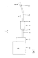
- a conveyor 1 for conveying wood fibers 2 is outlined.
- the wood fibers have a substantially linear extension and a length between about 2 and about 8 mm.
- the wood fibers 2 are delivered in a pressed state and are initially in a container 15. It is necessary to loosen up the present in a pressed state wood fibers and promote, for example, to bring them tightly packed in cavities of a roof truss can.
- the conveyor device 1 a device 12 for loosening the pressed wood fibers, which is sometimes referred to as a rotary valve.
- the device 12 performs a chopping process by which the fibers are loosened.
- the already partially frayed material 2 passes through a hose 13 in a conveying direction F to a loosening device 3.
- This device further loosens the fiber material 2 and brings it into a virtually completely frayed state.
- Via a further hose 14, the frayed material 2 is further blown in the conveying direction F to its destination.
- devices 11 for blowing in air are provided at three points, namely in front of the loosening device 3, behind the loosening device 3 and at the end of the hose 14.
- the devices 11 include nozzles that the Loosening and turbulence of the wood fibers 2 favor. If appropriate, further such devices 11 can be arranged in the flow or conveying path of the wood fibers 2.
- the loosening device 3 is outlined with different details.
- the loosening device 3, which constitutes a separate element in addition to the device 12, has a tubular housing 4 which has a longitudinal axis L.
- the longitudinal axis L coincides with the conveying direction F.
- the loosening elements 5 are rotating components which rotate about an axis a which is perpendicular to the longitudinal axis L.
- a shaft 6 is provided, which is rotatably mounted in the housing 4 by means of suitable bearings 16.
- a number of striking elements 8 are arranged in a rotationally fixed manner on the shaft 6.
- the rotary drive of the shaft 6 is effected by a motor 7, which preferably rotates the shaft between 2.500 and 4,000 revolutions per minute, in which case the two loosening elements 5 preferably rotate in opposite directions.
- the striking elements 8 can, as it Fig. 3 shows, so be arranged on the shaft 6, that they extend radially. Alternatively, it is also possible - and show that FIGS. 4 and 5 for two alternative embodiments - that the striking elements 8 extend away from the shaft 6 at an angle ⁇ to the radial direction.
- the impact elements 8 are presently designed as impact iron, for example, as rectangular in cross-section and otherwise rod-shaped components made of structural steel.
- a device 11 for blowing in air is also arranged (see Fig. 2 ).
- the optimally loosened or frayed wood fibers 2 can be conveyed efficiently into the tube 14.
- Fig. 6 is shown as the impact elements 8 with the shaft 6 rotatably and structurally easy to connect.
- the striking elements 8 - in this case two striking elements 8 extending in opposite directions from the shaft 6 - are welded to a hub part 10.
- the hub part 10 has a square-shaped recess which fits the cross-sectional shape of the shaft 6, which is designed accordingly as a square profile.
- a number of hub parts 10 are axially on the shaft. 6 deferred and fixed in a suitable manner, for. B. by material bond (welding).
Abstract
Description
Die Erfindung betrifft eine Fördervorrichtung für Schüttgut und/oder Fasermaterial, insbesondere eine Einblasdämmstoff-Fördervorrichtung, umfassend eine Auflockerungsvorrichtung zur Auflockerung des Schüttguts und/oder Fasermaterials, wobei die Auflockerungsvorrichtung aufweist: ein Gehäuse mit einer Längsachse, die der Förderrichtung des zu fördernden Schüttguts und/oder Fasermaterials entspricht, und mindestens ein Auflockerungselement, das eine Welle umfasst, die im Gehäuse um eine Achse drehbar angeordnet und von einem Motor angetrieben ist, wobei die Achse senkrecht zur Längsachse angeordnet ist, wobei an der Welle eine Anzahl Schlagelemente drehfest angebracht sind.The invention relates to a conveying device for bulk material and / or fiber material, in particular a blowing insulation conveying device, comprising a loosening device for loosening the bulk material and / or fiber material, wherein the loosening device comprises: a housing having a longitudinal axis, the conveying direction of the bulk material to be conveyed and / or fiber material, and at least one loosening element comprising a shaft which is rotatably mounted in the housing about an axis and driven by a motor, wherein the axis is arranged perpendicular to the longitudinal axis, wherein on the shaft a number of impact elements are rotatably mounted.
Eine gattungsgemäße Vorrichtung ist beispielsweise aus der
Eine solche Vorrichtung ist weiterhin beispielsweise aus der
Die Vorrichtung, die die Auflockerung des Materials bewerkstelligt, wird auch als Zellradschleuse bezeichnet. Zum diesbezüglichen Stand der Technik wird auf die
Weitere Lösungen zeigen die
Das Fasermaterial kann dabei Zellulose sein. Sofern, was jüngst bevorzugt zur Anwendung kommt, das Fasermaterial aus Holz besteht, treten besondere Schwierigkeiten auf. Die Holzfasern werden wiederum in gepresster, d. h. in hochverdichteter Form angeliefert, um dann als aufgelockerte Holzfasern zur Dämmstelle, beispielsweise in Hohlkammern eines Dachs, gefördert zu werden. Durch die verschiedenen Strukturen der faserigen Holzpartikel zerfallen diese nicht so leicht in einzelne Fasern, wie dies im Falle von Zellulose der Fall ist.The fiber material may be cellulose. If, what has recently been preferred, the fiber material is made of wood, special difficulties arise. The wood fibers are pressed in turn, d. H. Delivered in highly compressed form, then as fanned wood fibers to Dämmstelle, for example, in hollow chambers of a roof, to be promoted. Due to the different structures of the fibrous wood particles, these do not disintegrate into individual fibers as easily as in the case of cellulose.
Nachteilig ist, dass sich dadurch Hohlkammern nicht vollständig füllen lassen, so dass der gewünschte Dämmeffekt nicht optimal ist. Es entstehen somit Lücken im Dämmbereich, da sich das Fasermaterial nicht bestmöglich verteilt.The disadvantage is that this hollow chambers can not be completely filled, so that the desired Dämmeffekt is not optimal. It arises thus gaps in the Dämmbereich, since the fiber material is not distributed as best as possible.
Der Erfindung liegt die Aufgabe zugrunde, eine Fördervorrichtung der eingangs genannten Art so weiterzubilden, dass es möglich ist, auch schwierig aufzufasernde Materialien, wie insbesondere Holz, hinreichend aufzufasern und optimal zu fördern, so dass das mit dem Fasermaterial zu füllende Volumen gut und Hohlstellen-frei gefüllt werden kann. Der zunächst hochverdichtet vorliegende Dämmstoff soll also in verbesserter Weise aufgefasert werden und sich möglichst gleichmäßig in einem mit ihm zu füllenden Gefache verteilen. Die Vorrichtung soll dabei einfach aufgebaut sein, so dass eine kostengünstige Herstellung möglich ist.The invention has for its object to provide a conveyor of the type mentioned in such a way that it is possible, even difficult aufzufasernde materials, in particular wood, sufficiently aufzufasern and optimally promote, so that the volume to be filled with the fiber material well and Hohlstellen- can be filled freely. The initially highly compressed present insulating material is therefore to be frayed in an improved manner and distribute as evenly as possible in a compartment to be filled with him. The device should be simple in construction, so that a cost-effective production is possible.
Die Lösung dieser Aufgabe durch Erfindung zeichnet sich dadurch aus, dass das Gehäuse als Rohr mit kreisförmigem Querschnitt ausgebildet ist, wobei im Gehäuse in Förderrichtung aufeinander folgend mindestens zwei Auflockerungselemente, vorzugsweise drei Auflockerungselemente, angeordnet sind, wobei zwei in Förderrichtung aufeinander folgende Auflockerungselemente zum gegensinnigen Rotieren ausgebildet sind, wobei sich die Schlagelemente von der Welle bis an den Innenumfang des rohrförmigen Gehäuses erstrecken, wobei in Förderrichtung vor und/oder hinter dem letzten Schlagelement eine Einrichtung zum Einblasen von Luft angeordnet ist.The solution of this object by the invention is characterized in that the housing is designed as a tube with a circular cross-section, wherein in the housing in the conveying direction consecutively at least two loosening elements, preferably three loosening elements are arranged, wherein two consecutive in the conveying direction Auflockerungselemente for opposing rotation are formed, wherein the impact elements extend from the shaft to the inner circumference of the tubular housing, wherein in the conveying direction before and / or behind the last impact element, a device for blowing air is arranged.
Besagte Auflockerungsvorrichtung ist dabei als separates Element vorgesehen, das zwischen der Vorrichtung zur Auflockerung des gepressten Materials (Zellradschleuse) und dem Ende des das aufgefaserte Material einblasenden Schlauchs wirksam angeordnet ist.Said loosening device is provided as a separate element, which is effectively arranged between the device for loosening the pressed material (rotary valve) and the end of the fiber material blown-in hose.
Sind mehr als zwei Auflockerungselemente in Förderrichtung vorgesehen, sieht eine bevorzugte Lösung vor, dass zwei in Förderrichtung aufeinander folgende Auflockerungselemente gegensinnig rotieren. Bei drei Auflockerungselementen rotieren demgemäß das erste und das dritte Auflockerungselement gleichsinnig, während das dazwischen angeordnete Auflockerungselement gegensinnig rotiert.If more than two loosening elements are provided in the conveying direction, a preferred solution provides that two loosening elements following one another in the conveying direction rotate in opposite directions. Accordingly, in the case of three loosening elements, the first and the third loosening element rotate in the same direction, while the loosening element arranged therebetween rotates in opposite directions.
Die Schlagelemente erstrecken sich demgemäß von der Welle bis zum Innenumfang des rohrförmigen Gehäuses. Hierunter ist zu verstehen, dass nur ein für die einwandfreie Funktion ausreichender Spalt zwischen dem radial außenliegenden Ende der Schlagelemente und dem Gehäuse-Innenumfang bleibt, wenn das Schlagelement dem Gehäuse-Innenumfang am Nähesten kommt. Dieser Spalt liegt bevorzugt im Bereich zwischen 3 und 30 mm, vorzugsweise zwischen 5 und 15 mm.The striking elements accordingly extend from the shaft to the inner periphery of the tubular housing. This is to be understood that only a sufficient gap for proper function between the radially outer end of the striking elements and the housing inner circumference remains when the striking element comes closest to the housing inner circumference. This gap is preferably in the range between 3 and 30 mm, preferably between 5 and 15 mm.
Die Schlagelemente können sich von der Welle radial weg erstrecken. Es ist auch möglich, dass sich die Schlagelemente von der Welle zumindest abschnittsweise unter einem Winkel, vorzugsweise zwischen 10° und 50°, zur radialen Richtung weg erstrecken.The striking elements may extend radially away from the shaft. It is also possible for the impact elements to extend away from the shaft at least in sections at an angle, preferably between 10 ° and 50 °, to the radial direction.
Ein besonders guter Auflockerungseffekt wird erreicht, wenn in einem in Förderrichtung vorne liegenden Bereich des Gehäuses ein erstes Auflockerungselement angeordnet ist, wobei sich die Schlagelemente von der Welle des ersten Auflockerungselements radial weg erstrecken, und dass in einem in Förderrichtung nachfolgenden Bereich ein zweites Auflockerungselement angeordnet ist, wobei sich die Schlagelemente von der Welle des zweiten Auflockerungselements von der Welle zumindest abschnittsweise unter dem Winkel zur radialen Richtung weg erstrecken.A particularly good loosening effect is achieved if a first loosening element is arranged in a region of the housing lying in the conveying direction, the impact elements extending radially away from the shaft of the first loosening element, and a second loosening element being arranged in a region following in the conveying direction wherein the striking elements extend from the shaft of the second loosening element away from the shaft at least in sections at an angle to the radial direction.
Dabei können die Schlagelemente an einem von der Welle beabstandeten Ort auch miteinander verbunden sein, beispielsweise durch einen Ring, der einen etwas geringeren Durchmesser aufweist als der Innendurchmesser des rohrförmigen Gehäuses.In this case, the impact elements can be connected to each other at a location spaced from the shaft, for example by a ring having a slightly smaller diameter than the inner diameter of the tubular housing.
Die Schlagelemente können über eine formschlüssige Verbindung, insbesondere über ein Mehreckprofil, mit der Welle drehfest verbunden sein.The impact elements can be rotatably connected via a positive connection, in particular via a polygonal profile, with the shaft.
Ein Schlagelement kann auch mit einem Nabenteil verbunden, insbesondere verschweißt, sein und das Nabenteil dann über die formschlüssige Verbindung mit der Welle drehfest verbunden sein.A striking element can also be connected to a hub part, in particular welded, and the hub part can then be non-rotatably connected via the positive connection with the shaft.
Eine weitere Verbesserung des Auflockerungseffekts und eine verbesserte Weiterförderung des aufgefaserten Materials werden dadurch erreicht, dass in Förderrichtung vor und/oder hinter dem in Förderrichtung letzten Schlagelement eine Einrichtung zum Einblasen von Luft angeordnet ist. Diese Einrichtung kann als Ringelement ausgebildet sein, bei dem über dem Umfang eine Anzahl Lufteinblasdüsen angeordnet sind. Durch winkelige Anstellung der Lufteinblasdüsen kann dem aufgefaserten Material ein Drall im Förderschlauch verliehen werden, was die Förderung des Materials unterstützt.A further improvement of the loosening effect and improved further promotion of the fiberized material are achieved in that a device for blowing in air is arranged in the conveying direction before and / or behind the last impact element in the conveying direction. This device can be designed as a ring element, in which a number of air injection nozzles are arranged over the circumference. Angular adjustment of the air injection nozzles, the fiberized material can be imparted a twist in the delivery hose, which supports the promotion of the material.
Ferner hat es sich als vorteilhaft erwiesen, wenn im Bereich des ersten Auflockerungselements - sofern mehrere hiervon vorgesehen sind - Mittel zum Einblasen von Luft in das Gehäuse (Rohr) vorgesehen sind (wie oben erwähnt), d. h. ein Zusatzgebläse. Bei hohem Materialdurchsatz verbessert dies die Zerfaserung des Materials. Ferner ist dies bei hohen Dämmstärken (bis zu 40 cm Dicke der Dämmschicht) sehr vorteilhaft.Furthermore, it has proved to be advantageous if in the region of the first loosening element - if several thereof are provided - means for blowing air into the housing (pipe) are provided (as mentioned above), ie an auxiliary fan. At high material throughput, this improves the fraying of the material. Furthermore, this is very advantageous for high insulation thicknesses (up to 40 cm thickness of the insulating layer).
Eine besonders gute Zerfaserung und Förderung des Materials wird erreicht, wenn sowohl am Ende der Auflockerungsvorrichtung als auch am Ende des Schlauchs jeweils besagte Einrichtungen zum Einblasen von Luft vorgesehen sind, bevorzugt auch am Anfang der Auflockerungsvorrichtung.A particularly good defibration and promotion of the material is achieved when both said end of the loosening device and at the end of the tube each said means are provided for blowing air, preferably at the beginning of the loosening device.
Die Schlagelemente eines Auflockerungselements, die auf der Welle angeordnet sind, bildet also eine Art Rotationsgitter, das drehangetrieben im Gehäuse angeordnet ist.The impact elements of a loosening element, which are arranged on the shaft, thus forming a kind of rotation grid, which is arranged rotationally driven in the housing.
Das rohrförmige Gehäuse mit den erfindungsgemäß ausgebildeten Schlagelementen, die nahe bis an den Gehäuse-Innenumfang heranreichen, erlaubt eine effiziente Auffaserung des zu fördernden Materials mit dem wesentlichen Vorteil, dass eine sehr kompakte und platzsparende Vorrichtung vorliegt, die leicht zu transportieren ist. Dies ist wegen des Anwendungszwecks der Vorrichtung wichtig, da diese mobil sein muss.The tubular housing with the striking elements according to the invention, which come close to the housing inner circumference, allows efficient fibrillation of the material to be conveyed with the significant advantage that there is a very compact and space-saving device that is easy to transport. This is important because of the purpose of the device since it must be mobile.
In der Zeichnung ist ein Ausführungsbeispiel der Erfindung dargestellt. Es zeigen:
- Fig. 1
- schematisch eine Einblasdämmstoff-Fördervorrichtung für Holzfasermaterial,
- Fig. 2
- schematisch einen Schnitt durch eine Auflockerungsvorrichtung, die Bestandteil der Fördervorrichtung nach
Fig. 1 ist, - Fig. 3
- schematisch den Schnitt A-B gemäß
Fig. 2 , - Fig. 4
- einen Ausschnitt aus
Fig. 3 mit einer ersten alternativen Ausgestaltung der Schlagelemente der Auflockerungsvorrichtung, - Fig. 5
- eine zweite alternative Ausgestaltung in der Darstellung nach
Fig. 4 und - Fig. 6
- Einzelheiten der Verbindung eines Schlagelements mit einer Welle der Auflockerungsvorrichtung.
- Fig. 1
- 1 schematically shows a blow-in insulation material conveying device for wood fiber material,
- Fig. 2
- schematically a section through a loosening device, which is part of the conveyor device according to
Fig. 1 is - Fig. 3
- schematically the section AB according to
Fig. 2 . - Fig. 4
- a section from
Fig. 3 with a first alternative embodiment of the impact elements of the loosening device, - Fig. 5
- a second alternative embodiment in the illustration according to
Fig. 4 and - Fig. 6
- Details of the connection of a striking element with a shaft of the loosening device.
In
Von der Vorrichtung 12 gelangt das jetzt bereits teilweise aufgefaserte Material 2 über einen Schlauch 13 in einer Förderrichtung F zu einer Auflockerungsvorrichtung 3. Diese Vorrichtung lockert das Fasermaterial 2 weiter auf und bringt es in einen praktisch vollständig aufgefaserten Zustand. Über einen weiteren Schlauch 14 wird das aufgefaserte Material 2 weiter in Förderrichtung F an seinen Bestimmungsort weitergeblasen.From the
In
In
Im Gehäuse 4 sind zwei Auflockerungselemente 5 angeordnet, nämlich ein erstes Auflockerungselement 5' und ein zweites Auflockerungselement 5". Bei den Auflockerungselementen 5 handelt es sich um rotierende Bauteile, die um eine Achse a drehen, die senkrecht auf der Längsachse L steht. Hierzu ist eine Welle 6 vorgesehen, die mittels geeigneter Lager 16 drehbar im Gehäuse 4 gelagert ist. An der Welle 6 ist eine Anzahl Schlagelemente 8 drehfest angeordnet. Der Drehantrieb der Welle 6 erfolgt durch einen Motor 7, der die Welle bevorzugt mit einer Drehzahl zwischen 2.500 und 4.000 U/min antreibt. Dabei rotieren die beiden Auflockerungselemente 5 vorzugsweise gegensinnig.Disposed in the
Die Schlagelemente 8 können, wie es
Die Schlagelemente 8 sind vorliegend als Schlageisen ausgebildet, beispielsweise als im Querschnitt rechteckig ausgebildete und ansonsten stabförmige Bauteile aus Baustahl.The
Wie aus
Im Endbereich des Gehäuses 4 der Auflockerungsvorrichtung 3 ist noch eine Einrichtung 11 zum Einblasen von Luft angeordnet (s. hierzu
Ein Einblasen von Luft ist auch an anderer Stelle zusätzlich möglich, z. B. im Bereich der Schläuche 13 und/oder 14.An injection of air is also possible elsewhere, for. B. in the field of hoses 13 and / or 14th
In
Das Nabenteil 10 hat eine vierkantförmige Ausnehmung, die zur Querschnittsform der Welle 6 passt, die entsprechend als Vierkantprofil ausgebildet ist. Eine Anzahl Nabenteile 10 werden axial auf die Welle 6 aufgeschoben und in geeigneter Weise fixiert, z. B. durch Stoffschluss (Schweißen).The hub part 10 has a square-shaped recess which fits the cross-sectional shape of the
Es sind bevorzugt zwischen 6 und 18 Schlagelemente 8 auf einer Welle 6 angeordnet.There are preferably arranged between 6 and 18
- 11
- Fördervorrichtungconveyor
- 22
- Schüttgut / Fasermaterial (Holzfasern)Bulk material / fiber material (wood fibers)
- 33
- Auflockerungsvorrichtungloosening device
- 44
- Gehäusecasing
- 55
- Auflockerungselementloosening element
- 5'5 '
- erstes Auflockerungselementfirst loosening element
- 5"5 '
- zweites Auflockerungselementsecond loosening element
- 66
- Wellewave
- 77
- Motorengine
- 88th
- Schlagelementpercussion element
- 99
- formschlüssige Verbindung (Viereckprofil)positive connection (square profile)
- 1010
- Nabenteilhub part
- 1111
- Einrichtung zum Einblasen von LuftDevice for blowing in air
- 1212
- Vorrichtung zur Auflockerung des Schüttguts bzw. Fasermaterials (Zellradschleuse)Device for loosening the bulk material or fiber material (rotary valve)
- 1313
- Schlauchtube
- 1414
- Schlauchtube
- 1515
- ContainerContainer
- 1616
- Lagercamp
- LL
- Längsachselongitudinal axis
- FF
- Förderrichtungconveying direction
- aa
- Achseaxis
- αα
- Winkelangle
Claims (7)
dadurch gekennzeichnet,
dass das Gehäuse (4) als Rohr mit kreisförmigem Querschnitt ausgebildet ist,
wobei im Gehäuse (4) in Förderrichtung (F) aufeinander folgend mindestens zwei Auflockerungselemente (5), vorzugsweise drei Auf-lockerungselemente (5), angeordnet sind, wobei zwei in Förderrichtung (F) aufeinander folgende Auflockerungselemente (5) zum gegensinnigen Rotieren ausgebildet sind,
wobei sich die Schlagelemente (8) von der Welle (6) bis an den Innenumfang des rohrförmigen Gehäuses (4) erstrecken,
wobei in Förderrichtung (F) vor und/oder hinter dem letzten Schlagelement (8) eine Einrichtung (11) zum Einblasen von Luft angeordnet ist.
characterized,
that the housing (4) is formed as a tube with circular cross section,
wherein in the housing (4) in the conveying direction (F) successively at least two loosening elements (5), preferably three Auf-loosening elements (5), are arranged, wherein two in the conveying direction (F) successive loosening elements (5) are designed for opposing rotation .
the impact elements (8) extending from the shaft (6) to the inner circumference of the tubular housing (4),
wherein in the conveying direction (F) before and / or behind the last impact element (8), a device (11) for blowing in air is arranged.
Applications Claiming Priority (1)
| Application Number | Priority Date | Filing Date | Title |
|---|---|---|---|
| DE102012012019A DE102012012019A1 (en) | 2012-06-16 | 2012-06-16 | Conveying device for bulk material and / or fiber material |
Publications (2)
| Publication Number | Publication Date |
|---|---|
| EP2674548A2 true EP2674548A2 (en) | 2013-12-18 |
| EP2674548A3 EP2674548A3 (en) | 2017-06-21 |
Family
ID=48672321
Family Applications (1)
| Application Number | Title | Priority Date | Filing Date |
|---|---|---|---|
| EP13002940.8A Withdrawn EP2674548A3 (en) | 2012-06-16 | 2013-06-07 | Conveyor device for bulk material and/or fibrous material |
Country Status (2)
| Country | Link |
|---|---|
| EP (1) | EP2674548A3 (en) |
| DE (1) | DE102012012019A1 (en) |
Cited By (1)
| Publication number | Priority date | Publication date | Assignee | Title |
|---|---|---|---|---|
| AT523481A1 (en) * | 2020-02-05 | 2021-08-15 |
Citations (17)
| Publication number | Priority date | Publication date | Assignee | Title |
|---|---|---|---|---|
| US3051398A (en) | 1959-04-14 | 1962-08-28 | Marvin O Babb | Apparatus for preparing baled insulation material for gas entrainment |
| US4151961A (en) | 1977-01-06 | 1979-05-01 | Sperry Rand Corporation | Hay processing machine |
| DE3408179C2 (en) | 1984-03-06 | 1990-04-26 | Inter-Wood-Maschinen Gmbh & Co Kg, 8923 Lechbruck, De | |
| DE4101352C1 (en) | 1991-01-18 | 1992-01-02 | Pallmann Maschinenfabrik Gmbh & Co Kg, 6660 Zweibruecken, De | |
| DE29501353U1 (en) | 1995-01-28 | 1995-03-23 | Greiner Axel Dipl Ing | Machine for conveying fillers and insulation materials |
| US5829649A (en) | 1993-02-16 | 1998-11-03 | Western Fibers, Inc. | Apparatus for conditioning and dispensing loose fill insulation material |
| DE19822051C1 (en) | 1998-05-16 | 1999-09-23 | Thueringisches Inst Textil | Unit continuously metering short cut fibers for extrusion to thermoplastic compounds, optionally with reinforcing fibers |
| DE10126840A1 (en) | 2001-06-01 | 2003-02-27 | B Bau Beat Blaesi Thal | Device for feeding bulk material or fiber material from a supply to a conveyor unit |
| US20030234264A1 (en) | 2002-06-25 | 2003-12-25 | Ofer Landau | Dry food dispensing system |
| US6796457B2 (en) | 2002-05-14 | 2004-09-28 | Ark Seal, Llc | Material feeder |
| EP1520948A2 (en) | 2003-09-17 | 2005-04-06 | Markus Gleixner | Conveying apparatus, mobile filling system and method for blowing insulating material in hollow spaces |
| DE102006050036A1 (en) | 2005-10-24 | 2007-05-31 | Finbark Oy | Breaking down wood materials by ripping, e.g. tree trunks, feeds it between preliminary rotors at a slower speed than their rotation to pass directly to a main rotor at a slower speed than its rotation |
| DE102006049201A1 (en) | 2006-10-18 | 2008-04-24 | Isocell Vertriebs Gmbh | Compressed bale releasing machine, has releasing device, removing elements and receiving device with holding tool, where releasing device is formed to bridge front cross section of compressed bale by driven removing elements |
| DE202009005452U1 (en) | 2009-04-08 | 2009-08-20 | Popp, Elmar | Device for conveying and introducing fillers and insulating materials |
| WO2011029904A1 (en) | 2009-09-11 | 2011-03-17 | Theurl Leimholzbau Gmbh | System for converting wood fibres into a state processed by metering devices, prepared wood fibre material and extrudate produced therefrom |
| US7938348B2 (en) | 2004-07-27 | 2011-05-10 | Owens Corning Intellectual Capital, Llc | Loosefill blowing machine with a chute |
| US7967227B2 (en) | 2006-10-16 | 2011-06-28 | Owens-Corning Fiberglas Technology Inc. | Agitation system for blowing wool machine |
-
2012
- 2012-06-16 DE DE102012012019A patent/DE102012012019A1/en not_active Withdrawn
-
2013
- 2013-06-07 EP EP13002940.8A patent/EP2674548A3/en not_active Withdrawn
Patent Citations (17)
| Publication number | Priority date | Publication date | Assignee | Title |
|---|---|---|---|---|
| US3051398A (en) | 1959-04-14 | 1962-08-28 | Marvin O Babb | Apparatus for preparing baled insulation material for gas entrainment |
| US4151961A (en) | 1977-01-06 | 1979-05-01 | Sperry Rand Corporation | Hay processing machine |
| DE3408179C2 (en) | 1984-03-06 | 1990-04-26 | Inter-Wood-Maschinen Gmbh & Co Kg, 8923 Lechbruck, De | |
| DE4101352C1 (en) | 1991-01-18 | 1992-01-02 | Pallmann Maschinenfabrik Gmbh & Co Kg, 6660 Zweibruecken, De | |
| US5829649A (en) | 1993-02-16 | 1998-11-03 | Western Fibers, Inc. | Apparatus for conditioning and dispensing loose fill insulation material |
| DE29501353U1 (en) | 1995-01-28 | 1995-03-23 | Greiner Axel Dipl Ing | Machine for conveying fillers and insulation materials |
| DE19822051C1 (en) | 1998-05-16 | 1999-09-23 | Thueringisches Inst Textil | Unit continuously metering short cut fibers for extrusion to thermoplastic compounds, optionally with reinforcing fibers |
| DE10126840A1 (en) | 2001-06-01 | 2003-02-27 | B Bau Beat Blaesi Thal | Device for feeding bulk material or fiber material from a supply to a conveyor unit |
| US6796457B2 (en) | 2002-05-14 | 2004-09-28 | Ark Seal, Llc | Material feeder |
| US20030234264A1 (en) | 2002-06-25 | 2003-12-25 | Ofer Landau | Dry food dispensing system |
| EP1520948A2 (en) | 2003-09-17 | 2005-04-06 | Markus Gleixner | Conveying apparatus, mobile filling system and method for blowing insulating material in hollow spaces |
| US7938348B2 (en) | 2004-07-27 | 2011-05-10 | Owens Corning Intellectual Capital, Llc | Loosefill blowing machine with a chute |
| DE102006050036A1 (en) | 2005-10-24 | 2007-05-31 | Finbark Oy | Breaking down wood materials by ripping, e.g. tree trunks, feeds it between preliminary rotors at a slower speed than their rotation to pass directly to a main rotor at a slower speed than its rotation |
| US7967227B2 (en) | 2006-10-16 | 2011-06-28 | Owens-Corning Fiberglas Technology Inc. | Agitation system for blowing wool machine |
| DE102006049201A1 (en) | 2006-10-18 | 2008-04-24 | Isocell Vertriebs Gmbh | Compressed bale releasing machine, has releasing device, removing elements and receiving device with holding tool, where releasing device is formed to bridge front cross section of compressed bale by driven removing elements |
| DE202009005452U1 (en) | 2009-04-08 | 2009-08-20 | Popp, Elmar | Device for conveying and introducing fillers and insulating materials |
| WO2011029904A1 (en) | 2009-09-11 | 2011-03-17 | Theurl Leimholzbau Gmbh | System for converting wood fibres into a state processed by metering devices, prepared wood fibre material and extrudate produced therefrom |
Cited By (2)
| Publication number | Priority date | Publication date | Assignee | Title |
|---|---|---|---|---|
| AT523481A1 (en) * | 2020-02-05 | 2021-08-15 | ||
| AT523481B1 (en) * | 2020-02-05 | 2022-02-15 | Clima-Super Vertriebsgmbh | DISCOVERING MACHINE |
Also Published As
| Publication number | Publication date |
|---|---|
| DE102012012019A1 (en) | 2013-12-19 |
| EP2674548A3 (en) | 2017-06-21 |
Similar Documents
| Publication | Publication Date | Title |
|---|---|---|
| DE102012209032A1 (en) | Conveyor drum of the tobacco processing industry | |
| DE102007049347B4 (en) | Method for producing a preform from semifinished product, for producing an annular frame profile, use of the method and frame profile | |
| DE102013111762A1 (en) | Agitator ball mill with axial channels | |
| DE1635547B2 (en) | Apparatus for the production of thread composite materials | |
| DE2428588C2 (en) | Device for gluing chips | |
| EP2839083B9 (en) | Pile shoe | |
| EP1688176B1 (en) | Pumping and mixing apparatus for powder and liquid materials and sytem for producing viscous materials for building purposes | |
| EP2614698A1 (en) | Mowing machine | |
| AT516780B1 (en) | Device for preheating a recycled pulp to be dispersed | |
| EP2674548A2 (en) | Conveyor device for bulk material and/or fibrous material | |
| DE3714212A1 (en) | Apparatus for pneumatic false-twist spinning having a drafting unit | |
| DE102008024553A1 (en) | Device for introducing additives into a strand provided for the production of a smoking article and already round-shaped | |
| DE102006057290A1 (en) | Tabakzerfaserungsvorrichtung with two-sided auger shaft mounted | |
| EP0472825A1 (en) | Device for dividing a string of sausages produced by a stuffing machine, into single sausages | |
| AT521690B1 (en) | Device for conveying and ejecting bulk material or snow | |
| EP0665342A1 (en) | Method of and device for introducing granular or woolly insulating materials on building sites | |
| DE3403964A1 (en) | DEVICE FOR OE-FRICTION SPINNING | |
| DE202014011136U1 (en) | Suction lance for the extraction of free-flowing bulk solids | |
| EP3155151B1 (en) | Spinneret for an air jet spinning machine and air jet spinning machine having a corresponding spinneret | |
| EP0625671A1 (en) | Burried pipeline reconstruction process and device | |
| EP2865615B1 (en) | Silo with assembly for filling | |
| DE10022499A1 (en) | Apparatus for providing a flake-air mixture which is substantially free of flake clumps and method for dissolving flake clumps | |
| EP2517582A2 (en) | Suction ring for a conveyor drum in the tobacco processing industry | |
| EP0298519B1 (en) | Device and apparatus for depositing a textile sliver in a can | |
| DE2842131B2 (en) | Cutting roller |
Legal Events
| Date | Code | Title | Description |
|---|---|---|---|
| PUAI | Public reference made under article 153(3) epc to a published international application that has entered the european phase |
Free format text: ORIGINAL CODE: 0009012 |
|
| AK | Designated contracting states |
Kind code of ref document: A2 Designated state(s): AL AT BE BG CH CY CZ DE DK EE ES FI FR GB GR HR HU IE IS IT LI LT LU LV MC MK MT NL NO PL PT RO RS SE SI SK SM TR |
|
| AX | Request for extension of the european patent |
Extension state: BA ME |
|
| PUAL | Search report despatched |
Free format text: ORIGINAL CODE: 0009013 |
|
| AK | Designated contracting states |
Kind code of ref document: A3 Designated state(s): AL AT BE BG CH CY CZ DE DK EE ES FI FR GB GR HR HU IE IS IT LI LT LU LV MC MK MT NL NO PL PT RO RS SE SI SK SM TR |
|
| AX | Request for extension of the european patent |
Extension state: BA ME |
|
| RIC1 | Information provided on ipc code assigned before grant |
Ipc: E04F 21/12 20060101ALI20170512BHEP Ipc: E04F 21/08 20060101AFI20170512BHEP |
|
| STAA | Information on the status of an ep patent application or granted ep patent |
Free format text: STATUS: THE APPLICATION IS DEEMED TO BE WITHDRAWN |
|
| 18D | Application deemed to be withdrawn |
Effective date: 20171222 |