EP2674314A2 - Übertragungselement für ein Kraftfahrzeug - Google Patents
Übertragungselement für ein Kraftfahrzeug Download PDFInfo
- Publication number
- EP2674314A2 EP2674314A2 EP13165408.9A EP13165408A EP2674314A2 EP 2674314 A2 EP2674314 A2 EP 2674314A2 EP 13165408 A EP13165408 A EP 13165408A EP 2674314 A2 EP2674314 A2 EP 2674314A2
- Authority
- EP
- European Patent Office
- Prior art keywords
- transmission element
- transmission
- closing
- elements
- hinge
- Prior art date
- Legal status (The legal status is an assumption and is not a legal conclusion. Google has not performed a legal analysis and makes no representation as to the accuracy of the status listed.)
- Granted
Links
- 230000005540 biological transmission Effects 0.000 claims abstract description 43
- 238000005452 bending Methods 0.000 claims description 4
- 241000446313 Lamella Species 0.000 description 4
- 230000007704 transition Effects 0.000 description 2
- 230000001154 acute effect Effects 0.000 description 1
- 238000001816 cooling Methods 0.000 description 1
- 230000001419 dependent effect Effects 0.000 description 1
- 238000011161 development Methods 0.000 description 1
- 230000018109 developmental process Effects 0.000 description 1
- 238000006073 displacement reaction Methods 0.000 description 1
- 230000000694 effects Effects 0.000 description 1
- 238000011144 upstream manufacturing Methods 0.000 description 1
Images


Classifications
-
- F—MECHANICAL ENGINEERING; LIGHTING; HEATING; WEAPONS; BLASTING
- F16—ENGINEERING ELEMENTS AND UNITS; GENERAL MEASURES FOR PRODUCING AND MAINTAINING EFFECTIVE FUNCTIONING OF MACHINES OR INSTALLATIONS; THERMAL INSULATION IN GENERAL
- F16H—GEARING
- F16H21/00—Gearings comprising primarily only links or levers, with or without slides
- F16H21/10—Gearings comprising primarily only links or levers, with or without slides all movement being in, or parallel to, a single plane
- F16H21/44—Gearings comprising primarily only links or levers, with or without slides all movement being in, or parallel to, a single plane for conveying or interconverting oscillating or reciprocating motions
-
- B—PERFORMING OPERATIONS; TRANSPORTING
- B60—VEHICLES IN GENERAL
- B60K—ARRANGEMENT OR MOUNTING OF PROPULSION UNITS OR OF TRANSMISSIONS IN VEHICLES; ARRANGEMENT OR MOUNTING OF PLURAL DIVERSE PRIME-MOVERS IN VEHICLES; AUXILIARY DRIVES FOR VEHICLES; INSTRUMENTATION OR DASHBOARDS FOR VEHICLES; ARRANGEMENTS IN CONNECTION WITH COOLING, AIR INTAKE, GAS EXHAUST OR FUEL SUPPLY OF PROPULSION UNITS IN VEHICLES
- B60K11/00—Arrangement in connection with cooling of propulsion units
- B60K11/08—Air inlets for cooling; Shutters or blinds therefor
- B60K11/085—Air inlets for cooling; Shutters or blinds therefor with adjustable shutters or blinds
-
- Y—GENERAL TAGGING OF NEW TECHNOLOGICAL DEVELOPMENTS; GENERAL TAGGING OF CROSS-SECTIONAL TECHNOLOGIES SPANNING OVER SEVERAL SECTIONS OF THE IPC; TECHNICAL SUBJECTS COVERED BY FORMER USPC CROSS-REFERENCE ART COLLECTIONS [XRACs] AND DIGESTS
- Y02—TECHNOLOGIES OR APPLICATIONS FOR MITIGATION OR ADAPTATION AGAINST CLIMATE CHANGE
- Y02T—CLIMATE CHANGE MITIGATION TECHNOLOGIES RELATED TO TRANSPORTATION
- Y02T10/00—Road transport of goods or passengers
- Y02T10/80—Technologies aiming to reduce greenhouse gasses emissions common to all road transportation technologies
- Y02T10/88—Optimized components or subsystems, e.g. lighting, actively controlled glasses
-
- Y—GENERAL TAGGING OF NEW TECHNOLOGICAL DEVELOPMENTS; GENERAL TAGGING OF CROSS-SECTIONAL TECHNOLOGIES SPANNING OVER SEVERAL SECTIONS OF THE IPC; TECHNICAL SUBJECTS COVERED BY FORMER USPC CROSS-REFERENCE ART COLLECTIONS [XRACs] AND DIGESTS
- Y10—TECHNICAL SUBJECTS COVERED BY FORMER USPC
- Y10T—TECHNICAL SUBJECTS COVERED BY FORMER US CLASSIFICATION
- Y10T74/00—Machine element or mechanism
- Y10T74/18—Mechanical movements
- Y10T74/18888—Reciprocating to or from oscillating
- Y10T74/1892—Lever and slide
Definitions
- the invention relates to a transmission element for the controllable air inlet of a motor vehicle according to the type of claim 1.
- the air flow to the heat exchanger is controlled by means of adjustable elements to improve the warm-up behavior of the engine.
- the adjustable elements, the closing elements are usually a number of pivotally mounted blades, wherein the pivot axes parallel or, depending on the design of the radiator grille oriented at an angle to each other and these are arranged pivotally in a frame.
- the frame together with the slat arrangement is arranged downstream of the radiator grille and upstream of the heat exchanger of the engine.
- Examples of the described devices show the EP 2 233 341 A1 , the EP 2 233 342 A1 , the EP 2 325 035 A1 , the DE 10 2008 049 010 A1 , the DE 20 2005 010 683 U1 as well as the DE 60 2004 007 338 T2 ,
- the closure elements shown are formed as elongated surface elements in the manner of a lamella in a substantially planar shape and pivotable about a mostly center passing through the surface element axis.
- the opening to be flowed through by the air is assigned a plurality of pivotable closing blades in the known solutions.
- An example of such an arrangement is shown in FIG DE 10 2009 014 003 A1 .
- the controllable air supply of this solution shows two adjacent openings, wherein in each opening three arranged around mutually parallel axes pivoting locking blades are arranged.
- the planes of the two openings form an acute angle, ie the two openings do not lie in one plane. Accordingly, the pivot axes of the closing blades in the two openings to each other.
- a pressure-thrust element provided as a transmission element, which serves to pivot a number of pivotally mounted locking elements.
- Each closing element is connected to a hinge part of the transmission element arranged outside the pivot axis.
- the DE 10 2007 053 531 A1 shows a designed as blind device shutdown of an air supply in a vehicle.
- the individual closing elements, lamellae are joined together to form a chain, a roller blind, correspondingly hinged together and guided in a guide.
- This roller blind is driven by a shaft which has a sprocket.
- an actuating element is provided as an actuator, which acts on the individual elements together via a mechanism and thus effects an overall adjustment of the closing elements.
- the DE 20 2005 010 683 U1 shows a slatted curtain, consisting of a number of openings associated with slats, which actuated by an actuator, are pivoted.
- a transmission element of the actuating movement an unspecified described linkage or traction means is specified.
- the object of the present invention is to provide a transmission element over the known designs of improved design.
- a transmission element for the controllable air inlet of a motor vehicle which serves to generate a pivoting movement of a number of hinged and pivotally mounted closing elements, each closing element is connected to a arranged outside the pivot axis hinge part with a hinge element of the transmission element, wherein the transmission element is designed as an elongated and suitable for the transmission of tensile and shear forces body and the joint elements bending elastic are arranged opposite the body.
- a one-piece and executed as a plastic molded part transmission element is provided, which is composed of individual half-shell-shaped bodies and in the flexurally elastic connecting portions of the individual body having the closing elements associated joint elements.
- the individual closing elements each have a hinge pin which is oriented outside the pivot axis and parallel to it and which engages in a pivot element designed as an eye, a journal receptacle of the transmission element.
- the hinge element, the pin receptacle is arranged in the transition region of the half-shell-shaped body.
- the half-shell-shaped body are connected to each other via a respective pair of webs and arranged the pin receptacles in this transition region.
- the transmission element succeeds an easily executable transmission of the actuation force of an actuator to a number of pivotally mounted locking elements.
- the transmission element is arranged on one side of a frame which supports the closing blades and is displaceably mounted.
- the closing lamellae each have a pin disposed outside the pivot axis, which engages in a respective joint receptacle of the transmission element. A displacement movement of the transmission element thus generates a common pivoting movement of the individual wear plates.
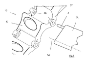
- FIG. 1 shows the frame of a radiator grille KG with two air passages LF.
- the air passage openings LF are associated with a number of closing elements in the form of each mounted on a pivot axis SA slats.
- the slats are in the FIG. 1 not shown.
- the individual pivot axes SA in the two air passage openings LF at an angle to each other.
- the pivot axes SA in the two air passages LF need not lie in a common plane.
- the two air passage openings LF - the associated levels - intersect in the direction of travel of the vehicle at an angle.
- the individual wear plates pivotally bearing bearing frame KG is arranged either directly in the radiator grille of the vehicle - on the design area of the radiator grille side facing away, or downstream in the body itself.
- the frame of the radiator grille KG has centrally a strut S separating the two air passage openings LF.
- this strut S the respective fin ends are pivotally mounted.
- a transmission element Ü is displaceably mounted.
- the transmission element Ü is connected to each of the closing slats SL via a pin Z arranged outside the pivot axis SA and pointing in the direction of the transmission element ( FIG. 3 ).
- the transmission element Ü is made as a one-piece plastic part and structurally composed of individual half-shell or U-shaped bodies K.
- the individual bodies K are each connected to each other by a pair of connecting webs ST, wherein each connecting web ST has in the center a spigot receptacle ZA as a joint element.
- the webs ST of the associated body K are designed to taper in the direction of the journal receptacle ZA, so that the respective journal receptacle ZA is flexurally elastic with respect to that formed by the body K. Is mounted transmission element.
- the described transmission element Ü is sufficiently pressure- or tension-resistant, but at the same time torsionally flexible and flexible.
- the transmission element Ü can thus act in a straight as well as a curved direction to displace, ie in particular on a strut S, which in accordance with FIG. 1 arcuate with respect to the plane of the drawing.
- the individual pin receivers ZA as articulated elements arranged between the bodies K are able to adapt to the closing elasticity SL (whose pin Z) is mounted perpendicularly to the extension direction of the transmission element Ü in accordance with the bending elasticity.
Landscapes
- Engineering & Computer Science (AREA)
- Mechanical Engineering (AREA)
- General Engineering & Computer Science (AREA)
- Chemical & Material Sciences (AREA)
- Combustion & Propulsion (AREA)
- Transportation (AREA)
- Cooling, Air Intake And Gas Exhaust, And Fuel Tank Arrangements In Propulsion Units (AREA)
- Arrangement And Mounting Of Devices That Control Transmission Of Motive Force (AREA)
- Gear-Shifting Mechanisms (AREA)
Abstract
Description
- Die Erfindung betrifft ein Übertragungselement für den steuerbaren Lufteinlass eines Kraftfahrzeuges nach der Art von Anspruch 1.
- In modernen Kraftfahrzeugen wird zur Verbesserung des Warmlauftverhaltens des Motors der Luftstrom zum Wärmetauscher mittels verstellbaren Elementen gesteuert. Bei den verstellbaren Elementen, den Schließelementen handelt es sich zumeist um eine Anzahl schwenkbar gelagerter Lamellen, wobei deren Schwenkachsen parallel oder, je nach Design des Kühlergrills unter einem Winkel zueinander orientiert und diese insgesamt in einem Rahmen schwenkbar angeordnet sind. Der Rahmen samt der Lamellenanordnung ist dem Kühlergrill nachgeordnet und dem Wärmetauscher des Motors vorgeordnet. Durch Schließen der Frischluftzufuhr während des Warmlaufens bzw. durch Steuern der Kühlluftmenge entsprechend der Motortemperatur wird die optimale Betriebstemperatur schneller erreicht bzw. kann innerhalb eines engen Temperaturbereiches gehalten werden.
- Beispiele für die beschriebenen Einrichtungen zeigen die
EP 2 233 341 A1 , dieEP 2 233 342 A1 , dieEP 2 325 035 A1 , dieDE 10 2008 049 010 A1 , dieDE 20 2005 010 683 U1 sowie dieDE 60 2004 007 338 T2 . - Die gezeigten Schließelemente sind als längliche Flächenelemente nach Art einer lamelle in im Wesentlichen ebener Form ausgebildet und um eine meist mittig durch das Flächenelement gehende Achse verschwenkbar. Der von der Luft zu durchströmenden Öffnung sind bei den bekannten Lösungen mehrere verschwenkbare Schließlamellen zugeordnet. Ein Beispiel für eine derartige Anordnung zeigt die
DE 10 2009 014 003 A1 . Die steuerbare Luftzufuhr dieser Lösung zeigt zwei nebeneinander liegende Öffnungen, wobei in jeder Öffnung drei um parallel zueinander angeordnete Achsen verschwenkbare Schließlamellen angeordnet sind. Die Ebenen der beiden Öffnungen schließen einen spitzen Winkel ein, d.h. die beiden Öffnungen liegen nicht in einer Ebene. Entsprechend verlaufen auch die Schwenkachsen der Schließlamellen in den beiden Öffnungen zueinander. - Beim der Einrichtung gemäß
EP 2 407 333 A1 ) ist ein Druck-Schubelement als Übertragungselement vorgesehen, welches der Verschwenkung einer Anzahl von verschwenkbar gelagerter Schließelementen dient. Jedes Schließelement ist mit einem außerhalb der Schwenkachse angeordneten Gelenkteil des Übertragungselementes verbunden. - Die
DE 10 2007 053 531 A1 zeigt eine als Rolloeinrichtung ausgebildete Abschaltung einer Luftzufuhr in einem Fahrzeug. Die einzelnen Schließelemente, Lamellen sind zu einer Kette, einem Rollo zusammengefügt, entsprechend gelenkig miteinander verbunden und in einer Führung geführt. Getrieben wird dieses Rollo durch eine Welle, welches ein Kettenrad aufweist. - Um die Schließlamellen in den beiden nebeneinander liegenden Öffnungen zu verstellen ist als Aktuator ein Betätigungselement vorgesehen, welches über einen Mechanismus auf die einzelnen Elemente gemeinsam einwirkt und so eine Gesamtverstellung der Schließelemente bewirkt.
- Die
DE 20 2005 010 683 U1 zeigt einen Lamellenvorhang, bestehend aus einer Anzahl einer Öffnung zugeordneter Lamellen, welche von einem Aktuator aus betätigt, verschwenkt werden. Als Übertragungselement der Betätigungsbewegung ist ein nicht näher beschriebenes Gestänge oder Zugmittel angegeben. - Die Aufgabe der vorliegenden Erfindung besteht darin, ein Übertragungselementgegenüber den bekannten Ausführungen verbesserter Ausführung zu schaffen.
- Diese Aufgabe wird gelöst durch die Merkmale von Anspruch 1. Weiterbildungen ergeben sich aus den Unteransprüchen.
- Gemäß der Erfindung ist ein Übertragungselement für den steuerbaren Lufteinlass eines Kraftfahrzeuges vorgesehen, welches der Erzeugung einer Schwenkbewegung einer Anzahl von angelenkten und schwenkbar gelagerten Schließelementen dient, wobei jedes Schließelement mit einem außerhalb der Schwenkachse angeordneten Gelenkteil mit einem Gelenkelement des Übertragungselementes verbunden ist, wobei das Übertragungselement als länglicher und zur Übertragung von Zug- und Schubkräften geeigneter Körper ausgebildet ist und die Gelenkelemente biegeelastisch gegenüber dem Körper angeordnet sind.
- Gemäß einer Ausführungsform der Erfindung ist ein einstückig und als Kunststoffformteil ausgeführtes Übertragungselement vorgesehen, welches sich aus einzelnen halbschalenförmigen Körpern zusammensetzt und in den biegeelastischen Verbindungsbereichen der einzelnen Körper die den Schließelementen zugeordneten Gelenkelemente aufweist.
- Gemäß einer Ausführungsform der Erfindung weisen die einzelnen Schließelemente je einen außerhalb der Schwenkachse und parallel zu dieser orientierten Gelenkzapfen auf, der in ein als Auge ausgebildetes Gelenkelement, eine Zapfenaufnahme des Übertragungselementes eingreift. Das Gelenkelement, die Zapfenaufnahme ist in dem Übergangsbereich der halbschalenförmigen Körper angeordnet. Vorzugsweise sind die halbschalenförmigen Körper über je ein Paar Stege miteinander verbunden und die Zapfenaufnahmen in diesem Übergangsbereich angeordnet.
- Mit dem erfindungsgemäßen Übertragungselement gelingt eine einfach ausführbare Übertragung der Betätigungskraft eines Aktuators auf eine Anzahl schwenkbar gelagerter Schließelemente. Das Übertragungselement ist dazu an einer Seite eines die Schließlamellen lagernden Rahmens angeordnet und verschiebbar gelagert. Die Schließlamellen weisen je einen außerhalb der Schwenkachse angeordneten Zapfen auf, der in je eine Gelenkaufnahme des Übertragungselementes eingreift. Eine Verschiebebewegung des Übertragungselementes erzeugt so eine gemeinsame Verschwenkbewegung der einzelnen Schleißlamellen.
- Durch die biegeelastische Anordnung der als Zapfenaufnahmen gestalteten Gelenkelemente ist es möglich, mit dem erfindungsgemäßen Übertragungselement auch Schließlamellen zu betätigen, der Schwenkachsen nicht parallel zueinander verlaufen.
- Insbesondere ist es möglich, bei einer steuerbaren Luftzufuhr mit zwei nebeneinander liegenden Luftzufuhröffnungen die den beiden Öffnungen zugeordneten Schließlamellen mit einem mittig angeordnetem Übertragungselement zu betätigen. Entsprechend weist das Übertragungselement beidseitig die biegeelastischen Gelenkelemente in Form der Zapfenaufnahmen auf.
- Des Weiteren erfolgt die Erläuterung eines Ausführungsbeispiels der Erfindung an Hand der Zeichnungen.
-
Figur 1 zeigt den Rahmen eines Kühlergrill KG mit zwei Luftdurchtrittsöffnungen LF. Den Luftdurchtrittsöffnungen LF sind eine Anzahl Schließelemente in Form von um je eine Schwenkachse SA gelagerter Lamellen zugeordnet. Die Lamellen sind in derFigur 1 nicht dargestellt. - Wie in
Figur 1 ersichtlich verlaufen die einzelnen Schwenkachsen SA in den beiden Luftdurchtrittsöffnungen LF unter einem Winkel zueinander. Insbesondere müssen die Schwenkachsen SA in den beiden Luftdurchtrittsöffnungen LF nicht in einer gemeinsamen Ebene liegen. Letztlich können die beiden Luftdurchtrittsöffnungen LF - die zugeordneten Ebenen - sich in Fahrtrichtung des Fahrzeuges in einem Winkel schneiden. Der die einzelnen Schleißlamellen schwenkbar lagernd tragende Rahmen KG ist dabei entweder direkt in dem Kühlergrill des Fahrzeuges angeordnet - auf der dem Designbereich der Kühlergrills abgewandten Seite, oder nachgeordnet in der Karosserie selbst. - Der Rahmen des Kühlergrills KG weist mittig einen die beiden Luftdurchtrittsöffnungen LF trennende Strebe S auf. In dieser Strebe S sind die entsprechenden Lamellenenden schwenkbar gelagert. In Erstreckungsrichtung dieser Strebe S ist ein Übertragungselement Ü verschiebbar gelagert. Das Übertragungselement Ü ist hierbei mit jedem der Schließlamellen SL über je einen außerhalb der Schwenkachse SA angeordneten und in Richtung Übertragungselement weisenden Zapfen Z verbunden (
Figur 3 ). - Das Übertragungselement Ü ist als ein einstückiges Kunststoffteil gefertigt und strukturell aus einzelnen halbschalen- bzw. U-förmigen Körpern K zusammengesetzt. Die einzelnen Körper K sind je durch ein Paar Verbindungsstege ST miteinander verbunden, wobei jeder Verbindungssteg ST mittig eine Zapfenaufnahme ZA als Gelenkelement aufweist. Die Stege ST des zugeordneten Körpers K sind in Richtung der Zapfenaufnahme ZA sich verjüngend gestaltet, so dass die jeweilige Zapfenaufnahme ZA biegeelastisch gegenüber dem durch die Körper K gebildeten Übertragungselement gelagert ist.
- Das beschriebene Übertragungselement Ü ist durch seine Gestaltung hinreichen druck- bzw. zugsteif, gleichzeitig aber torsions- und biegeweich. Das Übertragungselement Ü kann somit sowohl in einer geraden als auch eine gekrümmten Richtung verschiebend wirken, also insbesondere auf einer Strebe S, welche gemäß
Figur 1 bogenförmig gegenüber der Zeichnungsebene verläuft. Die einzelnen Zapfenaufnahmen ZA als zwischen den Körpern K angeordneten Gelenkelemente vermögen sich entsprechend der Biegeelastizität an auch nicht senkrecht zur Erstreckungsrichtung des Übertragungselementes Ü gelagerte Schließlamellen SL (deren Zapfen Z) anzupassen.Bezugszeichenliste KG Kühlergrill, Rahmen LF Luftdurchtrittsöffnung SA Schwenkachse (Schließelement, Schleißlamelle, Lamelle) S Strebe Ü Übertragungselement K Körper (Übertragungselement) ST Steg ZA Zapfenaufnahme Z Zapfen (Schließelement, Schleißlamelle, Lamelle) SL Schließelement, Schleißlamelle, Lamelle
Claims (3)
- Übertragungselement für den steuerbaren Lufteinlass eines Kraftfahrzeuges, wobei das Übertragungselement (Ü) der Erzeugung einer Schwenkbewegung einer Anzahl von angelenkten und schwenkbar gelagerten Schließelementen (SL) dient, wobei jedes Schließelement (SL) mit einem außerhalb der Schwenkachse angeordneten Gelenkteil (Z) mit einem Gelenkelement (ZA) des Übertragungselementes (Ü) verbunden ist, wobei das Übertragungselement (Ü) als länglicher und zur Übertragung von Zug- und Schubkräften geeigneter Körper (K) ausgebildet ist und die Gelenkelemente (ZA) biegeelastisch gegenüber diesem Körper (K) angeordnet sind, wobei das Übertragungselement (Ü) strukturell aus einer Anzahl von Körpern(K) zusammengesetzt ist, welche über sich verjüngende Stege (ST) miteinander verbunden sind, und wobei die Gelenkelemente (ZA) in dem als Steg (ST) ausgebildeten Verbindungsbereich zweier Körper (K) angeordnet sind.
- Übertragungselement nach Anspruch 1,
das Übertragungselement (Ü) ist als ein einstückiges Kunststoffteil gefertigt. - Übertragungselement nach einem der vorhergehenden Ansprüche,
das Gelenkelement (ZA) ist als eine Zapfenaufnahme für einen an dem Schließelement angebrachten Zapfen (Z) ausgebildet.
Applications Claiming Priority (1)
| Application Number | Priority Date | Filing Date | Title |
|---|---|---|---|
| DE102012011595.4A DE102012011595B4 (de) | 2012-06-13 | 2012-06-13 | Übertragungselement für einen steuerbaren Lufteinlass eines Kraftfahrzeugs |
Publications (3)
| Publication Number | Publication Date |
|---|---|
| EP2674314A2 true EP2674314A2 (de) | 2013-12-18 |
| EP2674314A3 EP2674314A3 (de) | 2017-03-29 |
| EP2674314B1 EP2674314B1 (de) | 2018-05-30 |
Family
ID=48326109
Family Applications (1)
| Application Number | Title | Priority Date | Filing Date |
|---|---|---|---|
| EP13165408.9A Not-in-force EP2674314B1 (de) | 2012-06-13 | 2013-04-25 | Übertragungselement für ein Kraftfahrzeug |
Country Status (5)
| Country | Link |
|---|---|
| US (1) | US11473655B2 (de) |
| EP (1) | EP2674314B1 (de) |
| CN (1) | CN103481769B (de) |
| DE (1) | DE102012011595B4 (de) |
| MX (1) | MX352190B (de) |
Cited By (1)
| Publication number | Priority date | Publication date | Assignee | Title |
|---|---|---|---|---|
| EP3476640A1 (de) * | 2017-10-27 | 2019-05-01 | REHAU AG + Co | Einrichtung für einen frontstossfänger eines kraftfahrzeugs |
Families Citing this family (7)
| Publication number | Priority date | Publication date | Assignee | Title |
|---|---|---|---|---|
| FR3040663B1 (fr) * | 2015-09-07 | 2017-09-29 | Plastic Omnium Cie | Volets d'entree d'air affleurants |
| FR3067296B1 (fr) * | 2017-06-13 | 2020-01-10 | Compagnie Plastic Omnium | Systeme aerodynamique actif avec actionneur deporte |
| JP6922654B2 (ja) * | 2017-10-27 | 2021-08-18 | 豊田合成株式会社 | 車両用グリルシャッタ装置 |
| IT201900004187A1 (it) * | 2019-03-22 | 2020-09-22 | Automobili Lamborghini Spa | Dispositivo di regolazione di un flusso di aria di raffreddamento in un veicolo. |
| DE102019117986B4 (de) * | 2019-07-03 | 2021-06-24 | Hbpo Gmbh | Vorrichtung zum Verschließen eines Kraftfahrzeugkühlmoduls |
| DE102020131530B3 (de) * | 2020-11-27 | 2021-10-14 | Montaplast Gesellschaft mit beschränkter Haftung | Luftführungssteuerung |
| DE102022124179A1 (de) * | 2022-09-21 | 2024-03-21 | Dr. Ing. H.C. F. Porsche Aktiengesellschaft | Luftleitvorrichtung einer Kraftfahrzeugkarosserie eines Kraftfahrzeugs |
Citations (9)
| Publication number | Priority date | Publication date | Assignee | Title |
|---|---|---|---|---|
| DE202005010683U1 (de) | 2005-07-06 | 2005-09-15 | Festo Ag & Co | Vorrichtung zur Steuerung der Luftzuströmung bei Kraftfahrzeugen |
| DE602004007338T2 (de) | 2003-10-06 | 2008-03-06 | Peugeot Citroën Automobiles S.A. | Vorrichtung zur Regulierung eines insbesondere unter die Motorhaube eines Kraftfahrzeuges eintretenden Luftstromes |
| DE102007053531A1 (de) | 2007-11-09 | 2009-05-20 | Hs Genion Gmbh | Rolloeinrichtung |
| DE102008049010A1 (de) | 2008-09-25 | 2010-04-01 | Dr.Ing.H.C.F.Porsche Aktiengesellschaft | Vorrichtung zur Zuführung von Kühlluft zu einem Fahrzeugkühler eines Kraftfahrzeugs |
| DE102009014003A1 (de) | 2009-03-19 | 2010-09-23 | GM Global Technology Operations, Inc., Detroit | Kühlluftzufuhreinrichtung für einen Verbrennungsmotor mit einer Notbetätigungseinrichtung |
| EP2233342A1 (de) | 2009-03-25 | 2010-09-29 | Aisin Seiki Kabushiki Kaisha | Unité de commande pour élément mobile |
| EP2233341A1 (de) | 2009-03-25 | 2010-09-29 | Aisin Seiki Kabushiki Kaisha | Unité de commande pour élément mobile |
| EP2325035A1 (de) | 2009-11-19 | 2011-05-25 | Aisin Seiki Kabushiki Kaisha | Grillsteuerungsmechanismus für Fahrzeug |
| EP2407333A1 (de) | 2010-07-13 | 2012-01-18 | Aisin Seiki Kabushiki Kaisha | Bewegliche Grillblendenvorrichtung für ein Fahrzeug |
Family Cites Families (14)
| Publication number | Priority date | Publication date | Assignee | Title |
|---|---|---|---|---|
| US1699020A (en) * | 1925-11-05 | 1929-01-15 | Pines Winter Front Company | Shutter apparatus for radiators |
| US1798503A (en) * | 1928-08-01 | 1931-03-31 | Emanuel M Stern | Means for operating ventilators on automobiles |
| JPS5968126U (ja) * | 1982-10-29 | 1984-05-09 | 日野自動車株式会社 | 自動車のフロントグリル |
| EP0141805A3 (de) * | 1983-10-25 | 1986-01-22 | Günther Erber | Rolladen |
| US4753288A (en) * | 1986-10-22 | 1988-06-28 | Kysor Industrial Corporation | Polymeric shutter assembly |
| DE19602186C1 (de) * | 1996-01-23 | 1997-05-22 | Porsche Ag | Kraftfahrzeug mit einer bugseitigen Kühleranordnung |
| KR100189257B1 (ko) * | 1996-06-11 | 1999-06-01 | 정몽규 | 차량의 라디에이터 그릴 가변 장치 |
| US7866737B2 (en) * | 2007-01-31 | 2011-01-11 | Gm Global Technology Operations, Inc. | Active material actuated louver system |
| DE102008013422A1 (de) * | 2008-03-10 | 2009-09-17 | Röchling Automotive AG & Co. KG | Antriebssystem für aktive Luftklappensteuerung |
| DE102008061054A1 (de) * | 2008-12-08 | 2010-06-17 | Röchling Automotive AG & Co. KG | Luftklappenantrieb |
| DE102008064513A1 (de) * | 2008-12-22 | 2010-06-24 | Veritas Ag | Verstellbare Kühlergrillanordnung |
| US8646552B2 (en) * | 2010-07-21 | 2014-02-11 | Shape Corp. | Integrated energy absorber and air flow management structure |
| CA2758502C (en) * | 2010-11-16 | 2018-09-25 | Magna International Inc. | Bracket - active grille and actuator |
| US9250020B2 (en) * | 2011-01-05 | 2016-02-02 | Tesla Motors, Inc. | Active louver system for controlled airflow in a multi-function automotive radiator and condenser system |
-
2012
- 2012-06-13 DE DE102012011595.4A patent/DE102012011595B4/de not_active Expired - Fee Related
-
2013
- 2013-04-25 EP EP13165408.9A patent/EP2674314B1/de not_active Not-in-force
- 2013-06-05 CN CN201310220525.1A patent/CN103481769B/zh not_active Expired - Fee Related
- 2013-06-13 MX MX2013006778A patent/MX352190B/es active IP Right Grant
- 2013-06-13 US US13/916,995 patent/US11473655B2/en active Active
Patent Citations (9)
| Publication number | Priority date | Publication date | Assignee | Title |
|---|---|---|---|---|
| DE602004007338T2 (de) | 2003-10-06 | 2008-03-06 | Peugeot Citroën Automobiles S.A. | Vorrichtung zur Regulierung eines insbesondere unter die Motorhaube eines Kraftfahrzeuges eintretenden Luftstromes |
| DE202005010683U1 (de) | 2005-07-06 | 2005-09-15 | Festo Ag & Co | Vorrichtung zur Steuerung der Luftzuströmung bei Kraftfahrzeugen |
| DE102007053531A1 (de) | 2007-11-09 | 2009-05-20 | Hs Genion Gmbh | Rolloeinrichtung |
| DE102008049010A1 (de) | 2008-09-25 | 2010-04-01 | Dr.Ing.H.C.F.Porsche Aktiengesellschaft | Vorrichtung zur Zuführung von Kühlluft zu einem Fahrzeugkühler eines Kraftfahrzeugs |
| DE102009014003A1 (de) | 2009-03-19 | 2010-09-23 | GM Global Technology Operations, Inc., Detroit | Kühlluftzufuhreinrichtung für einen Verbrennungsmotor mit einer Notbetätigungseinrichtung |
| EP2233342A1 (de) | 2009-03-25 | 2010-09-29 | Aisin Seiki Kabushiki Kaisha | Unité de commande pour élément mobile |
| EP2233341A1 (de) | 2009-03-25 | 2010-09-29 | Aisin Seiki Kabushiki Kaisha | Unité de commande pour élément mobile |
| EP2325035A1 (de) | 2009-11-19 | 2011-05-25 | Aisin Seiki Kabushiki Kaisha | Grillsteuerungsmechanismus für Fahrzeug |
| EP2407333A1 (de) | 2010-07-13 | 2012-01-18 | Aisin Seiki Kabushiki Kaisha | Bewegliche Grillblendenvorrichtung für ein Fahrzeug |
Cited By (1)
| Publication number | Priority date | Publication date | Assignee | Title |
|---|---|---|---|---|
| EP3476640A1 (de) * | 2017-10-27 | 2019-05-01 | REHAU AG + Co | Einrichtung für einen frontstossfänger eines kraftfahrzeugs |
Also Published As
| Publication number | Publication date |
|---|---|
| US11473655B2 (en) | 2022-10-18 |
| EP2674314A3 (de) | 2017-03-29 |
| DE102012011595B4 (de) | 2016-09-15 |
| MX2013006778A (es) | 2014-03-21 |
| CN103481769A (zh) | 2014-01-01 |
| MX352190B (es) | 2017-11-10 |
| CN103481769B (zh) | 2016-08-10 |
| EP2674314B1 (de) | 2018-05-30 |
| US20130333501A1 (en) | 2013-12-19 |
| DE102012011595A1 (de) | 2013-12-19 |
Similar Documents
| Publication | Publication Date | Title |
|---|---|---|
| EP2674314B1 (de) | Übertragungselement für ein Kraftfahrzeug | |
| EP3227134B1 (de) | Luftregelsystem für fahrzeuge mit montageverfahren | |
| DE3438709C1 (de) | Kuehlerjalousie | |
| DE102010038194A1 (de) | Verstellbare Leitvorrichtung | |
| DE2153743C3 (de) | Luftdüse für eine Belüftungsanlage | |
| DE102011089265A1 (de) | Luftzufuhreinstellvorrichtung | |
| EP1469272A2 (de) | Wärmeübertrageranordnung für Kraftfahrzeuge | |
| DE102014108575A1 (de) | Kühlerjalousieanordnung | |
| DE102012011594A1 (de) | Steuerbarer Lufteinlass für ein Kraftfahrzeug | |
| DE102016007369A1 (de) | Kühlerjalousie für ein Kraftfahrzeug | |
| DE102016209156A1 (de) | Klappen-System für die Regelung einer Fahrzeugkühlung | |
| DE102017119098A1 (de) | Innenliegende Antriebswelle | |
| DE102012214474B4 (de) | Steuerbarer Lufteinlass für ein Kraftfahrzeug | |
| EP1270286B1 (de) | Luftleitvorrichtung, insbesondere eines Fahrzeugs | |
| DE102005027746A1 (de) | Luftausströmer für den Fahrgastraum eines Fahrzeuges | |
| EP3530505A1 (de) | Luftausströmer | |
| WO2020234031A1 (de) | Luftauslasseinheit für eine fahrzeuglüftung und fahrzeug | |
| DE102015012965A1 (de) | Vorrichtung zur Regulierung eines Luftstroms | |
| DE102019206739A1 (de) | Luftausströmer mit einer Luftregelklappe und einer Torsionsfeder | |
| EP2602137A2 (de) | Luftauslassvorrichtung für den Innenraum eines Fahrzeugs | |
| DE102016122138A1 (de) | Luftausströmer | |
| DE102017120631A1 (de) | Vorrichtung zum Regulieren einer Luftströmung | |
| EP0841202B1 (de) | Heiz- oder Klimaanlage | |
| EP2050598B1 (de) | Klappenanordnung, für eine Fahrzeug-Klimaanlage | |
| DE102017102164A1 (de) | Luftregeleinrichtung für ein Kraftfahrzeug |
Legal Events
| Date | Code | Title | Description |
|---|---|---|---|
| PUAI | Public reference made under article 153(3) epc to a published international application that has entered the european phase |
Free format text: ORIGINAL CODE: 0009012 |
|
| AK | Designated contracting states |
Kind code of ref document: A2 Designated state(s): AL AT BE BG CH CY CZ DE DK EE ES FI FR GB GR HR HU IE IS IT LI LT LU LV MC MK MT NL NO PL PT RO RS SE SI SK SM TR |
|
| AX | Request for extension of the european patent |
Extension state: BA ME |
|
| PUAL | Search report despatched |
Free format text: ORIGINAL CODE: 0009013 |
|
| STAA | Information on the status of an ep patent application or granted ep patent |
Free format text: STATUS: REQUEST FOR EXAMINATION WAS MADE |
|
| AK | Designated contracting states |
Kind code of ref document: A3 Designated state(s): AL AT BE BG CH CY CZ DE DK EE ES FI FR GB GR HR HU IE IS IT LI LT LU LV MC MK MT NL NO PL PT RO RS SE SI SK SM TR |
|
| AX | Request for extension of the european patent |
Extension state: BA ME |
|
| RAP1 | Party data changed (applicant data changed or rights of an application transferred) |
Owner name: MAGNA EXTERIORS (GERMANY) GMBH |
|
| RIC1 | Information provided on ipc code assigned before grant |
Ipc: F16H 21/10 20060101ALI20170218BHEP Ipc: B60K 11/08 20060101AFI20170218BHEP Ipc: F01P 7/10 20060101ALI20170218BHEP Ipc: F16H 21/44 20060101ALI20170218BHEP |
|
| 17P | Request for examination filed |
Effective date: 20170227 |
|
| RBV | Designated contracting states (corrected) |
Designated state(s): AL AT BE BG CH CY CZ DE DK EE ES FI FR GB GR HR HU IE IS IT LI LT LU LV MC MK MT NL NO PL PT RO RS SE SI SK SM TR |
|
| GRAP | Despatch of communication of intention to grant a patent |
Free format text: ORIGINAL CODE: EPIDOSNIGR1 |
|
| STAA | Information on the status of an ep patent application or granted ep patent |
Free format text: STATUS: GRANT OF PATENT IS INTENDED |
|
| INTG | Intention to grant announced |
Effective date: 20180119 |
|
| GRAS | Grant fee paid |
Free format text: ORIGINAL CODE: EPIDOSNIGR3 |
|
| GRAA | (expected) grant |
Free format text: ORIGINAL CODE: 0009210 |
|
| STAA | Information on the status of an ep patent application or granted ep patent |
Free format text: STATUS: THE PATENT HAS BEEN GRANTED |
|
| AK | Designated contracting states |
Kind code of ref document: B1 Designated state(s): AL AT BE BG CH CY CZ DE DK EE ES FI FR GB GR HR HU IE IS IT LI LT LU LV MC MK MT NL NO PL PT RO RS SE SI SK SM TR |
|
| REG | Reference to a national code |
Ref country code: GB Ref legal event code: FG4D Free format text: NOT ENGLISH |
|
| REG | Reference to a national code |
Ref country code: CH Ref legal event code: EP |
|
| REG | Reference to a national code |
Ref country code: AT Ref legal event code: REF Ref document number: 1003249 Country of ref document: AT Kind code of ref document: T Effective date: 20180615 |
|
| REG | Reference to a national code |
Ref country code: IE Ref legal event code: FG4D Free format text: LANGUAGE OF EP DOCUMENT: GERMAN |
|
| REG | Reference to a national code |
Ref country code: DE Ref legal event code: R096 Ref document number: 502013010231 Country of ref document: DE |
|
| REG | Reference to a national code |
Ref country code: NL Ref legal event code: MP Effective date: 20180530 |
|
| REG | Reference to a national code |
Ref country code: LT Ref legal event code: MG4D |
|
| PG25 | Lapsed in a contracting state [announced via postgrant information from national office to epo] |
Ref country code: ES Free format text: LAPSE BECAUSE OF FAILURE TO SUBMIT A TRANSLATION OF THE DESCRIPTION OR TO PAY THE FEE WITHIN THE PRESCRIBED TIME-LIMIT Effective date: 20180530 Ref country code: SE Free format text: LAPSE BECAUSE OF FAILURE TO SUBMIT A TRANSLATION OF THE DESCRIPTION OR TO PAY THE FEE WITHIN THE PRESCRIBED TIME-LIMIT Effective date: 20180530 Ref country code: NO Free format text: LAPSE BECAUSE OF FAILURE TO SUBMIT A TRANSLATION OF THE DESCRIPTION OR TO PAY THE FEE WITHIN THE PRESCRIBED TIME-LIMIT Effective date: 20180830 Ref country code: BG Free format text: LAPSE BECAUSE OF FAILURE TO SUBMIT A TRANSLATION OF THE DESCRIPTION OR TO PAY THE FEE WITHIN THE PRESCRIBED TIME-LIMIT Effective date: 20180830 Ref country code: FI Free format text: LAPSE BECAUSE OF FAILURE TO SUBMIT A TRANSLATION OF THE DESCRIPTION OR TO PAY THE FEE WITHIN THE PRESCRIBED TIME-LIMIT Effective date: 20180530 Ref country code: LT Free format text: LAPSE BECAUSE OF FAILURE TO SUBMIT A TRANSLATION OF THE DESCRIPTION OR TO PAY THE FEE WITHIN THE PRESCRIBED TIME-LIMIT Effective date: 20180530 Ref country code: CY Free format text: LAPSE BECAUSE OF FAILURE TO SUBMIT A TRANSLATION OF THE DESCRIPTION OR TO PAY THE FEE WITHIN THE PRESCRIBED TIME-LIMIT Effective date: 20180530 |
|
| PG25 | Lapsed in a contracting state [announced via postgrant information from national office to epo] |
Ref country code: GR Free format text: LAPSE BECAUSE OF FAILURE TO SUBMIT A TRANSLATION OF THE DESCRIPTION OR TO PAY THE FEE WITHIN THE PRESCRIBED TIME-LIMIT Effective date: 20180831 Ref country code: RS Free format text: LAPSE BECAUSE OF FAILURE TO SUBMIT A TRANSLATION OF THE DESCRIPTION OR TO PAY THE FEE WITHIN THE PRESCRIBED TIME-LIMIT Effective date: 20180530 Ref country code: HR Free format text: LAPSE BECAUSE OF FAILURE TO SUBMIT A TRANSLATION OF THE DESCRIPTION OR TO PAY THE FEE WITHIN THE PRESCRIBED TIME-LIMIT Effective date: 20180530 Ref country code: LV Free format text: LAPSE BECAUSE OF FAILURE TO SUBMIT A TRANSLATION OF THE DESCRIPTION OR TO PAY THE FEE WITHIN THE PRESCRIBED TIME-LIMIT Effective date: 20180530 |
|
| PG25 | Lapsed in a contracting state [announced via postgrant information from national office to epo] |
Ref country code: NL Free format text: LAPSE BECAUSE OF FAILURE TO SUBMIT A TRANSLATION OF THE DESCRIPTION OR TO PAY THE FEE WITHIN THE PRESCRIBED TIME-LIMIT Effective date: 20180530 |
|
| PG25 | Lapsed in a contracting state [announced via postgrant information from national office to epo] |
Ref country code: CZ Free format text: LAPSE BECAUSE OF FAILURE TO SUBMIT A TRANSLATION OF THE DESCRIPTION OR TO PAY THE FEE WITHIN THE PRESCRIBED TIME-LIMIT Effective date: 20180530 Ref country code: RO Free format text: LAPSE BECAUSE OF FAILURE TO SUBMIT A TRANSLATION OF THE DESCRIPTION OR TO PAY THE FEE WITHIN THE PRESCRIBED TIME-LIMIT Effective date: 20180530 Ref country code: SK Free format text: LAPSE BECAUSE OF FAILURE TO SUBMIT A TRANSLATION OF THE DESCRIPTION OR TO PAY THE FEE WITHIN THE PRESCRIBED TIME-LIMIT Effective date: 20180530 Ref country code: DK Free format text: LAPSE BECAUSE OF FAILURE TO SUBMIT A TRANSLATION OF THE DESCRIPTION OR TO PAY THE FEE WITHIN THE PRESCRIBED TIME-LIMIT Effective date: 20180530 Ref country code: PL Free format text: LAPSE BECAUSE OF FAILURE TO SUBMIT A TRANSLATION OF THE DESCRIPTION OR TO PAY THE FEE WITHIN THE PRESCRIBED TIME-LIMIT Effective date: 20180530 Ref country code: EE Free format text: LAPSE BECAUSE OF FAILURE TO SUBMIT A TRANSLATION OF THE DESCRIPTION OR TO PAY THE FEE WITHIN THE PRESCRIBED TIME-LIMIT Effective date: 20180530 |
|
| PG25 | Lapsed in a contracting state [announced via postgrant information from national office to epo] |
Ref country code: IT Free format text: LAPSE BECAUSE OF FAILURE TO SUBMIT A TRANSLATION OF THE DESCRIPTION OR TO PAY THE FEE WITHIN THE PRESCRIBED TIME-LIMIT Effective date: 20180530 Ref country code: SM Free format text: LAPSE BECAUSE OF FAILURE TO SUBMIT A TRANSLATION OF THE DESCRIPTION OR TO PAY THE FEE WITHIN THE PRESCRIBED TIME-LIMIT Effective date: 20180530 |
|
| REG | Reference to a national code |
Ref country code: DE Ref legal event code: R097 Ref document number: 502013010231 Country of ref document: DE |
|
| PLBE | No opposition filed within time limit |
Free format text: ORIGINAL CODE: 0009261 |
|
| STAA | Information on the status of an ep patent application or granted ep patent |
Free format text: STATUS: NO OPPOSITION FILED WITHIN TIME LIMIT |
|
| 26N | No opposition filed |
Effective date: 20190301 |
|
| PG25 | Lapsed in a contracting state [announced via postgrant information from national office to epo] |
Ref country code: SI Free format text: LAPSE BECAUSE OF FAILURE TO SUBMIT A TRANSLATION OF THE DESCRIPTION OR TO PAY THE FEE WITHIN THE PRESCRIBED TIME-LIMIT Effective date: 20180530 |
|
| PG25 | Lapsed in a contracting state [announced via postgrant information from national office to epo] |
Ref country code: AL Free format text: LAPSE BECAUSE OF FAILURE TO SUBMIT A TRANSLATION OF THE DESCRIPTION OR TO PAY THE FEE WITHIN THE PRESCRIBED TIME-LIMIT Effective date: 20180530 |
|
| REG | Reference to a national code |
Ref country code: CH Ref legal event code: PL |
|
| REG | Reference to a national code |
Ref country code: BE Ref legal event code: MM Effective date: 20190430 |
|
| PG25 | Lapsed in a contracting state [announced via postgrant information from national office to epo] |
Ref country code: MC Free format text: LAPSE BECAUSE OF FAILURE TO SUBMIT A TRANSLATION OF THE DESCRIPTION OR TO PAY THE FEE WITHIN THE PRESCRIBED TIME-LIMIT Effective date: 20180530 Ref country code: LU Free format text: LAPSE BECAUSE OF NON-PAYMENT OF DUE FEES Effective date: 20190425 |
|
| PG25 | Lapsed in a contracting state [announced via postgrant information from national office to epo] |
Ref country code: CH Free format text: LAPSE BECAUSE OF NON-PAYMENT OF DUE FEES Effective date: 20190430 Ref country code: LI Free format text: LAPSE BECAUSE OF NON-PAYMENT OF DUE FEES Effective date: 20190430 |
|
| PG25 | Lapsed in a contracting state [announced via postgrant information from national office to epo] |
Ref country code: BE Free format text: LAPSE BECAUSE OF NON-PAYMENT OF DUE FEES Effective date: 20190430 |
|
| PG25 | Lapsed in a contracting state [announced via postgrant information from national office to epo] |
Ref country code: TR Free format text: LAPSE BECAUSE OF FAILURE TO SUBMIT A TRANSLATION OF THE DESCRIPTION OR TO PAY THE FEE WITHIN THE PRESCRIBED TIME-LIMIT Effective date: 20180530 |
|
| PG25 | Lapsed in a contracting state [announced via postgrant information from national office to epo] |
Ref country code: IE Free format text: LAPSE BECAUSE OF NON-PAYMENT OF DUE FEES Effective date: 20190425 |
|
| PG25 | Lapsed in a contracting state [announced via postgrant information from national office to epo] |
Ref country code: PT Free format text: LAPSE BECAUSE OF FAILURE TO SUBMIT A TRANSLATION OF THE DESCRIPTION OR TO PAY THE FEE WITHIN THE PRESCRIBED TIME-LIMIT Effective date: 20181001 |
|
| REG | Reference to a national code |
Ref country code: AT Ref legal event code: MM01 Ref document number: 1003249 Country of ref document: AT Kind code of ref document: T Effective date: 20190425 |
|
| PG25 | Lapsed in a contracting state [announced via postgrant information from national office to epo] |
Ref country code: AT Free format text: LAPSE BECAUSE OF NON-PAYMENT OF DUE FEES Effective date: 20190425 |
|
| PG25 | Lapsed in a contracting state [announced via postgrant information from national office to epo] |
Ref country code: IS Free format text: LAPSE BECAUSE OF FAILURE TO SUBMIT A TRANSLATION OF THE DESCRIPTION OR TO PAY THE FEE WITHIN THE PRESCRIBED TIME-LIMIT Effective date: 20180930 |
|
| PG25 | Lapsed in a contracting state [announced via postgrant information from national office to epo] |
Ref country code: HU Free format text: LAPSE BECAUSE OF FAILURE TO SUBMIT A TRANSLATION OF THE DESCRIPTION OR TO PAY THE FEE WITHIN THE PRESCRIBED TIME-LIMIT; INVALID AB INITIO Effective date: 20130425 Ref country code: MT Free format text: LAPSE BECAUSE OF FAILURE TO SUBMIT A TRANSLATION OF THE DESCRIPTION OR TO PAY THE FEE WITHIN THE PRESCRIBED TIME-LIMIT Effective date: 20180530 |
|
| PG25 | Lapsed in a contracting state [announced via postgrant information from national office to epo] |
Ref country code: MK Free format text: LAPSE BECAUSE OF FAILURE TO SUBMIT A TRANSLATION OF THE DESCRIPTION OR TO PAY THE FEE WITHIN THE PRESCRIBED TIME-LIMIT Effective date: 20180530 |
|
| PGFP | Annual fee paid to national office [announced via postgrant information from national office to epo] |
Ref country code: GB Payment date: 20220425 Year of fee payment: 10 Ref country code: FR Payment date: 20220421 Year of fee payment: 10 Ref country code: DE Payment date: 20220420 Year of fee payment: 10 |
|
| REG | Reference to a national code |
Ref country code: DE Ref legal event code: R119 Ref document number: 502013010231 Country of ref document: DE |
|
| GBPC | Gb: european patent ceased through non-payment of renewal fee |
Effective date: 20230425 |
|
| PG25 | Lapsed in a contracting state [announced via postgrant information from national office to epo] |
Ref country code: GB Free format text: LAPSE BECAUSE OF NON-PAYMENT OF DUE FEES Effective date: 20230425 |
|
| PG25 | Lapsed in a contracting state [announced via postgrant information from national office to epo] |
Ref country code: GB Free format text: LAPSE BECAUSE OF NON-PAYMENT OF DUE FEES Effective date: 20230425 Ref country code: FR Free format text: LAPSE BECAUSE OF NON-PAYMENT OF DUE FEES Effective date: 20230430 Ref country code: DE Free format text: LAPSE BECAUSE OF NON-PAYMENT OF DUE FEES Effective date: 20231103 |