EP2674098A1 - Schaft für ein flexibles Endoskop oder ein flexibles endoskopisches Instrument - Google Patents
Schaft für ein flexibles Endoskop oder ein flexibles endoskopisches Instrument Download PDFInfo
- Publication number
- EP2674098A1 EP2674098A1 EP13170870.3A EP13170870A EP2674098A1 EP 2674098 A1 EP2674098 A1 EP 2674098A1 EP 13170870 A EP13170870 A EP 13170870A EP 2674098 A1 EP2674098 A1 EP 2674098A1
- Authority
- EP
- European Patent Office
- Prior art keywords
- shaft
- flexible
- endoscope
- torsion
- traction means
- Prior art date
- Legal status (The legal status is an assumption and is not a legal conclusion. Google has not performed a legal analysis and makes no representation as to the accuracy of the status listed.)
- Granted
Links
Images
Classifications
-
- A—HUMAN NECESSITIES
- A61—MEDICAL OR VETERINARY SCIENCE; HYGIENE
- A61B—DIAGNOSIS; SURGERY; IDENTIFICATION
- A61B1/00—Instruments for performing medical examinations of the interior of cavities or tubes of the body by visual or photographical inspection, e.g. endoscopes; Illuminating arrangements therefor
- A61B1/005—Flexible endoscopes
- A61B1/0051—Flexible endoscopes with controlled bending of insertion part
- A61B1/0057—Constructional details of force transmission elements, e.g. control wires
-
- A—HUMAN NECESSITIES
- A61—MEDICAL OR VETERINARY SCIENCE; HYGIENE
- A61B—DIAGNOSIS; SURGERY; IDENTIFICATION
- A61B1/00—Instruments for performing medical examinations of the interior of cavities or tubes of the body by visual or photographical inspection, e.g. endoscopes; Illuminating arrangements therefor
- A61B1/00147—Holding or positioning arrangements
- A61B1/0016—Holding or positioning arrangements using motor drive units
-
- A—HUMAN NECESSITIES
- A61—MEDICAL OR VETERINARY SCIENCE; HYGIENE
- A61B—DIAGNOSIS; SURGERY; IDENTIFICATION
- A61B1/00—Instruments for performing medical examinations of the interior of cavities or tubes of the body by visual or photographical inspection, e.g. endoscopes; Illuminating arrangements therefor
- A61B1/005—Flexible endoscopes
- A61B1/0051—Flexible endoscopes with controlled bending of insertion part
- A61B1/0052—Constructional details of control elements, e.g. handles
-
- A—HUMAN NECESSITIES
- A61—MEDICAL OR VETERINARY SCIENCE; HYGIENE
- A61B—DIAGNOSIS; SURGERY; IDENTIFICATION
- A61B17/00—Surgical instruments, devices or methods
- A61B17/00234—Surgical instruments, devices or methods for minimally invasive surgery
-
- F—MECHANICAL ENGINEERING; LIGHTING; HEATING; WEAPONS; BLASTING
- F16—ENGINEERING ELEMENTS AND UNITS; GENERAL MEASURES FOR PRODUCING AND MAINTAINING EFFECTIVE FUNCTIONING OF MACHINES OR INSTALLATIONS; THERMAL INSULATION IN GENERAL
- F16H—GEARING
- F16H19/00—Gearings comprising essentially only toothed gears or friction members and not capable of conveying indefinitely-continuing rotary motion
- F16H19/02—Gearings comprising essentially only toothed gears or friction members and not capable of conveying indefinitely-continuing rotary motion for interconverting rotary or oscillating motion and reciprocating motion
- F16H19/06—Gearings comprising essentially only toothed gears or friction members and not capable of conveying indefinitely-continuing rotary motion for interconverting rotary or oscillating motion and reciprocating motion comprising flexible members, e.g. an endless flexible member
- F16H19/0654—Gearings comprising essentially only toothed gears or friction members and not capable of conveying indefinitely-continuing rotary motion for interconverting rotary or oscillating motion and reciprocating motion comprising flexible members, e.g. an endless flexible member using twisting movement of flexible members to modify the axial length of the mechanism
Definitions
- the present invention relates to a shaft for a flexible endoscope or for a flexible endoscopic instrument according to the preamble of claim 1 and to a flexible endoscope and a flexible endoscopic instrument with such a shaft.
- Flexible endoscopes are used for a variety of medical and technical applications.
- Such flexible endoscopes include a flexible elongated shaft suitable for insertion into a cavity such as a body cavity or a technical object cavity.
- a cavity such as a body cavity or a technical object cavity.
- an endoscope objective for generating an image of a scene in the observed cavity is arranged at the tip of the endoscope shaft.
- an ordered bundle of optical fibers extending within the shaft may be provided, or an electronic imaging device such as a CCD chip located in the region is disposed at the distal end of the shaft, and its signals are transmitted to the proximal end portion via electrical leads extending within the shaft.
- a light guide system may also be provided within the shaft be arranged to transport light to the distal end of the endoscope, where it is used to illuminate the cavity.
- the endoscope shaft can contain one or more working channels for the passage of endoscopic working instruments from the proximal to the distal end region of the shaft, with the aid of which manipulations can be carried out within the cavity.
- Endoscopic instruments which include a flexible elongated shaft which is also suitable for insertion into a cavity, such as a body cavity or cavity of a technical object.
- a flexible endoscopic instrument can be used for performing manipulations in the cavity and, for this purpose, for example, be designed as a barrel instrument for grasping and manipulating tissue or objects in the body-internal cavity or in the cavity of a technical object.
- a tool is arranged at the distal end of the flexible shaft, which can be operated via a running within the shaft transmission means from the proximal end of the shaft forth.
- such a flexible endoscopic instrument does not have its own optics for receiving an endoscopic image, but it can in particular be used together with a flexible endoscope.
- the shaft has a controllable section, in particular a controllable end section, which is actively angled in the desired direction by a desired amount and for this purpose can be controlled from the proximal end of the endoscope or the endoscopic instrument.
- the shaft for a flexible endoscopic instrument does not itself have a tool and a transmission means, but may for example comprise a working channel, in which a flexible endoscopic working tool, which is not actively bendable and having such a tool, can be inserted to the distal end of the shaft and possibly beyond, so that the flexible working instrument can be angled with the help of the shaft.
- each segment of a controllable portion of the endoscope shaft is pivotally mounted relative to the next or preceding segment.
- four cables are provided, which are guided by a proximally arranged control device to the endoscope tip.
- the cables run in the edge region of the segments and are each offset by 90 ° with respect to a longitudinal axis, so that a control of the endoscope tip can be effected in a desired direction by rolling up the corresponding ropes in the control device.
- Adjusting devices for adjusting the tension of the cables are for example off DE 29 14 748 C2 and US 4,203,430 known; However, such adjusting devices are associated with increased design and operating costs.
- the required permanent tension of the cables can also lead to a shortening of the shaft, which can adversely affect the controllability of the endoscope tip and in general the properties of the endoscope shaft, such as the flexibility or the surface condition.
- the achievable bend also depends on the curvature of the entire shaft portion through which the cables are guided, so that no clear relationship between the position of a handwheel with which a cable can be rolled up, and the deflection angle achieved the endoscope tip exists. Curvatures of the endoscope also cause increased friction of the cables, which also makes the operation of the bending more difficult. Finally, the cables, especially for longer shafts, tear due to friction and wear.
- JP 07134253 A discloses an endoscope with a bendable portion comprising a plurality of hingedly interconnected segments having threaded nuts cooperating with bolts connected to a flexible shaft.
- a micromotor is disposed in the shaft of the endoscope, which rotates the flexible shaft for controlling a bend of the bendable portion.
- This is associated with a relatively high design effort.
- the load capacity of the shaft with the associated threaded nuts and in particular the resilience of the thread with small shank diameters is not always sufficient.
- the arrangement of a micromotor in a small diameter endoscope shaft, within which further lines or channels extend not readily possible and also for reasons of accessibility of the engine for repair and maintenance purposes and possibly for cleaning and sterilization with great effort connected.
- an inventive shaft for a flexible endoscope or for a flexible endoscopic instrument is elongated and for insertion into a cavity, for example a body-internal cavity or a cavity of a technical object formed.
- the flexible endoscope may comprise a handle arranged at a proximal end of the shaft, which may have operating elements and / or connections for further devices, such as a suction and rinsing device, a light source or a camera unit.
- the handle can also contain a camera.
- the flexible endoscopic instrument may have a handle arranged at a proximal end of the shaft with an actuating element for a tool arranged at the distal end of the shaft.
- the flexible endoscope or the flexible endoscopic instrument is designed in particular for use in medical, in particular surgical interventions or for technical applications.
- the shaft comprises a first shaft section and a second shaft section arranged distally on the first shaft section, which can in particular connect to a distal end region of the first shaft section.
- the shank may comprise further shank sections.
- the second shaft portion may be formed, for example, as a bendable endoscope tip.
- the second shaft portion is angled relative to the distal end portion of the first shaft portion.
- the second shaft portion is actively formed bendable, while the first shaft portion is at least partially flexible, but not actively curvable.
- traction means here includes, for example, a wire or a pull rope, which exerts a tensile force, but may also be designed as a thrust, for example as a rigid wire or as guided in a sheath wire, such as a Bowden cable, which is used for the transmission of both train as well as thrust forces in the longitudinal direction of the second shaft portion is suitable.
- the second shaft section is bendable relative to a distal end region of the first shaft section by a longitudinal adjustment of the traction device.
- the traction means interacts with a supporting structure of the second shaft section in such a way that a change in length or a longitudinal displacement of the traction means causes a bending of the second shaft section, in particular a curvature of the second shaft section.
- the traction means may be guided from a proximal to a distal end region of the second shaft section and be connected to the support structure at least in the distal end region.
- the support structure may consist, for example, of a sequence of segments connected to one another in an articulated manner, wherein the traction means engages laterally offset relative to the joints on at least one end segment of the support structure.
- At least one line drive is arranged for longitudinal adjustment of the at least one traction means.
- the cord drive can be about a part of the traction device or attack on this.
- a cord drive which is also referred to as a twist drive, comprises a plurality of cords or wires, which are arranged twistably together, or also a single, braided from several strings rope, which is arranged twistably around itself.
- the cords or wires to be twisted together can themselves be braided in each case from a plurality of cords or wires, whereby an increased tensile strength can be achieved.
- the term “twist cords” refers to twisted wires or a rope braided from several cords.
- the cord drive is drivable, for example, by a shaft which can extend in the longitudinal direction of the second or the end region of the first shaft portion, or by an engine disposed within the shaft.
- a cord drive is provided for the longitudinal adjustment of the traction means, a bending of the second shaft portion of the shaft can be realized with sufficient force, even with a small shaft diameter. Furthermore, a cord drive is simple, robust and inexpensive to produce.
- actuating means are provided, which are arranged on the proximal side of the first shaft portion and, for example, as a on a handle arranged handwheel or can be configured as arranged in a handle motor.
- at least one torsion shaft is arranged within the first shaft section, by which an actuation movement generated by the actuating means is transferable to the second shaft section or to an end region of the first shaft section, respectively to drive a cord drive and thereby cause a longitudinal adjustment of the at least one traction means.
- the torsion wave is in particular elongate, continuously formed from the proximal to the distal end region of the first shaft section and at least partially flexible.
- the torsion shaft can be guided within the first shaft section in an edge region of the cross section, so that a sufficient cross-sectional area remains for the passage of further channels or electrical and light lines.
- an actuating movement for controlling the bending of the second shaft portion can be generated by easily operable actuating means which can be easily transferred through a small diameter shank.
- the actuating movement is transmitted more directly to the second shaft portion than would be possible with cable or Bowden cables.
- no tensile or compressive force is exerted on the first shaft portion, which usually makes up the greater part of the total length of the shaft, so that a compression of the shaft is avoided.
- actuating movement transmitted to the second shaft section is largely independent of the length and the curvature of the first shaft section, so that the controllability of the angling of the second shaft section is improved.
- a simply constructed more flexible Shaft for a flexible endoscope or for a flexible endoscopic instrument provided in which a bendable distal shaft portion is controlled independently of a curvature of a proximal shaft portion with proximally disposed actuating means, and also with a shaft diameter of, for example, less than 6 mm, in particular 4 mm or less executable.
- the torsion shaft is connected to the traction means for controlling the longitudinal adjustment of the traction means via a cord drive.
- a cord drive comprises two twisting cords which are twisted around one another in an initial position and run essentially in the longitudinal direction, which are each held in a proximal and a distal connecting piece.
- the proximal connector is rotatably connected to the distal end of the torsion shaft and rotatably supported but supported in the longitudinal direction in the endoscope shaft, while the distal connector rotatably, but longitudinally displaceable guided within the endoscope and is connected to a proximal end of guided inside the second shaft portion traction means , Rotation of the torsion shaft in a first direction results in further twisting of the twist cords about each other and thereby shortening, whereby the distal connector moves toward the proximal connector and thus exerts a pull on the traction means in its proximal region in the proximal direction.
- the cord drive may be arranged in a proximal end region of the second shaft section, in a distal end region of the first shaft section, in an overlapping manner in both shaft sections or in a transition section between the first and the second shaft section.
- the transition section does not necessarily have to be flexible.
- the traction means is at least partially formed itself as the cord drive or as twist cords of the cord drive.
- the torsion shaft is non-rotatably connected to a proximal connector, in which at least two twist cords are fixed, which are guided through the second shaft portion to its distal end portion and there in a support structure of the second shaft portion, for example with an end segment, connected distal connector are held.
- the proximal connection piece is rotatably mounted with the torsion shaft and can be driven by it, while the distal connection piece is non-rotatably connected to the shaft, in particular to the second shaft section. Both connecting pieces are supported against a longitudinal displacement in the respective region of the endoscope shaft.
- the proximal connecting piece rotates relative to the distal connecting piece, whereby the twisting cords are twisted against each other and the length of the pulling means, which is at least partially formed by the twisting cords, is changed.
- a further twisting due to a corresponding rotation of the torsion shaft causes a shortening of the traction means, while an opposite rotation allows an extension.
- a shortening or extension and thus a longitudinal adjustment of the traction means is effected, wherein a longitudinal guide of the connecting pieces and a separate traction means are not necessary.
- a control of the bending of the second shaft portion is made possible by a rotation of the torsion shaft in a particularly simple manner.
- the second shaft portion has a plurality of traction means, which are arranged opposite each other in pairs.
- each two pulling means counteract each other, wherein the respective Longitudinal adjustments of the traction means are counteracting each other.
- a bending in different directions with a particularly high accuracy and always sufficient force can be achieved because shortened in each Abwinkungsplatz one of the traction means or the distal end of the traction means is pulled in the proximal direction.
- two mutually offset with respect to a longitudinal axis of the second shaft portion by 90 ° pairs of traction means may be provided to allow angling of the second shaft portion in mutually perpendicular directions.
- three with respect to the longitudinal axis offset by about 120 ° traction means may be provided. This also makes it possible to achieve a bend in all directions.
- each torsion shaft can be connected to one traction device or one line drive each.
- a bending of the second shaft portion in different directions with a particularly high accuracy is made possible in a simple manner.
- the plurality of torsional shafts are connected to each other via a gear transmission such that mutually opposite traction means are each movable in opposite directions.
- the toothed gear can be arranged at a proximal end of the torsion shaft, wherein in each case two torsion shafts associated with each other opposite each other are coupled together.
- each of the two mutually opposing torsion waves rotatably carry a gear at its proximal end, the two gears mesh with each other, so that the torsion waves always rotate in opposite directions and cause opposite length changes in the same direction twisted cord drives.
- an odd number of gears can be interposed between the two gears connected to the torsion shafts, so that the two torsion shafts rotate in the same direction and cause opposite changes in length of the cord drives twisted in opposite directions.
- the operability and controllability of the angling of the second shaft portion is further improved.
- a line drive generally has a non-linear relationship between twisting and change in length
- the starting position of both counteracting line drives which can correspond to an extended position of the second shaft section, is selected in a twisting region, in which at least a portion of a linear relationship between the angle or the number of revolutions of a further twist or untwisting on the one hand and the change in length caused by it on the other.
- the bending of the second shaft portion is more precisely controlled and in particular a desired angle of deflection more accurately accessible.
- the traction means or the line drives can be designed to be elastically stretchable and are under a bias.
- the cord drive comprises at least two twist cords of one polymeric material.
- a polymeric material may consist of polyethylene (PE) fibers, such as those available under the name "Dyneema®" from DSM.
- PE polyethylene
- Such a string is sufficiently resilient and permanently flexible and thus permanently enables an exact operation of the angulation of the second shaft.
- a twisted cord braided from multiple strings may have a diameter of about 0.15 mm; Two twist cords can thus be performed as in a Bowden cable in a sleeve with an inner diameter of about 0.30 mm.
- An endoscope according to the invention comprises a shaft described above, which is designed as an endoscope shaft.
- light guides, image guides, suction or flushing channels and / or one or more working channels for endoscopic working instruments can run through the shaft.
- An endoscopic instrument comprises an elongated shaft, which is designed as described above. Furthermore, a tool can be arranged at the distal end of the shaft of the endoscopic instrument, which can be operated via a transmission means extending within the shaft, for example a tension element, from the proximal end of the shaft, for example with the aid of proximally arranged handles.
- the shaft of the endoscopic instrument may, for example, comprise suction or flushing channels and a working channel through which a non-actively controllable endoscopic working instrument can be inserted.
- the flexible endoscope or the flexible endoscopic instrument is designed such that the at least one torsion shaft via at least one in a proximal region of the endoscope or the endoscopic instrument, in particular on a handle, arranged control element, such as a handwheel, lever or crank may be formed, and / or a motor, which may be arranged for example in the handle, can be actuated. Both by the control element and by the motor, the torsional wave can be rotated in a manner sufficient for accurate control of the angulation.
- the engine can also be, for example be arranged in a separate from the endoscope or endoscopic instrument and possibly the handle motor unit, wherein the rotational movement can be transmitted via a flexible shaft to the endoscope shaft. Actuation via a motor, which can be controlled by a control device, is also advantageous, in particular, when the traction means are not arranged in pairs opposite one another but, for example, offset by 120 ° relative to one another.
- the flexible endoscope or the flexible endoscopic instrument comprises a handle, in particular a handle, wherein the shaft is releasably connectable via a coupling with the handle.
- An endoscopic system can thus comprise a plurality of shafts of different dimensions, in particular of different diameters and lengths, and optionally of different construction, which can be connected to a handle, which can comprise, for example, the drive for bending and a camera.
- the handle comprises a motor drive of the at least one torsion shaft or the cord drive.
- a rotational position of the at least one torsional shaft is stored, and a torsion shaft coupling of the handle is controllable to engage the shaft to assume a rotational position corresponding to the stored rotational position of the torsion shaft when coupled.
- This will be a allows particularly simple coupling of the shaft to the handle.
- the storage of the rotational position of the torsion shaft allows a particularly accurate control of the bending of the second shaft portion even in the case that there is a non-linear relationship between the rotational position of the torsion shaft and the bend.
- the non-linear relationship may in this case be stored in a control device, and due to the rotational position of the torsion shaft, a respective current rotational position of a cord drive can be determined and thus the deflection can be precisely controlled taking into account the non-linear relationship.
- the control device also determines the respective current bending position of the second shaft section, so that the spatial position of the endoscope tip can be correctly represented, for example, in the case of a virtual representation of the endoscope or the endoscopic instrument and the observed cavity.
- the rotational position of the at least one torsion shaft which occupies this when disconnected from the corresponding motor shaft, can be stored advantageously in a memory associated with the shaft.
- the coupling of the motor shaft can be rotated in the correct position and the controller has the necessary information for accurate control of the bend, even in the case that the shaft with another handle is connected.
- a sensor such as a potentiometer or other rotary encoder, in particular an absolute encoder, such as an optical multi-turn encoder, may be provided, which is arranged in particular in a proximal end portion of the shaft.
- the sensor measures the revolutions and the angle traveled by the torsion shaft;
- the sensor can remain in the appropriate rotational position when disconnected from the drive, so that read-out is possible at any time. In this way, the rotations performed during operation of the endoscope or of the endoscopic instrument for bending the second shaft section can be counted and the rotational position of the torsion shaft can be determined.
- an endoscope according to the invention or an endoscopic instrument according to the invention is thus for controlling a bendable shaft portion, in particular a bendable tip of the endoscope or for controlling the working direction of an arranged at the tip of the endoscopic instrument, with the aid of an operating element or by a motor in particular one in a first, proximally arranged shaft portion extending torsion shaft rotated and thereby adjusts a running in a second portion of the shaft traction means in its longitudinal direction, ie shortened or extended or postponed.
- the longitudinal adjustment of the traction means of the second shaft portion is curved and angled in this way the endoscope tip and the tip of the endoscopic instrument.
- the shaft connected to the handle is separated from this; Since the torsion shaft only rotatably connected to a handle associated with the motor shaft, this is possible in a particularly simple manner.
- the rotation of the torsion shaft can be determined by a sensor and stored in a memory arranged in the proximal end region of the shaft during separation of the shaft from the handle.
- the stored in the memory of the shaft to be connected rotary position is read out, such as electrically, mechanically or via wireless transmission means, and brought the motor shaft in a suitable position, so that the connection can be made easily. Furthermore, the reading of the rotational position allows a calculation of the current position and a precise control of the endoscope tip or the tip of the endoscopic instrument.
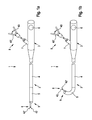
- the endoscope shaft 2 comprises a first shaft section 4 and a second shaft section 5.
- the second shaft section 5 is the distal end section of the endoscope shaft 2
- the first shaft section 4 is the proximal part of the endoscope shaft 2, which occupies the entire remaining length of the endoscope shaft 2 in the example shown and is significantly longer than the second shaft section 5.
- On the handle 3, a symbolically illustrated operating element 6 for controlling a bending of the second shaft portion 5 is arranged.
- the control element 6 may be formed as a hand wheel, lever or crank, but may also be, for example, an operating element for driving a motor.
- the handle 3 a guide tube 7, in which an exemplified, not inventively controllable endoscopic working instrument 8 introduced and can be guided by a extending within the endoscope 2 working channel to the distal end 9 of the endoscope shaft 2 and beyond.
- the working instrument 8 has, for example, at its distal end for gripping or cutting trained tool with two mutually opposing jaw members 42, 42 ', which can be actuated via proximally arranged handles 43, 43'.
- Fig. 1a the endoscope shaft 2 is shown in an extended state while Fig. 1b the endoscope 1 the Fig. 1a in an angled condition.
- the instrument 8 and the first shaft portion 4 are flexible, but not actively controlled.
- the second shaft portion 5 of the endoscope shaft 2 is actively curvable by actuation of the control element 6 and thus controllable.
- the second shaft portion 5 has in its interior a support structure made of articulated shaft segments, which cooperate for bending with at least two opposite, guided within the second shaft portion 5 traction means.
- Each of the traction means is connected to the handle 3 and the operating element 6 by a respective torsion shaft, which runs through the first shaft section 4.
- the endoscope shaft 2 can be separable from the handle 3 via a coupling and can be connected to it again (not shown).
- the endoscope shaft 2 may be reinforced in sections by a surrounding metal mesh.
- the first shank portion 4 and the second shank portion 5 may be surrounded by a flexible sheath, which may for example be a hose made of a plastic material.
- the distal end region of the second shaft section 5 may be rigid and accommodate optical and electronic components, such as an endoscope objective and optionally an electronic image sensor (not shown).
- a flexible endoscopic instrument according to the invention is constructed according to an exemplary embodiment like that in FIG Fig. 1a and 1b illustrated flexible endoscope 1, however, has no optics.
- the flexible endoscopic instrument can comprise the endoscopic working instrument 8 or can also be designed as an endoscopic guide instrument for guiding and controlling a non-controllable endoscopic working instrument 8.
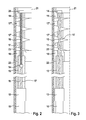
- Fig. 2 is an embodiment of the invention with a trained as a cable Traction means of the second shaft portion 5 of the endoscope shaft 2 (s. Fig. 1 ), which is connected via a cord drive with the torsion shaft 10 arranged in the first shaft section 4, shown in longitudinal section, wherein only the half of the longitudinal section located on one side of the longitudinal axis is shown.
- the torsion shaft 10 can be driven by a motor at its proximal end, in particular by a rotary electric motor arranged in a handle, not shown.
- the torsion shaft 10 is elongated, thin and as rotationally stiff as possible.
- the torsion shaft 10 may be made of nitinol, for example.
- the torsion shaft 10 may for example be designed as a thin, flexible tube. At the distal end of the torsion shaft 10, this is rotatably connected to a proximal connecting piece 12 which is rotatably mounted within the first shaft portion 4; against a longitudinal displacement, in particular in the distal direction, the proximal connector 12 is supported on a guide 13. In the guide 13, a distal connector 14 is mounted longitudinally displaceable. The distal connector 14 may be secured against rotation by the guide 13 and / or the pull wire 16 described below, which may be substantially rotationally rigid, and the support 20 mounted in a rotationally fixed manner in the end segment 19.
- the proximal connector 12 and the distal connector 14 are connected by two substantially mutually parallel twisted wires 15, 15 'held in the proximal connector 12 and the distal connector 14, respectively.
- the twisted wires 15, 15 ' may be provided, for example, in the proximal connector a micro-bolt, around which a wire is wound, the two ends of the twisting wires 15, 15' form.
- the cord drive formed by the connecting pieces 12, 14, the guide 13 and the twisting wires 15, 15 ' is disposed in a distal end portion of the first shaft portion 4. This can be rigid or formed with little flexibility without substantial restriction of the functionality of the endoscope, whereby a simple formation of the cord drive is made possible.
- the guide 13 is formed as a flexible tube.
- the distal connecting piece 14 is connected in a tension-proof manner to a puller wire 16, which is guided in an edge region of the second shaft section.
- the second shaft portion 5 has a support structure, from the in Fig. 2 symbolically three segments 17, 17 ', 17 "as well a proximal end segment 18 and a distal end segment 19 are shown.
- the guide 13 of the cord drive is fixed or mounted in the proximal end segment 18.
- In the distal end segment 19 of the puller wire 16 is held by a holder 20.
- the distal end segment 19 can have further components, for example an endoscope objective and / or outputs of channels extending within the endoscope shaft.
- the puller wire 16 is guided through corresponding openings or bores in the edge region of the segments 18, 17, 17 ', 17 “, 19 Fig. 2 can be seen, the holder 20 of the puller wire 16 is radially offset relative to a longitudinal axis 21 of the second shaft portion 5 and thus also with respect to the pivot axes with which the segments 18, 17, 17 ', 17 “, 19 are pivotally mounted against each other, and are substantially perpendicular to the longitudinal axis 21 and these intersect and preferably alternately perpendicular to each other, so that the differently directed pivot axes allow bending in all directions.
- the torsion 10 by the in Fig. 2 Motor not shown set in rotation the twisted wires 15, 15 'are taken from the proximal connector 12 and compared to the rotatably guided in the endoscope shaft distal connector 14 and thus twisted against each other.
- the twisted wires 15, 15 'can realize, for example, at a length of about 60-80 mm a Switzerlandweg of about 8 mm, which is achieved after about 50 revolutions.
- an untwisted cord length of about 50 to 200 mm is necessary, in particular more than 100 mm. Due to the off-axis arrangement of the holder 20 thereby tilting of the distal end segment 19 and, depending on the design of the articulated connection between the segments 18, 17, 17 ', 17 ", 19, a corresponding tilting of the segments 17, 17', 17th "causes. This results in a curvature of the second shaft portion 5 and thereby a bend of the second shaft section 5 or of the endoscope tip formed by the distal end segment 19.
- a reverse rotation of the torsion shaft leads to a relaxation of the twisting wires 15, 15 '.
- a twisting of the twisting wire on the opposite side may cause the second shank portion 5 to bend in the opposite direction, that of the puller wire 16, the second connecting piece 14 and the twisting wires 15, 15 ', respectively, due to untwisting followed by the proximal-sided coupling described below.
- a thrust force for bending the second shaft portion 5 can be exerted in the opposite direction
- four pairs of counter-acting line drives, each with a torsion shaft 10 may be provided, which are each offset by 90 ° to each other with respect to the longitudinal axis 21 Fig. 2 are also an outer shell 22 which surrounds the first shaft portion, and the outer shell associated with this 23, which surrounds the second shaft portion, indicated.
- Fig. 3 is also shown as a half-sided longitudinal section an embodiment of the invention in which no puller wire for effecting the bending of the second shaft portion 5 is required, but instead of the pull wire, the twisting wires 15, 15 'in the second shaft portion 5 are guided.
- a torsion shaft 10 which is driven by an electric motor at its proximal end.
- the torsion shaft 10 drives a proximal connector 12 in which the twisted wires 15, 15 'are mounted.
- the proximal connection piece 12 is rotatable in a proximal end segment 18 of the second shaft section, but is not longitudinally displaceable, at least in the distal direction.
- the twisting wires 15, 15 'or the cord drive may be guided in a flexible sleeve, and the proximal connecting piece 12 is arranged to be rotatable relative to this sleeve Fig. 3 As shown, the cord drive may be longer than the second shaft portion 5 to maximize the achievable angulation.
- twisting of the twisting wires 15, 15 'in an extended position of the second shaft portion corresponding output position due to rotation of the torsion shaft 10 is exerted on the distal connector 14 an axial pull in the proximal direction. Due to the off-axis arrangement of the distal connecting piece 14, this causes a bending of the second shaft portion.
- a reverse rotation of the torsion shaft leads to a relaxation of the twisting wires 15, 15 ', so that about a arranged on the radially opposite side, similarly constructed mechanism, a bending in the opposite direction can be effected.
- Fig. 3 shows twisting of the twisting wires 15, 15 'in an extended position of the second shaft portion corresponding output position due to rotation of the torsion shaft 10 is exerted on the distal connector 14 an axial pull in the proximal direction. Due to the off-axis arrangement of the distal connecting piece 14, this causes a bending of the second shaft portion.
- a reverse rotation of the torsion shaft leads to a relaxation of the twist
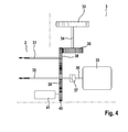
- an endoscope shaft 2 can have a first and a second torsion shaft 30, 31, which can be driven both via a hand wheel 32 and via a motor 33.
- the handwheel 32 is connected via a shaft 34 with a gear 35; it can be an in Fig. 4 not shown reduction can be provided, causing for example one revolution of the handwheel 5 to 10 revolutions of the torsion waves.
- the motor 33 drives a motor shaft 36 having a clutch 37.
- the coupling may be formed, for example, as a sliding clutch, magnetic coupling, PTO or in another manner known per se.
- Handwheel 32 and motor 33 and the shafts 34 and 36, the gear 35 and the clutch 37 are associated with a handle 3, which can be attached to the endoscope shaft 2.
- the rotary encoder 41 registers the rotation of the gear 40, from which a rotational position of the torsion shafts 30, 31 can be determined. In a storage device, not shown, this rotational position is stored and transmitted when coupling the shaft 2 to the handle 3 to a likewise not shown control device of the motor 33. As a result, it is possible at any time to achieve a control of the motor 33 corresponding to the actual position of the drives.
Landscapes
- Health & Medical Sciences (AREA)
- Life Sciences & Earth Sciences (AREA)
- Surgery (AREA)
- Nuclear Medicine, Radiotherapy & Molecular Imaging (AREA)
- Molecular Biology (AREA)
- Veterinary Medicine (AREA)
- Public Health (AREA)
- General Health & Medical Sciences (AREA)
- Animal Behavior & Ethology (AREA)
- Engineering & Computer Science (AREA)
- Biomedical Technology (AREA)
- Heart & Thoracic Surgery (AREA)
- Medical Informatics (AREA)
- Physics & Mathematics (AREA)
- Biophysics (AREA)
- Radiology & Medical Imaging (AREA)
- Pathology (AREA)
- Optics & Photonics (AREA)
- Instruments For Viewing The Inside Of Hollow Bodies (AREA)
Description
- Die vorliegende Erfindung betrifft einen Schaft für ein flexibles Endoskop oder für ein flexibles endoskopisches Instrument nach dem Oberbegriff von Anspruch 1 sowie ein flexibles Endoskop und ein flexibles endoskopisches Instrument mit einem derartigen Schaft.
- Flexible Endoskope werden für eine Vielzahl von Anwendungen in Medizin und Technik eingesetzt. Derartige flexible Endoskope umfassen einen flexiblen lang erstreckten Schaft, der zur Einführung in einen Hohlraum, etwa einen körperinneren Hohlraum oder einen Hohlraum eines technischen Objekts, geeignet ist. In der Regel ist an der Spitze des Endoskopschafts ein Endoskopobjektiv zur Erzeugung eines Bildes einer Szene in dem beobachteten Hohlraum angeordnet. Zur Aufnahme und Weiterleitung des endoskopischen Bildes vom distalen (d.h. beobachterfernen) zum proximalen (d.h. beobachternahen) Endbereich des Endoskops kann beispielsweise ein innerhalb des Schafts verlaufendes geordnetes Bündel von Lichtleitfasern vorgesehen sein oder auch ein elektronischer Bildaufnehmer, etwa ein CCD-Chip, der im Bereich des distalen Endes des Schafts angeordnet ist, und dessen Signale über innerhalb des Schafts verlaufende elektrische Leitungen zum proximalen Endbereich übertragen werden. Da in der Regel in dem beobachteten Hohlraum nicht ausreichend Licht vorhanden ist, kann ferner innerhalb des Schafts ein Lichtleitsystem angeordnet sein, um Licht an das distale Ende des Endoskops zu transportieren, wo es zur Beleuchtung des Hohlraums genutzt wird. Weiterhin kann der Endoskopschaft einen oder mehrere Arbeitskanäle zur Durchführung von endoskopischen Arbeitsinstrumenten vom proximalen zum distalen Endbereich des Schafts enthalten, mit deren Hilfe innerhalb des Hohlraums Manipulationen ausgeführt werden können.
- Es sind auch endoskopische Instrumente bekannt, die einen flexiblen lang erstreckten Schaft umfassen, der ebenfalls zur Einführung in einen Hohlraum, etwa einen körperinneren Hohlraum oder einen Hohlraum eines technischen Objekts, geeignet ist. Ein derartiges flexibles endoskopisches Instrument kann zur Durchführung von Manipulationen in dem Hohlraum verwendbar sein und hierfür beispielsweise als Fassinstrument zum Greifen und Manipulieren von Gewebe oder Gegenständen in dem körperinneren Hohlraum bzw. in dem Hohlraum eines technischen Objekts ausgebildet sein. Hierfür ist am distalen Ende des flexiblen Schafts ein Werkzeug angeordnet, das über ein innerhalb des Schafts verlaufendes Übertragungsmittel vom proximalen Ende des Schafts her bedient werden kann. Ein solches flexibles endoskopisches Instrument weist in der Regel keine eigene Optik zur Aufnahme eines endoskopischen Bildes auf, kann aber insbesondere gemeinsam mit einem flexiblen Endoskop verwendbar sein.
- Häufig ist es wünschenswert, das distale Ende des Schafts, d.h. die Spitze des Endoskops bzw. des endoskopischen Instruments, abwinkeln zu können, um die Einführung des Endoskops bzw. des endoskopischen Instruments durch einen nicht geradlinig verlaufenden Kanal zu erleichtern, um die Spitze innerhalb eines Hohlraums in einer seitlichen Richtung bewegen zu können und um die Blickrichtung einer in der Endoskopspitze angeordneten Optik bzw. die Arbeitsrichtung eines an der Spitze des endoskopischen Instruments angeordneten Werkzeugs verändern zu können. Hierfür weist der Schaft einen steuerbaren Abschnitt, insbesondere einen steuerbaren Endabschnitt, auf, der aktiv um einen gewünschten Betrag in eine gewünschte Richtung abgewinkelt werden und hierfür vom proximalen Ende des Endoskops bzw. des endoskopischen Instruments her gesteuert werden kann. Der Schaft für ein flexibles endoskopisches Instrument muss nicht selbst ein Werkzeug und ein Übertragungsmittel aufweisen, sondern kann beispielsweise einen Arbeitskanal umfassen, in den ein flexibles endoskopisches Arbeitsinstrument, das nicht aktiv abwinkelbar ist und das ein solches Werkzeug aufweist, bis zum distalen Ende des Schafts und ggf. darüber hinaus eingeführt werden kann, so dass das flexible Arbeitsinstrument mit Hilfe des Schafts abgewinkelt werden kann.
- Um eine steuerbare Abwinkelung eines Abschnitts eines Schafts eines flexiblen Endoskops zu ermöglichen, ist es bekannt, diesen mit einer Grundstruktur aus einzelnen gegeneinander schwenkbaren Segmenten auszubilden, die durch im Endoskopschaft geführte Seilzüge bzw. Bowdenzüge betätigt werden können. Zur Betätigung sind insbesondere am Endoskophandgriff angeordnete Handräder vorgesehen. Gemäß
US 2005/0131279 A1 ist jedes Segment eines steuerbaren Abschnitts des Endoskopschafts relativ zum nächsten bzw. vorhergehenden Segment schwenkbar gelagert. Zum Abwinkeln des betreffenden Schaftabschnitts bzw. der Endoskopspitze sind vier Seilzüge vorgesehen, die von einer proximal angeordneten Steuerungseinrichtung bis zur Endoskopspitze geführt sind. Die Seilzüge verlaufen im Randbereich der Segmente und sind bezüglich einer Längsachse jeweils um 90° zueinander versetzt, so dass eine Steuerung der Endoskopspitze in eine gewünschte Richtung durch Aufrollen der entsprechenden Seile in der Steuerungseinrichtung bewirkt werden kann. - Die Seile derartiger Seilzüge neigen jedoch dazu, sich nach mehrfachem Gebrauch zu längen, was die Steuerbarkeit der Endoskopspitze beeinträchtigt oder eine regelmäßige Nachspannung der Seilzüge erforderlich macht. Nachstellvorrichtungen zur Einstellung der Spannung der Seilzüge sind beispielsweise aus
DE 29 14 748 C2 undUS 4,203,430 bekannt; derartige Nachstellvorrichtungen sind jedoch mit einem erhöhten konstruktiven und Bedienungsaufwand verbunden. Die erforderliche dauerhafte Spannung der Seilzüge kann ferner zu einer Verkürzung des Schafts führen, was die Steuerbarkeit der Endoskopspitze sowie überhaupt die Eigenschaften des Endoskopschafts, etwa die Flexibilität oder die Oberflächenbeschaffenheit, nachteilig beeinflussen kann. Die erzielbare Abwinkelung hängt dabei außerdem von der Krümmung des gesamten Schaftabschnitts ab, durch den die Seilzüge geführt sind, so dass kein eindeutiger Zusammenhang zwischen der Stellung eines Handrads, mit dem ein Seilzug aufgerollt werden kann, und dem erzielten Ablenkwinkel der Endoskopspitze besteht. Krümmungen des Endoskopschafts verursachen ferner eine erhöhte Reibung der Seilzüge, was die Bedienbarkeit der Abwinkelung ebenfalls erschwert. Schließlich können die Seilzüge, insbesondere bei längeren Schäften, aufgrund der Reibung und eines entsprechenden Verschleißes reißen. - In
JP 07134253 A - Es ist die Aufgabe der vorliegenden Erfindung, einen Schaft für ein flexibles Endoskop oder ein flexibles endoskopisches Instrument sowie ein flexibles Endoskop und ein flexibles endoskopisches Instrument anzugeben, wobei die oben genannten Nachteile vermieden werden und wobei der Schaft insbesondere einfach aufgebaut, dauerhaft und robust ist und mit einem kleinen Durchmesser ausgebildet werden kann.
- Diese Aufgabe wird durch einen Schaft gemäß Anspruch 1 sowie durch ein flexibles Endoskop gemäß Anspruch 9 und ein flexibles endoskopisches Instrument gemäß Anspruch 10 gelöst. Vorteilhafte Weiterbildungen der Erfindung ergeben sich aus den Unteransprüchen.
- Ein erfindungsgemäßer Schaft für ein flexibles Endoskop oder für ein flexibles endoskopisches Instrument ist lang erstreckt und zur Einführung in einen Hohlraum, beispielsweise einen körperinneren Hohlraum oder einen Hohlraum eines technischen Objekts, ausgebildet. Das flexible Endoskop kann insbesondere einen an einem proximalen Ende des Schafts angeordneten Handgriff umfassen, der Bedienelemente und/oder Anschlüsse für weitere Geräte, etwa eine Saug- und Spüleinrichtung, eine Lichtquelle oder eine Kameraeinheit, aufweisen kann. Der Handgriff kann auch eine Kamera enthalten. Das flexible endoskopische Instrument kann insbesondere einen an einem proximalen Ende des Schafts angeordneten Handgriff mit einem Betätigungselement für ein am distalen Ende des Schafts angeordnetes Werkzeug aufweisen. Das flexible Endoskop bzw. das flexible endoskopische Instrument ist insbesondere zur Verwendung bei medizinischen, insbesondere chirurgischen Eingriffen oder für technische Anwendungen ausgebildet.
- Der Schaft umfasst einen ersten Schaftabschnitt sowie einen distalseitig des ersten Schaftabschnitts angeordneten zweiten Schaftabschnitt, der insbesondere an einen distalen Endbereich des ersten Schaftabschnitts anschließen kann. Der Schaft kann weitere Schaftabschnitte umfassen. Der zweite Schaftabschnitt kann beispielsweise als abwinkelbare Endoskopspitze ausgebildet sein. Der zweite Schaftabschnitt ist relativ zu dem distalen Endbereich des ersten Schaftabschnitts abwinkelbar. Insbesondere ist der zweite Schaftabschnitt aktiv krümmbar ausgebildet, während der erste Schaftabschnitt zumindest teilweise flexibel ausgebildet, jedoch nicht aktiv krümmbar ist.
- Innerhalb des zweiten Schaftabschnitts ist mindestens ein in Längsrichtung des zweiten Schaftabschnitts wirkendes Zugmittel angeordnet. Der Begriff "Zugmittel" umfasst hier beispielsweise einen Draht oder ein Zugseil, das eine Zugkraft ausübt, kann aber auch als Schubmittel ausgebildet sein, beispielsweise als steifer Draht oder als in einer Hülle geführter Draht, etwa als Bowdenzug, der zur Übertragung sowohl von Zug- als auch Schubkräften in Längsrichtung des zweiten Schaftabschnitts geeignet ist. Der zweite Schaftabschnitt ist relativ zu einem distalen Endbereich des ersten Schaftabschnitts durch eine Längsverstellung des Zugmittels abwinkelbar. Insbesondere wirkt das Zugmittel derart mit einer Stützstruktur des zweiten Schaftabschnitts zusammen, dass eine Längenänderung oder eine Längsverschiebung des Zugmittels eine Abwinkelung des zweiten Schaftabschnitts bewirkt, insbesondere eine Krümmung des zweiten Schaftabschnitts. Hierfür kann das Zugmittel von einem proximalen zu einem distalen Endbereich des zweiten Schaftabschnitts geführt sein und zumindest im distalen Endbereich mit der Stützstruktur verbunden sein. Die Stützstruktur kann beispielsweise aus einer Abfolge miteinander gelenkig verbundener Segmente bestehen, wobei das Zugmittel gegenüber den Gelenken seitlich versetzt an mindestens einem Endsegment der Stützstruktur angreift.
- Erfindungsgemäß ist mindestens ein Schnurantrieb zur Längsverstellung des mindestens einen Zugmittels angeordnet. Der Schnurantrieb kann hierfür etwa ein Teil des Zugmittels sein oder an diesem angreifen. Ein Schnurantrieb, der auch als Verdrillungsantrieb bezeichnet wird, umfasst eine Mehrzahl an Schnüren oder Drähten, die miteinander verdrillbar angeordnet sind, oder auch ein einzelnes, aus mehreren Schnüren geflochtenes Seil, das um sich selbst verdrillbar angeordnet ist. Auch die miteinander zu verdrillenden Schnüre oder Drähte können selbst jeweils aus mehreren Schnüren bzw. Drähten geflochten sein, wodurch eine erhöhte Zugfestigkeit erreichbar ist. Wenn im Folgenden von "Verdrillungsschnüren" die Rede ist, sind damit auch Verdrillungsdrähte oder ein aus mehreren Schnüren geflochtenes Seil gemeint. In Abhängigkeit von dem Grad der Verdrillung bzw. der Anzahl von Umdrehungen zur Verdrillung variiert die wirksame Länge des Schnurantriebs. Die Veränderung der Länge ist auch abhängig vom Durchmesser und der Anzahl der miteinander zu verdrillenden Schnüre oder Drähte. Der Schnurantrieb ist beispielsweise durch eine Welle antreibbar, die in Längsrichtung des zweiten bzw. des Endbereichs des ersten Schaftabschnitts verlaufen kann, oder auch durch eine innerhalb des Schafts angeordneten Motor.
- Dadurch, dass ein Schnurantrieb zur Längsverstellung des Zugmittels vorgesehen ist, kann eine Abwinkelung des zweiten Schaftabschnitts des Schafts mit ausreichender Kraft auch bei einem kleinen Schaftdurchmesser realisiert werden. Ferner ist ein Schnurantrieb einfach aufgebaut, robust und kostengünstig herstellbar.
- Vorzugsweise sind zur Steuerung der Längsverstellung des Zugmittels und damit der Abwinkelung des zweiten Schaftabschnitts Betätigungsmittel vorgesehen, die proximalseitig des ersten Schaftabschnitts angeordnet sind und beispielsweise als ein an einem Handgriff angeordnetes Handrad oder als in einem Handgriff angeordneter Motor ausgebildet sein können. Weiter ist zur Steuerung der Abwinkelung des zweiten Schaftabschnitts relativ zum distalen Endbereich des ersten Schaftabschnitts mindestens eine Torsionswelle innerhalb des ersten Schaftabschnitts angeordnet, durch die eine von den Betätigungsmitteln erzeugte Betätigungsbewegung zum zweiten Schaftabschnitt bzw. zu einem Endbereich des ersten Schaftabschnitts übertragbar ist, um den mindestens einen Schnurantrieb anzutreiben und dadurch eine Längsverstellung des mindestens einen Zugmittels zu bewirken. Die Torsionswelle ist insbesondere lang erstreckt, durchgehend vom proximalen zum distalen Endbereich des ersten Schaftabschnitts und zumindest abschnittsweise flexibel ausgebildet. Die Torsionswelle kann innerhalb des ersten Schaftabschnitts in einem Randbereich des Querschnitts geführt sein, so dass eine ausreichende Querschnittsfläche für die Durchführung weiterer Kanäle bzw. elektrischer und Lichtleitungen verbleibt. Durch die Rotation der mit dem Schnurantrieb gekoppelten Torsionswelle ist somit die Längsverstellung des Zugmittels zur Steuerung der Abwinkelung des zweiten Schaftabschnitts steuerbar.
- Dadurch, dass die Längsverstellung des Zugmittels durch proximal angeordnete Betätigungsmittel steuerbar ist, die eine Rotationsbewegung erzeugen, die über mindestens eine innerhalb des ersten Schaftabschnitts verlaufende Torsionswelle zum Schnurantrieb übertragen wird, kann durch leicht bedienbare Betätigungsmittel eine Betätigungsbewegung zur Steuerung der Abwinkelung des zweiten Schaftabschnitts erzeugt werden, die auf einfache Weise durch einen mit einem geringen Durchmesser ausgebildeten Schaft übertragen werden kann. Insbesondere wird die Betätigungsbewegung direkter zum zweiten Schaftabschnitt übertragen, als dies mit Seil- bzw. Bowdenzügen möglich wäre. Dabei wird keine Zug- oder Druckkraft auf den ersten Schaftabschnitt ausgeübt, der in der Regel den überwiegenden Teil der Gesamtlänge des Schafts ausmacht, so dass eine Stauchung des Schafts vermieden wird. Ferner ist keine Nachspannung von Seilzügen, die sich im Laufe der Zeit verlängern könnten, erforderlich. Weiterhin ist die bis zum zweiten Schaftabschnitt übertragene Betätigungsbewegung weitgehend unabhängig von der Länge und der Krümmung des ersten Schaftabschnitts, so dass die Steuerbarkeit der Abwinkelung des zweiten Schaftabschnitts verbessert ist. Auf diese Weise wird insbesondere ein einfach aufgebauter flexibler Schaft für ein flexibles Endoskop bzw. für ein flexibles endoskopisches Instrument geschaffen, bei dem ein abwinkelbarer distaler Schaftabschnitt unabhängig von einer Krümmung eines proximalen Schaftabschnitts mit proximal angeordneten Betätigungsmitteln steuerbar ist, und der auch mit einem Schaftdurchmesser von beispielsweise weniger als 6 mm, insbesondere 4 mm oder weniger ausführbar ist.
- Gemäß einer bevorzugten Ausführungsform der Erfindung ist die Torsionswelle mit dem Zugmittel zur Steuerung der Längsverstellung des Zugmittels über einen Schnurantrieb verbunden. Ein solcher Schnurantrieb umfasst insbesondere zwei in einer Ausgangsposition umeinander verdrillte, im Wesentlichen in Längsrichtung verlaufende Verdrillungsschnüre, die jeweils in einem proximalen und einem distalen Verbindungsstück gehalten sind. Das proximale Verbindungsstück ist drehfest mit dem distalen Ende der Torsionswelle verbunden und drehbar, aber in Längsrichtung abgestützt im Endoskopschaft gelagert, während das distale Verbindungsstück drehfest, jedoch längsverschiebbar innerhalb des Endoskopschafts geführt ist und mit einem proximalen Ende des innerhalb des zweiten Schaftabschnitts geführten Zugmittels verbunden ist. Eine Rotation der Torsionswelle in einer ersten Richtung führt zu einer weiteren Verdrillung der Verdrillungsschnüre umeinander und dadurch zu einer Verkürzung, wodurch das distale Verbindungsstück sich auf das proximale Verbindungsstück zu bewegt und somit einen Zug auf das Zugmittel in seinem proximalen Bereich in proximaler Richtung ausübt. Wenn die Ausgangsposition der Verdrillungsschnüre einer gestreckten, d.h. nicht abgewinkelten Stellung des zweiten Schaftabschnitts entspricht, wird hierdurch eine Abwinkelung des zweiten Schaftabschnitts bewirkt. Eine Rotation der Torsionswelle in entgegengesetzter Richtung führt zu einer Entdrillung der Verdrillungsschnüre, so dass durch eine elastische Rückstellkraft oder durch eine auf einer gegenüberliegenden Seite des Schafts angreifende, entgegenwirkende Zugkraft eine Verringerung der Abwinkelung bewirkt werden kann. Der Schnurantrieb kann in einem proximalen Endbereich des zweiten Schaftabschnitts, in einem distalen Endbereich des ersten Schaftabschnitts, übergreifend in beiden Schaftabschnitten oder in einem Übergangsabschnitt zwischen dem ersten und dem zweiten Schaftabschnitt angeordnet sein. Der Übergangsabschnitt muss nicht unbedingt flexibel ausgebildet sein. Dadurch, dass eine Längsverschiebung und damit eine Längsverstellung des Zugmittels über einen Schnurantrieb bewirkt wird, ist auf besonders einfache Weise eine Umsetzung der Rotationsbewegung der Torsionswelle in eine Längsverstellung des Zugmittels zur Steuerung der Abwinkelung des zweiten Schaftabschnitts möglich.
- Gemäß einer weiteren bevorzugten Ausführungsform der Erfindung ist das Zugmittel zumindest abschnittsweise selbst als der Schnurantrieb bzw. als Verdrillungsschnüre des Schnurantriebs ausgebildet. Gemäß dieser Ausführungsform ist die Torsionswelle drehfest mit einem proximalen Verbindungsstück verbunden, in dem mindestens zwei Verdrillungsschnüre befestigt sind, die durch den zweiten Schaftabschnitt bis in dessen distalen Endbereich geführt sind und dort in einem mit einer Stützstruktur des zweiten Schaftabschnitts, beispielsweise mit einem Endsegment, verbundenen distalen Verbindungsstück gehalten sind. Das proximale Verbindungsstück ist mit der Torsionswelle drehbar gelagert und durch diese antreibbar, während das distale Verbindungsstück drehfest mit dem Schaft, insbesondere mit dem zweiten Schaftabschnitt, verbunden ist. Beide Verbindungsstücke sind gegen eine Längsverschiebung im jeweiligen Bereich des Endoskopschafts abgestützt. Durch eine Rotation der Torsionswelle rotiert daher das proximale Verbindungsstück relativ zum distalen Verbindungsstück, wodurch die Verdrillungsschnüre gegeneinander verdrillt werden und die Länge des Zugmittels, das zumindest abschnittsweise durch die Verdrillungsschnüre gebildet wird, verändert wird. Ausgehend von einer Ausgangsposition, in der die Verdrillungsschnüre in einem gewissen Maße miteinander verdrillt sind, wird durch eine weitere Verdrillung aufgrund einer entsprechenden Rotation der Torsionswelle eine Verkürzung des Zugmittels bewirkt, während eine entgegengesetzte Rotation eine Verlängerung ermöglicht. Auf diese Weise wird eine Verkürzung bzw. Verlängerung und damit eine Längsverstellung des Zugmittels bewirkt, wobei eine Längsführung eines der Verbindungsstücke sowie ein separates Zugmittel nicht notwendig sind. Hierdurch wird auf eine besonders einfache Weise eine Steuerung der Abwinkelung des zweiten Schaftabschnitts durch eine Rotation der Torsionswelle ermöglicht.
- Vorzugsweise weist der zweite Schaftabschnitt eine Mehrzahl von Zugmitteln auf, die einander paarweise gegenüber liegend angeordnet sind. Bei einer Abwinkelung des zweiten Schaftabschnitts wirken somit jeweils zwei Zugmittel einander entgegen, wobei die jeweiligen Längsverstellungen der Zugmittel einander entgegenwirkend sind. Hierdurch kann eine Abwinkelung in unterschiedliche Richtungen mit einer besonders hohen Genauigkeit und einer stets ausreichenden Kraft erzielt werden, da in jeder Abwinkelungsrichtung eines der Zugmittel verkürzt bzw. das distale Ende eines der Zugmittel in proximale Richtung gezogen wird.
- Insbesondere können zwei in Bezug auf eine Längsachse des zweiten Schaftabschnitts um 90° zueinander versetzte Paare von Zugmitteln vorgesehen sein, um eine Abwinkelung des zweiten Schaftabschnitts in aufeinander senkrecht stehenden Richtungen zu ermöglichen. Hierdurch ist auf eine besonders einfache Weise eine Abwinkelung, von einem Benutzer gesehen, sowohl nach links oder rechts als auch nach oben oder unten sowie durch eine gleichzeitige Betätigung der Paare von Zugmitteln eine Abwinkelung in jede dazwischen liegende Richtung möglich.
- Alternativ können beispielsweise drei bezüglich der Längsachse um jeweils etwa 120° versetzte Zugmittel vorgesehen sein. Auch hierdurch ist eine Abwinkelung in alle Richtungen erreichbar.
- In vorteilhafter Weise ist eine Mehrzahl von Torsionswellen vorgesehen, die mit der Mehrzahl von Zugmitteln zur Steuerung einer Abwinkelung des zweiten Schaftabschnitts zusammenwirken. Insbesondere kann jede Torsionswelle mit jeweils einem Zugmittel bzw. jeweils einem Schnurantrieb verbunden sein. Hierdurch wird auf einfache Weise eine Abwinkelung des zweiten Schaftabschnitts in unterschiedliche Richtungen mit einer besonders hohen Genauigkeit ermöglicht.
- Gemäß einer bevorzugten Ausführungsform der Erfindung sind die mehreren Torsionswellen über ein Zahnradgetriebe derart miteinander verbunden, dass einander gegenüber liegende Zugmittel jeweils gegensinnig bewegbar sind. Insbesondere kann das Zahnradgetriebe an einem proximalen Ende der Torsionswelle angeordnet sein, wobei jeweils zwei einander gegenüber liegenden Schnurantrieben zugeordnete Torsionswellen miteinander gekoppelt sind. Durch das Zahnradgetriebe ist eine derartige Kopplung möglich, dass eine Verlängerung eines Zugmittels zu einer gleichzeitigen Verkürzung eines diesem gegenüber liegenden und diesem entgegenwirkenden Zugmittels führt bzw. eine Verschiebung eines Zugmittels in proximaler Richtung zu einer Verschiebung eines diesem gegenüber liegenden und diesem entgegenwirkenden Zugmittels in distaler Richtung führt. Hierfür kann beispielsweise jede der beiden einander entgegenwirkenden Torsionswellen an ihrem proximalen Ende drehfest ein Zahnrad tragen, wobei die beiden Zahnräder miteinander kämmen, so dass die Torsionswellen stets gegensinnig rotieren und gegenläufige Längenänderungen gleichsinnig verdrillter Schnurantriebe bewirken. Sind die beiden entsprechenden Schnurantriebe in der Ausgangsposition in unterschiedliche Richtungen verdrillt, so kann eine ungerade Anzahl von Zahnrädern zwischen die beiden mit den Torsionswellen verbundenen Zahnräder zwischengeschaltet sein, so dass die beiden Torsionswellen gleichsinnig rotieren und gegenläufige Längenänderungen der gegensinnig verdrillten Schnurantriebe bewirken. Hierdurch wird die Bedienbarkeit und Steuerbarkeit der Abwinkelung des zweiten Schaftabschnitts weiter verbessert.
- Da ein Schnurantrieb im Allgemeinen einen nichtlinearen Zusammenhang zwischen Verdrillung und Längenänderung aufweist, ist es besonders vorteilhaft, wenn die Ausgangsposition beider einander entgegenwirkender Schnurantriebe, die einer gestreckten Stellung des zweiten Schaftabschnitts entsprechen kann, in einem Verdrillungsbereich gewählt ist, in dem zumindest abschnittsweise ein linearer Zusammenhang zwischen dem Winkel bzw. der Zahl der Umdrehungen einer weiteren Verdrillung oder einer Entdrillung einerseits und der dadurch bewirkten Längenänderung andererseits besteht. Hierdurch ist die Abwinkelung des zweiten Schaftabschnitts genauer steuerbar und insbesondere ein gewünschter Abwinkelungswinkel genauer erreichbar. Ferner kann hierdurch auf besonders einfache Weise zumindest in einem eingeschränkten Winkelbereich ein spannungsarmes Entgegenwirken der einander gegenüberliegenden Schnurantriebe und der damit gekoppelten Torsionswellen zur Abwinkelung des zweiten Schaftabschnitts in unterschiedliche Richtungen erreicht werden. Um einen größeren Winkelbereich der Abwinkelung zu ermöglichen, können die Zugmittel bzw. die Schnurantriebe elastisch dehnbar ausgebildet sein und unter einer Vorspannung stehen.
- Vorzugsweise umfasst der Schnurantrieb mindestens zwei Verdrillungsschnüre aus einem polymeren Material. Ein solches polymeres Material kann aus Polyethylen (PE) - Fasern bestehen, wie diese beispielsweise unter der Bezeichnung "Dyneema®" von der Fa. DSM erhältlich sind. Eine solche Schnur ist ausreichend belastbar und dauerflexibel und ermöglicht somit dauerhaft eine exakte Bedienung der Abwinkelung des zweiten Schaftes. Eine aus mehreren Schnüren geflochtene Verdrillungsschnur kann beispielsweise einen Durchmesser von etwa 0,15 mm aufweisen; zwei Verdrillungsschnüre können somit wie in einem Bowdenzug in einer Hülse mit einem Innendurchmesser von ca. 0,30 mm geführt werden.
- Ein erfindungsgemäßes Endoskop umfasst einen oben beschriebenen Schaft, der als Endoskopschaft ausgebildet ist. Durch den Schaft können insbesondere Lichtleiter, Bildleiter, Saug- bzw. Spülkanäle und/oder einen oder mehrere Arbeitskanäle für endoskopische Arbeitsinstrumente verlaufen.
- Ein erfindungsgemäßes endoskopisches Instrument umfasst einen langerstreckten Schaft, der wie oben beschrieben ausgebildet ist. Ferner kann ein am distalen Ende des Schafts des endoskopischen Instruments ein Werkzeug angeordnet sein, das über ein innerhalb des Schafts verlaufendes Übertragungsmittel, etwa ein Zugelement, von proximalen Ende des Schafts her, etwa mit Hilfe von proximal angeordneten Griffen, bedient werden kann. Der Schaft des endoskopischen Instruments kann beispielsweise Saug- bzw. Spülkanäle sowie einen Arbeitskanal umfassen, durch den ein nicht aktiv steuerbares endoskopisches Arbeitsinstrument einführbar ist.
- In bevorzugter Weise ist das flexible Endoskop bzw. das flexible endoskopische Instrument derart ausgebildet, dass die mindestens eine Torsionswelle über mindestens ein in einem proximalen Bereich des Endoskops bzw. des endoskopischen Instrument, insbesondere an einem Handgriff, angeordnetes Bedienelement, das etwa als Handrad, Hebel oder Kurbel ausgebildet sein kann, und/oder einen Motor, der beispielsweise in dem Handgriff angeordnet sein kann, betätigt werden kann. Sowohl durch das Bedienelement als auch durch den Motor kann die Torsionswelle in einer für eine genaue Steuerung der Abwinkelung ausreichenden Weise in Rotation versetzt werden. Der Motor kann aber auch beispielsweise in einer vom Endoskop bzw. endoskopischen Instrument sowie ggf. vom Handgriff separaten Motoreinheit angeordnet sein, wobei die Rotationsbewegung über eine flexible Welle zum Endoskopschaft übertragbar sein kann. Die Betätigung über einen Motor, der von einer Steuerungseinrichtung angesteuert werden kann, ist insbesondere auch dann vorteilhaft, wenn die Zugmittel nicht paarweise einander gegenüberliegend, sondern beispielsweise um 120° gegeneinander versetzt angeordnet sind.
- Gemäß einer weiteren bevorzugten Ausführungsform der Erfindung umfasst das flexible Endoskop bzw. das flexible endoskopische Instrument eine Handhabe, insbesondere einen Handgriff, wobei der Schaft über eine Kupplung mit der Handhabe lösbar verbindbar ist. Ein endoskopisches System kann somit eine Mehrzahl von Schäften unterschiedlicher Maße, insbesondere unterschiedlicher Durchmesser und Längen, sowie ggf. unterschiedlichen Aufbaus umfassen, die mit einer Handhabe, die beispielsweise den Antrieb für die Abwinkelung und eine Kamera umfassen kann, verbindbar sind. Dadurch, dass beim Ankoppeln des Schafts an die Handhabe keine in Längsrichtung des Schafts verlaufenden Seilzüge mit der Handhabe verbunden werden müssen, ist es nicht notwendig, diese nach dem Ankoppeln neu zu justieren bzw. zu spannen. Durch die Übertragung der Betätigungsbewegung des Schnurantriebs über eine Torsionswelle wird demgegenüber eine einfachere Verbindung ermöglicht, die lediglich drehfest ausgestaltet sein muss und in Längsrichtung einfach trennbar sein kann. Der Antrieb und eine Steuerungseinrichtung sind in der Handhabe angeordnet. Hierdurch wird ein Endoskop bzw. ein endoskopisches Instrument und/oder ein endoskopisches System geschaffen, das besonders vielseitig einsetzbar ist, jedoch aufgrund der mit einer Mehrzahl von Schäften verwendbaren Handhabe relativ kostengünstig ist und beim Wechseln der Schäfte einen geringen Bedienungsaufwand erfordert.
- In besonders bevorzugter Weise umfasst die Handhabe einen motorischen Antrieb der mindestens einen Torsionswelle bzw. des Schnurantriebs. Beim Abkoppeln des Schafts von der Handhabe wird eine rotatorische Position der mindestens einen Torsionswelle gespeichert, und eine Torsionswellenkupplung der Handhabe ist zum Ankoppeln des Schafts derart ansteuerbar, dass diese bei einem Ankoppeln eine der gespeicherten Rotationsstellung der Torsionswelle entsprechende rotatorische Position einnimmt. Hierdurch wird ein besonders einfaches Ankoppeln des Schafts an die Handhabe ermöglicht. Ferner ermöglicht die Speicherung der Rotationsstellung der Torsionswelle eine besonders genaue Steuerung der Abwinkelung des zweiten Schaftabschnitts auch in dem Fall, dass eine nicht-lineare Beziehung zwischen der Rotationsstellung der Torsionswelle und der Abwinkelung besteht. Die nicht-lineare Beziehung kann in diesem Fall in einer Steuerungseinrichtung gespeichert sein, und aufgrund der Rotationsstellung der Torsionswelle kann eine jeweils aktuelle Rotationsstellung eines Schnurantriebs ermittelt und damit unter Berücksichtigung der nicht-linearen Beziehung die Abwinkelung genau gesteuert werden. Hierdurch kann von der Steuerungseinrichtung auch die jeweils aktuelle Abwinkelungsstellung des zweiten Schaftabschnitts ermittelt werden, so dass etwa bei einer virtuellen Darstellung des Endoskops bzw. des endoskopischen Instruments und des beobachteten Hohlraums die räumliche Position der Endoskopspitze richtig dargestellt werden kann.
- Die rotatorische Position der mindestens einen Torsionswelle, die diese beim Trennen von der entsprechenden Motorwelle einnimmt, ist in vorteilhafter Weise in einem dem Schaft zugeordneten Speicher speicherbar. Hierdurch kann erreicht werden, dass beim Verbinden des Schafts mit einer Handhabe die Kupplung der Motorwelle in die richtige Position gedreht werden kann und die Steuerungseinrichtung die notwendigen Informationen für eine genaue Steuerung der Abwinkelung hat, auch in dem Fall, dass der Schaft mit einer anderen Handhabe verbunden wird.
- Zur Ermittlung der rotatorischen Position der Torsionswelle beim Trennen von der Handhabe kann ein Sensor, etwa ein Potentiometer oder ein anderer Drehgeber, insbesondere ein Absolutwertgeber, etwa ein optischer Multiturn-Drehgeber, vorgesehen sein, der insbesondere in einem proximalen Endbereich des Schafts angeordnet ist. Durch den Sensor werden die Umdrehungen und der zurückgelegte Winkel der Torsionswelle gemessen; der Sensor kann bei einer Trennung vom Antrieb in der entsprechenden Drehposition verharren, so dass ein Auslesen jederzeit möglich ist. Auf diese Weise können die beim Betrieb des Endoskops bzw. des endoskopischen Instruments zur Abwinkelung des zweiten Schaftabschnitts durchgeführten Umdrehungen gezählt und die rotatorische Position der Torsionswelle ermittelt werden.
- Bei der Verwendung eines erfindungsgemäßen Endoskops bzw. eines erfindungsgemäßen endoskopischen Instruments wird somit zum Steuern eines abwinkelbaren Schaftabschnitts, insbesondere einer abwinkelbaren Spitze des Endoskops oder zum Steuern der Arbeitsrichtung eines an der Spitze des endoskopischen Instruments angeordneten Werkzeugs, mit Hilfe eines Bedienelements oder durch einen Motor insbesondere eine in einem ersten, proximalseitig angeordneten Schaftabschnitt verlaufende Torsionswelle gedreht und hierdurch ein in einem zweiten Abschnitt des Schafts verlaufendes Zugmittel in seiner Längsrichtung verstellt, d.h. verkürzt oder verlängert bzw. verschoben. Durch die Längsverstellung des Zugmittels wird der zweite Schaftabschnitt gekrümmt und auf diese Weise die Endoskopspitze bzw. die Spitze des endoskopischen Instruments abgewinkelt.
- Soll ein anderer Endoskopschaft mit derselben Handhabe des flexiblen Endoskops oder derselbe Schaft mit einer anderen Handhabe verwendet werden, so wird der mit der Handhabe verbundene Schaft von dieser getrennt; da die Torsionswelle nur drehfest mit einer der Handhabe zugeordneten Motorwelle verbunden sein muss, ist dies auf besonders einfache Weise möglich. Entsprechendes gilt für den Schaft und die Handhabe eines flexiblen endoskopischen Instruments. Die Rotation der Torsionswelle kann durch einen Sensor ermittelbar sein und in einem im proximalen Endbereich des Schafts angeordneten Speicher beim Trennen des Schafts von der Handhabe gespeichert werden. Beim Verbinden eines anderen Schafts mit der Handhabe bzw. des Schafts mit einer anderen Handhabe wird die in dem Speicher des zu verbindenden Schafts gespeicherte rotatorische Position ausgelesen, etwa elektrisch, mechanisch oder auch über drahtlose Übertragungsmittel, und die Motorwelle in eine geeignete Position gebracht, so dass die Verbindung auf einfache Weise erfolgen kann. Ferner ermöglicht das Auslesen der rotatorischen Position eine Berechnung der aktuellen Stellung und eine genaue Steuerung der Endoskopspitze bzw. der Spitze des endoskopischen Instruments.
- Es versteht sich, dass die vorstehend genannten und die nachstehend noch zu erläuternden Merkmale nicht nur in der jeweils angegebenen Kombination, sondern auch in anderen Kombinationen oder in Alleinstellung verwendbar sind, ohne den Rahmen der vorliegenden Erfindung zu verlassen.
- Weitere Aspekte der Erfindung ergeben sich aus der nachfolgenden Beschreibung eines bevorzugten Ausführungsbeispiels und der beigefügten Zeichnung. Es zeigen:
-
Fig. 1a und 1b ein erfindungsgemäßes flexibles Endoskop gemäß einem Ausführungsbeispiel in einer Gesamtansicht; -
Fig. 2 einen schematischen Längsschnitt durch einen Endbereich eines Schafts gemäß einem ersten Ausführungsbeispiel der Erfindung, wobei nur eine Hälfte des Längsschnitts dargestellt ist; -
Fig. 3 einen schematischen Längsschnitt durch einen Endbereich eines Schafts gemäß einem zweiten Ausführungsbeispiel der Erfindung, wobei nur eine Hälfte des Längsschnitts dargestellt ist; -
Fig. 4 eine schematische Darstellung eines Kopplungsmechanismus zwischen einem Endoskopschaft und einer Handhabe gemäß einem Ausführungsbeispiel der Erfindung. - Wie in
Fig. 1a und 1b dargestellt ist, umfasst ein erfindungsgemäßes flexibles Endoskop 1 gemäß einem Ausführungsbeispiel der Erfindung einen flexiblen Endoskopschaft 2 und einen Handgriff 3. Der Endoskopschaft 2 umfasst einen ersten Schaftabschnitt 4 und einen zweiten Schaftabschnitt 5. Der zweite Schaftabschnitt 5 ist der distale Endabschnitt des Endoskopschafts 2, während der erste Schaftabschnitt 4 der proximale Teil des Endoskopschafts 2 ist, der im gezeigten Beispiel die gesamte übrige Länge des Endoskopschafts 2 einnimmt und deutlich länger als der zweite Schaftabschnitt 5 ist. Am Handgriff 3 ist ein symbolisch dargestelltes Bedienelement 6 zum Steuern einer Abwinkelung des zweiten Schaftabschnitts 5 angeordnet. Das Bedienelement 6 kann etwa als Handrad, Hebel oder Kurbel ausgebildet sein, kann aber auch beispielsweise ein Bedienelement zum Ansteuern eines Motors sein. Ferner weist der Handgriff 3 ein Führungsrohr 7 auf, in das ein beispielhaft dargestelltes, nicht erfindungsgemäß steuerbares endoskopisches Arbeitsinstrument 8 eingeführt und durch einen sich innerhalb des Endoskopschafts 2 erstreckenden Arbeitskanal bis zum distalen Ende 9 des Endoskopschafts 2 und darüber hinaus geführt werden kann. Das Arbeitsinstrument 8 weist an seinem distalen Ende ein beispielsweise zum Greifen oder Schneiden ausgebildetes Werkzeug mit zwei gegeneinander wirkenden Maulteilen 42, 42' auf, die über proximalseitig angeordnete Griffe 43, 43' betätigt werden können. - In
Fig. 1a ist der Endoskopschaft 2 in einem gestreckten Zustand dargestellt, währendFig. 1b das Endoskop 1 derFig. 1a in einem abgewinkelten Zustand zeigt. Das Instrument 8 und der erste Schaftabschnitt 4 sind flexibel ausgebildet, jedoch nicht aktiv steuerbar. Demgegenüber ist der zweite Schaftabschnitt 5 des Endoskopschafts 2 durch Betätigung des Bedienelements 6 aktiv krümmbar und damit steuerbar. Der zweite Schaftabschnitt 5 weist in seinem Inneren eine Stützstruktur aus gelenkig miteinander verbundenen Schaftsegmenten auf, die zur Abwinkelung mit mindestens zwei einander gegenüberliegenden, innerhalb des zweiten Schaftabschnitts 5 geführten Zugmitteln zusammenwirken. Jedes der Zugmittel ist durch jeweils eine Torsionswelle, die durch den ersten Schaftabschnitt 4 verläuft, mit dem Handgriff 3 und dem Bedienelement 6 verbunden. Der Endoskopschaft 2 kann über eine Kupplung von dem Handgriff 3 trennbar und mit diesem wieder verbindbar sein (nicht dargestellt). - Der Endoskopschaft 2 kann abschnittsweise durch ein umgebendes Metallgeflecht verstärkt sein. Der erste Schaftabschnitt 4 und der zweite Schaftabschnitt 5 können von einer flexiblen Hülle, die beispielsweise ein Schlauch aus einem Kunststoffmaterial sein kann, umgeben sein. Der distale Endbereich des zweiten Schaftabschnitts 5 kann starr ausgebildet sein und optische und elektronische Bauelemente aufnehmen, etwa ein Endoskopobjektiv sowie ggf. einen elektronischen Bildaufnehmer (nicht dargestellt).
- Ein erfindungsgemäßes flexibles endoskopisches Instrument ist gemäß einem Ausführungsbeispiel aufgebaut wie das in
Fig. 1a und 1b dargestellte flexible Endoskop 1, weist jedoch keine Optik auf. Das flexible endoskopische Instrument kann das endoskopische Arbeitsinstrument 8 umfassen oder auch als endoskopisches Führungsinstrument zur Führung und Steuerung eines nicht steuerbaren endoskopischen Arbeitsinstruments 8 ausgebildet sein. - In
Fig. 2 ist eine Ausführungsform der Erfindung mit einem als Seilzug ausgebildeten Zugmittel des zweiten Schaftabschnitts 5 des Endoskopschafts 2 (s.Fig. 1 ), das über einen Schnurantrieb mit der im ersten Schaftabschnitt 4 angeordneten Torsionswelle 10 verbunden ist, im Längsschnitt dargestellt, wobei nur die auf einer Seite der Längsachse gelegene Hälfte des Längsschnitts gezeigt ist. Die Torsionswelle 10 kann an ihrem proximalen Ende motorisch, insbesondere durch einen in einem nicht dargestellten Handgriff angeordneten Elektromotor rotatorisch angetrieben werden. Die Torsionswelle 10 ist langerstreckt, dünn und möglichst rotationssteif ausgebildet. Die Torsionswelle 10 kann etwa aus Nitinol hergestellt sein. Die Torsionswelle 10 kann beispielsweise als dünnes, flexibles Rohr ausgeführt sein. Am distalen Ende der Torsionswelle 10 ist diese drehfest mit einem proximalen Verbindungsstück 12 verbunden, das drehbar innerhalb des ersten Schaftabschnitts 4 gelagert ist; gegen eine Längsverschiebung, insbesondere in distaler Richtung, stützt sich das proximale Verbindungsstück 12 an einer Führung 13 ab. In der Führung 13 ist ein distales Verbindungsstück 14 längs verschiebbar gelagert. Das distale Verbindungsstück 14 kann durch die Führung 13 und/oder über den unten beschriebenen Zugdraht 16, der weitgehend rotationssteif ausgebildet sein kann, und die im Endsegment 19 drehfest gelagerte Halterung 20 gegen Verdrehung gesichert sein. Das proximale Verbindungsstück 12 und das distale Verbindungsstück 14 sind durch zwei im Wesentlichen parallel zueinander verlaufende Verdrillungsdrähte 15, 15' verbunden, die jeweils im proximalen Verbindungsstück 12 und im distalen Verbindungsstück 14 gehalten sind. Zum Halten der Verdrillungsdrähte 15, 15' kann beispielsweise im proximalen Verbindungsstück ein Mikrobolzen vorgesehen sein, um den ein Draht geschlungen ist, dessen beide Enden die Verdrillungsdrähte 15, 15' bilden. Der Schnurantrieb, der durch die Verbindungsstücke 12, 14, die Führung 13 und die Verdrillungsdrähte 15, 15' gebildet wird, ist in einem distalen Endbereich des ersten Schaftabschnitts 4 angeordnet. Dieser kann ohne wesentliche Einschränkung der Funktionalität des Endoskops starr oder mit einer geringen Flexibilität ausgebildet sein, wodurch eine einfache Ausbildung des Schnurantriebs ermöglicht wird. Vorzugsweise ist die Führung 13 als flexibles Rohr ausgebildet. - Das distale Verbindungsstück 14 ist zugfest mit einem Zugdraht 16 verbunden, der in einem Randbereich des zweiten Schaftabschnitts geführt ist. Der zweite Schaftabschnitt 5 weist eine Stützstruktur auf, von der in
Fig. 2 symbolisch drei Segmente 17, 17', 17" sowie ein proximales Endsegment 18 und ein distales Endsegment 19 dargestellt sind. Die Führung 13 des Schnurantriebs ist im proximalen Endsegment 18 fixiert bzw. gelagert. Im distalen Endsegment 19 ist der Zugdraht 16 durch eine Halterung 20 gehalten. Das distale Endsegment 19 kann weitere Bauteile aufweisen, beispielsweise ein Endoskopobjektiv und/oder Ausgänge von innerhalb des Endoskopschafts verlaufenden Kanälen. Der Zugdraht 16 ist im Randbereich der Segmente 18, 17, 17', 17", 19 durch entsprechende Öffnungen bzw. Bohrungen geführt. Wie inFig. 2 zu erkennen ist, ist die Halterung 20 des Zugdrahts 16 gegenüber einer Längsachse 21 des zweiten Schaftabschnitts 5 radial versetzt und damit auch gegenüber den Schwenkachsen, mit denen die Segmente 18, 17, 17', 17", 19 gegeneinander schwenkbar gelagert sind, und die im Wesentlichen senkrecht zur Längsachse 21 stehen und diese schneiden und die vorzugsweise abwechselnd aufeinander senkrecht stehen, so dass die unterschiedlich gerichteten Schwenkachsen eine Abwinkelung in alle Richtungen ermöglichen. - Wird nun die Torsionswelle 10 durch den in
Fig. 2 nicht dargestellten Motor in Rotation versetzt, so werden die Verdrillungsdrähte 15, 15' von dem proximalen Verbindungsstück 12 mitgenommen und gegenüber dem drehfest im Endoskopschaft geführten distalen Verbindungsstück 14 und damit auch gegeneinander verdrillt. Bei einer Rotation in einer ersten Rotationsrichtung werden die Verdrillungsdrähte 15, 15' gegenüber der inFig. 2 gezeigten Ausgangsposition, die einer gestreckten Stellung des zweiten Schaftabschnitts 5 entspricht, weiter verdrillt. Hierdurch tritt eine Verkürzung ein, so dass das distale Verbindungsstück 14 in proximaler Richtung entlang der Führung 13 auf das proximale Verbindungsstück 12 zu bewegt wird und der Zugdraht 16 gegenüber dem proximalen Endsegment 18 in proximaler Richtung verschoben wird. Die Verdrillungsdrähte 15, 15' können beispielsweise bei einer Länge von ca. 60-80 mm einen Zugweg von ca. 8 mm realisieren, der nach ca. 50 Umdrehungen erreicht wird. Hierfür ist eine unverdrillte Schnurlänge von ca. 50 bis 200 mm notwendig, insbesondere mehr als 100 mm. Aufgrund der außeraxialen Anordnung der Halterung 20 wird dadurch eine Kippung des distalen Endsegments 19 und, je nach Ausgestaltung der gelenkigen Verbindung zwischen den Segmenten 18, 17, 17', 17", 19, auch eine entsprechende Kippung der Segmente 17, 17', 17" bewirkt. Hierdurch entsteht eine Krümmung des zweiten Schaftabschnitts 5 und dadurch eine Abwinkelung des zweiten Schaftabschnitts 5 bzw. der durch das distale Endsegment 19 gebildeten Endoskopspitze. - Eine umgekehrte Rotation der Torsionswelle führt zu einer Entspannung der Verdrillungsdrähte 15, 15'. Ist auf der Seite des Endoskopschafts, die der in
Fig. 2 dargestellten Seite radial gegenüber liegt, ein weiterer, ähnlicher Mechanismus wie inFig. 2 dargestellt angeordnet, so kann durch eine Verdrillung des Verdrillungsdrahts auf der gegenüber liegenden Seite eine Abwinkelung des zweiten Schaftabschnitts 5 in der entgegengesetzten Richtung bewirkt werden, der der Zugdraht 16, das zweite Verbindungsstück 14 und die Verdrillungsdrähte 15, 15' bei entsprechender Entdrillung, etwa aufgrund der weiter unten beschriebenen proximalseitigen Kopplung, folgen. Sofern die Halterung 20, der Zugdraht 16 und die Führung des Zugdrahts 16 in den Schaftsegmenten 18, 17, 17', 17", 19 entsprechend ausgebildet sind, kann auch eine Schubkraft zur Abwinkelung des zweiten Schaftabschnitts 5 in entgegengesetzter Richtung ausgeübt werden. Um eine Abwinkelung des zweiten Schaftabschnitts 5 in alle Richtungen zu ermöglichen, können vier paarweise einander entgegenwirkende Schnurantriebe mit jeweils einer Torsionswelle 10 vorgesehen sein, die bezüglich der Längsachse 21 jeweils um 90° zueinander versetzt sind. InFig. 2 sind auch eine Außenhülle 22, die den ersten Schaftabschnitt umschließt, und die mit dieser verbundene Außenhülle 23, die den zweiten Schaftabschnitt umschließt, angedeutet. - In
Fig. 3 ist ebenfalls als halbseitiger Längsschnitt eine Ausführungsform der Erfindung dargestellt, bei der kein Zugdraht zur Bewirkung der Abwinkelung des zweiten Schaftabschnitts 5 benötigt wird, sondern anstelle des Zugdrahts die Verdrillungsdrähte 15, 15' im zweiten Schaftabschnitt 5 geführt sind. Wie zuFig. 2 beschrieben, verläuft innerhalb des ersten Schaftabschnitts 4 eine Torsionswelle 10, die an ihrem proximalen Ende elektromotorisch antreibbar ist. Die Torsionswelle 10 treibt ein proximales Verbindungsstück 12 an, in dem die Verdrillungsdrähte 15, 15' befestigt sind. Das proximale Verbindungsstück 12 ist in einem proximalen Endsegment 18 des zweiten Schaftabschnitts drehbar, jedoch zumindest in distaler Richtung nicht längsverschiebbar gelagert. An ihrem distalen Ende sind die Verdrillungsdrähte 15, 15' in einem distalen Verbindungsstück 14 gehalten, das an einem distalen Endsegment 19 drehfest befestigt ist und gegen eine Längsverschiebung zumindest in proximaler Richtung abgestützt ist. Die Verdrillungsdrähte 15, 15' sind in entsprechenden Öffnungen bzw. Bohrungen in den Randbereichen der Schaftsegmente 17, 17', 17" sowie des proximalen Endsegments 18, in dem das proximale Verbindungsstück 12 drehbar, jedoch in distaler Richtung zugfest, gelagert ist, und des distalen Endsegments 19 geführt. Die Verdrillungsdrähte 15, 15' bzw. der Schnurantrieb können in einer flexiblen Hülse geführt sein; das proximale Verbindungsstück 12 ist gegenüber dieser Hülse drehbar angeordnet. Wie inFig. 3 gezeigt, kann der Schnurantrieb länger als der zweite Schaftabschnitt 5 sein, um die erreichbare Abwinkelung zu maximieren. - Durch eine weitere, über die in
Fig. 3 gezeigte, einer gestreckten Stellung des zweiten Schaftabschnitts entsprechenden Ausgangsposition hinausgehende Verdrillung der Verdrillungsdrähte 15, 15' aufgrund einer Rotation der Torsionswelle 10 wird auf das distale Verbindungsstück 14 ein axialer Zug in proximaler Richtung ausgeübt. Durch die außeraxiale Anordnung des distalen Verbindungsstücks 14 wird hierdurch eine Abwinkelung des zweiten Schaftabschnitts bewirkt. Eine umgekehrte Rotation der Torsionswelle führt zu einer Entspannung der Verdrillungsdrähte 15, 15', so dass etwa durch einen auf der radial gegenüber liegenden Seite angeordneten, ähnlich aufgebauten Mechanismus eine Abwinkelung in umgekehrter Richtung bewirkt werden kann. Die inFig. 3 dargestellte Ausführungsform, bei der das Zugmittel selbst als Schnurantrieb ausgebildet ist bzw. die Verdrillungsdrähte 15, 15' selbst als Zugdraht dienen, arbeitet somit in ähnlicher Weise wie die inFig. 2 dargestellte, kommt jedoch ohne einen separaten Seilzug aus und ist daher besonders einfach aufgebaut. - Wie in
Fig. 4 symbolisch dargestellt, kann ein Endoskopschaft 2 eine erste und eine zweite Torsionswelle 30, 31 aufweisen, die sowohl über ein Handrad 32 als auch über einen Motor 33 antreibbar sind. Das Handrad 32 ist über eine Welle 34 mit einem Zahnrad 35 verbunden; dabei kann eine inFig. 4 nicht dargestellte Untersetzung vorgesehen sein, wodurch beispielsweise eine Umdrehung des Handrads 5 bis 10 Umdrehungen der Torsionswellen bewirkt. Der Motor 33 treibt eine Motorwelle 36, die eine Kupplung 37 aufweist. Die Kupplung kann beispielsweise als Schleifkupplung, Magnetkupplung, Zapfwelle oder in anderer, an sich bekannter Weise ausgebildet sein. Handrad 32 und Motor 33 sowie die Wellen 34 und 36, das Zahnrad 35 und die Kupplung 37 sind einem Handgriff 3 zugeordnet, der an den Endoskopschaft 2 angesetzt werden kann. - Beim Ansetzen an den Endoskopschaft 2 kämmt das Zahnrad 35 mit einem Zahnrad 38, das mit der Torsionswelle 31 drehfest verbunden ist und diese antreibt. Über die Kupplung 37 wird die Torsionswelle 30 direkt angetrieben. Das Zahnrad 38 kämmt mit dem Zahnrad 39, das drehfest auf der Torsionswelle 30 sitzt und das wiederum das Zahnrad 40 antreibt, das mit einem Drehgeber 41 verbunden ist. Durch die Verbindung der Zahnräder 38, 39 ist die relative Rotation der Torsionswellen 30, 31 definiert. Dabei sind die Wicklungsrichtungen der jeweiligen Verdrillungsdrähte so aufeinander abgestimmt, dass bei einer Verkürzung auf einer Seite des zweiten Schaftabschnitts eine entsprechende Verlängerung des auf der anderen Seite des zweiten Schaftabschnitts wirkenden Antriebs bewirkt wird. Der Drehgeber 41 registriert die Drehung des Zahnrads 40, woraus sich eine Drehposition der Torsionswellen 30, 31 ermitteln lässt. In einer nicht dargestellten Speichervorrichtung wird diese Drehposition gespeichert und beim Ankoppeln des Schafts 2 an den Handgriff 3 an eine ebenfalls nicht dargestellte Steuerungseinrichtung des Motors 33 übermittelt. Hierdurch kann jederzeit eine der tatsächlichen Stellung der Antriebe entsprechende Ansteuerung des Motors 33 erreicht werden.
- Der Übersichtlichkeit halber sind nicht in allen Figuren alle Bezugszeichen dargestellt. Zu einer Figur nicht erläuterte Bezugszeichen haben die gleiche Bedeutung wie in den übrigen Figuren.
-
- 1
- Endoskop
- 2
- Endoskopschaft
- 3
- Handgriff
- 4
- Erster Schaftabschnitt
- 5
- Zweiter Schaftabschnitt
- 6
- Bedienelement
- 7
- Führungsrohr
- 8
- Endoskopisches Arbeitsinstrument
- 9
- Distales Ende
- 10
- Torsionswelle
- 12
- Proximales Verbindungsstück
- 13
- Führung
- 14
- Distales Verbindungsstück
- 15, 15'
- Verdrillungsdraht
- 16
- Zugdraht
- 17, 17', 17"
- Schaftsegment
- 18
- Proximales Endsegment
- 19
- Distales Endsegment
- 20
- Halterung
- 21
- Längsachse
- 22
- Außenhülle
- 23
- Außenhülle
- 30
- Torsionswelle
- 31
- Torsionswelle
- 32
- Handrad
- 33
- Motor
- 34
- Welle
- 35
- Zahnrad
- 36
- Motorwelle
- 37
- Kupplung
- 38
- Zahnrad
- 39
- Zahnrad
- 40
- Zahnrad
- 41
- Drehgeber
- 42, 42'
- Maulteil
- 43, 43'
- Griff
Claims (17)
- Schaft für ein flexibles Endoskop oder für ein flexibles endoskopisches Instrument, der einen ersten Schaftabschnitt (4) und einen distalseitig des ersten angeordneten zweiten Schaftabschnitt (5) umfasst, wobei der zweite Schaftabschnitt (5) relativ zu einem distalen Endbereich des ersten Schaftabschnitts (4) durch eine Längsverstellung mindestens eines innerhalb des zweiten Schaftabschnitts (5) verlaufenden Zugmittels abwinkelbar ist, dadurch gekennzeichnet, dass mindestens ein Schnurantrieb zur Längsverstellung des mindestens einen Zugmittels vorgesehen ist.
- Schaft nach Anspruch 1, dadurch gekennzeichnet, dass der Schnurantrieb wenigstens eine Verdrillungsschnur (15) umfasst.
- Schaft nach Anspruch 2, dadurch gekennzeichnet, dass der Schnurantrieb wenigstens zwei in einer Ausgangsposition umeinander verdrillte Verdrillungsschnüre (15, 15') umfasst.
- Schaft nach einem der vorhergehenden Ansprüche, dadurch gekennzeichnet, dass die Längsverstellung des mindestens einen Zugmittels durch proximalseitig des ersten Schaftabschnitts (4) angeordnete Betätigungsmittel über mindestens eine innerhalb des ersten Schaftabschnitts (4) verlaufende Torsionswelle (10, 30, 31) steuerbar ist.
- Schaft nach Anspruch 4, dadurch gekennzeichnet, dass das mindestens eine Zugmittel als Seilzug ausgebildet ist und mit einem distalen Ende der Torsionswelle (10, 30, 31) über den Schnurantrieb verbunden ist.
- Schaft nach Anspruch 5, dadurch gekennzeichnet, dass das mindestens eine Zugmittel als Verdrillungsdrähte (15, 15') oder Verdrillungsschnüre des mindestens einen Schnurantriebs ausgebildet ist, der mit einem distalen Ende der Torsionswelle (10, 30, 31) verbunden ist.
- Schaft nach einem der Ansprüche 1 bis 6, dadurch gekennzeichnet, dass der zweite Schaftabschnitt (5) eine Mehrzahl von Zugmitteln aufweist, die einander paarweise gegenüber liegen.
- Schaft nach Anspruch 7, dadurch gekennzeichnet, dass der erste Schaftabschnitt (4) eine Mehrzahl von Torsionswellen (10, 30, 31) aufweist, die mit der Mehrzahl von Zugmitteln zur Steuerung einer Abwinkelung in unterschiedliche Richtungen zusammenwirken.
- Schaft nach Anspruch 8, dadurch gekennzeichnet, dass die Mehrzahl von Torsionswellen (10, 30, 31) über mindestens ein Zahnradgetriebe derart miteinander verbunden sind, dass einander gegenüberliegende Zugmittel gegensinnig längsverstellbar sind.
- Schaft nach einem der vorhergehenden Ansprüche, dadurch gekennzeichnet, dass der Schnurantrieb mindestens zwei Verdrillungsdrähte (15, 15') oder Verdrillungsschnüre aus einem polymeren Material aufweist.
- Flexibles Endoskop mit einem Schaft nach einem der vorhergehenden Ansprüche.
- Flexibles endoskopisches Instrument mit einem Schaft nach einem der vorhergehenden Ansprüche.
- Flexibles Endoskop nach Anspruch 11 oder flexibles endoskopisches Instrument nach Anspruch 12, dadurch gekennzeichnet, dass die Torsionswelle (10, 30, 31) über mindestens ein proximalseitig des ersten Schaftabschnitts angeordnetes Bedienelement (6) und/oder einen proximalseitig des ersten Schaftabschnitts angeordneten Motor (33) betätigbar ist.
- Flexibles Endoskop nach Anspruch 11 oder flexibles endoskopisches Instrument nach Anspruch 12, dadurch gekennzeichnet, dass das flexible Endoskop bzw. das flexible endoskopische Instrument eine proximalseitig des ersten Schaftabschnitts (4) angeordnete Handhabe umfasst, und dass der Schaft mit der Handhabe lösbar verbindbar ist.
- Flexibles Endoskop oder flexibles endoskopisches Instrument nach Anspruch 14,
dadurch gekennzeichnet, dass der Handhabe ein motorischer Antrieb der mindestens einen Torsionswelle (10, 30, 31) zugeordnet ist, dass eine rotatorische Position der mindestens einen Torsionswelle (10, 30, 31) beim Trennen des Schafts von der Handhabe speicherbar ist und dass eine Torsionswellenkupplung der Handhabe zum Ankoppeln des Schafts entsprechend ansteuerbar ist. - Flexibles Endoskop oder flexibles endoskopisches Instrument nach Anspruch 14 oder 15, dadurch gekennzeichnet, dass eine rotatorische Position der mindestens einen Torsionswelle (10, 30, 31) in einem dem Schaft zugeordneten Speicher speicherbar ist.
- Flexibles Endoskop oder flexibles endoskopisches Instrument nach Anspruch 15 oder 16, dadurch gekennzeichnet, dass zur Ermittlung der rotatorischen Position ein Potentiometer oder ein Drehgeber (41) vorgesehen ist.
Applications Claiming Priority (1)
| Application Number | Priority Date | Filing Date | Title |
|---|---|---|---|
| DE102012105061A DE102012105061A1 (de) | 2012-06-12 | 2012-06-12 | Schaft für ein flexibles Endoskop oder ein flexibles endoskopisches Instrument |
Publications (2)
| Publication Number | Publication Date |
|---|---|
| EP2674098A1 true EP2674098A1 (de) | 2013-12-18 |
| EP2674098B1 EP2674098B1 (de) | 2016-09-21 |
Family
ID=48625787
Family Applications (1)
| Application Number | Title | Priority Date | Filing Date |
|---|---|---|---|
| EP13170870.3A Active EP2674098B1 (de) | 2012-06-12 | 2013-06-06 | Schaft für ein flexibles Endoskop oder ein flexibles endoskopisches Instrument |
Country Status (3)
| Country | Link |
|---|---|
| US (1) | US20130345516A1 (de) |
| EP (1) | EP2674098B1 (de) |
| DE (1) | DE102012105061A1 (de) |
Cited By (1)
| Publication number | Priority date | Publication date | Assignee | Title |
|---|---|---|---|---|
| EP3364072A4 (de) * | 2015-10-12 | 2019-06-26 | Korea University of Technology and Education Industry-University Corporation Foundation | Betätigungsvorrichtung und struktur damit |
Families Citing this family (4)
| Publication number | Priority date | Publication date | Assignee | Title |
|---|---|---|---|---|
| WO2016187211A1 (en) * | 2015-05-19 | 2016-11-24 | The Regents Of The University Of California | Dna structured linear actuator |
| EP3269292A4 (de) * | 2015-11-17 | 2019-01-23 | Olympus Corporation | Endoskop |
| IT201700091381A1 (it) * | 2017-08-07 | 2019-02-07 | Vincenzo Cennamo | Periferica di comando per la simulazione di procedure endoscopiche. |
| CN111202486A (zh) * | 2020-03-13 | 2020-05-29 | 宁波龙泰医疗科技有限公司 | 一种用于内窥镜装置的张紧装置 |
Citations (5)
| Publication number | Priority date | Publication date | Assignee | Title |
|---|---|---|---|---|
| US4843921A (en) * | 1988-04-18 | 1989-07-04 | Kremer Stephen R | Twisted cord actuator |
| JPH1170488A (ja) * | 1997-08-28 | 1999-03-16 | Fujitsu Ltd | 柔軟湾曲駆動モジュール |
| US20090249903A1 (en) * | 2006-09-05 | 2009-10-08 | Ivan Godler | Motion Conversion Device |
| DE102009054367A1 (de) * | 2009-11-19 | 2011-05-26 | Karl Storz Gmbh & Co. Kg | Endoskop mit flexiblem Endoskopschaft |
| US20110275892A1 (en) * | 2009-08-26 | 2011-11-10 | Olympus Medical Systems Corp. | Endoscope apparatus |
Family Cites Families (10)
| Publication number | Priority date | Publication date | Assignee | Title |
|---|---|---|---|---|
| US4203430A (en) | 1976-12-16 | 1980-05-20 | Nagashige Takahashi | Device for controlling curvature of an end section in an endoscope |
| JPS6112961Y2 (de) | 1978-04-12 | 1986-04-22 | ||
| US5531664A (en) * | 1990-12-26 | 1996-07-02 | Olympus Optical Co., Ltd. | Bending actuator having a coil sheath with a fixed distal end and a free proximal end |
| JPH07134253A (ja) | 1993-11-08 | 1995-05-23 | Olympus Optical Co Ltd | 内視鏡 |
| DE19915812C2 (de) * | 1999-04-08 | 2001-04-12 | Storz Karl Gmbh & Co Kg | Schutzschlauch zur Verwendung bei der Sterilisierung eines flexiblen Endoskops |
| US7591783B2 (en) | 2003-04-01 | 2009-09-22 | Boston Scientific Scimed, Inc. | Articulation joint for video endoscope |
| EP1685452A4 (de) * | 2003-10-27 | 2010-12-15 | Technion Res & Dev Foundation | Verdrillungsleitungs-betätigungsglied |
| JP5297732B2 (ja) * | 2008-09-12 | 2013-09-25 | オリンパスメディカルシステムズ株式会社 | 親子式内視鏡 |
| US8944997B2 (en) * | 2009-01-16 | 2015-02-03 | Board Of Regents, The University Of Texas System | Medical devices and methods |
| WO2012132636A1 (ja) * | 2011-03-29 | 2012-10-04 | オリンパスメディカルシステムズ株式会社 | 内視鏡 |
-
2012
- 2012-06-12 DE DE102012105061A patent/DE102012105061A1/de not_active Withdrawn
-
2013
- 2013-06-06 EP EP13170870.3A patent/EP2674098B1/de active Active
- 2013-06-12 US US13/916,213 patent/US20130345516A1/en not_active Abandoned
Patent Citations (5)
| Publication number | Priority date | Publication date | Assignee | Title |
|---|---|---|---|---|
| US4843921A (en) * | 1988-04-18 | 1989-07-04 | Kremer Stephen R | Twisted cord actuator |
| JPH1170488A (ja) * | 1997-08-28 | 1999-03-16 | Fujitsu Ltd | 柔軟湾曲駆動モジュール |
| US20090249903A1 (en) * | 2006-09-05 | 2009-10-08 | Ivan Godler | Motion Conversion Device |
| US20110275892A1 (en) * | 2009-08-26 | 2011-11-10 | Olympus Medical Systems Corp. | Endoscope apparatus |
| DE102009054367A1 (de) * | 2009-11-19 | 2011-05-26 | Karl Storz Gmbh & Co. Kg | Endoskop mit flexiblem Endoskopschaft |
Cited By (1)
| Publication number | Priority date | Publication date | Assignee | Title |
|---|---|---|---|---|
| EP3364072A4 (de) * | 2015-10-12 | 2019-06-26 | Korea University of Technology and Education Industry-University Corporation Foundation | Betätigungsvorrichtung und struktur damit |
Also Published As
| Publication number | Publication date |
|---|---|
| EP2674098B1 (de) | 2016-09-21 |
| DE102012105061A1 (de) | 2013-12-12 |
| US20130345516A1 (en) | 2013-12-26 |
Similar Documents
| Publication | Publication Date | Title |
|---|---|---|
| EP2702926B1 (de) | Schaft für ein flexibles Endoskop oder ein flexibles endoskopisches Instrument | |
| EP2509511B1 (de) | Chirurgisches manipulationsinstrument | |
| WO2019211456A1 (de) | Endoskopdeflecting mit distalem abklappmechanismus | |
| EP2674098B1 (de) | Schaft für ein flexibles Endoskop oder ein flexibles endoskopisches Instrument | |
| EP2438844B1 (de) | Gelenkabschnitt eines Schafts für ein endoskopisches Instrument | |
| DE102019102599A1 (de) | Endoskop mit distalem Schwenkmechanismus und Feinjustierung | |
| EP2339952A1 (de) | Laparoskop mit verstellbarem schaft | |
| EP2676597A2 (de) | Endoskophülle, Endoskopanordnung und Verfahren zum Bereitstellen einer Endoskopanordnung | |
| DE202009012698U1 (de) | Steuerungsvorrichtung | |
| DE102009037827A1 (de) | Medizinisches Katheterinstrument | |
| WO2009150184A1 (de) | Medizinisches greifgerät | |
| EP2869749A1 (de) | Medizinisches instrument und verfahren zum verschwenken eines solchen medizinischen instruments | |
| DE112020004329T5 (de) | Chirurgisches werkzeug, chirurgieunterstützungssystem und chirurgische bedienungseinheit | |
| EP3790443A1 (de) | Endoskop mit ausfahrbarem arbeitskanal | |
| EP2417899B1 (de) | Schaftelement für ein endoskopisches Instrument | |
| EP3454769A1 (de) | Instrument, insbesondere medizinisch-endoskopisches instrument | |
| DE112020004335T5 (de) | Chirurgisches Werkzeug, Chirurgieunterstützungssystem und chirurgische Bedienungseinheit | |
| WO2011079897A1 (de) | Steuerung eines rohrförmigen schafts eines chirurgischen instruments | |
| DE102014107430A1 (de) | Flexibles Endoskop | |
| WO2003082394A1 (de) | Biopsieinstrument | |
| DE102024134352A1 (de) | Schaft, chirurgisches Instrument und Verfahren zum Montieren eines Arbeitskanals und/oder einer optischen Bildgebungsvorrichtung an einen Schaft | |
| DE102012015780B4 (de) | Vorrichtung zum Verschwenken des distalen Endes eines flexiblen Endoskopschaftes | |
| DE102024102627A1 (de) | Endoskop mit Lenkdrahtanordnung | |
| DE112022002760T5 (de) | Elektrisches oder manuelles nahtgerät mit getriebe | |
| DE19908152A1 (de) | Endoskop |
Legal Events
| Date | Code | Title | Description |
|---|---|---|---|
| PUAI | Public reference made under article 153(3) epc to a published international application that has entered the european phase |
Free format text: ORIGINAL CODE: 0009012 |
|
| AK | Designated contracting states |
Kind code of ref document: A1 Designated state(s): AL AT BE BG CH CY CZ DE DK EE ES FI FR GB GR HR HU IE IS IT LI LT LU LV MC MK MT NL NO PL PT RO RS SE SI SK SM TR |
|
| AX | Request for extension of the european patent |
Extension state: BA ME |
|
| 17P | Request for examination filed |
Effective date: 20140613 |
|
| RBV | Designated contracting states (corrected) |
Designated state(s): AL AT BE BG CH CY CZ DE DK EE ES FI FR GB GR HR HU IE IS IT LI LT LU LV MC MK MT NL NO PL PT RO RS SE SI SK SM TR |
|
| RIC1 | Information provided on ipc code assigned before grant |
Ipc: A61B 1/005 20060101AFI20160311BHEP Ipc: F16H 19/06 20060101ALI20160311BHEP Ipc: A61B 1/00 20060101ALI20160311BHEP Ipc: A61B 17/00 20060101ALI20160311BHEP |
|
| GRAP | Despatch of communication of intention to grant a patent |
Free format text: ORIGINAL CODE: EPIDOSNIGR1 |
|
| INTG | Intention to grant announced |
Effective date: 20160510 |
|
| GRAP | Despatch of communication of intention to grant a patent |
Free format text: ORIGINAL CODE: EPIDOSNIGR1 |
|
| GRAS | Grant fee paid |
Free format text: ORIGINAL CODE: EPIDOSNIGR3 |
|
| INTG | Intention to grant announced |
Effective date: 20160719 |
|
| GRAA | (expected) grant |
Free format text: ORIGINAL CODE: 0009210 |
|
| AK | Designated contracting states |
Kind code of ref document: B1 Designated state(s): AL AT BE BG CH CY CZ DE DK EE ES FI FR GB GR HR HU IE IS IT LI LT LU LV MC MK MT NL NO PL PT RO RS SE SI SK SM TR |
|
| REG | Reference to a national code |
Ref country code: GB Ref legal event code: FG4D Free format text: NOT ENGLISH |
|
| REG | Reference to a national code |
Ref country code: CH Ref legal event code: EP |
|
| REG | Reference to a national code |
Ref country code: AT Ref legal event code: REF Ref document number: 830367 Country of ref document: AT Kind code of ref document: T Effective date: 20161015 |
|
| REG | Reference to a national code |
Ref country code: IE Ref legal event code: FG4D Free format text: LANGUAGE OF EP DOCUMENT: GERMAN |
|
| REG | Reference to a national code |
Ref country code: DE Ref legal event code: R096 Ref document number: 502013004645 Country of ref document: DE |
|
| REG | Reference to a national code |
Ref country code: LT Ref legal event code: MG4D Ref country code: NL Ref legal event code: MP Effective date: 20160921 |
|
| PG25 | Lapsed in a contracting state [announced via postgrant information from national office to epo] |
Ref country code: LT Free format text: LAPSE BECAUSE OF FAILURE TO SUBMIT A TRANSLATION OF THE DESCRIPTION OR TO PAY THE FEE WITHIN THE PRESCRIBED TIME-LIMIT Effective date: 20160921 Ref country code: NO Free format text: LAPSE BECAUSE OF FAILURE TO SUBMIT A TRANSLATION OF THE DESCRIPTION OR TO PAY THE FEE WITHIN THE PRESCRIBED TIME-LIMIT Effective date: 20161221 Ref country code: RS Free format text: LAPSE BECAUSE OF FAILURE TO SUBMIT A TRANSLATION OF THE DESCRIPTION OR TO PAY THE FEE WITHIN THE PRESCRIBED TIME-LIMIT Effective date: 20160921 Ref country code: FI Free format text: LAPSE BECAUSE OF FAILURE TO SUBMIT A TRANSLATION OF THE DESCRIPTION OR TO PAY THE FEE WITHIN THE PRESCRIBED TIME-LIMIT Effective date: 20160921 |
|
| PG25 | Lapsed in a contracting state [announced via postgrant information from national office to epo] |
Ref country code: GR Free format text: LAPSE BECAUSE OF FAILURE TO SUBMIT A TRANSLATION OF THE DESCRIPTION OR TO PAY THE FEE WITHIN THE PRESCRIBED TIME-LIMIT Effective date: 20161222 Ref country code: NL Free format text: LAPSE BECAUSE OF FAILURE TO SUBMIT A TRANSLATION OF THE DESCRIPTION OR TO PAY THE FEE WITHIN THE PRESCRIBED TIME-LIMIT Effective date: 20160921 Ref country code: SE Free format text: LAPSE BECAUSE OF FAILURE TO SUBMIT A TRANSLATION OF THE DESCRIPTION OR TO PAY THE FEE WITHIN THE PRESCRIBED TIME-LIMIT Effective date: 20160921 Ref country code: LV Free format text: LAPSE BECAUSE OF FAILURE TO SUBMIT A TRANSLATION OF THE DESCRIPTION OR TO PAY THE FEE WITHIN THE PRESCRIBED TIME-LIMIT Effective date: 20160921 |
|
| PG25 | Lapsed in a contracting state [announced via postgrant information from national office to epo] |
Ref country code: RO Free format text: LAPSE BECAUSE OF FAILURE TO SUBMIT A TRANSLATION OF THE DESCRIPTION OR TO PAY THE FEE WITHIN THE PRESCRIBED TIME-LIMIT Effective date: 20160921 Ref country code: EE Free format text: LAPSE BECAUSE OF FAILURE TO SUBMIT A TRANSLATION OF THE DESCRIPTION OR TO PAY THE FEE WITHIN THE PRESCRIBED TIME-LIMIT Effective date: 20160921 |
|
| REG | Reference to a national code |
Ref country code: FR Ref legal event code: PLFP Year of fee payment: 5 |
|
| PG25 | Lapsed in a contracting state [announced via postgrant information from national office to epo] |
Ref country code: PL Free format text: LAPSE BECAUSE OF FAILURE TO SUBMIT A TRANSLATION OF THE DESCRIPTION OR TO PAY THE FEE WITHIN THE PRESCRIBED TIME-LIMIT Effective date: 20160921 Ref country code: IS Free format text: LAPSE BECAUSE OF FAILURE TO SUBMIT A TRANSLATION OF THE DESCRIPTION OR TO PAY THE FEE WITHIN THE PRESCRIBED TIME-LIMIT Effective date: 20170121 Ref country code: ES Free format text: LAPSE BECAUSE OF FAILURE TO SUBMIT A TRANSLATION OF THE DESCRIPTION OR TO PAY THE FEE WITHIN THE PRESCRIBED TIME-LIMIT Effective date: 20160921 Ref country code: SK Free format text: LAPSE BECAUSE OF FAILURE TO SUBMIT A TRANSLATION OF THE DESCRIPTION OR TO PAY THE FEE WITHIN THE PRESCRIBED TIME-LIMIT Effective date: 20160921 Ref country code: SM Free format text: LAPSE BECAUSE OF FAILURE TO SUBMIT A TRANSLATION OF THE DESCRIPTION OR TO PAY THE FEE WITHIN THE PRESCRIBED TIME-LIMIT Effective date: 20160921 Ref country code: BG Free format text: LAPSE BECAUSE OF FAILURE TO SUBMIT A TRANSLATION OF THE DESCRIPTION OR TO PAY THE FEE WITHIN THE PRESCRIBED TIME-LIMIT Effective date: 20161221 Ref country code: PT Free format text: LAPSE BECAUSE OF FAILURE TO SUBMIT A TRANSLATION OF THE DESCRIPTION OR TO PAY THE FEE WITHIN THE PRESCRIBED TIME-LIMIT Effective date: 20170123 Ref country code: CZ Free format text: LAPSE BECAUSE OF FAILURE TO SUBMIT A TRANSLATION OF THE DESCRIPTION OR TO PAY THE FEE WITHIN THE PRESCRIBED TIME-LIMIT Effective date: 20160921 |
|
| REG | Reference to a national code |
Ref country code: DE Ref legal event code: R097 Ref document number: 502013004645 Country of ref document: DE |
|
| PLBE | No opposition filed within time limit |
Free format text: ORIGINAL CODE: 0009261 |
|
| STAA | Information on the status of an ep patent application or granted ep patent |
Free format text: STATUS: NO OPPOSITION FILED WITHIN TIME LIMIT |
|
| PG25 | Lapsed in a contracting state [announced via postgrant information from national office to epo] |
Ref country code: DK Free format text: LAPSE BECAUSE OF FAILURE TO SUBMIT A TRANSLATION OF THE DESCRIPTION OR TO PAY THE FEE WITHIN THE PRESCRIBED TIME-LIMIT Effective date: 20160921 |
|
| 26N | No opposition filed |
Effective date: 20170622 |
|
| PG25 | Lapsed in a contracting state [announced via postgrant information from national office to epo] |
Ref country code: SI Free format text: LAPSE BECAUSE OF FAILURE TO SUBMIT A TRANSLATION OF THE DESCRIPTION OR TO PAY THE FEE WITHIN THE PRESCRIBED TIME-LIMIT Effective date: 20160921 |
|
| PG25 | Lapsed in a contracting state [announced via postgrant information from national office to epo] |
Ref country code: MC Free format text: LAPSE BECAUSE OF FAILURE TO SUBMIT A TRANSLATION OF THE DESCRIPTION OR TO PAY THE FEE WITHIN THE PRESCRIBED TIME-LIMIT Effective date: 20160921 |
|
| REG | Reference to a national code |
Ref country code: CH Ref legal event code: PL |
|
| REG | Reference to a national code |
Ref country code: DE Ref legal event code: R081 Ref document number: 502013004645 Country of ref document: DE Owner name: STORZ ENDOSKOP PRODUKTIONS GMBH, DE Free format text: FORMER OWNERS: KARL STORZ GMBH & CO. KG, 78532 TUTTLINGEN, DE; STORZ ENDOSKOP PRODUKTIONS GMBH, 78532 TUTTLINGEN, DE Ref country code: DE Ref legal event code: R081 Ref document number: 502013004645 Country of ref document: DE Owner name: KARL STORZ SE & CO. KG, DE Free format text: FORMER OWNERS: KARL STORZ GMBH & CO. KG, 78532 TUTTLINGEN, DE; STORZ ENDOSKOP PRODUKTIONS GMBH, 78532 TUTTLINGEN, DE |
|
| REG | Reference to a national code |
Ref country code: IE Ref legal event code: MM4A |
|
| PG25 | Lapsed in a contracting state [announced via postgrant information from national office to epo] |
Ref country code: CH Free format text: LAPSE BECAUSE OF NON-PAYMENT OF DUE FEES Effective date: 20170630 Ref country code: IE Free format text: LAPSE BECAUSE OF NON-PAYMENT OF DUE FEES Effective date: 20170606 Ref country code: LU Free format text: LAPSE BECAUSE OF NON-PAYMENT OF DUE FEES Effective date: 20170606 Ref country code: LI Free format text: LAPSE BECAUSE OF NON-PAYMENT OF DUE FEES Effective date: 20170630 |
|
| REG | Reference to a national code |
Ref country code: FR Ref legal event code: PLFP Year of fee payment: 6 |
|
| REG | Reference to a national code |
Ref country code: BE Ref legal event code: MM Effective date: 20170630 |
|
| PG25 | Lapsed in a contracting state [announced via postgrant information from national office to epo] |
Ref country code: BE Free format text: LAPSE BECAUSE OF NON-PAYMENT OF DUE FEES Effective date: 20170630 |
|
| PG25 | Lapsed in a contracting state [announced via postgrant information from national office to epo] |
Ref country code: MT Free format text: LAPSE BECAUSE OF FAILURE TO SUBMIT A TRANSLATION OF THE DESCRIPTION OR TO PAY THE FEE WITHIN THE PRESCRIBED TIME-LIMIT Effective date: 20160921 |
|
| PG25 | Lapsed in a contracting state [announced via postgrant information from national office to epo] |
Ref country code: AL Free format text: LAPSE BECAUSE OF FAILURE TO SUBMIT A TRANSLATION OF THE DESCRIPTION OR TO PAY THE FEE WITHIN THE PRESCRIBED TIME-LIMIT Effective date: 20160921 |
|
| PG25 | Lapsed in a contracting state [announced via postgrant information from national office to epo] |
Ref country code: HU Free format text: LAPSE BECAUSE OF FAILURE TO SUBMIT A TRANSLATION OF THE DESCRIPTION OR TO PAY THE FEE WITHIN THE PRESCRIBED TIME-LIMIT; INVALID AB INITIO Effective date: 20130606 |
|
| REG | Reference to a national code |
Ref country code: AT Ref legal event code: MM01 Ref document number: 830367 Country of ref document: AT Kind code of ref document: T Effective date: 20180606 |
|
| PG25 | Lapsed in a contracting state [announced via postgrant information from national office to epo] |
Ref country code: CY Free format text: LAPSE BECAUSE OF NON-PAYMENT OF DUE FEES Effective date: 20160921 |
|
| PG25 | Lapsed in a contracting state [announced via postgrant information from national office to epo] |
Ref country code: MK Free format text: LAPSE BECAUSE OF FAILURE TO SUBMIT A TRANSLATION OF THE DESCRIPTION OR TO PAY THE FEE WITHIN THE PRESCRIBED TIME-LIMIT Effective date: 20160921 |
|
| PG25 | Lapsed in a contracting state [announced via postgrant information from national office to epo] |
Ref country code: AT Free format text: LAPSE BECAUSE OF NON-PAYMENT OF DUE FEES Effective date: 20180606 |
|
| PG25 | Lapsed in a contracting state [announced via postgrant information from national office to epo] |
Ref country code: TR Free format text: LAPSE BECAUSE OF FAILURE TO SUBMIT A TRANSLATION OF THE DESCRIPTION OR TO PAY THE FEE WITHIN THE PRESCRIBED TIME-LIMIT Effective date: 20160921 |
|
| PG25 | Lapsed in a contracting state [announced via postgrant information from national office to epo] |
Ref country code: HR Free format text: LAPSE BECAUSE OF FAILURE TO SUBMIT A TRANSLATION OF THE DESCRIPTION OR TO PAY THE FEE WITHIN THE PRESCRIBED TIME-LIMIT Effective date: 20160921 |
|
| P01 | Opt-out of the competence of the unified patent court (upc) registered |
Effective date: 20230527 |
|
| PGFP | Annual fee paid to national office [announced via postgrant information from national office to epo] |
Ref country code: DE Payment date: 20250626 Year of fee payment: 13 |
|
| PGFP | Annual fee paid to national office [announced via postgrant information from national office to epo] |
Ref country code: GB Payment date: 20250617 Year of fee payment: 13 |
|
| PGFP | Annual fee paid to national office [announced via postgrant information from national office to epo] |
Ref country code: FR Payment date: 20250624 Year of fee payment: 13 |
|
| PGFP | Annual fee paid to national office [announced via postgrant information from national office to epo] |
Ref country code: IT Payment date: 20250623 Year of fee payment: 13 |