EP2672029B1 - Actuator device for a drain valve in a bathroom cistern - Google Patents
Actuator device for a drain valve in a bathroom cistern Download PDFInfo
- Publication number
- EP2672029B1 EP2672029B1 EP12171285.5A EP12171285A EP2672029B1 EP 2672029 B1 EP2672029 B1 EP 2672029B1 EP 12171285 A EP12171285 A EP 12171285A EP 2672029 B1 EP2672029 B1 EP 2672029B1
- Authority
- EP
- European Patent Office
- Prior art keywords
- actuator
- mounting frame
- bearing
- actuator button
- button
- Prior art date
- Legal status (The legal status is an assumption and is not a legal conclusion. Google has not performed a legal analysis and makes no representation as to the accuracy of the status listed.)
- Active
Links
Images


Classifications
-
- E—FIXED CONSTRUCTIONS
- E03—WATER SUPPLY; SEWERAGE
- E03D—WATER-CLOSETS OR URINALS WITH FLUSHING DEVICES; FLUSHING VALVES THEREFOR
- E03D5/00—Special constructions of flushing devices, e.g. closed flushing system
- E03D5/02—Special constructions of flushing devices, e.g. closed flushing system operated mechanically or hydraulically (or pneumatically) also details such as push buttons, levers and pull-card therefor
- E03D5/028—Pusher plates and actuating mechanisms for built-in cisterns
Definitions
- the present invention relates to an operating device for a drain valve of a cistern according to the preamble of claim 1.
- Actuators for drainage valves of cisterns are known in the art.
- the actuator after EP 1 491 690 shows a frame to be mounted in an opening in a wall, wherein a cover plate is in communication with the frame and extends completely over the frame and the opening. In the cover plate then actuated by the user keys are stored. The keys act on actuation of an actuator element, for example on a pusher rod, with which then the flushing in the cistern is triggered.
- the assembly effort or the manufacturing cost of such a cover plate is relatively high. Furthermore, a relatively accurate positioning between the cover plate and the frame is required, so that the keys act on the actuator element. In addition, the keys can get caught with the cover plate, resulting in malfunction.
- the DE 20 2006 013 850 shows an actuator according to the preamble of claim 1 and is considered as the closest prior art. Also the DE 20 2006 013 003 , the DE20 2006 012 664 and the EP 2 388 380 show actuators for the sanitary appliances. Also from these actuators the disadvantage that they are not easy to install.
- the invention has for its object to provide an actuating device mentioned above, which is easier to manufacture or assemble.
- the actuator should be safer to operate when flushing.
- the actuating device for a drain valve of a cistern comprises or includes a mounting frame, an actuating button and at least one actuator element for actuating the drain valve in the cistern, which actuator element can be actuated with the actuating button.
- the mounting frame is inserted in operation in a wall opening in a wall.
- the actuator element is preferably arranged between the mounting frame and the actuating button.
- the actuating button is movable with respect to the mounting frame in the Spülauslect from a starting position to an end position, in particular pivotable, formed
- the actuating button is directly and directly mounted on the mounting frame. In other words, it can also be said. that the actuating button is directly, ie directly, in communication with the mounting frame.
- the mounting frame defines a plane, wherein the actuating button is pivotable about at least one axis which is parallel to the plane to this plane.
- the actuating button is pivotable about exactly one axis, which is located centrally to the actuating button, which can be spoken here of a rocking motion.
- the actuating button is pivotable about exactly two spaced apart axes. In this way, in both embodiments, two actuator elements can be actuated, so that a dual-flush can be triggered.
- the mounting frame and the actuating button are connected to each other via at least one bearing point, wherein in each case two spaced bearing points are arranged per axis in particular.
- Said bearing point comprises a receiving element and a bearing element, wherein the bearing element is designed to be hooked into the receiving element.
- the bearing element is sprung trained in a design with a spring and in another embodiment, the bearing element is rigid.
- One bearing element is sprung per axle and the other bearing element is rigidly formed.
- the bearing element is preferably a bearing pin, wherein the bearing pin can be suspended in the corresponding receptacle or in the mounting frame.
- the bearing points on the actuating button on the shape of recordings and the bearing points on the mounting frame have the shape of bearing pin, wherein the bearing pins protrude into the receptacles.
- the actuating button and / or the mounting frame have at least one guide element, wherein the guide element guides the movement between the actuating button and mounting frame.
- the guide element projects, for example, into a guide opening on the actuating button or on the mounting frame.
- the guide element has a stop element, which engages the mounting frame, so that a movement of the actuating button from the starting position against the direction of the end position, can be blocked, said with the stop member, which is present on the mounting frame, said axis is providable. consequently then the actuating button is pivoted about the stop element.
- the actuating device comprises exactly one single actuating button.
- the actuating button is designed as a flat plate.
- the flat plate is preferably formed in one piece.
- the actuating button is seen in a direction perpendicular to the actuating button larger than the mounting frame, so that the mounting frame seen in said direction is substantially completely covered by the operation button.
- the operation button then covers the wall opening. The user, in use, is essentially only the operating button of the operating device, which has an extremely high aesthetic value.
- At least one return element is arranged between the mounting frame of the actuating button, wherein the restoring element provides a restoring force on the actuating button, so that the actuating button is moved into the bearing or the recording. More preferably, a plurality of return elements are arranged so that the actuating button comes to lie parallel to the mounting frame.
- the actuating device further comprises at least one actuating lever, which is actuated by the actuating button and acts on the actuator element.
- the return element acts on the actuating lever on the actuating lever.
- an actuator 1 for a drain valve of a cistern is shown in plan view.
- the actuator 1 essentially comprises one in the FIG. 1 invisible mounting frame 2, an actuating button 3, and at least one actuator element 4, which here in the FIG. 1 is not visible.
- the actuator 4 is operable with the actuating button 3 and acts on the Spülauslect in a cistern of a toilet or urinal. The flushing can thus be triggered via the actuator element 4.
- the actuating key 3 essentially comprises two areas, namely a left area 5 and a right area 6. These two areas 5, 6 are separated by a visualized dividing line 7. A pressure by the user on the left area 5, which is shown here larger, triggers a full flush, while a pressure on the right area 6 triggers a corresponding partial flush.
- two actuator elements are arranged. The left and right areas can also be reversed accordingly.
- the actuating button 3 is preferably formed as a flat plate with a front surface 11 and a rear surface 22. Particularly preferably, the actuating button 3 is formed essentially in one piece.
- the actuating device 1 comprises exactly one single actuating button 3.
- a particularly simple design of the actuating device can be provided with the possibility of triggering a dual-flushing.
- FIG. 2 which shows the actuator 1 in a side view
- the actuator 1 can be well recognized that it is directly and directly to the mounting frame 2 in connection with the operating button 3 or directly and directly mounted on the mounting frame 2.
- a direct and direct connection or storage is meant that the actuating button 3 without further elements, such as a frame or a cover plate, is connected directly to the mounting frame 2. Consequently, it can also be said that the operation button 3 is frameless or without cover plate. In this way it can be prevented that the actuating button 3 hooked to a mounting frame, as these are known from the prior art.
- a complex positioning between the actuating button 3 and the actuator element 4 is eliminated because the actuating button 3 can act on the actuator element 4 with the entire rear surface 22. In addition, eliminates the production and installation of a corresponding cover plate.
- the actuating button 3 is relative to the mounting frame 2 in the Spülausates from an initial position to an end position movable, in particular pivotable formed. Consequently, therefore, the actuating button 3 can be moved from the starting position during the operation to the mounting frame 2 toward the end position. After flushing then the operation button 3 is away from the mounting frame 2, that is moved from the end position to the starting position.
- the mounting frame 2 is typically embedded in an opening in a masonry and communicates with elements of the cistern.
- the wall opening 8 is in the FIG. 2 symbolically indicated.
- the wall opening 8 extends from a Wall 9 in said wall 9 into it.
- the wall 9 is set back relative to the actuating button 3, so that the actuating button 3 with respect to the wall 9 is movable. In other words, it can also be said that the actuating button is moved in the Spülauslect from the starting position in the direction of wall 9 in the end position.
- the movement is represented by the arrow B.
- the actuating button 3 seen in a direction perpendicular to the actuating button 3 is greater than the mounting frame and also larger than the wall opening 8 in the wall 9 is formed.
- the mounting frame 2 and the wall opening in a direction perpendicular to the surface 11 of the actuating button 3 is substantially completely covered by the actuating button 3, which in the FIG. 1 is clearly recognizable.
- the full coverage has the advantage that the user does not see the mounting frame 2 or parts of the wall opening 9 with built-in actuator 1, but only the surface of the actuating button 3 perceives, as in the FIG. 1 is shown accordingly.
- the training as a flat actuating button 3 is visually very appealing because the user perceives in use only a single element. Also, such an operation button 3 is easier to clean.
- the actuating button 3 has a greater extent than the mounting frame.
- the mounting frame 2 or the wall 9 define a plane 10.
- the plane 10 extends substantially parallel to the wall 9 and can be defined by corresponding elements of the mounting frame 2.
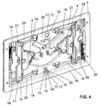
- a circumferential flange 26 of the mounting frame as this in the Figures 2 and 4 can be recognized, the said level 10 ready.
- the mounting frame 2 comprises according to the FIG. 4 essentially an interior 27, which is bounded by a rear wall 28 and peripheral side walls 29.
- the side walls 29 then joins a circumferential flange 26 at.
- the rear wall 28 furthermore comprises at least one opening 30 through which elements can be guided in the direction of the cistern.
- the actuating button 3 is preferably pivotable about at least one axis A1, A2, A3. There are essentially two different embodiments conceivable. In a first embodiment, the actuating button 3 is pivoted about exactly one axis A1. The axis A1 preferably runs centrally through the actuating button 3. In a second embodiment, the actuating button 3 is pivoted about two spaced apart axes A2, A3.
- the actuating button 3 pivots on the plane 10 at a pressure on the left area 5 and the right area 6 about the axis A1. This is a kind of rocking movement in two different directions of pivoting about the axis A1.
- the actuating button 3 pivots at a pressure on the right area 6 about the axis A2 on the plane 10 back.
- the actuating button 3 pivots about the axis A3 with respect to the plane 10th
- the operation button 3 comes to rest with the surface 11 at an angle to the plane 10.
- the actuating button 3 is pivoted about the respective axis A1 or A2 or A3 at an angle to the sheet plane.
- the leaf level according to the FIG. 1 corresponds essentially to the plane 10, which is defined by the installation arms 2 and the wall 9.
- the axes A1, A2, A3 can run both in the horizontal or in the vertical. It is also conceivable that the axes A1, A2, A3 extend at an angle or inclined to the horizontal or to the vertical.
- the dividing line 7 is then correspondingly printed in a different position in order to signal the user the direction of actuation.
- the dividing line 7 preferably runs parallel to the axes A1, A2, A3.
- the actuating button 3 is shown in a rear perspective view with the rear surface 22 clearly visible.
- the in the FIG. 3 shown actuating button 3 is suitable for use as a first embodiment with an axis A1.
- the operation key 3 for use as a second embodiment with two axes A2, A3 is in the FIGS. 6a to 6c shown and then explained further below.
- the bearing 12 preferably comprises a bearing element 14, 31 and a receiving element 13.
- the bearing element 14, 31 is formed in the receiving element 13 hooked. In the suspended state, the bearing element 14, 31 engages or protrudes into the receiving element 13, whereby the connection between the bearing element 14, 31 and receiving element 13 is provided.
- bearing element 14, 31 and receiving element 13 are at least partially matching or complementary to each other.
- the bearing element 14 may be formed sprung with a spring 17, as here the upper bearing element 14 in the FIG. 3 , or the bearing member 14 may be formed as a rigid bearing member 31, as the lower bearing member 31st
- the bearing element 14, 31 is preferably a pin 14, 31, which can be spoken by a spring-loaded bearing pin 14 in the case of the presence of the spring 17 and a rigid bearing pin 31.
- the operation button 3 can be easily hooked into the receptacles 13.
- the bearing pin 14 is pressed in a first step with the spring 17 in the corresponding receptacle 13 and the spring springs accordingly.
- the actuating button 3 can be pivoted in the direction of mounting frame 2 and also with respect to the corresponding receptacle 13 are positioned. If the installer then releases the actuating button 3, then the spring 17 and the rigid spring relax Journal 31 automatically engages in the corresponding receptacle 13 and is stored in these recordings. Thus, the installer can very easily hang the operating button 3 on the mounting frame 2.
- the bearing 12 on the mounting frame 2 in the shape of receptacles 13 and the bearing 12 on the actuating button 3 have the shape of bearing pins 14, 31.
- the bearing pins 14 protrude into the receptacles 13 and are stored there by the receptacles 13 accordingly.
- the bearing 12 on the actuating button 3 but also have the shape of receptacles 13 and then the bearing 12 is formed on the mounting frame 2 as a bearing pin 14, 31.
- the bearing pin 14 extends along an axis M. Likewise, portions of the receptacles 13 also extend along a corresponding axis M.
- the axes M extend parallel to said plane 10.
- the actuating button 3 is pivotable about this axis M.
- the axis M is substantially the axis A1 or A2, as already explained above.
- the bearing pins 14 are formed directly on the actuating button 3.
- the actuating button 3 can be injected, for example, from a plastic.
- the journals 14 may be parts of a frame 23.
- the frame 23 is connected via the rear surface 22 of the actuating button 3 with the actuating button 3 in connection.
- the actuating button 3 comprises essentially two parts, namely the actuating button 3 itself and the frame 23 which is materially connected to the actuating button 3.
- the frame 23 is preferably glued to the rear surface 22, whereby a material-locking connection between frame 23 and actuating button 3 can be provided.
- a bearing 12 preferably consists of a pair comprising a bearing pin 14, 31 and receptacle 13.
- the pairings are spaced apart from each other. In each case two pairs are arranged on a common center axis M, wherein the two bearing pins 14 and the two receptacles 13 run collinear.
- FIG. 4 can be seen that the receptacle 13 with respect to the direction of movement of the actuating button 3 from the starting position into the flushing position as a channel 15, here as an open channel 15, is formed.
- the channel 15 is thus formed in a direction perpendicular to the plane 10 seen from the actuating button 3 in the direction of mounting frame 2 open. Consequently, the bearing pin 14 can be moved in the direction of movement with respect to the fixed receptacle 13.
- the bearing pin 14 can be moved through this open channel 15.
- the channel 15 is designed to be closed to the actuating button 3, for which purpose the channel 15 has a wall 16.
- the wall 16 provides a stop for the bearing pin 14. The stop thus ensures that the actuating button 3 can not be moved from the starting position against the usual movement in the flushing position.
- the wall 16 essentially has a stop section 24, from which two wall sections 25 extend. The two wall sections 25 then preferably run parallel or at an angle or inclined to one another. In the latter case, the cross section of the open channel 15 increases in the direction from the starting position in the scavenging position.
- the angled design has the advantage that in this way the pivoting of the actuating button 3 is made possible.
- FIGS. 5a to 5c the situation in the operation of the operation button 3 according to the first embodiment will be explained.
- the operation button 3 in the starting position and in the FIG. 5c shown in the end position.
- the actuating button 3 pivots about the axis A1, which extends perpendicular to the drawing surface here.
- the operation button 3 pivots to the other side.
- the bearing elements 14, 31 preferably remain in the corresponding receptacle 13. Under great effort but it can still come to a movement in the direction of the channel 15 of the receptacle 13, which has the advantage that so undesirable forces can be compensated.
- the movement can be guided by means of guide elements 33 which protrude into guide openings 34.
- the guide elements 33 are pins 33 projecting from the actuating button 3, which project into the guide openings 34 in the mounting frame 2.
- Guide elements 33 and guide openings 34 are also in the Figures 3 and 4 recognizable.
- the guide elements 33 each have a stop element 32 at their ends. This stop element 32 acts on the back 35 of the mounting frame 2, so that a stop against movement from the starting position to the front, ie against the direction of normal operation towards the end position, is provided.
- the stop member 32 at the same time the pivot axis A2 ready, about which the actuating button 3 pivots to the mounting frame 2.
- the bearing element 14 is moved out of the recess 13 in the direction of the channel 15. With a pressure on the left region 5 or the right region 6, therefore, the bearing element 14 is moved out of the recess.
- the stop elements 32 arranged on the left are in contact with the rear side 35 of the mounting frame 2
- the stop elements 32 arranged on the right are in contact with the rear side 35 of the mounting frame 2 ,
- stop element 32 and the back 35 serve as a pivot bearing or pivot about which the actuating button is pivoted.
- the actuating button 3 can be pivoted so far until the actuating button 3 is present with the surface 11 on the wall 9 or the mounting frame 2. With the actuating button 3, the actuator element 4 is then actuated and the flushing is triggered.
- the actuator 1 additionally has an optional operating lever 19.
- This actuating lever 19 acts here on the actuator element 4 with a projection 20.
- the actuating button 3 acts on the actuating lever 19, which is then correspondingly pivoted and strikes the actuator element 4.
- the return element preferably acts on this actuating lever 19 on the actuating button 3.
- the actuating lever 19 is pivotally mounted in two mounting points 21 in the mounting frame 3. If now the optional actuating lever 19 is arranged between the actuator element 4 and the actuating button 3, then the surface 11 of the actuating button 3 acts on the actuating lever 19, which is then pivoted about the corresponding bearing point 21.
- the actuating lever 19 then acts with its projection 20 on the actuator element 4, whereby the flushing is triggered.
- a return element 18 is arranged here in the shape of a plurality of leaf springs 18 between the mounting frame 2 and the actuating button 3.
- the return elements 18 act on the rear surface 22 of the actuating button 3 and are connected via the rear wall 28 with the mounting frame 2 in connection.
- the return element 18 provides a restoring force to the actuating button 3 ready.
- the operation key 3 is moved out of the scavenging position to the home position.
- the actuating button 3 then rests in accordance with the bearing point 12th
- the actuator element 4 preferably has the shape of a pneumatic pressure transducer in the present embodiment.
- a pressure pulse is generated by the pneumatic pressure transducer, which acts on a Spülventilan Aunt.
- a pressure hose can then be passed through the openings 30 in the cistern.
- the actuator element 4 it should also be noted that the actuator element 4 is arranged between the actuating button 3 and the mounting frame 2.
- the actuator element 4 is particularly preferably connected to the mounting frame 2 or is mounted in the mounting frame 2.
- the actuator 1 has the advantage that a very simple manufacture and assembly of the actuator 1 is allowed. In addition, aesthetic requirements can also be taken into account. Further, the actuator 1 is safer in use because it can not come to a snag between the operation keys and a frame.
Description
Die vorliegende Erfindung betrifft eine Betätigungsvorrichtung für ein Ablaufventil eines Spülkastens nach dem Oberbegriff von Anspruch 1.The present invention relates to an operating device for a drain valve of a cistern according to the preamble of
Aus dem Stand der Technik sind Betätigungsvorrichtungen für Ablaufventile von Spülkästen bekannt. Beispielsweise zeigt die
Die Betätigungsvorrichtung nach
Aufgrund der Tatsache, dass die Tasten in der Abdeckplatte gelagert sind, ist der Montageaufwand bzw. der Herstellaufwand einer solchen Abdeckplatte relativ hoch. Weiter wird eine relativ genaue Positionierung zwischen Abdeckplatte und Rahmen gefordert, so dass die Tasten auf das Aktuatorelement wirken. Zudem können die Tasten mit der Abdeckplatte verhaken, was zu Funktionsstörungen führt.Due to the fact that the keys are mounted in the cover plate, the assembly effort or the manufacturing cost of such a cover plate is relatively high. Furthermore, a relatively accurate positioning between the cover plate and the frame is required, so that the keys act on the actuator element. In addition, the keys can get caught with the cover plate, resulting in malfunction.
Die
Ausgehend von diesem Stand der Technik liegt der Erfindung eine Aufgabe zugrunde, eine eingangs genannte Betätigungsvorrichtung anzugeben, welche einfacher herstellbar bzw. montierbar ist. Zudem soll die Betätigungsvorrichtung bei der Spülauslösung sicherer zu betreiben sein.Based on this prior art, the invention has for its object to provide an actuating device mentioned above, which is easier to manufacture or assemble. In addition, the actuator should be safer to operate when flushing.
Die Betätigungsvorrichtung für ein Ablaufventil eines Spülkastens umfasst bzw. beinhaltet einen Einbaurahmen, eine Betätigungstaste und mindestens ein Aktuatorelement zur Betätigung des Ablaufventils im Spülkasten, welches Aktuatorelement mit der Betätigungstaste betätigbar ist. Der Einbaurahmen wird im Betrieb in eine Maueröffnung in einer Wand eingelassen. Das Aktuatorelement ist bevorzugt zwischen dem Einbaurahmen und der Betätigungstaste angeordnet. Die Betätigungstaste ist bezüglich des Einbaurahmens bei der Spülauslösung von einer Ausgangsstellung in eine Endstellung bewegbar, insbesondere verschwenkbar, ausgebildet Die Betätigungstaste ist direkt und unmittelbar am Einbaurahmen gelagert. Mit anderen Worten kann auch gesagt werden. dass die Betätigungstaste direkt, also unmittelbar, mit dem Einbaurahmen in Verbindung steht.The actuating device for a drain valve of a cistern comprises or includes a mounting frame, an actuating button and at least one actuator element for actuating the drain valve in the cistern, which actuator element can be actuated with the actuating button. The mounting frame is inserted in operation in a wall opening in a wall. The actuator element is preferably arranged between the mounting frame and the actuating button. The actuating button is movable with respect to the mounting frame in the Spülauslösung from a starting position to an end position, in particular pivotable, formed The actuating button is directly and directly mounted on the mounting frame. In other words, it can also be said. that the actuating button is directly, ie directly, in communication with the mounting frame.
Durch die direkte Lagerung der Betätigungstaste im in der Wand einzulassenden Einbaurahmen entfällt die Lagerung der Betätigungstaste in einer separat ausgebildeten Abdeckplatte oder Betätigungsplatte, was für die Herstellung äusserst vorteilhaft ist. Weiter kann bei der Herstellung Material eingespart werden, weil auf diese Abdeckplatte verzichtetet werden kann.Due to the direct storage of the actuating button in the wall to be inserted mounting frame eliminates the storage of the actuating button in a separately formed cover plate or actuator plate, which is extremely advantageous for the production. Next can be saved in the production of material, because this cover plate can be dispensed with.
Der Einbaurahmen definiert eine Ebene, wobei die Betätigungstaste um mindestens eine Achse, die parallel zur Ebene verläuft, zur dieser Ebene verschwenkbar ist. In einer ersten bevorzugten Ausführungsform ist die Betätigungstaste um genau eine Achse verschwenkbar, welche mittig zur Betätigungstaste liegt, wobei hier von einer Wippbewegung gesprochen werden kann. In einer zweiten bevorzugten Ausführungsform ist die Betätigungstaste um genau zwei beabstandet zueinander angeordnete Achsen verschwenkbar. Hierdurch können bei beiden Ausführungsformen zwei Aktuatorelemente betätigt werden, so dass eine Zweimengenspülung auslösbar ist.The mounting frame defines a plane, wherein the actuating button is pivotable about at least one axis which is parallel to the plane to this plane. In a first preferred embodiment, the actuating button is pivotable about exactly one axis, which is located centrally to the actuating button, which can be spoken here of a rocking motion. In a second preferred embodiment, the actuating button is pivotable about exactly two spaced apart axes. In this way, in both embodiments, two actuator elements can be actuated, so that a dual-flush can be triggered.
Der Einbaurahmen und die Betätigungstaste stehen über mindestens eine Lagerstelle miteinander in Verbindung, wobei pro Achse insbesondere jeweils zwei beabstandet zueinander angeordnete Lagerstellen angeordnet sind.The mounting frame and the actuating button are connected to each other via at least one bearing point, wherein in each case two spaced bearing points are arranged per axis in particular.
Die besagte Lagerstelle umfasst ein Aufnahmeelement und ein Lagerelement, wobei das Lagerelement in das Aufnahmeelement einhängbar ausgebildet ist. Das Lagerelement ist in einer Ausbildung mit einer Feder gefedert ausgebildet und in einer anderen Ausbildung ist das Lagerelement starr ausgebildet. Pro Achse ist jeweils ein Lagerelement gefedert und das andere Lagerelement starr ausgebildet.Said bearing point comprises a receiving element and a bearing element, wherein the bearing element is designed to be hooked into the receiving element. The bearing element is sprung trained in a design with a spring and in another embodiment, the bearing element is rigid. One bearing element is sprung per axle and the other bearing element is rigidly formed.
Das Lagerelement ist bevorzugt ein Lagerzapfen, wobei der Lagerzapfen in die entsprechende Aufnahme bzw. in den Einbaurahmen einhängbar ist.The bearing element is preferably a bearing pin, wherein the bearing pin can be suspended in the corresponding receptacle or in the mounting frame.
Vorzugsweise weisen die Lagerstellen am Einbaurahmen die Gestalt von Aufnahmen und die Lagerstellen an der Betätigungstaste die Gestalt von Lagerzapfen auf, wobei die Lagerzapfen in die Aufnahmen einragen. Alternativ oder zusätzlich weisen die Lagerstellen an der Betätigungstaste die Gestalt von Aufnahmen auf und die Lagerstellen am Einbaurahmen weisen die Gestalt von Lagerzapfen auf, wobei die Lagerzapfen in die Aufnahmen einragen.Preferably, the bearing points on the mounting frame, the shape of recordings and the bearing points on the actuating button on the shape of bearing pin, wherein the bearing pins protrude into the receptacles. Alternatively or additionally, the bearing points on the actuating button on the shape of recordings and the bearing points on the mounting frame have the shape of bearing pin, wherein the bearing pins protrude into the receptacles.
Bevorzugterweise sind zwei Lagerstellen vorhanden, die eine einzige Achse definieren, vorhanden. Alternativ sind vier Lagerstellen, die zwei Achsen definieren, vorhanden.Preferably, there are two bearings that define a single axis. Alternatively, there are four bearings defining two axes.
Vorzugsweise verfügen Betätigungstaste und/oder der Einbaurahmen über mindestens ein Führungselement, wobei das Führungselement die Bewegung zwischen Betätigungstaste und Einbaurahmen führt. Das Führungselement ragt beispielsweise in eine Führungsöffnung an der Betätigungstaste bzw. am Einbaurahmen ein.Preferably, the actuating button and / or the mounting frame have at least one guide element, wherein the guide element guides the movement between the actuating button and mounting frame. The guide element projects, for example, into a guide opening on the actuating button or on the mounting frame.
Vorzugsweise verfügt das Führungselement über ein Anschlagselement, welches am Einbaurahmen eingreift, so dass eine Bewegung der Betätigungstaste von der Ausgangsstellung entgegen der Richtung zur Endstellung, blockierbar ist, wobei mit dem Anschlagselement, das am Einbaurahmen ansteht, besagte Achse bereitstellbar ist. Folglich wird dann die Betätigungstaste um das Anschlagselement verschwenkt.Preferably, the guide element has a stop element, which engages the mounting frame, so that a movement of the actuating button from the starting position against the direction of the end position, can be blocked, said with the stop member, which is present on the mounting frame, said axis is providable. consequently then the actuating button is pivoted about the stop element.
Vorzugsweise umfasst die Betätigungsvorrichtung genau eine einzige Betätigungstaste. Besonders bevorzugt ist die Betätigungstaste als ebene Platte ausgebildet. Die ebene Platte ist bevorzugt einstückig ausgebildet.Preferably, the actuating device comprises exactly one single actuating button. Particularly preferably, the actuating button is designed as a flat plate. The flat plate is preferably formed in one piece.
Die Betätigungstaste ist in einer Richtung senkrecht auf die Betätigungstaste gesehen grösser als der Einbaurahmen, so dass der Einbaurahmen in besagte Richtung gesehen im Wesentlichen vollständig durch die Betätigungstaste überdeckt ist. Weiter überdeckt die Betätigungstaste dann auch die Maueröffnung. Der Benutzer nimmt im Gebrauch im Wesentlichen nur die Betätigungstaste der Betätigungsvorrichtung war, was einen ausserordentlich hohen ästhetischen Wert hat.The actuating button is seen in a direction perpendicular to the actuating button larger than the mounting frame, so that the mounting frame seen in said direction is substantially completely covered by the operation button. Next, the operation button then covers the wall opening. The user, in use, is essentially only the operating button of the operating device, which has an extremely high aesthetic value.
Vorzugsweise ist mindestens ein Rückstellelement zwischen dem Einbaurahmen der Betätigungstaste angeordnet, wobei das Rückstellelement eine Rückstellkraft auf die Betätigungstaste bereitstellt, so dass die Betätigungstaste in die Lagerstelle bzw. die Aufnahme bewegt wird. Besonders bevorzugt sind mehrere Rückstellelemente angeordnet, so dass die Betätigungstaste parallel zum Einbaurahmen zu liegen kommt.Preferably, at least one return element is arranged between the mounting frame of the actuating button, wherein the restoring element provides a restoring force on the actuating button, so that the actuating button is moved into the bearing or the recording. More preferably, a plurality of return elements are arranged so that the actuating button comes to lie parallel to the mounting frame.
Bevorzugterweise weist die Betätigungsvorrichtung weiter mindestens einen Betätigungshebel auf, welcher mit der Betätigungstaste betätigbar ist und auf das Aktuatorelement wirkt. Vorzugsweise wirkt das Rückstellelement über den Betätigungshebel auf die Betätigungstaste.Preferably, the actuating device further comprises at least one actuating lever, which is actuated by the actuating button and acts on the actuator element. Preferably, the return element acts on the actuating lever on the actuating lever.
Weitere Ausführungsformen sind in den abhängigen Ansprüchen angegeben.Further embodiments are given in the dependent claims.
Bevorzugte Ausführungsformen der Erfindung werden im Folgenden anhand der Zeichnungen beschrieben, die lediglich zur Erläuterung dienen und nicht einschränkend auszulegen sind. In den Zeichnungen zeigen:
- Fig. 1
- eine Frontansicht einer Betätigungsvorrichtung gemäss einer
- Fig. 2
- Ausführungsform der vorliegenden Erfindung; eine Seitenansicht der Betätigungsvorrichtung nach
Figur 1 - Fig. 3
- eine perspektivische Ansicht einer Betätigungstaste gemäss der Betätigungsvorrichtung nach
Figur 1 - Fig. 4
- eine perspektivische Ansicht eines Einbaurahmens oder eines Rahmenelementes zur Aufnahme der Betätigungstaste gemäss der Betätigungsvorrichtung nach
Figur 1 - Fig. 5a bis 5c
- eine Seitenansicht und zwei Schnittansichten entlang der Schnittlinie VI-VI gemäss der
Figur 1 - Fig. 6a bis 6c
- eine Seitenansicht und zwei Schnittansichten entlang der Schnittlinie VI-VI gemäss der
Figur 1 mit Führungselementen einer zweiten Ausführungsform - Fig. 7
- eine Schnittansicht gemäss der
Figur 1 entlang der Schnittlinie V-V nachFigur 1 .
- Fig. 1
- a front view of an actuator according to a
- Fig. 2
- Embodiment of the present invention; a side view of the actuator according to
FIG. 1 ; - Fig. 3
- a perspective view of an actuating button according to the actuator according to
FIG. 1 from the back; - Fig. 4
- a perspective view of a mounting frame or a frame member for receiving the actuating button according to the actuating device according to
FIG. 1 from the front; - Fig. 5a to 5c
- a side view and two sectional views along the section line VI-VI according to the
FIG. 1 with guide elements of a first embodiment; and - Fig. 6a to 6c
- a side view and two sectional views along the section line VI-VI according to the
FIG. 1 with guide elements of a second embodiment - Fig. 7
- a sectional view according to the
FIG. 1 along the section line VV toFIG. 1 ,
In der
In der Ausführungsform nach der
Die Betätigungstaste 3 ist vorzugsweise als ebene Platte mit einer vorderen Oberfläche 11 und einer hinteren Oberfläche 22 ausgebildet. Besonders bevorzugt ist die Betätigungstaste 3 im Wesentlichen einstückig ausgebildet.The
Vorzugsweise umfasst die Betätigungsvorrichtung 1 genau eine einzige Betätigungstaste 3. Somit kann eine besonders einfache Ausbildung der Betätigungsvorrichtung bei der Möglichkeit der Auslösung einer Zweimengenspülung bereitgestellt werden.Preferably, the
Von der
Die Betätigungstaste 3 ist bezüglich des Einbaurahmens 2 bei der Spülauslösung von einer Ausgangsstellung in eine Endstellung bewegbar, insbesondere verschwenkbar, ausgebildet. Folglich kann also die Betätigungstaste 3 von der Ausgangsstellung bei der Betätigung zum Einbaurahmen 2 hin in die Endstellung bewegt werden. Nach erfolgter Spülung wird dann die Betätigungstaste 3 vom Einbaurahmen 2 weg, also von der Endstellung in die Ausgangsstellung bewegt.The
Der Einbaurahmen 2 wird typischerweise in eine Öffnung in einem Mauerwerk eingelassen und steht mit Elementen des Spülkastens in Verbindung. Die Maueröffnung 8 ist in der
Mit Bezug zu der
Auch von der
Der Einbaurahmen 2 bzw. die Wand 9 definieren eine Ebene 10. Die Ebene 10 verläuft dabei im Wesentlichen parallel zur Wand 9 und kann durch entsprechende Elemente des Einbaurahmens 2 definiert werden. Beispielsweise stellt ein umlaufender Flansch 26 des Einbaurahmens, wie dieser in den
Der Einbaurahmen 2 umfasst gemäss der
Die Betätigungstaste 3 ist bevorzugt um mindestens eine Achse A1, A2, A3 verschwenkbar. Es sind dabei im Wesentlichen zwei verschiedene Ausführungsformen denkbar. In einer ersten Ausführungsform wird die Betätigungstaste 3 um genau eine Achse A1 verschwenkt. Die Achse A1 verläuft dabei bevorzugt mittig durch die Betätigungstaste 3. In einer zweiten Ausführungsform wird die Betätigungstaste 3 um zwei beabstandet zueinander angeordnete Achsen A2, A3 verschwenkt.The
In der
Bei einer Betätigung kommt die Betätigungstaste 3 mit der Oberfläche 11 winklig zur Ebene 10 zu liegen. Mit Blick auf
Die Achsen A1, A2, A3 können dabei sowohl in der Horizontalen oder in der Vertikalen verlaufen. Auch ist es denkbar, dass die Achsen A1, A2, A3 winklig bzw. geneigt zur Horizontalen bzw. zur Vertikalen verlaufen. Der Trennstrich 7 wird dann entsprechend in einer anderen Lage aufgedruckt, um dem Benutzer die Richtung der Betätigung zu signalisieren. Der Trennstrich 7 verläuft dabei vorzugsweise parallel zu den Achsen A1, A2, A3.The axes A1, A2, A3 can run both in the horizontal or in the vertical. It is also conceivable that the axes A1, A2, A3 extend at an angle or inclined to the horizontal or to the vertical. The
In der
Von den
Die Lagerstelle 12 umfasst bevorzugt ein Lagerelement 14, 31 und ein Aufnahmeelement 13. Das Lagerelement 14, 31 ist dabei in das Aufnahmeelement 13 einhängbar ausgebildet. Im eingehängten Zustand greift oder ragt das Lagerelement 14, 31 in das Aufnahmeelement 13 ein, wodurch die Verbindung zwischen Lagerelement 14, 31 und Aufnahmeelement 13 bereitgestellt wird. Für diesen Eingriff sind Lagerelement 14, 31 und Aufnahmeelement 13 mindestens teilweise passend oder komplementär zueinander ausgebildet.The bearing 12 preferably comprises a bearing
Das Lagerelement 14 kann dabei mit einer Feder 17 gefedert ausgebildet sein, wie hier das obere Lagerelement 14 in der
Das Lagerelement 14, 31 ist bevorzugterweise ein Zapfen 14, 31, wobei von einem gefederten Lagerzapfen 14 im Falle des Vorhandenseins der Feder 17 und von einem starren Lagerzapfen 31 gesprochen werden kann. Durch die Feder kann die Betätigungstaste 3 einfach in die Aufnahmen 13 eingehängt werden.The bearing
Unter Bezugnahme auf die
In der vorliegenden Ausführungsform weist die Lagerstelle 12 am Einbaurahmen 2 die Gestalt von Aufnahmen 13 auf und die Lagerstelle 12 an der Betätigungstaste 3 weisen die Gestalt von Lagerzapfen 14, 31 auf. Die Lagerzapfen 14 ragen dabei in die Aufnahmen 13 ein und werden dort durch die Aufnahmen 13 entsprechend gelagert. In alternativen Ausführungsformen kann die Lagerstelle 12 an der Betätigungstaste 3 aber auch die Gestalt von Aufnahmen 13 aufweisen und dann ist die Lagerstelle 12 am Einbaurahmen 2 als Lagerzapfen 14, 31 ausgebildet.In the present embodiment, the bearing 12 on the mounting
Der Lagerzapfen 14 erstreckt sich entlang einer Achse M. Ebenfalls erstrecken sich auch Abschnitte der Aufnahmen 13 entlang einer entsprechenden Achse M. Die Achsen M verlaufen dabei parallel zu besagter Ebene 10. Die Betätigungstaste 3 ist dabei um diese Achse M verschwenkbar. Die Achse M wird dabei im Wesentlichen zur Achse A1 bzw. A2, so wie die oben bereits erläutert wurde.The bearing
Je nach Material sind die Lagerzapfen 14 direkt an der Betätigungstaste 3 angeformt. Die Betätigungstaste 3 kann beispielsweise aus einem Kunststoff gespritzt werden. Alternativ, beispielsweise wenn die Betätigungstaste 3 aus Glas oder einem anderen Material als Kunststoff gefertigt ist, können die Lagerzapfen 14 Teile eines Rahmens 23 sein. Der Rahmen 23 steht über die hintere Oberfläche 22 der Betätigungstaste 3 mit der Betätigungstaste 3 in Verbindung. Die Betätigungstaste 3 umfasst in einer solchen Ausführungsform im Wesentlichen zwei Teile, nämlich die Betätigungstaste 3 selbst und den mit der Betätigungstaste 3 stoffschlüssig in Verbindung stehende Rahmen 23. Der Rahmen 23 wird vorzugsweise auf die hintere Oberfläche 22 aufgeklebt, wodurch eine stoffschlüssige Verbindung zwischen Rahmen 23 und Betätigungstaste 3 bereitstellbar ist. Obwohl hier die Betätigungstaste 3 über dem Rahmen 23 mit dem Einbaurahmen 2 in Verbindung steht, kann gleichwohl gesagt werden, dass die Betätigungstaste 3 direkt mit dem Einbaurahmen 2 in Verbindung steht, weil über die besagte stoffschlüssige Verbindung Betätigungstaste 3 und Rahmen 23 als einstückig anzusehen sind.Depending on the material, the bearing pins 14 are formed directly on the
Eine Lagerstelle 12 besteht vorzugsweise aus einer Paarung umfassend einen Lagerzapfen 14, 31 und Aufnahme 13. Die Paarungen sind dabei beanstandet zueinander angeordnet. Jeweils zwei Paarungen sind auf einer gemeinsamen Mittelachse M angeordnet, wobei die beiden Lagerzapfen 14 und die beiden Aufnahmen 13 kollinear verlaufen.A bearing 12 preferably consists of a pair comprising a
Von der
Der Kanal 15 ist dabei zur Betätigungstaste 3 hin geschlossen ausgebildet, wobei hierfür der Kanal 15 eine Wandung 16 aufweist. Die Wandung 16 stellt für den Lagerzapfen 14 einen Anschlag bereit. Der Anschlag sorgt somit dafür, dass die Betätigungstaste 3 nicht von der Ausgangsstellung entgegen der üblichen Bewegung in die Spülstellung bewegt werden kann. Die Wandung 16 weist im Wesentlichen einen Anschlagsabschnitt 24 auf, von welchem sich zwei Wandabschnitte 25 erstrecken. Die beiden Wandabschnitte 25 verlaufen dann vorzugsweise parallel oder winklig bzw. geneigt zueinander. Im letzteren Fall nimmt der Querschnitt des offenen Kanals 15 in der Richtung von Ausgangsstellung in Spülstellung zu.The
Die winklige Ausbildung hat dabei den Vorteil, dass hierdurch die Verschwenkbarkeit der Betätigungstaste 3 ermöglicht wird.The angled design has the advantage that in this way the pivoting of the
Anhand der
Bei dieser Betätigung verbleiben die Lagerelemente 14, 31 vorzugsweise in der entsprechenden Aufnahme 13. Unter grossem Kraftaufwand kann es aber dennoch zu einer Bewegung in Richtung des Kanals 15 der Aufnahme 13 kommen, was den Vorteil hat, dass so unerwünschte Kräfte kompensierbar sind.In this operation, the bearing
Die Bewegung kann über Führungselemente 33 die in Führungsöffnungen 34 einragen, unterstützend geführt werden. Bei dem Führungselemente 33 handelt es sich um von der Betätigungstaste 3 abstehende Dorne 33, welche in die Führungsöffnungen 34 im Einbaurahmen 2 hineinragen. Führungselemente 33 und Führungsöffnungen 34 sind auch in den
Anhand der
Weiter stellt das Anschlagselement 32 zugleich die Verschwenkachse A2 bereit, um welche sich die Betätigungstaste 3 zum Einbaurahmen 2 verschwenkt. Bei der Verschwenkung in dieser Ausführungsform wird das Lagerelement 14 aus der Ausnehmung 13 hinaus in Richtung des Kanals 15 bewegt. Bei einem Druck auf den linken Bereich 5 oder den rechten Bereich 6 wird also das Lagerelement 14 aus der Ausnehmung bewegt. Bei einem Druck auf den rechten Bereich 6 stehen dabei die links angeordneten Anschlagselemente 32 mit der Rückseite 35 des Einbaurahmenes 2 in Kontakt und bei einem Druck auf den linken Bereich 5 stehen dabei die rechts angeordneten Anschlagselemente 32 mit mit der Rückseite 35 des Einbaurahmenes 2 in Kontakt.Next, the
Folglich dienen die Anschlagselement 32 und die Rückseite 35 dabei als Schwenklager bzw. Drehpunkt, um welchen die Betätigungstaste verschwenkt wird.Consequently, the
Bei beiden Ausführungsformen kann die Betätigungstaste 3 soweit verschwenkt werden, bis die Betätigungstaste 3 mit der Oberfläche 11 an der Wand 9 oder am Einbaurahmen 2 ansteht. Mit der Betätigungstaste 3 wird dann das Aktuatorelement 4 betätigt und die Spülung wird ausgelöst.In both embodiments, the
Weiter kann von der
Die Rückstellung der Betätigungstaste 3 von der Spülstellung in die Ausgangsstellung erfolgt dann über die Rückstellelemente 18. Von der
Das Rückstellelement 18 stellt dabei eine Rückstellkraft auf die Betätigungstaste 3 bereit. Somit wird die Betätigungstaste 3 aus der Spülposition hinaus in die Ausgangsstellung bewegt. In der Ausgangsstellung ruht die Betätigungstaste 3 dann entsprechend in der Lagerstelle 12.The
Das Aktuatorelement 4 weist in der vorliegenden Ausführungsform vorzugweise die Gestalt eines pneumatischen Druckgebers auf. Dabei wird vom pneumatischen Druckgeber ein Druckpuls generiert, welcher auf eine Spülventilanordnung wirkt. Ein Druckschlauch kann dann über die Öffnungen 30 in den Spülkasten geführt werden. Bezüglich des Aktuatorelementes 4 sei weiter angemerkt, dass das Aktuatorelement 4 zwischen der Betätigungstaste 3 und dem Einbaurahmen 2 angeordnet ist. Besonders bevorzugt steht das Aktuatorelement 4 mit dem Einbaurahmen 2 in Verbindung bzw. wird im Einbaurahmen 2 gelagert.The
Zusammenfassend weist die Betätigungsvorrichtung 1 den Vorteil auf, dass eine äusserst einfache Herstellung und Montage der Betätigungsvorrichtung 1 erlaubt wird. Zudem können ästhetischen Anforderungen ebenfalls Rechnung getragen werden. Weiter ist die Betätigungsvorrichtung 1 sicherer im Gebrauch, weil es nicht zu einem verhaken zwischen den Betätigungstasten und einem Rahmen kommen kann.
Claims (13)
- An actuator device (1) for a drain valve in a bathroom cistern comprising or including a mounting frame (2), an actuator button (3) and at least one actuator element (4) for the actuation of the drain valve in the bathroom cistern, which actuator element (4) can be actuated with the actuator button (3),
wherein when flushing, the actuator button (3) is pivotable from an initial position in a final position with respect to the mounting frame (2), wherein the actuator button (3) is mounted directly and immediately on the mounting frame (2),
wherein the mounting frame (2) defines a plane (10), wherein the actuator button (3) is pivotable about at least one axle (A1, A2, A3), that runs parallel to the plane (10),
wherein the mounting frame (2) and the actuator button (3) are connected to one another by means of bearing positions (12), wherein at each axle (A1, A2, A3) there are two bearing positions (12) arranged that are spaced apart from one another, which bearing positions (12) comprise each a receiving element (13) and a bearing element (14, 31), characterized
in that each bearing element (14) is shaped and sized to be hooked in a receiving element (13), wherein a bearing element (14) of the one bearing position (12) is provided spring-suspended with a spring (17) and wherein the bearing element (31) of the other bearing position (12) is provided rigidly. - The actuator device according to claim 1, characterized in that each bearing element (14, 31) is a bearing journal (14, 31), wherein the bearing journal (14, 31) can be hooked in the corresponding reception (13) or in the mounting frame (2) respectively.
- The actuator device according to claim 2, characterized in that the bearing journals (14, 31) are assigned to the actuator button (3) and the receptions (13) are assigned to the mounting frame (2).
- The actuator device according to claim 2, characterized in that the bearing journals (14, 31) are assigned to the mounting frame (2) and the receptions (13) are assigned to the actuator button (3).
- The actuator device according to one of claims 2 to 4, characterized in that the bearing journal (14) extends along an axis (M) and in that the reception (13) extends along said axis (M), wherein the axis (M) runs parallel to said plane (10) and wherein the actuator button (3) is pivotable about said axis (M).
- The actuator device according to one of the preceding claims, characterized in that two bearing positions (12) are present that define a single axis (A1), or in that four bearing positions (12) are present that define two axis (A1, A2).
- The actuator device according to one of claims 2 to 6, characterized in that the receiving element (13) is formed as a channel (15) from the initial position to the final position with respect to the direction of motion of the actuator button (3), wherein, upon actuation, the bearing journal (14, 31) is movable through said open channel (15), and wherein the channel (15) is preferably closed with a wall (16) towards the actuator button (3) and therefore provides a stop for the bearing journal (14).
- The actuator device according to one of the preceding claims, characterized in that the actuator button (3) and/or the mounting frame (2) are provided with at least one guiding element (33), wherein the guiding element (33) guides the movement between actuator button (3) and mounting frame (2).
- The actuator device according to claim 8, characterized in that the guiding element (33) is provided with a stop element (32), which engages the mounting frame (2), so that a movement of the actuator button (3) is blocked from the initial position in a direction opposite to the final position, wherein one of said axis (A1, A2, A3) is defined by the stop element.
- The actuator device according to one of the preceding claims, characterized in that the actuator button (3) is pivotable about a first axle (A1) that runs parallel to the plane (10) and additionally the actuator button (3) is pivotable about a second axle (A2) that runs parallel to the plane and the first axle (A1).
- The actuator device according to one of the preceding claims, characterized in that the actuator device (1) encompasses exactly one single actuator button (3) and/or in that the actuator button (3) is designed as a flat plate and/or the actuator button (3) is bigger as the mounting frame (2) in a direction perpendicular viewed on the actuator button (3), so that the mounting frame (2) is completely covered by the actuator button (3), viewed in said direction.
- The actuator device according to one of the preceding claims, characterized in that at least one restoring element (18) is arranged between the mounting frame (2) and the actuator button (3), wherein the restoring element (18) provides a restoring force on the actuator button (3), so that the actuator button (3) is moved to the resting position (12) or is moved from the final position to the initial position respectively.
- The actuator device according to one of the preceding claims, characterized in that the actuator device (1) further comprises at least one actuator lever (19), which can be actuated by the actuator button (3) and acts on the actuator element (4) and/or in that the restoring element (18) acts on the actuator button (3) via the actuator lever (19).
Priority Applications (2)
| Application Number | Priority Date | Filing Date | Title |
|---|---|---|---|
| EP12171285.5A EP2672029B1 (en) | 2012-06-08 | 2012-06-08 | Actuator device for a drain valve in a bathroom cistern |
| DK12171285.5T DK2672029T3 (en) | 2012-06-08 | 2012-06-08 | Activation device for a discharge valve in a toilet cistern |
Applications Claiming Priority (1)
| Application Number | Priority Date | Filing Date | Title |
|---|---|---|---|
| EP12171285.5A EP2672029B1 (en) | 2012-06-08 | 2012-06-08 | Actuator device for a drain valve in a bathroom cistern |
Publications (2)
| Publication Number | Publication Date |
|---|---|
| EP2672029A1 EP2672029A1 (en) | 2013-12-11 |
| EP2672029B1 true EP2672029B1 (en) | 2016-05-11 |
Family
ID=46245895
Family Applications (1)
| Application Number | Title | Priority Date | Filing Date |
|---|---|---|---|
| EP12171285.5A Active EP2672029B1 (en) | 2012-06-08 | 2012-06-08 | Actuator device for a drain valve in a bathroom cistern |
Country Status (2)
| Country | Link |
|---|---|
| EP (1) | EP2672029B1 (en) |
| DK (1) | DK2672029T3 (en) |
Citations (2)
| Publication number | Priority date | Publication date | Assignee | Title |
|---|---|---|---|---|
| GB2391257A (en) * | 2002-07-30 | 2004-02-04 | Leaderflush & Shapland Ltd | Bi-fold door assembly |
| FR2883902A1 (en) * | 2005-04-05 | 2006-10-06 | Lamberet Const Isothermes Sa | Opening frame e.g. insulated container door, and framework articulation device, has rods movable in hole between deployed position, in which rods project outside body, and retracted position, in which rods are housed in hole |
Family Cites Families (5)
| Publication number | Priority date | Publication date | Assignee | Title |
|---|---|---|---|---|
| ITMI20031323A1 (en) | 2003-06-27 | 2004-12-28 | Valsir Spa | CONTROL DEVICE OF THE DISCHARGE VALVE OF A RINSE BOX. |
| DE202006012664U1 (en) * | 2006-08-17 | 2007-12-27 | Viega Gmbh & Co. Kg | Actuating device for a urinal flush-mounted or concealed toilet cistern |
| DE202006013003U1 (en) * | 2006-08-24 | 2008-01-03 | Viega Gmbh & Co. Kg | Device for the manual actuation of a concealed, flush-mounted or concealed flush valve |
| DE202006013850U1 (en) * | 2006-09-07 | 2008-01-10 | Viega Gmbh & Co. Kg | Actuating device for a sanitary object, in particular for a toilet cistern |
| PL2388380T3 (en) * | 2010-05-20 | 2014-03-31 | Geberit Int Ag | Actuation device for actuating the rinsing of a sanitary apparatus and method for fitting such an actuating device |
-
2012
- 2012-06-08 EP EP12171285.5A patent/EP2672029B1/en active Active
- 2012-06-08 DK DK12171285.5T patent/DK2672029T3/en active
Patent Citations (2)
| Publication number | Priority date | Publication date | Assignee | Title |
|---|---|---|---|---|
| GB2391257A (en) * | 2002-07-30 | 2004-02-04 | Leaderflush & Shapland Ltd | Bi-fold door assembly |
| FR2883902A1 (en) * | 2005-04-05 | 2006-10-06 | Lamberet Const Isothermes Sa | Opening frame e.g. insulated container door, and framework articulation device, has rods movable in hole between deployed position, in which rods project outside body, and retracted position, in which rods are housed in hole |
Also Published As
| Publication number | Publication date |
|---|---|
| EP2672029A1 (en) | 2013-12-11 |
| DK2672029T3 (en) | 2016-08-22 |
Similar Documents
| Publication | Publication Date | Title |
|---|---|---|
| EP2796650B1 (en) | Furniture hinge | |
| EP2411612B1 (en) | Furniture hinge | |
| DE102016006388B4 (en) | Valve operating device and method for switching a valve arrangement | |
| DE102015106917B4 (en) | Furniture hinge with a damper and a spring | |
| DE102011001512A1 (en) | donor | |
| EP2476808B1 (en) | Actuation device for a cistern | |
| EP3551808B1 (en) | Pressurised water valve | |
| EP2554075A1 (en) | Chair with a rocking mechanism | |
| DE102017126366A1 (en) | Flap fitting for a furniture, side wall of a furniture body and furniture with a side wall | |
| EP2388379B1 (en) | Actuation device for a cistern | |
| AT11541U1 (en) | HINGE | |
| AT508069B1 (en) | FURNITURE HINGE | |
| EP2620575B1 (en) | Opening aid for a window, door or the like, and a corresponding window | |
| EP2672029B1 (en) | Actuator device for a drain valve in a bathroom cistern | |
| EP2672030B1 (en) | Actuator device for a drain valve for a sanitary bathroom cistern | |
| EP3342966B1 (en) | Hinge for pivoting a door | |
| EP2787133B1 (en) | Sanitary fixtures | |
| DE202014104103U1 (en) | Floor drain, especially in the bottom of a kitchen sink | |
| EP2072696B1 (en) | Actuating device for flushing tank | |
| EP2894265B1 (en) | Pneumatic actuation device | |
| DE202006012654U1 (en) | Release mechanism for an adjustable pillar and the like, e.g. for an office chair seat, has an operating unit to release the gas spring blocking the pillar setting to give a new height level | |
| CH705437B1 (en) | Remote control unit and latching mechanism for a remote control unit. | |
| DE202008013833U1 (en) | toilet seat | |
| EP2913449B1 (en) | Flush actuation device and assembly with a flushing tank for a toilet or urinal | |
| EP2716825B1 (en) | Cistern with hydraulic actuation |
Legal Events
| Date | Code | Title | Description |
|---|---|---|---|
| PUAI | Public reference made under article 153(3) epc to a published international application that has entered the european phase |
Free format text: ORIGINAL CODE: 0009012 |
|
| AK | Designated contracting states |
Kind code of ref document: A1 Designated state(s): AL AT BE BG CH CY CZ DE DK EE ES FI FR GB GR HR HU IE IS IT LI LT LU LV MC MK MT NL NO PL PT RO RS SE SI SK SM TR |
|
| AX | Request for extension of the european patent |
Extension state: BA ME |
|
| 17P | Request for examination filed |
Effective date: 20140415 |
|
| RBV | Designated contracting states (corrected) |
Designated state(s): AL AT BE BG CH CY CZ DE DK EE ES FI FR GB GR HR HU IE IS IT LI LT LU LV MC MK MT NL NO PL PT RO RS SE SI SK SM TR |
|
| 17Q | First examination report despatched |
Effective date: 20140729 |
|
| GRAP | Despatch of communication of intention to grant a patent |
Free format text: ORIGINAL CODE: EPIDOSNIGR1 |
|
| INTG | Intention to grant announced |
Effective date: 20151119 |
|
| GRAS | Grant fee paid |
Free format text: ORIGINAL CODE: EPIDOSNIGR3 |
|
| GRAA | (expected) grant |
Free format text: ORIGINAL CODE: 0009210 |
|
| AK | Designated contracting states |
Kind code of ref document: B1 Designated state(s): AL AT BE BG CH CY CZ DE DK EE ES FI FR GB GR HR HU IE IS IT LI LT LU LV MC MK MT NL NO PL PT RO RS SE SI SK SM TR |
|
| REG | Reference to a national code |
Ref country code: GB Ref legal event code: FG4D Free format text: NOT ENGLISH |
|
| REG | Reference to a national code |
Ref country code: CH Ref legal event code: EP |
|
| REG | Reference to a national code |
Ref country code: AT Ref legal event code: REF Ref document number: 798798 Country of ref document: AT Kind code of ref document: T Effective date: 20160515 |
|
| REG | Reference to a national code |
Ref country code: IE Ref legal event code: FG4D Free format text: LANGUAGE OF EP DOCUMENT: GERMAN |
|
| REG | Reference to a national code |
Ref country code: CH Ref legal event code: NV Representative=s name: ISLER AND PEDRAZZINI AG, CH |
|
| REG | Reference to a national code |
Ref country code: FR Ref legal event code: PLFP Year of fee payment: 5 |
|
| REG | Reference to a national code |
Ref country code: DE Ref legal event code: R096 Ref document number: 502012007055 Country of ref document: DE |
|
| REG | Reference to a national code |
Ref country code: NL Ref legal event code: FP |
|
| REG | Reference to a national code |
Ref country code: DK Ref legal event code: T3 Effective date: 20160819 |
|
| REG | Reference to a national code |
Ref country code: LT Ref legal event code: MG4D |
|
| PG25 | Lapsed in a contracting state [announced via postgrant information from national office to epo] |
Ref country code: NO Free format text: LAPSE BECAUSE OF FAILURE TO SUBMIT A TRANSLATION OF THE DESCRIPTION OR TO PAY THE FEE WITHIN THE PRESCRIBED TIME-LIMIT Effective date: 20160811 Ref country code: LT Free format text: LAPSE BECAUSE OF FAILURE TO SUBMIT A TRANSLATION OF THE DESCRIPTION OR TO PAY THE FEE WITHIN THE PRESCRIBED TIME-LIMIT Effective date: 20160511 Ref country code: FI Free format text: LAPSE BECAUSE OF FAILURE TO SUBMIT A TRANSLATION OF THE DESCRIPTION OR TO PAY THE FEE WITHIN THE PRESCRIBED TIME-LIMIT Effective date: 20160511 |
|
| PG25 | Lapsed in a contracting state [announced via postgrant information from national office to epo] |
Ref country code: LV Free format text: LAPSE BECAUSE OF FAILURE TO SUBMIT A TRANSLATION OF THE DESCRIPTION OR TO PAY THE FEE WITHIN THE PRESCRIBED TIME-LIMIT Effective date: 20160511 Ref country code: RS Free format text: LAPSE BECAUSE OF FAILURE TO SUBMIT A TRANSLATION OF THE DESCRIPTION OR TO PAY THE FEE WITHIN THE PRESCRIBED TIME-LIMIT Effective date: 20160511 Ref country code: ES Free format text: LAPSE BECAUSE OF FAILURE TO SUBMIT A TRANSLATION OF THE DESCRIPTION OR TO PAY THE FEE WITHIN THE PRESCRIBED TIME-LIMIT Effective date: 20160511 Ref country code: GR Free format text: LAPSE BECAUSE OF FAILURE TO SUBMIT A TRANSLATION OF THE DESCRIPTION OR TO PAY THE FEE WITHIN THE PRESCRIBED TIME-LIMIT Effective date: 20160812 Ref country code: HR Free format text: LAPSE BECAUSE OF FAILURE TO SUBMIT A TRANSLATION OF THE DESCRIPTION OR TO PAY THE FEE WITHIN THE PRESCRIBED TIME-LIMIT Effective date: 20160511 Ref country code: SE Free format text: LAPSE BECAUSE OF FAILURE TO SUBMIT A TRANSLATION OF THE DESCRIPTION OR TO PAY THE FEE WITHIN THE PRESCRIBED TIME-LIMIT Effective date: 20160511 Ref country code: PT Free format text: LAPSE BECAUSE OF FAILURE TO SUBMIT A TRANSLATION OF THE DESCRIPTION OR TO PAY THE FEE WITHIN THE PRESCRIBED TIME-LIMIT Effective date: 20160912 |
|
| PG25 | Lapsed in a contracting state [announced via postgrant information from national office to epo] |
Ref country code: RO Free format text: LAPSE BECAUSE OF FAILURE TO SUBMIT A TRANSLATION OF THE DESCRIPTION OR TO PAY THE FEE WITHIN THE PRESCRIBED TIME-LIMIT Effective date: 20160511 Ref country code: SK Free format text: LAPSE BECAUSE OF FAILURE TO SUBMIT A TRANSLATION OF THE DESCRIPTION OR TO PAY THE FEE WITHIN THE PRESCRIBED TIME-LIMIT Effective date: 20160511 Ref country code: EE Free format text: LAPSE BECAUSE OF FAILURE TO SUBMIT A TRANSLATION OF THE DESCRIPTION OR TO PAY THE FEE WITHIN THE PRESCRIBED TIME-LIMIT Effective date: 20160511 Ref country code: CZ Free format text: LAPSE BECAUSE OF FAILURE TO SUBMIT A TRANSLATION OF THE DESCRIPTION OR TO PAY THE FEE WITHIN THE PRESCRIBED TIME-LIMIT Effective date: 20160511 |
|
| REG | Reference to a national code |
Ref country code: DE Ref legal event code: R097 Ref document number: 502012007055 Country of ref document: DE |
|
| PG25 | Lapsed in a contracting state [announced via postgrant information from national office to epo] |
Ref country code: SM Free format text: LAPSE BECAUSE OF FAILURE TO SUBMIT A TRANSLATION OF THE DESCRIPTION OR TO PAY THE FEE WITHIN THE PRESCRIBED TIME-LIMIT Effective date: 20160511 Ref country code: PL Free format text: LAPSE BECAUSE OF FAILURE TO SUBMIT A TRANSLATION OF THE DESCRIPTION OR TO PAY THE FEE WITHIN THE PRESCRIBED TIME-LIMIT Effective date: 20160511 |
|
| PLBE | No opposition filed within time limit |
Free format text: ORIGINAL CODE: 0009261 |
|
| STAA | Information on the status of an ep patent application or granted ep patent |
Free format text: STATUS: NO OPPOSITION FILED WITHIN TIME LIMIT |
|
| REG | Reference to a national code |
Ref country code: IE Ref legal event code: MM4A |
|
| PG25 | Lapsed in a contracting state [announced via postgrant information from national office to epo] |
Ref country code: MC Free format text: LAPSE BECAUSE OF FAILURE TO SUBMIT A TRANSLATION OF THE DESCRIPTION OR TO PAY THE FEE WITHIN THE PRESCRIBED TIME-LIMIT Effective date: 20160511 |
|
| 26N | No opposition filed |
Effective date: 20170214 |
|
| PG25 | Lapsed in a contracting state [announced via postgrant information from national office to epo] |
Ref country code: SI Free format text: LAPSE BECAUSE OF FAILURE TO SUBMIT A TRANSLATION OF THE DESCRIPTION OR TO PAY THE FEE WITHIN THE PRESCRIBED TIME-LIMIT Effective date: 20160511 Ref country code: IE Free format text: LAPSE BECAUSE OF NON-PAYMENT OF DUE FEES Effective date: 20160608 |
|
| REG | Reference to a national code |
Ref country code: FR Ref legal event code: PLFP Year of fee payment: 6 |
|
| PG25 | Lapsed in a contracting state [announced via postgrant information from national office to epo] |
Ref country code: CY Free format text: LAPSE BECAUSE OF FAILURE TO SUBMIT A TRANSLATION OF THE DESCRIPTION OR TO PAY THE FEE WITHIN THE PRESCRIBED TIME-LIMIT Effective date: 20160511 Ref country code: HU Free format text: LAPSE BECAUSE OF FAILURE TO SUBMIT A TRANSLATION OF THE DESCRIPTION OR TO PAY THE FEE WITHIN THE PRESCRIBED TIME-LIMIT; INVALID AB INITIO Effective date: 20120608 |
|
| REG | Reference to a national code |
Ref country code: FR Ref legal event code: PLFP Year of fee payment: 7 |
|
| PG25 | Lapsed in a contracting state [announced via postgrant information from national office to epo] |
Ref country code: MK Free format text: LAPSE BECAUSE OF FAILURE TO SUBMIT A TRANSLATION OF THE DESCRIPTION OR TO PAY THE FEE WITHIN THE PRESCRIBED TIME-LIMIT Effective date: 20160511 Ref country code: MT Free format text: LAPSE BECAUSE OF FAILURE TO SUBMIT A TRANSLATION OF THE DESCRIPTION OR TO PAY THE FEE WITHIN THE PRESCRIBED TIME-LIMIT Effective date: 20160511 Ref country code: TR Free format text: LAPSE BECAUSE OF FAILURE TO SUBMIT A TRANSLATION OF THE DESCRIPTION OR TO PAY THE FEE WITHIN THE PRESCRIBED TIME-LIMIT Effective date: 20160511 Ref country code: IS Free format text: LAPSE BECAUSE OF FAILURE TO SUBMIT A TRANSLATION OF THE DESCRIPTION OR TO PAY THE FEE WITHIN THE PRESCRIBED TIME-LIMIT Effective date: 20160511 Ref country code: LU Free format text: LAPSE BECAUSE OF NON-PAYMENT OF DUE FEES Effective date: 20160608 |
|
| PG25 | Lapsed in a contracting state [announced via postgrant information from national office to epo] |
Ref country code: BG Free format text: LAPSE BECAUSE OF FAILURE TO SUBMIT A TRANSLATION OF THE DESCRIPTION OR TO PAY THE FEE WITHIN THE PRESCRIBED TIME-LIMIT Effective date: 20160511 |
|
| PG25 | Lapsed in a contracting state [announced via postgrant information from national office to epo] |
Ref country code: AL Free format text: LAPSE BECAUSE OF FAILURE TO SUBMIT A TRANSLATION OF THE DESCRIPTION OR TO PAY THE FEE WITHIN THE PRESCRIBED TIME-LIMIT Effective date: 20160511 |
|
| PGFP | Annual fee paid to national office [announced via postgrant information from national office to epo] |
Ref country code: NL Payment date: 20210618 Year of fee payment: 10 |
|
| PGFP | Annual fee paid to national office [announced via postgrant information from national office to epo] |
Ref country code: DK Payment date: 20210623 Year of fee payment: 10 Ref country code: CH Payment date: 20210611 Year of fee payment: 10 Ref country code: BE Payment date: 20210618 Year of fee payment: 10 Ref country code: AT Payment date: 20210621 Year of fee payment: 10 |
|
| REG | Reference to a national code |
Ref country code: DK Ref legal event code: EBP Effective date: 20220630 |
|
| REG | Reference to a national code |
Ref country code: CH Ref legal event code: PL |
|
| REG | Reference to a national code |
Ref country code: NL Ref legal event code: MM Effective date: 20220701 |
|
| REG | Reference to a national code |
Ref country code: AT Ref legal event code: MM01 Ref document number: 798798 Country of ref document: AT Kind code of ref document: T Effective date: 20220608 |
|
| REG | Reference to a national code |
Ref country code: BE Ref legal event code: MM Effective date: 20220630 |
|
| PG25 | Lapsed in a contracting state [announced via postgrant information from national office to epo] |
Ref country code: NL Free format text: LAPSE BECAUSE OF NON-PAYMENT OF DUE FEES Effective date: 20220701 |
|
| PG25 | Lapsed in a contracting state [announced via postgrant information from national office to epo] |
Ref country code: LI Free format text: LAPSE BECAUSE OF NON-PAYMENT OF DUE FEES Effective date: 20220630 Ref country code: CH Free format text: LAPSE BECAUSE OF NON-PAYMENT OF DUE FEES Effective date: 20220630 Ref country code: AT Free format text: LAPSE BECAUSE OF NON-PAYMENT OF DUE FEES Effective date: 20220608 |
|
| PG25 | Lapsed in a contracting state [announced via postgrant information from national office to epo] |
Ref country code: BE Free format text: LAPSE BECAUSE OF NON-PAYMENT OF DUE FEES Effective date: 20220630 |
|
| P01 | Opt-out of the competence of the unified patent court (upc) registered |
Effective date: 20230516 |
|
| PG25 | Lapsed in a contracting state [announced via postgrant information from national office to epo] |
Ref country code: DK Free format text: LAPSE BECAUSE OF NON-PAYMENT OF DUE FEES Effective date: 20220630 |
|
| PGFP | Annual fee paid to national office [announced via postgrant information from national office to epo] |
Ref country code: FR Payment date: 20230627 Year of fee payment: 12 Ref country code: DE Payment date: 20230620 Year of fee payment: 12 |
|
| PGFP | Annual fee paid to national office [announced via postgrant information from national office to epo] |
Ref country code: IT Payment date: 20230621 Year of fee payment: 12 Ref country code: GB Payment date: 20230622 Year of fee payment: 12 |