EP2671709B1 - Non-vented bladder system for curing composite parts - Google Patents
Non-vented bladder system for curing composite parts Download PDFInfo
- Publication number
- EP2671709B1 EP2671709B1 EP13169023.2A EP13169023A EP2671709B1 EP 2671709 B1 EP2671709 B1 EP 2671709B1 EP 13169023 A EP13169023 A EP 13169023A EP 2671709 B1 EP2671709 B1 EP 2671709B1
- Authority
- EP
- European Patent Office
- Prior art keywords
- bladder
- reservoir
- fluid
- fluid reservoir
- flexible
- Prior art date
- Legal status (The legal status is an assumption and is not a legal conclusion. Google has not performed a legal analysis and makes no representation as to the accuracy of the status listed.)
- Active
Links
Images


Classifications
-
- B—PERFORMING OPERATIONS; TRANSPORTING
- B29—WORKING OF PLASTICS; WORKING OF SUBSTANCES IN A PLASTIC STATE IN GENERAL
- B29C—SHAPING OR JOINING OF PLASTICS; SHAPING OF MATERIAL IN A PLASTIC STATE, NOT OTHERWISE PROVIDED FOR; AFTER-TREATMENT OF THE SHAPED PRODUCTS, e.g. REPAIRING
- B29C35/00—Heating, cooling or curing, e.g. crosslinking or vulcanising; Apparatus therefor
- B29C35/02—Heating or curing, e.g. crosslinking or vulcanizing during moulding, e.g. in a mould
- B29C35/04—Heating or curing, e.g. crosslinking or vulcanizing during moulding, e.g. in a mould using liquids, gas or steam
-
- B—PERFORMING OPERATIONS; TRANSPORTING
- B29—WORKING OF PLASTICS; WORKING OF SUBSTANCES IN A PLASTIC STATE IN GENERAL
- B29C—SHAPING OR JOINING OF PLASTICS; SHAPING OF MATERIAL IN A PLASTIC STATE, NOT OTHERWISE PROVIDED FOR; AFTER-TREATMENT OF THE SHAPED PRODUCTS, e.g. REPAIRING
- B29C35/00—Heating, cooling or curing, e.g. crosslinking or vulcanising; Apparatus therefor
- B29C35/02—Heating or curing, e.g. crosslinking or vulcanizing during moulding, e.g. in a mould
-
- B—PERFORMING OPERATIONS; TRANSPORTING
- B29—WORKING OF PLASTICS; WORKING OF SUBSTANCES IN A PLASTIC STATE IN GENERAL
- B29C—SHAPING OR JOINING OF PLASTICS; SHAPING OF MATERIAL IN A PLASTIC STATE, NOT OTHERWISE PROVIDED FOR; AFTER-TREATMENT OF THE SHAPED PRODUCTS, e.g. REPAIRING
- B29C70/00—Shaping composites, i.e. plastics material comprising reinforcements, fillers or preformed parts, e.g. inserts
- B29C70/04—Shaping composites, i.e. plastics material comprising reinforcements, fillers or preformed parts, e.g. inserts comprising reinforcements only, e.g. self-reinforcing plastics
- B29C70/28—Shaping operations therefor
- B29C70/40—Shaping or impregnating by compression not applied
- B29C70/42—Shaping or impregnating by compression not applied for producing articles of definite length, i.e. discrete articles
- B29C70/44—Shaping or impregnating by compression not applied for producing articles of definite length, i.e. discrete articles using isostatic pressure, e.g. pressure difference-moulding, vacuum bag-moulding, autoclave-moulding or expanding rubber-moulding
- B29C70/446—Moulding structures having an axis of symmetry or at least one channel, e.g. tubular structures, frames
-
- B—PERFORMING OPERATIONS; TRANSPORTING
- B29—WORKING OF PLASTICS; WORKING OF SUBSTANCES IN A PLASTIC STATE IN GENERAL
- B29C—SHAPING OR JOINING OF PLASTICS; SHAPING OF MATERIAL IN A PLASTIC STATE, NOT OTHERWISE PROVIDED FOR; AFTER-TREATMENT OF THE SHAPED PRODUCTS, e.g. REPAIRING
- B29C33/00—Moulds or cores; Details thereof or accessories therefor
- B29C33/10—Moulds or cores; Details thereof or accessories therefor with incorporated venting means
-
- B—PERFORMING OPERATIONS; TRANSPORTING
- B29—WORKING OF PLASTICS; WORKING OF SUBSTANCES IN A PLASTIC STATE IN GENERAL
- B29C—SHAPING OR JOINING OF PLASTICS; SHAPING OF MATERIAL IN A PLASTIC STATE, NOT OTHERWISE PROVIDED FOR; AFTER-TREATMENT OF THE SHAPED PRODUCTS, e.g. REPAIRING
- B29C33/00—Moulds or cores; Details thereof or accessories therefor
- B29C33/38—Moulds or cores; Details thereof or accessories therefor characterised by the material or the manufacturing process
- B29C33/40—Plastics, e.g. foam or rubber
- B29C33/405—Elastomers, e.g. rubber
-
- B—PERFORMING OPERATIONS; TRANSPORTING
- B29—WORKING OF PLASTICS; WORKING OF SUBSTANCES IN A PLASTIC STATE IN GENERAL
- B29C—SHAPING OR JOINING OF PLASTICS; SHAPING OF MATERIAL IN A PLASTIC STATE, NOT OTHERWISE PROVIDED FOR; AFTER-TREATMENT OF THE SHAPED PRODUCTS, e.g. REPAIRING
- B29C33/00—Moulds or cores; Details thereof or accessories therefor
- B29C33/44—Moulds or cores; Details thereof or accessories therefor with means for, or specially constructed to facilitate, the removal of articles, e.g. of undercut articles
- B29C33/48—Moulds or cores; Details thereof or accessories therefor with means for, or specially constructed to facilitate, the removal of articles, e.g. of undercut articles with means for collapsing or disassembling
- B29C33/485—Moulds or cores; Details thereof or accessories therefor with means for, or specially constructed to facilitate, the removal of articles, e.g. of undercut articles with means for collapsing or disassembling cores or mandrels
-
- B—PERFORMING OPERATIONS; TRANSPORTING
- B29—WORKING OF PLASTICS; WORKING OF SUBSTANCES IN A PLASTIC STATE IN GENERAL
- B29C—SHAPING OR JOINING OF PLASTICS; SHAPING OF MATERIAL IN A PLASTIC STATE, NOT OTHERWISE PROVIDED FOR; AFTER-TREATMENT OF THE SHAPED PRODUCTS, e.g. REPAIRING
- B29C33/00—Moulds or cores; Details thereof or accessories therefor
- B29C33/44—Moulds or cores; Details thereof or accessories therefor with means for, or specially constructed to facilitate, the removal of articles, e.g. of undercut articles
- B29C33/48—Moulds or cores; Details thereof or accessories therefor with means for, or specially constructed to facilitate, the removal of articles, e.g. of undercut articles with means for collapsing or disassembling
- B29C33/50—Moulds or cores; Details thereof or accessories therefor with means for, or specially constructed to facilitate, the removal of articles, e.g. of undercut articles with means for collapsing or disassembling elastic or flexible
- B29C33/505—Moulds or cores; Details thereof or accessories therefor with means for, or specially constructed to facilitate, the removal of articles, e.g. of undercut articles with means for collapsing or disassembling elastic or flexible cores or mandrels, e.g. inflatable
-
- B—PERFORMING OPERATIONS; TRANSPORTING
- B29—WORKING OF PLASTICS; WORKING OF SUBSTANCES IN A PLASTIC STATE IN GENERAL
- B29C—SHAPING OR JOINING OF PLASTICS; SHAPING OF MATERIAL IN A PLASTIC STATE, NOT OTHERWISE PROVIDED FOR; AFTER-TREATMENT OF THE SHAPED PRODUCTS, e.g. REPAIRING
- B29C35/00—Heating, cooling or curing, e.g. crosslinking or vulcanising; Apparatus therefor
-
- B—PERFORMING OPERATIONS; TRANSPORTING
- B29—WORKING OF PLASTICS; WORKING OF SUBSTANCES IN A PLASTIC STATE IN GENERAL
- B29C—SHAPING OR JOINING OF PLASTICS; SHAPING OF MATERIAL IN A PLASTIC STATE, NOT OTHERWISE PROVIDED FOR; AFTER-TREATMENT OF THE SHAPED PRODUCTS, e.g. REPAIRING
- B29C43/00—Compression moulding, i.e. applying external pressure to flow the moulding material; Apparatus therefor
- B29C43/32—Component parts, details or accessories; Auxiliary operations
- B29C43/36—Moulds for making articles of definite length, i.e. discrete articles
- B29C43/3642—Bags, bleeder sheets or cauls for isostatic pressing
-
- B—PERFORMING OPERATIONS; TRANSPORTING
- B29—WORKING OF PLASTICS; WORKING OF SUBSTANCES IN A PLASTIC STATE IN GENERAL
- B29C—SHAPING OR JOINING OF PLASTICS; SHAPING OF MATERIAL IN A PLASTIC STATE, NOT OTHERWISE PROVIDED FOR; AFTER-TREATMENT OF THE SHAPED PRODUCTS, e.g. REPAIRING
- B29C65/00—Joining or sealing of preformed parts, e.g. welding of plastics materials; Apparatus therefor
- B29C65/78—Means for handling the parts to be joined, e.g. for making containers or hollow articles, e.g. means for handling sheets, plates, web-like materials, tubular articles, hollow articles or elements to be joined therewith; Means for discharging the joined articles from the joining apparatus
-
- B—PERFORMING OPERATIONS; TRANSPORTING
- B29—WORKING OF PLASTICS; WORKING OF SUBSTANCES IN A PLASTIC STATE IN GENERAL
- B29C—SHAPING OR JOINING OF PLASTICS; SHAPING OF MATERIAL IN A PLASTIC STATE, NOT OTHERWISE PROVIDED FOR; AFTER-TREATMENT OF THE SHAPED PRODUCTS, e.g. REPAIRING
- B29C43/00—Compression moulding, i.e. applying external pressure to flow the moulding material; Apparatus therefor
- B29C43/32—Component parts, details or accessories; Auxiliary operations
- B29C43/36—Moulds for making articles of definite length, i.e. discrete articles
- B29C43/3642—Bags, bleeder sheets or cauls for isostatic pressing
- B29C2043/3649—Inflatable bladders using gas or fluid and related details
-
- B—PERFORMING OPERATIONS; TRANSPORTING
- B29—WORKING OF PLASTICS; WORKING OF SUBSTANCES IN A PLASTIC STATE IN GENERAL
- B29K—INDEXING SCHEME ASSOCIATED WITH SUBCLASSES B29B, B29C OR B29D, RELATING TO MOULDING MATERIALS OR TO MATERIALS FOR MOULDS, REINFORCEMENTS, FILLERS OR PREFORMED PARTS, e.g. INSERTS
- B29K2105/00—Condition, form or state of moulded material or of the material to be shaped
- B29K2105/06—Condition, form or state of moulded material or of the material to be shaped containing reinforcements, fillers or inserts
-
- B—PERFORMING OPERATIONS; TRANSPORTING
- B29—WORKING OF PLASTICS; WORKING OF SUBSTANCES IN A PLASTIC STATE IN GENERAL
- B29K—INDEXING SCHEME ASSOCIATED WITH SUBCLASSES B29B, B29C OR B29D, RELATING TO MOULDING MATERIALS OR TO MATERIALS FOR MOULDS, REINFORCEMENTS, FILLERS OR PREFORMED PARTS, e.g. INSERTS
- B29K2821/00—Use of unspecified rubbers as mould material
-
- B—PERFORMING OPERATIONS; TRANSPORTING
- B29—WORKING OF PLASTICS; WORKING OF SUBSTANCES IN A PLASTIC STATE IN GENERAL
- B29K—INDEXING SCHEME ASSOCIATED WITH SUBCLASSES B29B, B29C OR B29D, RELATING TO MOULDING MATERIALS OR TO MATERIALS FOR MOULDS, REINFORCEMENTS, FILLERS OR PREFORMED PARTS, e.g. INSERTS
- B29K2867/00—Use of polyesters or derivatives thereof as mould material
-
- B—PERFORMING OPERATIONS; TRANSPORTING
- B29—WORKING OF PLASTICS; WORKING OF SUBSTANCES IN A PLASTIC STATE IN GENERAL
- B29L—INDEXING SCHEME ASSOCIATED WITH SUBCLASS B29C, RELATING TO PARTICULAR ARTICLES
- B29L2031/00—Other particular articles
- B29L2031/30—Vehicles, e.g. ships or aircraft, or body parts thereof
- B29L2031/3076—Aircrafts
-
- Y—GENERAL TAGGING OF NEW TECHNOLOGICAL DEVELOPMENTS; GENERAL TAGGING OF CROSS-SECTIONAL TECHNOLOGIES SPANNING OVER SEVERAL SECTIONS OF THE IPC; TECHNICAL SUBJECTS COVERED BY FORMER USPC CROSS-REFERENCE ART COLLECTIONS [XRACs] AND DIGESTS
- Y02—TECHNOLOGIES OR APPLICATIONS FOR MITIGATION OR ADAPTATION AGAINST CLIMATE CHANGE
- Y02T—CLIMATE CHANGE MITIGATION TECHNOLOGIES RELATED TO TRANSPORTATION
- Y02T50/00—Aeronautics or air transport
- Y02T50/40—Weight reduction
Definitions
- the present disclosure generally relates to methods and equipment for fabricating composite resin parts, and deals more particularly with a bladder system used in curing composite parts within an autoclave.
- Composite resin parts may be cured within an autoclave that applies heat and pressure to the part during a cure cycle.
- Some part geometries include internal cavities that may cause the part to collapse under autoclave pressure unless a tool such as an inflatable bladder is placed in the cavity to react the autoclave pressure force applied to the part.
- inflatable bladders may be inserted into the cavities of composite stringer layups that are autoclave cured on mandrel-like cure tools. These bladders are pressurized by venting them to the autoclave pressure.
- a non-vented bladder system may reduce or eliminate the adverse effects resulting from leaks in the bladder or failure to properly pressurize the bladder.
- a bladder system and curing method that does not require venting to autoclave pressure, and which may eliminate the need for bladder vent hole seals.
- WO 2009/020466 discloses a complex-shaped, three-dimensional fiber reinforced composite structure which may be formed by using counteracting pressures applied to a structural lay-up of fiber plies.
- the fiber plies are arranged on a pressurizable member that may become an integral part of the final product, or may be removed before the product is finalized.
- the pressurizable member may take the form of a hollow blow molded or rotomolded thermoplastic component or a superplastic formed metallic component having an opening such that the pressurizable member may be vented or pressurized and thus expanded against the fiber plies.
- the disclosed embodiments provide a non-vented bladder system that may substantially reduce or eliminate inconsistencies in cured parts due to bladder leakage, seal leakage and/or or failure of a bladder to properly vent to autoclave pressures.
- the disclosed system may reduce product scrap and/or the need for rework. Additionally, the disclosed method and non-vented bladder system may reduce labor costs and improve production flow.
- the embodiments eliminate the need for use of a sealant tape around a vent hole in the bladder.
- a fluid reservoir is permanently attached to the bladder vent hole and is sealed beneath a vacuum bag, thereby eliminating leak paths around the bladder vent. The reservoir pressurizes the bladder cavity when the autoclave is pressurized. In the event of a leak in the bladder, only the volume of the bladder is leaked into the part.
- an apparatus for use in autoclave curing of a composite part charge having an internal cavity.
- the apparatus comprises a flexible bladder adapted to be placed in the cavity for applying pressure on the composite part charge during the curing, a reservoir of fluid for pressuring the bladder, the reservoir and the bladder being coupled together in a closed system and a flexible bag sealed over the flexible bladder and the fluid reservoir.
- the flexible bag is in face-to-face contact with the fluid reservoir.
- the flexible bag may transmit pressure from the autoclave to the fluid reservoir.
- the apparatus may also comprise a cure tool adapted to have the composite part charge placed thereon, and wherein the fluid reservoir is located on the cure tool and the flexible bag is sealed to the cured tool.
- the fluid reservoir may be flexible.
- the bladder may include a vent hole, and a portion of the fluid reservoir may be attached to the bladder and include a fluid outlet coupled with the vent hole in the bladder.
- the fluid reservoir may include a vacuum port sealed beneath the flexible bag adapted to be coupled with a vacuum source for selectively relieving pressure within the fluid reservoir after the composite charge has been cured.
- the bladder may include a septum forming an interior chamber within the bladder, and a fill material filling the interior chamber which has a density that is sufficient to stiffen the bladder when the bladder is pressured by fluid from the fluid reservoir.
- the septum may include a flexible side that is exposed to fluid from the fluid reservoir. The flexible side may flex to apply pressure to the fill material when the fluid reservoir pressurizes the bladder.
- a non-vented bladder system for use in autoclave curing a composite part charge.
- the non-vented bladder system comprises a bladder adapted to apply pressure to the composite part charge, and a flexible fluid reservoir adapted to contain a quantity of fluid and compressible by pressure applied by the autoclave for supplying fluid pressure to the bladder, wherein the fluid reservoir is coupled with the bladder in a closed fluid system that is not vented to the autoclave.
- the fluid reservoir is attached to the bladder.
- the fluid reservoir includes a fluid outlet, and the bladder includes a vent hole coupled with the fluid outlet.
- the bladder includes flexible septum exposed to fluid from the fluid reservoir forming an internal chamber within the bladder, and a fill material within the internal chamber for stiffening the bladder.
- apparatus for applying substantially uniform external air pressure on an uncured part having an internal cavity.
- the apparatus comprises a tool adapted to have the part placed thereon, a bladder adapted to be placed within the internal cavity and in contact with the part, the bladder being adapted to be pressurized with a fluid, a reservoir of the fluid coupled with the bladder, and a flexible bag sealed to the tool and covering the part, the bladder and the reservoir.
- the reservoir is attached to the bladder to form a single assembly that may be installed in and removed from the internal cavity.
- the reservoir includes flexible walls in face-to-face contact with the flexible bag allowing the external pressure to be applied to the reservoir through the flexible bag.
- the bladder includes fill material for stiffening the bladder, and a septum separating the fill material from the reservoir fluid. The reservoir and the bladder form a closed fluid system that is not vented to the external pressure.
- a method is provided of autoclave curing a composite part charge having an internal cavity.
- the method comprises placing the composite part charge on a tool, installing a bladder within the cavity, coupling the bladder with a reservoir of fluid in a closed system, sealing a flexible bag over the part and the reservoir in face-to-face contact with the reservoir of fluid, and using the flexible bag to transmit autoclave pressure to the reservoir to force fluid from the reservoir into the bladder.
- Coupling the bladder with the reservoir may include attaching the bladder to the reservoir before the bladder is installed in the cavity. Sealing the bag may include sealing the bag to the tool.
- the method may further comprise stiffening the bladder by filling the bladder with a fill material, and separating the fill material from the fluid by placing a septum in the bladder.
- the method may also comprise using a vacuum to draw the flexible bag down against sides of the reservoir.
- a method is provided of autoclave curing a composite part charge having an internal cavity.
- the method comprises supporting the composite part charge within the autoclave, and pressurizing a bladder within the internal cavity using autoclave pressure to force fluid from a fluid reservoir into the bladder.
- Using the autoclave pressure to force the fluid from the fluid reservoir into the bladder includes evacuating a vacuum bag sealed over the fluid reservoir, and using the bag to transmit the autoclave pressure to the fluid reservoir.
- an apparatus for use in autoclave curing of a composite charge having an internal cavity including a flexible bladder adapted to be placed in the cavity for applying pressure on the composite charge during the curing; and a reservoir of fluid for pressuring the bladder, the reservoir and the bladder being coupled together in a closed system.
- the apparatus may further including a flexible bag sealed over the flexible bladder and the fluid reservoir, and wherein the flexible bag may be in face-to-face contact with the fluid reservoir.
- the apparatus wherein the flexible bag may transmit pressure from the autoclave to the fluid reservoir.
- the apparatus may further include a cure tool adapted to have the composite charge placed thereon, and wherein the fluid reservoir may be located on the cure tool and the flexible bag is sealed to the cured tool.
- the fluid reservoir may be flexible.
- the bladder may include a vent hole, and a portion of the fluid reservoir may be attached to the bladder and include a fluid outlet coupled with the vent hole in the bladder.
- the reservoir may include a vacuum port adapted to be coupled with a vacuum source for selectively relieving pressure within the fluid reservoir.
- the bladder may include a septum forming an interior chamber within the bladder, and a fill material may fill the interior chamber and have a density that is sufficient to stiffen the bladder when the bladder is pressured by fluid from the fluid reservoir.
- the septum may include a flexible side that is exposed to fluid from the fluid of the fluid reservoir, and the flexible side may flex to apply pressure to the fill material when the fluid reservoir pressurizes the bladder.
- a non-vented bladder system for use in autoclave curing a composite part charge, including a bladder adapted to apply pressure to the composite part charge; and a flexible fluid reservoir adapted to contain a quality of fluid and compressible by pressure applied by the autoclave for supplying fluid pressure to the bladder, wherein the fluid reservoir is coupled with the bladder in a closed fluid system that is not vented to the autoclave.
- the fluid reservoir may be attached to the bladder.
- the fluid reservoir may include a fluid outlet, and the bladder includes a vent hole coupled with the fluid outlet.
- the bladder may include a flexible septum exposed to fluid from the fluid reservoir forming an internal chamber within the bladder, and a fill material within the internal chamber for stiffening the bladder.
- an apparatus for applying substantially uniform external air pressure on a part having an internal cavity including a tool adapted to have the part placed thereon; a bladder adapted to be placed within the internal cavity and in contact with the part, the bladder being adapted to be pressurized with a fluid; a reservoir of the fluid coupled with the bladder; and a flexible bag sealed to the tool and covering the part, the bladder and the reservoir.
- the reservoir may be attached to the bladder to form a single assembly that may be installed in and removed from the internal cavity.
- the reservoir may include flexible walls in face-to-face contact with the flexible bag allowing the external pressure to be applied to the reservoir through the flexible bag.
- the bladder may include fill material for stiffening the bladder, and a septum separating the fill material from the reservoir fluid.
- the reservoir and the bladder may form a closed fluid system that is not vented to the external pressure.
- a method of autoclave curing a composite charge having an internal cavity including placing the composite charge on a tool; installing a bladder within the cavity; coupling the bladder with a reservoir of fluid; sealing a flexible bag over the composite charge and the reservoir; and using the flexible bag to transmit autoclave pressure to the reservoir to force fluid from the reservoir into the bladder.
- Coupling the bladder with the reservoir may include attaching the bladder to the reservoir before the bladder is installed in the cavity.
- Sealing the bag may include sealing the bag to the tool.
- the method may further include stiffening the bladder by filling the bladder with a fill material, and separating the fill material from the fluid by placing a septum in the bladder.
- the method may further include using a vacuum to draw the flexible bag down against sides of the reservoir.
- the method may further include removing the flexible bag from the composite charge and the reservoir after the composite charge has been cured; and relieving pressure within the bladder by porting the reservoir to a vacuum source after the flexible bag has been removed.
- a method of autoclave curing a composite part charge having an internal cavity including supporting the composite part charge within the autoclave; and pressurizing a bladder within the internal cavity using autoclave pressure to force fluid from a fluid reservoir into the bladder.
- Using the autoclave pressure to force the fluid from the fluid reservoir into the bladder may include evacuating a vacuum bag sealed over the fluid reservoir, and using the bag to transmit the autoclave pressure to the fluid reservoir.
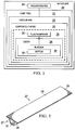
- an uncured composite resin part 20 hereafter referred to as a "charge”, a “composite charge”, a “composite part charge” or a “stringer charge”, is cured on a cure tool 22 placed in an autoclave 26 in which autoclave heat and pressure are applied to the composite charge 20.
- the composite charge 20 includes one or more internal voids, trapped or enclosed areas, or cavities, which for ease of description, will collectively be referred hereinafter as a cavity 28.
- a flexible, inflatable bladder 30 is placed within the cavity 28 prior to a cure cycle in order to react autoclave pressures applied to the charge 20 during curing.
- a flexible fluid reservoir 32 is mounted on the cure tool 22 and is coupled with the bladder 30 in an manner that forms a closed bladder system 25 which is not vented to the atmosphere within the autoclave 26.
- the bladder 30 and the fluid reservoir 32 form a closed fluid system that is not directly exposed to the internal atmosphere of the autoclave 26.
- a flexible bag such as a vacuum bag 24, is placed over and sealed to the cure tool 22, covering the composite charge 20, the bladder 30 and the fluid reservoir 32.
- the flexible bag 24 is adapted to be coupled with a suitable vacuum source 64 for evacuating the flexible bag 24.
- the bladder 30 is pressurized using a substantially non-compressible fluid (not shown) supplied from the fluid reservoir 32.
- the bladder 30 is not vented to the internal atmosphere of the autoclave 26, i.e. the bladder 30 is non-vented. Rather, the combination of the bladder 30 and the fluid reservoir 32 form a closed, non-vented bladder system 25 that is controlled by autoclave air pressure exerted on the vacuum bag 24.
- the bladder 30 may include an internal septum 35 that separates substantially the full internal volume of the bladder 30 from the fluid supplied from the fluid reservoir 32. Reduction of the pressure within the fluid reservoir 32 allows the bladder 30 to partially collapse slightly, thereby preventing the bladder 30 from becoming "locked” in the composite charge 20 and facilitating easy removal of the bladder 30 from the cured composite charge 20.
- the disclosed non-vented bladder system and curing method may be employed to cure any of a variety of composite resin parts of various geometries, having one or more internal cavities.
- the disclosed system and method may be used in the fabrication of a fiber reinforced composite resin stringer 23, which may comprise a muli-ply layup of prepreg.
- the stringer 23 includes a hat section 27 forming an internal cavity 31, a pair of laterally extending flange sections 29 and a substantially flat skin section 33 that is consolidated together with the flange sections 29 during curing.
- Other stringer geometries are possible.
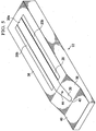
- FIGS. 3-10 respectively illustrate successive stages in the preparation of the apparatus shown in FIG. 1 for curing of the stringer 23 shown in FIG. 2 .
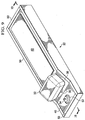
- a cure tool 22 made of any suitable material includes an internal cavity 28 defining a hat section tool face 32, and a pair of laterally extending, flange section tool faces 34. Tool faces 32, 34 are configured to respectively match the geometry of the hat section and flange sections 27, 29 respectively of the stringer 23.
- the cure tool 22 has a substantially flat upper tool surface 36 surrounding the internal cavity 28, a chamfered surface 38 at one end of the cavity 28, and a substantially flat end section 40. One end of the internal cavity 28 is open at 42.
- the cure tool 22 may be used to assemble composite stringer charges, and to cure the assembled charges within an autoclave 26 ( FIG. 1 ). While the illustrated cure tool 22 has a geometry that is adapted to match features of the stringer 23, it should be noted that the disclosed non-vented bladder system 25 may be used with cure tools having any of various other geometries, depending on the application and the particular composite part charge to be cured.
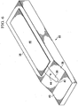
- a composite stringer charge 20 is placed on the cure tool 22.
- the stringer charge 20 comprises a hat 20a filling the cavity 28 and engaging the tool face 32 ( FIG. 3 ), and a pair of laterally extending flanges 20b respectively engaging the tool faces 34.
- the stringer charge 20 may be laid up on a separate layup tool (not shown) and then transferred to the cure tool 22, or alternatively, depending on the geometry of the part charge , it may be possible to layup the stringer directly on the cure tool 22.
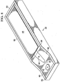
- a flexible bladder 30 is placed within the cavity 28 ( FIG. 4 ) of the stringer charge 20 in order to react autoclave pressures that are applied during a curing cycle.
- the bladder 30 may be formed of any suitable material such, for example and without limitation, an elastomer.
- a release agent may be applied to the bladder 30 before it is installed to facilitate later removal of the bladder from the cavity 28 following curing.
- the bladder 30 includes a bladder vent hole 44 that is adapted to be coupled with the fluid reservoir 32 shown in FIG 1 , as will be discussed below.
- the bladder 30 is configured to substantially match the geometry of the cavity 28 and has a substantially flat upper surface 30a that is substantially flush with the flat tool surfaces 36 of the cure tool 22.
- a substantially flat composite skin charge 46 is placed on the cure tool 22, overlying the bladder 30 and in face-to-face contact with the flanges 20b ( FIG. 5 ) of the stringer charge 20 and the flat tool surfaces 36.
- a caul plate 48 may be installed over the flat composite skin charge 46 in order to apply substantially even pressure over the skin charge 46 during the curing process.
- peel plies, release films and/or breathers or other components may be installed along with the caul plate 48, depending on the application.
- a suitable sealant tape 50 or other suitable sealant is applied to the perimeter of the cure tool 22 in preparation for vacuum bagging the tool 22.
- a vacuum probe base 52 may be applied to the flat end section 40 of the cure tool 22.
- a flexible fluid reservoir 32 is attached to the bladder 30 such that the bladder 30 and the fluid reservoir 32 may be installed and removed as a single assembly, if desired.
- the fluid reservoir 32 is coupled with the vent hole 44 ( FIG. 8 ) in the bladder 30 and is supported on the chamfered surface 38 of the cure tool 22 when the bladder 30 is in place within the composite charge cavity 28.
- the fluid reservoir 32 may be permanently attached and sealed to the bladder 30, thus obviating the need to reconnect the bladder 30 to a pressure source each time the bladder 30 is installed in a composite charge 20 in preparation for a curing process. This arrangement also eliminates the need for placing a sealant around the vent hole 44 each time the bladder is installed in a composite charge 20.
- the fluid reservoir 32 may be fabricated from any suitable material such as, without limitation, an elastomer.
- a vacuum probe 54 is mounted on the vacuum probe base 52, and is adapted to be coupled with a vacuum source (not shown) for evacuating the vacuum bag 24 during a cure cycle.
- the fluid reservoir 32 may have a generally rectangular or square cross sectional shape with sides 32a that are flexible and may plastically deform inwardly as shown by the dashed lines 32b when external pressure is applied to the fluid reservoir 32.
- a portion 32b of the fluid reservoir 32 is attached in face-to-face contact to one end of the bladder 30 and includes a fluid outlet 41 that is aligned and coupled with the vent hole 44 in the bladder 30, allowing fluid to flow between the fluid reservoir 32 and the bladder 30.
- the fluid reservoir 32 may have a different shape, and may or may not be attached to the bladder 30.
- the vacuum bag 24 is in face-to-face contact with the fluid reservoir 32.
- the vacuum bag 24 is sealed to the periphery of the cure tool 22 and around the vacuum probe 54 using sealing tape 50 or other suitable sealants. Evacuation of vacuum bag 24 draws the vacuum bag 24 down in face-to-face contact with the sides of the fluid reservoir 32, allowing autoclave pressure P A to be applied to the fluid reservoir 32.
- the fluid reservoir 32 may include a vacuum port 60 that is adapted to be coupled with a vacuum source (not shown) after the vacuum bag 24 has been removed following a cure cycle.
- the vacuum port 60 is closed and sealed beneath the vacuum bag 24 during curing, but includes a valve or other device (not shown) that allows connection of the internal volume 56 of the fluid reservoir 32 to the vacuum source after curing is completed and the vacuum bag has been removed.
- Coupling the fluid reservoir 32 to the vacuum source in this manner relieves fluid pressure within the fluid reservoir 32, which in turn reduces the pressure within the bladder 30, allowing the bladder 30 to deflate or collapse slightly. Deflation of the bladder 30 in this manner reduces the maximum cross sectional dimension (not shown) of the bladder 30 an amount that is sufficient to allow the bladder 30 to be removed from the cured stringer.
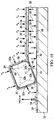
- autoclave pressure P A forces the vacuum bag 24 against the cure tool 22, thereby compacting the composite charge 20 while also applying pressure to the fluid reservoir 32.
- the autoclave pressure P A applied to the fluid reservoir 32 causes fluid to flow 45 from the internal volume 56 of the fluid reservoir 32 through the bladder vent hole 44 into the bladder 30, thereby internally pressurizing the bladder 30.
- This pressurization of the bladder 30 causes a force 55 to be applied to composite charge 20 that reacts the autoclave pressure P A applied to the composite charge 20.
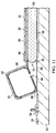
- the autoclave pressure P A is removed from the vacuum bag 22, and thus is removed from the fluid reservoir 32.
- the resulting decrease in fluid pressure within the fluid reservoir 32 allows fluid to flow from the bladder 58 through the vent hole 44 back into the fluid reservoir 32.
- the fluid reservoir 32 may be permanently sealed to the bladder 30, thus obviating the need to place a sealant around the vent hole 44 ( FIG. 8 ) each time the bladder 30 is installed in a composite charge 20. Permanently sealing the fluid reservoir 32 to the bladder 30 may therefore eliminate leakage around the vent hole 44 into the composite charge 20. In the event of a leak in either the bladder 30 or the fluid reservoir 32, fluid leakage into the composite charge 20 is limited to the total volume of the bladder 30 and the fluid reservoir 32 since the bladder system 25 ( FIG. 1 ) is a closed system and does not allow air from the autoclave to enter into the composite charge cavity 28 ( FIG. 4 ).
- the bladder 30 includes an internal septum 35 that separates the interior chamber 65 of the bladder 30 from the fluid supplied by the fluid reservoir 32.
- the septum 35 is made of a flexible material and may be formed integral with the bladder 30.
- the bladder chamber 65 is filled with a flowable fill material 66 having a relatively low CTE (coefficient of thermal expansion) and a density selected to provide the bladder 30 with a desired level of stiffness.
- One side 75 of the septum 35 is exposed to the fluid supplied by fluid reservoir 32. Fluid from the reservoir 56 that is forced against the bladder 30 by the autoclave pressure P A , exerts fluid pressure P F ( FIG.
- the volume of air within the autoclave 26 does not reach the composite charge 20, because the bladder system 25 is sealed beneath the vacuum bag 24. Rather, the total amount of fluid possibly reaching the composite charge 20 in the event of a leak in either the bladder 30 or the fluid reservoir 32 ( FIGS. 10-12 ) is limited to the fluid reservoir interior volume 56 plus the bladder chamber volume 65.
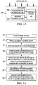
- FIG. 14 broadly illustrates the steps of a method for autoclave curing using the non-vented bladder system 25 described above.
- a composite resin charge 20 is placed on a suitable tool, which may be a cure tool.
- a flexible, inflatable bladder 30 is installed in an internal cavity 28 of the charge 20.
- the flexible bladder 30 is coupled with a flexible fluid reservoir 32 containing a quantity of fluid.
- the composite charge 20 along with the fluid reservoir 32 are covered with a flexible bag 24 such as a vacuum bag, which is then sealed to the cure tool 22.
- autoclave pressure P A is applied to the bag 24 in order to compress the fluid reservoir 32 and force fluid from the reservoir 32 into the bladder 30, thereby pressuring the bladder 30 to react forces applied to the composite charge 20 by autoclave pressure.
- an internal septum 35 within the bladder 30 may be employed to transmit pressure to the bladder 30 using the fluid pressure generated by the fluid reservoir 32.
- pressure within the fluid reservoir 32 may be relieved to aid in bladder removal, by coupling the fluid reservoir 32 with a suitable vacuum source.
- FIG. 15 An alternate method of curing a composite part charge 20 is shown in FIG. 15 .
- a composite part charge 20 is placed on a tool 22, and at 86, a bladder 30 is installed in a cavity 28 of the composite part charge 20.
- the bladder 60 is coupled with a reservoir of fluid 32 at step 88.
- a flexible bag 24 is sealed over the composite part charge 20 and the reservoir of fluid 32.
- the flexible bag 24 is used to transmit autoclave pressure to the reservoir of fluid 32 to force fluid from the reservoir 32 into the bladder 60.
- Embodiments of the disclosure may find use in a variety of potential applications, particularly in the transportation industry, including for example, aerospace, marine, automotive applications and other application where autoclave curing of composite parts may be used.
- embodiments of the disclosure may be used in the context of an aircraft manufacturing and service method 94 as shown in Figure 16 and an aircraft 96 as shown in Figure 16 .
- Aircraft applications of the disclosed embodiments may include, for example, without limitation, curing of stiffener members such as, without limitation beams, spars and stringers, to name only a few.
- exemplary method 94 may include specification and design 98 of the aircraft 96 and material procurement 100.
- component and subassembly manufacturing 102 and system integration 104 of the aircraft 96 takes place. Thereafter, the aircraft 96 may go through certification and delivery 96 in order to be placed in service 108. While in service by a customer, the aircraft 96 is scheduled for routine maintenance and service 110, which may also include modification, reconfiguration, refurbishment, and so on.
- Each of the processes of method 94 may be performed or carried out by a system integrator, a third party, and/or an operator (e.g., a customer).
- a system integrator may include without limitation any number of aircraft manufacturers and major-system subcontractors
- a third party may include without limitation any number of vendors, subcontractors, and suppliers
- an operator may be an airline, leasing company, military entity, service organization, and so on.
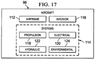
- the aircraft 96 produced by exemplary method 94 may include an airframe 112 with a plurality of systems 114 and an interior 116.
- high-level systems 114 include one or more of a propulsion system 118, an electrical system 120, a hydraulic system 122, and an environmental system 124. Any number of other systems may be included.
- an aerospace example is shown, the principles of the disclosure may be applied to other industries, such as the marine and automotive industries.
- Systems and methods embodied herein may be employed during any one or more of the stages of the production and service method 94.
- components or subassemblies corresponding to production process 102 may be fabricated or manufactured in a manner similar to components or subassemblies produced while the aircraft 96 is in service.
- one or more apparatus embodiments, method embodiments, or a combination thereof may be utilized during the production stages 102 and 104, for example, by substantially expediting assembly of or reducing the cost of an aircraft 96.
- apparatus embodiments, method embodiments, or a combination thereof may be utilized while the aircraft 96 is in service, for example and without limitation, to maintenance and service 110.
Landscapes
- Engineering & Computer Science (AREA)
- Mechanical Engineering (AREA)
- Health & Medical Sciences (AREA)
- Thermal Sciences (AREA)
- Oral & Maxillofacial Surgery (AREA)
- Physics & Mathematics (AREA)
- Chemical & Material Sciences (AREA)
- Composite Materials (AREA)
- Manufacturing & Machinery (AREA)
- Casting Or Compression Moulding Of Plastics Or The Like (AREA)
- Moulds For Moulding Plastics Or The Like (AREA)
- Moulding By Coating Moulds (AREA)
- Heating, Cooling, Or Curing Plastics Or The Like In General (AREA)
Applications Claiming Priority (1)
| Application Number | Priority Date | Filing Date | Title |
|---|---|---|---|
| US13/491,698 US9381704B2 (en) | 2012-06-08 | 2012-06-08 | Non-vented bladder system for curing composite parts |
Publications (2)
| Publication Number | Publication Date |
|---|---|
| EP2671709A1 EP2671709A1 (en) | 2013-12-11 |
| EP2671709B1 true EP2671709B1 (en) | 2016-02-03 |
Family
ID=48468178
Family Applications (1)
| Application Number | Title | Priority Date | Filing Date |
|---|---|---|---|
| EP13169023.2A Active EP2671709B1 (en) | 2012-06-08 | 2013-05-23 | Non-vented bladder system for curing composite parts |
Country Status (9)
| Country | Link |
|---|---|
| US (2) | US9381704B2 (enExample) |
| EP (1) | EP2671709B1 (enExample) |
| JP (1) | JP6170346B2 (enExample) |
| KR (1) | KR102052923B1 (enExample) |
| CN (1) | CN103481433B (enExample) |
| BR (1) | BR102013014257B1 (enExample) |
| CA (1) | CA2812376C (enExample) |
| ES (1) | ES2564140T3 (enExample) |
| RU (1) | RU2660136C9 (enExample) |
Families Citing this family (17)
| Publication number | Priority date | Publication date | Assignee | Title |
|---|---|---|---|---|
| US9381704B2 (en) | 2012-06-08 | 2016-07-05 | The Boeing Company | Non-vented bladder system for curing composite parts |
| US9399509B2 (en) * | 2014-04-10 | 2016-07-26 | The Boeing Company | Vent stringer fitting |
| US9914244B2 (en) * | 2014-08-04 | 2018-03-13 | The Boeing Company | Bladder system for curing composite parts |
| US9399510B2 (en) * | 2014-08-20 | 2016-07-26 | The Boeing Company | Hat stringer closeout fitting and method of making same |
| US10144185B2 (en) * | 2015-04-01 | 2018-12-04 | The Boeing Company | Method and apparatus for high-temperature post-curing of UV-cured photopolymers |
| US10315366B2 (en) | 2015-05-11 | 2019-06-11 | Gulfstream Aerospace Corporation | Apparatuses and methods for making reinforcement structures |
| US10843416B2 (en) | 2015-05-11 | 2020-11-24 | Gulfstream Aerospace Corporation | Composite reinforcement structures and aircraft assemblies comprising composite reinforcement structures |
| US20160339682A1 (en) * | 2015-05-18 | 2016-11-24 | The Boeing Company | Bladder System for Curing Composite Parts |
| US10293552B2 (en) | 2015-11-17 | 2019-05-21 | The Boeing Company | Heat shrinkable film tube and method for manufacturing hollow composite parts |
| US10639855B2 (en) * | 2017-02-07 | 2020-05-05 | General Electric Company | Applicator systems for applying pressure to a structure |
| US10751955B2 (en) | 2017-04-10 | 2020-08-25 | The Boeing Company | Unitized composite structure manufacturing system |
| US10710319B2 (en) | 2017-08-02 | 2020-07-14 | The Boeing Company | Controlling application of forces to different portions of object surface using bladder |
| US10710320B2 (en) | 2017-08-02 | 2020-07-14 | The Boeing Company | Controlling application of forces to different portions of object surface using flexible wall |
| EP3587063B1 (en) | 2017-09-07 | 2022-03-09 | Kawasaki Jukogyo Kabushiki Kaisha | Mold for manufacturing composite material molded products, and method for manufacturing composite material molded products |
| CN108162433B (zh) * | 2018-03-01 | 2020-04-10 | 江苏金风科技有限公司 | 真空灌注辅助装置及真空灌注工艺 |
| GB2575102A (en) * | 2018-06-29 | 2020-01-01 | Airbus Operations Ltd | Duct stringer with bulkhead |
| IT202000018136A1 (it) * | 2020-07-27 | 2022-01-27 | Leonardo Spa | Procedimento per la fabbricazione di un componente strutturale in materiale composito irrigidito con almeno un corrente |
Family Cites Families (19)
| Publication number | Priority date | Publication date | Assignee | Title |
|---|---|---|---|---|
| US4178406A (en) * | 1977-12-29 | 1979-12-11 | Rohm And Haas Company | Three-layered fiberglass construction |
| US4222721A (en) * | 1978-09-08 | 1980-09-16 | The Firestone Tire & Rubber Company | Apparatus for curing tires and the like |
| US5484277A (en) | 1989-12-26 | 1996-01-16 | Mcdonnell Douglas Corporation | Mandreless molding system |
| SU1785910A1 (ru) * | 1990-02-19 | 1993-01-07 | B Yuzhn K | Способ изготовления слоистой конструкции из композиционного материала и устройство для его осуществления |
| US5366684A (en) * | 1992-12-31 | 1994-11-22 | Grumman Aerospace Corporation | Molding composite method using an inflatable bladder pressurized in an autoclave |
| ES2523071T3 (es) * | 2001-01-25 | 2014-11-20 | Quickstep Technologies Pty, Ltd | Sistema y método para la producción de un componente de material compuesto o de metal enlazado |
| JP2005527410A (ja) * | 2002-05-29 | 2005-09-15 | ザ・ボーイング・カンパニー | 制御された大気圧樹脂注入プロセス |
| US7335012B2 (en) * | 2004-12-22 | 2008-02-26 | General Electric Company | Apparatus for fabricating reinforced composite materials |
| US8834782B2 (en) | 2007-08-07 | 2014-09-16 | William L. Rodman | Composite structures and methods of making same |
| US9238335B2 (en) | 2008-07-10 | 2016-01-19 | The Boeing Company | Mandrel for autoclave curing applications |
| US9327467B2 (en) | 2008-07-10 | 2016-05-03 | The Boeing Company | Composite mandrel for autoclave curing applications |
| US8652371B2 (en) * | 2008-11-20 | 2014-02-18 | Cytec Technology Corp. | Constant pressure infusion process for resin transfer molding |
| JP5313646B2 (ja) * | 2008-12-04 | 2013-10-09 | 株式会社ニューケミカル | 繊維強化樹脂成形品の製造方法 |
| US8293051B2 (en) | 2008-12-10 | 2012-10-23 | The Boeing Company | Method for producing composite laminates using a collapsible mandrel |
| US20100186899A1 (en) * | 2009-01-15 | 2010-07-29 | Airtech International, Inc. | Thermoplastic mandrels for composite fabrication |
| US8074694B2 (en) | 2009-05-28 | 2011-12-13 | The Boeing Company | Stringer transition method |
| JP5430424B2 (ja) * | 2010-01-28 | 2014-02-26 | 本田技研工業株式会社 | 航空機翼構造の成形方法 |
| US8430984B2 (en) * | 2010-05-11 | 2013-04-30 | The Boeing Company | Collapsible mandrel employing reinforced fluoroelastomeric bladder |
| US9381704B2 (en) | 2012-06-08 | 2016-07-05 | The Boeing Company | Non-vented bladder system for curing composite parts |
-
2012
- 2012-06-08 US US13/491,698 patent/US9381704B2/en active Active
-
2013
- 2013-04-09 CA CA2812376A patent/CA2812376C/en active Active
- 2013-04-18 KR KR1020130042634A patent/KR102052923B1/ko active Active
- 2013-05-23 ES ES13169023.2T patent/ES2564140T3/es active Active
- 2013-05-23 EP EP13169023.2A patent/EP2671709B1/en active Active
- 2013-06-04 RU RU2013125720A patent/RU2660136C9/ru active
- 2013-06-05 JP JP2013119019A patent/JP6170346B2/ja active Active
- 2013-06-07 CN CN201310224985.1A patent/CN103481433B/zh active Active
- 2013-06-07 BR BR102013014257-3A patent/BR102013014257B1/pt active IP Right Grant
-
2016
- 2016-07-01 US US15/200,330 patent/US10040256B2/en active Active
Also Published As
| Publication number | Publication date |
|---|---|
| KR102052923B1 (ko) | 2019-12-11 |
| CN103481433B (zh) | 2017-03-01 |
| JP2014012399A (ja) | 2014-01-23 |
| US20130327477A1 (en) | 2013-12-12 |
| BR102013014257B1 (pt) | 2020-12-01 |
| KR20130138099A (ko) | 2013-12-18 |
| CA2812376C (en) | 2015-06-23 |
| JP6170346B2 (ja) | 2017-07-26 |
| RU2660136C2 (ru) | 2018-07-05 |
| US20160311179A1 (en) | 2016-10-27 |
| CN103481433A (zh) | 2014-01-01 |
| ES2564140T3 (es) | 2016-03-18 |
| BR102013014257A2 (pt) | 2015-06-23 |
| CA2812376A1 (en) | 2013-12-08 |
| RU2013125720A (ru) | 2014-12-10 |
| US9381704B2 (en) | 2016-07-05 |
| RU2660136C9 (ru) | 2018-11-29 |
| EP2671709A1 (en) | 2013-12-11 |
| US10040256B2 (en) | 2018-08-07 |
Similar Documents
| Publication | Publication Date | Title |
|---|---|---|
| EP2671709B1 (en) | Non-vented bladder system for curing composite parts | |
| US8613301B2 (en) | Compaction of prepreg plies on composite laminate structures | |
| US8601694B2 (en) | Method for forming and installing stringers | |
| EP2903806B1 (en) | Method and apparatus for co-curing composite skins and stiffeners in an autoclave | |
| US12220884B2 (en) | Methods and devices for supporting of variety of different pre-cured composite stringers | |
| EP2982496B1 (en) | Bladder system for curing composite parts | |
| EP3815888B1 (en) | Vacuum bag-less composite repair systems and repairs | |
| EP4074498B1 (en) | Apparatus and method for processing a composite structure | |
| US11034431B2 (en) | Composite article with fly-away bag carrier | |
| US20220152956A1 (en) | Caul Plate System for Aircraft Fabrication | |
| EP4477378A1 (en) | Vacuum bag sealing system | |
| EP4491382B1 (en) | Curing tool assemblies, methods and systems for composite manufacturing | |
| EP4480684A1 (en) | Reusable composite curing system | |
| US12434450B2 (en) | Bladder vent plugs for composite manufacturing and related methods and systems | |
| EP4011606B1 (en) | Caul plate system for aircraft fabrication |
Legal Events
| Date | Code | Title | Description |
|---|---|---|---|
| PUAI | Public reference made under article 153(3) epc to a published international application that has entered the european phase |
Free format text: ORIGINAL CODE: 0009012 |
|
| 17P | Request for examination filed |
Effective date: 20130523 |
|
| AK | Designated contracting states |
Kind code of ref document: A1 Designated state(s): AL AT BE BG CH CY CZ DE DK EE ES FI FR GB GR HR HU IE IS IT LI LT LU LV MC MK MT NL NO PL PT RO RS SE SI SK SM TR |
|
| AX | Request for extension of the european patent |
Extension state: BA ME |
|
| 17Q | First examination report despatched |
Effective date: 20140805 |
|
| GRAP | Despatch of communication of intention to grant a patent |
Free format text: ORIGINAL CODE: EPIDOSNIGR1 |
|
| RIC1 | Information provided on ipc code assigned before grant |
Ipc: B29C 33/10 20060101ALI20150722BHEP Ipc: B29C 33/40 20060101ALI20150722BHEP Ipc: B29C 43/36 20060101ALN20150722BHEP Ipc: B29C 70/44 20060101AFI20150722BHEP Ipc: B29C 33/48 20060101ALI20150722BHEP Ipc: B29C 33/50 20060101ALI20150722BHEP |
|
| INTG | Intention to grant announced |
Effective date: 20150806 |
|
| GRAS | Grant fee paid |
Free format text: ORIGINAL CODE: EPIDOSNIGR3 |
|
| GRAA | (expected) grant |
Free format text: ORIGINAL CODE: 0009210 |
|
| AK | Designated contracting states |
Kind code of ref document: B1 Designated state(s): AL AT BE BG CH CY CZ DE DK EE ES FI FR GB GR HR HU IE IS IT LI LT LU LV MC MK MT NL NO PL PT RO RS SE SI SK SM TR |
|
| REG | Reference to a national code |
Ref country code: GB Ref legal event code: FG4D |
|
| REG | Reference to a national code |
Ref country code: AT Ref legal event code: REF Ref document number: 773449 Country of ref document: AT Kind code of ref document: T Effective date: 20160215 Ref country code: CH Ref legal event code: EP |
|
| REG | Reference to a national code |
Ref country code: IE Ref legal event code: FG4D |
|
| REG | Reference to a national code |
Ref country code: ES Ref legal event code: FG2A Ref document number: 2564140 Country of ref document: ES Kind code of ref document: T3 Effective date: 20160318 |
|
| REG | Reference to a national code |
Ref country code: DE Ref legal event code: R096 Ref document number: 602013004854 Country of ref document: DE |
|
| REG | Reference to a national code |
Ref country code: PT Ref legal event code: SC4A Free format text: AVAILABILITY OF NATIONAL TRANSLATION Effective date: 20160307 |
|
| REG | Reference to a national code |
Ref country code: SE Ref legal event code: TRGR |
|
| REG | Reference to a national code |
Ref country code: FR Ref legal event code: PLFP Year of fee payment: 4 |
|
| REG | Reference to a national code |
Ref country code: LT Ref legal event code: MG4D Ref country code: NL Ref legal event code: MP Effective date: 20160203 |
|
| REG | Reference to a national code |
Ref country code: AT Ref legal event code: MK05 Ref document number: 773449 Country of ref document: AT Kind code of ref document: T Effective date: 20160203 |
|
| PG25 | Lapsed in a contracting state [announced via postgrant information from national office to epo] |
Ref country code: FI Free format text: LAPSE BECAUSE OF FAILURE TO SUBMIT A TRANSLATION OF THE DESCRIPTION OR TO PAY THE FEE WITHIN THE PRESCRIBED TIME-LIMIT Effective date: 20160203 Ref country code: GR Free format text: LAPSE BECAUSE OF FAILURE TO SUBMIT A TRANSLATION OF THE DESCRIPTION OR TO PAY THE FEE WITHIN THE PRESCRIBED TIME-LIMIT Effective date: 20160504 Ref country code: HR Free format text: LAPSE BECAUSE OF FAILURE TO SUBMIT A TRANSLATION OF THE DESCRIPTION OR TO PAY THE FEE WITHIN THE PRESCRIBED TIME-LIMIT Effective date: 20160203 Ref country code: NO Free format text: LAPSE BECAUSE OF FAILURE TO SUBMIT A TRANSLATION OF THE DESCRIPTION OR TO PAY THE FEE WITHIN THE PRESCRIBED TIME-LIMIT Effective date: 20160503 |
|
| PG25 | Lapsed in a contracting state [announced via postgrant information from national office to epo] |
Ref country code: NL Free format text: LAPSE BECAUSE OF FAILURE TO SUBMIT A TRANSLATION OF THE DESCRIPTION OR TO PAY THE FEE WITHIN THE PRESCRIBED TIME-LIMIT Effective date: 20160203 Ref country code: PL Free format text: LAPSE BECAUSE OF FAILURE TO SUBMIT A TRANSLATION OF THE DESCRIPTION OR TO PAY THE FEE WITHIN THE PRESCRIBED TIME-LIMIT Effective date: 20160203 Ref country code: BE Free format text: LAPSE BECAUSE OF NON-PAYMENT OF DUE FEES Effective date: 20160531 Ref country code: IS Free format text: LAPSE BECAUSE OF FAILURE TO SUBMIT A TRANSLATION OF THE DESCRIPTION OR TO PAY THE FEE WITHIN THE PRESCRIBED TIME-LIMIT Effective date: 20160603 Ref country code: RS Free format text: LAPSE BECAUSE OF FAILURE TO SUBMIT A TRANSLATION OF THE DESCRIPTION OR TO PAY THE FEE WITHIN THE PRESCRIBED TIME-LIMIT Effective date: 20160203 Ref country code: AT Free format text: LAPSE BECAUSE OF FAILURE TO SUBMIT A TRANSLATION OF THE DESCRIPTION OR TO PAY THE FEE WITHIN THE PRESCRIBED TIME-LIMIT Effective date: 20160203 Ref country code: LV Free format text: LAPSE BECAUSE OF FAILURE TO SUBMIT A TRANSLATION OF THE DESCRIPTION OR TO PAY THE FEE WITHIN THE PRESCRIBED TIME-LIMIT Effective date: 20160203 Ref country code: LT Free format text: LAPSE BECAUSE OF FAILURE TO SUBMIT A TRANSLATION OF THE DESCRIPTION OR TO PAY THE FEE WITHIN THE PRESCRIBED TIME-LIMIT Effective date: 20160203 |
|
| PG25 | Lapsed in a contracting state [announced via postgrant information from national office to epo] |
Ref country code: EE Free format text: LAPSE BECAUSE OF FAILURE TO SUBMIT A TRANSLATION OF THE DESCRIPTION OR TO PAY THE FEE WITHIN THE PRESCRIBED TIME-LIMIT Effective date: 20160203 Ref country code: DK Free format text: LAPSE BECAUSE OF FAILURE TO SUBMIT A TRANSLATION OF THE DESCRIPTION OR TO PAY THE FEE WITHIN THE PRESCRIBED TIME-LIMIT Effective date: 20160203 |
|
| REG | Reference to a national code |
Ref country code: DE Ref legal event code: R097 Ref document number: 602013004854 Country of ref document: DE |
|
| PG25 | Lapsed in a contracting state [announced via postgrant information from national office to epo] |
Ref country code: SK Free format text: LAPSE BECAUSE OF FAILURE TO SUBMIT A TRANSLATION OF THE DESCRIPTION OR TO PAY THE FEE WITHIN THE PRESCRIBED TIME-LIMIT Effective date: 20160203 Ref country code: CZ Free format text: LAPSE BECAUSE OF FAILURE TO SUBMIT A TRANSLATION OF THE DESCRIPTION OR TO PAY THE FEE WITHIN THE PRESCRIBED TIME-LIMIT Effective date: 20160203 Ref country code: SM Free format text: LAPSE BECAUSE OF FAILURE TO SUBMIT A TRANSLATION OF THE DESCRIPTION OR TO PAY THE FEE WITHIN THE PRESCRIBED TIME-LIMIT Effective date: 20160203 Ref country code: RO Free format text: LAPSE BECAUSE OF FAILURE TO SUBMIT A TRANSLATION OF THE DESCRIPTION OR TO PAY THE FEE WITHIN THE PRESCRIBED TIME-LIMIT Effective date: 20160203 |
|
| PLBE | No opposition filed within time limit |
Free format text: ORIGINAL CODE: 0009261 |
|
| STAA | Information on the status of an ep patent application or granted ep patent |
Free format text: STATUS: NO OPPOSITION FILED WITHIN TIME LIMIT |
|
| PG25 | Lapsed in a contracting state [announced via postgrant information from national office to epo] |
Ref country code: BE Free format text: LAPSE BECAUSE OF FAILURE TO SUBMIT A TRANSLATION OF THE DESCRIPTION OR TO PAY THE FEE WITHIN THE PRESCRIBED TIME-LIMIT Effective date: 20160203 Ref country code: LU Free format text: LAPSE BECAUSE OF FAILURE TO SUBMIT A TRANSLATION OF THE DESCRIPTION OR TO PAY THE FEE WITHIN THE PRESCRIBED TIME-LIMIT Effective date: 20160523 |
|
| REG | Reference to a national code |
Ref country code: CH Ref legal event code: PL |
|
| 26N | No opposition filed |
Effective date: 20161104 |
|
| PG25 | Lapsed in a contracting state [announced via postgrant information from national office to epo] |
Ref country code: LI Free format text: LAPSE BECAUSE OF NON-PAYMENT OF DUE FEES Effective date: 20160531 Ref country code: CH Free format text: LAPSE BECAUSE OF NON-PAYMENT OF DUE FEES Effective date: 20160531 |
|
| REG | Reference to a national code |
Ref country code: IE Ref legal event code: MM4A |
|
| PG25 | Lapsed in a contracting state [announced via postgrant information from national office to epo] |
Ref country code: SI Free format text: LAPSE BECAUSE OF FAILURE TO SUBMIT A TRANSLATION OF THE DESCRIPTION OR TO PAY THE FEE WITHIN THE PRESCRIBED TIME-LIMIT Effective date: 20160203 Ref country code: BG Free format text: LAPSE BECAUSE OF FAILURE TO SUBMIT A TRANSLATION OF THE DESCRIPTION OR TO PAY THE FEE WITHIN THE PRESCRIBED TIME-LIMIT Effective date: 20160503 |
|
| REG | Reference to a national code |
Ref country code: FR Ref legal event code: PLFP Year of fee payment: 5 |
|
| PG25 | Lapsed in a contracting state [announced via postgrant information from national office to epo] |
Ref country code: IE Free format text: LAPSE BECAUSE OF NON-PAYMENT OF DUE FEES Effective date: 20160523 |
|
| REG | Reference to a national code |
Ref country code: FR Ref legal event code: PLFP Year of fee payment: 6 |
|
| PG25 | Lapsed in a contracting state [announced via postgrant information from national office to epo] |
Ref country code: CY Free format text: LAPSE BECAUSE OF FAILURE TO SUBMIT A TRANSLATION OF THE DESCRIPTION OR TO PAY THE FEE WITHIN THE PRESCRIBED TIME-LIMIT Effective date: 20160203 Ref country code: HU Free format text: LAPSE BECAUSE OF FAILURE TO SUBMIT A TRANSLATION OF THE DESCRIPTION OR TO PAY THE FEE WITHIN THE PRESCRIBED TIME-LIMIT; INVALID AB INITIO Effective date: 20130523 |
|
| PG25 | Lapsed in a contracting state [announced via postgrant information from national office to epo] |
Ref country code: TR Free format text: LAPSE BECAUSE OF FAILURE TO SUBMIT A TRANSLATION OF THE DESCRIPTION OR TO PAY THE FEE WITHIN THE PRESCRIBED TIME-LIMIT Effective date: 20160203 Ref country code: MC Free format text: LAPSE BECAUSE OF FAILURE TO SUBMIT A TRANSLATION OF THE DESCRIPTION OR TO PAY THE FEE WITHIN THE PRESCRIBED TIME-LIMIT Effective date: 20160203 Ref country code: MK Free format text: LAPSE BECAUSE OF FAILURE TO SUBMIT A TRANSLATION OF THE DESCRIPTION OR TO PAY THE FEE WITHIN THE PRESCRIBED TIME-LIMIT Effective date: 20160203 Ref country code: MT Free format text: LAPSE BECAUSE OF NON-PAYMENT OF DUE FEES Effective date: 20160531 |
|
| PG25 | Lapsed in a contracting state [announced via postgrant information from national office to epo] |
Ref country code: AL Free format text: LAPSE BECAUSE OF FAILURE TO SUBMIT A TRANSLATION OF THE DESCRIPTION OR TO PAY THE FEE WITHIN THE PRESCRIBED TIME-LIMIT Effective date: 20160203 |
|
| REG | Reference to a national code |
Ref country code: DE Ref legal event code: R082 Ref document number: 602013004854 Country of ref document: DE Representative=s name: KILBURN & STRODE LLP, NL |
|
| REG | Reference to a national code |
Ref country code: FR Ref legal event code: PLFP Year of fee payment: 10 |
|
| P01 | Opt-out of the competence of the unified patent court (upc) registered |
Effective date: 20230516 |
|
| PGFP | Annual fee paid to national office [announced via postgrant information from national office to epo] |
Ref country code: DE Payment date: 20250529 Year of fee payment: 13 |
|
| PGFP | Annual fee paid to national office [announced via postgrant information from national office to epo] |
Ref country code: ES Payment date: 20250602 Year of fee payment: 13 Ref country code: GB Payment date: 20250527 Year of fee payment: 13 |
|
| PGFP | Annual fee paid to national office [announced via postgrant information from national office to epo] |
Ref country code: IT Payment date: 20250521 Year of fee payment: 13 |
|
| PGFP | Annual fee paid to national office [announced via postgrant information from national office to epo] |
Ref country code: PT Payment date: 20250506 Year of fee payment: 13 |
|
| PGFP | Annual fee paid to national office [announced via postgrant information from national office to epo] |
Ref country code: FR Payment date: 20250526 Year of fee payment: 13 |
|
| PGFP | Annual fee paid to national office [announced via postgrant information from national office to epo] |
Ref country code: SE Payment date: 20250527 Year of fee payment: 13 |