EP2670531B1 - Broyeur à percussion à dispositif de positionnement du rotor - Google Patents
Broyeur à percussion à dispositif de positionnement du rotor Download PDFInfo
- Publication number
- EP2670531B1 EP2670531B1 EP12705364.3A EP12705364A EP2670531B1 EP 2670531 B1 EP2670531 B1 EP 2670531B1 EP 12705364 A EP12705364 A EP 12705364A EP 2670531 B1 EP2670531 B1 EP 2670531B1
- Authority
- EP
- European Patent Office
- Prior art keywords
- rotor
- impact
- strikers
- mill according
- impact mill
- Prior art date
- Legal status (The legal status is an assumption and is not a legal conclusion. Google has not performed a legal analysis and makes no representation as to the accuracy of the status listed.)
- Active
Links
Images
Classifications
-
- B—PERFORMING OPERATIONS; TRANSPORTING
- B02—CRUSHING, PULVERISING, OR DISINTEGRATING; PREPARATORY TREATMENT OF GRAIN FOR MILLING
- B02C—CRUSHING, PULVERISING, OR DISINTEGRATING IN GENERAL; MILLING GRAIN
- B02C13/00—Disintegrating by mills having rotary beater elements ; Hammer mills
- B02C13/02—Disintegrating by mills having rotary beater elements ; Hammer mills with horizontal rotor shaft
- B02C13/06—Disintegrating by mills having rotary beater elements ; Hammer mills with horizontal rotor shaft with beaters rigidly connected to the rotor
- B02C13/09—Disintegrating by mills having rotary beater elements ; Hammer mills with horizontal rotor shaft with beaters rigidly connected to the rotor and throwing the material against an anvil or impact plate
- B02C13/095—Disintegrating by mills having rotary beater elements ; Hammer mills with horizontal rotor shaft with beaters rigidly connected to the rotor and throwing the material against an anvil or impact plate with an adjustable anvil or impact plate
-
- B—PERFORMING OPERATIONS; TRANSPORTING
- B02—CRUSHING, PULVERISING, OR DISINTEGRATING; PREPARATORY TREATMENT OF GRAIN FOR MILLING
- B02C—CRUSHING, PULVERISING, OR DISINTEGRATING IN GENERAL; MILLING GRAIN
- B02C13/00—Disintegrating by mills having rotary beater elements ; Hammer mills
- B02C13/26—Details
-
- B—PERFORMING OPERATIONS; TRANSPORTING
- B02—CRUSHING, PULVERISING, OR DISINTEGRATING; PREPARATORY TREATMENT OF GRAIN FOR MILLING
- B02C—CRUSHING, PULVERISING, OR DISINTEGRATING IN GENERAL; MILLING GRAIN
- B02C13/00—Disintegrating by mills having rotary beater elements ; Hammer mills
- B02C13/26—Details
- B02C13/30—Driving mechanisms
-
- B—PERFORMING OPERATIONS; TRANSPORTING
- B02—CRUSHING, PULVERISING, OR DISINTEGRATING; PREPARATORY TREATMENT OF GRAIN FOR MILLING
- B02C—CRUSHING, PULVERISING, OR DISINTEGRATING IN GENERAL; MILLING GRAIN
- B02C25/00—Control arrangements specially adapted for crushing or disintegrating
Definitions
- the present invention relates to impact mills with a rotor positioning device.
- Impact crushers are generally intended to be installed in quarries or mines for the dimensional reduction of aggregates or ores. They comprise a grinding chamber containing a rotor which is provided with strikers regularly arranged on its periphery, and at least one shock screen which at its upper end is pivotally mounted on a hinge connected to the frame of the grinder.
- the shock screen can be pivoted with a tuning ram to move the bottom end of the screen closer to or away from the rotor to define between the bottom end of the screen and the end. free of one of the strikers, a gap R (see figure 1 ) which determines a given particle size.
- the aggregates are introduced through a feed opening and are struck by the strikers secured to the rotor and sent against the shock shield or screens to see their reduced dimensions. Once introduced, the aggregates undergo this process several times until they reach the size of the adjustment gap R between the lower end of the last shock screen and the end of the strikers. Once this dimension is reached, the reduced granulate passes between the strikers and the screen and is evacuated towards the exit.
- the distance R between the end of the strikers and the edge of the last shock screen, the one which is closest to the rotor, is modified by the wear of the strikers and must therefore be readjusted periodically to keep a regular grain size. It must also be pre-set before each grinding process to be adjusted to the desired output size.
- this adjustment is done manually by the operator, who must first, when stationary, turn the rotor until it has the end of one of the strikers as close as possible. from the bottom end of the last shock screen, then make a manual measurement of the distance between this end of the firing pin and that of the screen. It can then either perform a manual adjustment with screws and nuts, or act on the hydraulic unit controlling the output of the cylinder. positioning the screen until you get the desired distance.
- the patent FR2837407 Applicant proposes means for adjusting the deviation R without direct manual intervention of the operator indexing the position of the rotor for adjustment.
- the percussion mill is provided with a rotor positioning device which comprises a prism-shaped indexing piece, coaxial and fixed in rotation with the rotor and having a number of projecting ridges equal to the number of strikers.
- This indexing piece may abut against an indexing plate mounted at the end of an indexing ram rod to cause rotation of the rotor to a position in which the end of the striker corresponding to the edge is in the maximum approach position with the shock screen.
- the screen is rotated by means of the adjusting cylinder until it reaches the end of the firing pin so as to define the origin of the adjustment of the gap R between these two elements, and subsequently adjust the gap for the desired particle size.
- This last operation is particularly delicate since to change a striker it will rotate the rotor so that the striker to be changed is directed upwards, substantially in a vertical position, to be either out of the top, or slid on the side, after the rotor shaft has been locked in rotation in this position.
- This operation becomes particularly difficult when the striker change is not in the desired substantially vertical position when the end of one of the other strikers is in front of the lower end of the last shock screen. This is, among other things, the case when the number of strikers is 5, 6 or 7.
- the object of the invention is to overcome the disadvantages of known mills with the characteristics of the mill according to the invention.
- the object of the invention is an impact crusher comprising a frame defining a grinding chamber containing a rotor provided with strikers regularly arranged on its periphery, and at least one shock screen which, at its upper end, is pivotally mounted on an articulation connected to the frame of the mill, so as to be pivoted by means of a respective adjustment jack to move the lower end of the shock shield towards or away from the rotor so as to define, between the lower end of the the impact screen and the free end of one of the strikers, a gap which determines a given grain size
- the mill further comprising a rotor positioning device comprising indexing means for positioning the end of the rotor; one of the strikers in a position of maximum approximation with the shock screen in order to adjust said deviation, characterized in that said positioning device comprises a motor-reducer driving a pinion adapted to engage a toothed wheel disposed at one end of the rotor shaft and integral in rotation thereof to rotate the rotor from a state of
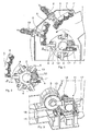
- the impact mill shown in section at the figure 1 comprises a frame defining a grinding chamber 1 in which a rotor 2 is mounted integral with a rotation shaft 3 driven by a motor (not shown).
- the rotor 2 rotates in the illustrated example in the direction indicated by an arrow at the figure 1 .
- It is provided with strikers 4 regularly distributed on its periphery.
- the rotor carries four strikers 4, one of which is hidden behind a mechanism which will be described in detail later.
- shock shields 5 and 6 are arranged in the grinding chamber 1.
- the shock shields 5 and 6 are at their respective high end pivotally mounted on a hinge defined by a respective pivot 7, 8 so as to be able to pivot around that thanks to adjustment cylinders 9 or 10 respectively to bring their free ends closer to or away from the rotor 2.
- the grain size to be obtained for the material to be ground is adjusted by moving the low end of the last lowest screen 5 closer to the rotor periphery, as required, in order to obtain a gap R by which the granulate can pass after reaching the adjustment dimension determined by this deviation.
- the process of adjusting the particle size is carried out as follows.
- the rotor With the machine stationary, the rotor must be rotated until the end of any striker 4 is found opposite the low end of the last lowest screen 5 or the end of the rotor. selected screen, in a setting position.
- a rotor positioning device is provided by means of which the rotor is slowly turned towards this adjustment position to be stopped by means of an indexing device.
- the operator then actuates the adjustment jack 10 to bring the lower end of the lower shock screen 5, the free end of the striker vis-à-vis until they come into contact . He thus determined the origin or the point 0 of the measurement of the deviation R. He then actuates the adjustment jack 10 in the opposite direction until his instrument for measuring the displacement of the jack indicates to him the value corresponding to the desired gap R, that is to say, the given particle size.
- a device for positioning the rotor 2 is associated with the impact mill. It includes indexing means which will be described in more detail later. These means make it possible to position the end of one of the strikers in a position of maximum approximation with the shock screen in order to adjust said deviation.
- this positioning device comprises a geared motor 11 which is preferably a hydraulic geared motor.
- the outgoing shaft (not shown) of this geared motor 11 drives a pinion 12 adapted to engage with a ring gear or gear 13 disposed at one end of the rotor 2 and integral in rotation thereof.
- the pinion 12 is fixed directly on the output shaft of the geared motor 11.
- the geared motor 11 is movable in translation between a first position in which the pinion 12 is released from the socket with the toothed wheel 13 and a second position in engagement therewith.
- the first position is illustrated in Figures 1 to 3 and corresponds to a deactivated position of the geared motor 11 enabling the rotor to be driven by its main rotary drive motor (not shown) for the normal operation of the mill.
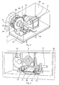
- the second position is illustrated in figure 4 and corresponds to an activated position of the geared motor 11 for driving in rotation at a reduced speed to effect the adjustment of the gap R between the lower end of the shock screen 5 and the free end of one of the strikers or for changing strikers 4.
- the geared motor 11 is fixed on a plate 14 which is itself mounted displaceable in translation on a slideway which in the illustrated example comprises guide rods 15 extending in guide tubes 16 .
- the geared motor 11 is according to another feature of the invention moved in translation with the aid of a control cylinder 17 which is preferably a hydraulic cylinder.
- An adjustable stop 18 with a screw and a stop nut is provided for adjusting the translational travel of the geared motor 11 and the meshing of the gear 12 on the gear wheel 13.
- end-of-travel detectors 19, 20 are advantageously arranged so as to detect the extreme positions of displacement in translation of the geared motor 11 to stop deployment or retraction of the cylinder rod 17 when these extreme positions are reached. .
- the position in which the pinion 12 is engaged with the toothed wheel 13 is maintained by the fact that during this time, the hydraulic pressure is always exerted.
- the pinion 12 can thus come into engagement with the toothed wheel 13 to drive the rotor 2 in rotation from a rest state thereof to the maximum approach position of one of the strikers 4 with respect to the bottom end of the lowest shock screen 5.
- the indexing means comprise a fixed sensor 21 fixed near an end of the shaft 3 of the rotor and able to detect the passage of register members 22 regularly spaced on a ring 23 concentric with the shaft 3 of the rotor 2 and rotatably mounted therewith.
- the number of locating members 22 corresponds to the number of strikers 4.
- the sensor 21 is preferably an induction sensor sensitive to the material of the register members 22.
- the sensor 21 is connected to control means of the geared motor 11 in order to stop its rotation each time a locating member 22 is detected by the sensor 21.
- the gap R between the lower end of the lower screen 5 and the free end of the firing pin 4 which then faces it can then be adjusted as described above.
- the positioning device according to the invention is also intended to be used to position the rotor 2 for the change of the strikers 4 so that one of the strikers 4 is always directed substantially vertically upwards and then removed from above or from the side.
- the angular distance between the strikers is 90 °, which has the consequence that one of the strikers will then be automatically directed substantially vertically upwards when the preceding striker is disposed substantially horizontally with its free end opposite the lower end of the screen 5.
- FIG. figure 2 An example of a rotor 2 carrying 6 strikers 4 is shown in FIG. figure 2 .
- the angular distance between the strikers is 60 °.
- a second fixed sensor 24 is fixed below the first sensor 21 and shifted therefrom 30 ° so that when a striker stops in front of the second sensor 24, one of the strikers will be directed substantially vertically upwards.
- the second sensor 24 may also be disposed above the first sensor 21 and offset by 30 ° thereof to define an angular distance of 60 ° with respect to the next striker which will then be directed substantially vertically to the high.
- the entire assembly comprising the positioning device with the geared motor 11 and the hydraulic cylinder which controls its displacement in translation can advantageously be arranged in a protective casing 25 as is schematically illustrated in FIGS. Figures 4 and 5 .
- a programmable logic controller or any other similar system may also be used to perform all the adjustment sequences automatically after having entered the adjustment of the difference R at the value desired by the operator.
- the impact mill according to the invention may comprise a third shock screen and if it is desired to calibrate a second gap defined between its lower end and the ends of the strikers, simply add a sensor in order to proceed as described for the sensor 21.
- the percussion mill can thus comprise several sensors to ensure adjustments on several shock screens.
Landscapes
- Engineering & Computer Science (AREA)
- Food Science & Technology (AREA)
- Crushing And Grinding (AREA)
- Crushing And Pulverization Processes (AREA)
Description
- La présente invention concerne les broyeurs à percussion à dispositif de positionnement du rotor.
- Les broyeurs à percussion sont généralement destinés à être installés dans les carrières ou mines pour la réduction dimensionnelle de granulats ou de minerais. Ils comportent une chambre de broyage contenant un rotor qui est pourvu de percuteurs régulièrement disposés sur sa périphérie, et au moins un écran de choc qui par son extrémité haute est monté pivotant sur une articulation reliée au bâti du broyeur. L'écran de choc peut pivoter à l'aide d'un vérin de réglage pour rapprocher ou éloigner l'extrémité basse de l'écran par rapport au rotor afin de définir, entre l'extrémité basse de l'écran et l'extrémité libre de l'un des percuteurs, un écart R (voir
figure 1 ) qui détermine une granulométrie donnée. - Dans un broyeur à percussion, les granulats sont introduits par une ouverture d'alimentation puis sont frappés par les percuteurs solidaires du rotor et envoyés contre le ou les écrans de choc pour voir leurs dimensions réduites. Une fois introduits, les granulats subissent ce processus plusieurs fois jusqu'à ce qu'ils atteignent la dimension de l'écart de réglage R entre l'extrémité basse du dernier écran de choc et l'extrémité des percuteurs. Une fois cette dimension atteinte, le granulat réduit passe entre les percuteurs et l'écran et est évacué vers la sortie.
- L'écart R entre l'extrémité des percuteurs et le bord du dernier écran de choc, celui qui est le plus près du rotor, est modifié par l'usure des percuteurs et doit donc être réajusté périodiquement pour garder une granulométrie régulière. Il doit également être préréglé avant chaque processus de broyage pour être ajusté à la granulométrie de sortie recherchée.
- Sur les broyeurs à percussion classiques, ce réglage est effectué manuellement par l'opérateur qui doit tout d'abord, à l'arrêt, virer le rotor jusqu'à ce qu'il présente l'extrémité d'un des percuteurs au plus près de l'extrémité basse du dernier écran de choc, puis procéder à une mesure manuelle de la distance entre cette extrémité du percuteur et celle de l'écran. Il peut alors soit effectuer un réglage manuel par vis et écrous, soit agir sur la centrale hydraulique commandant la sortie du vérin de positionnement de l'écran jusqu'à obtenir la distance désirée.
- Afin de faciliter le réglage de l'écart R entre l'extrémité des percuteurs et le bord du dernier écran de choc, le brevet
FR2837407 - Selon ce brevet, le broyeur de percussion est pourvu d'un dispositif de positionnement du rotor qui comporte une pièce d'indexation en forme de prisme, coaxiale et solidaire en rotation avec le rotor et présentant un nombre d'arêtes en saillie égal au nombre de percuteurs. Cette pièce d'indexation peut venir en appui contre une plaque d'indexation montée à l'extrémité d'une tige de vérin d'indexation afin de provoquer une rotation du rotor jusqu'à une position dans laquelle l'extrémité du percuteur correspondant à l'arête se trouve dans la position de rapprochement maximal avec l'écran de choc.
- Ensuite, l'écran est pivoté au moyen du vérin de réglage jusqu'au contact avec l'extrémité du percuteur de manière à définir l'origine de réglage de l'écart R entre ces deux éléments, et par la suite ajuster l'écart pour la granulométrie recherchée.
- Même si le broyeur selon le brevet
FR2837407 FR2837407 - Cette dernière opération est particulièrement délicate puisque pour changer un percuteur il faudra faire tourner le rotor de sorte que le percuteur à changer se trouve dirigé vers le haut, sensiblement en position verticale, pour être soit sorti par le haut, soit glissé sur le côté, après que l'arbre du rotor a été bloqué en rotation dans cette position. Cette opération devient particulièrement difficile lorsque le percuteur à changer ne se trouve pas dans la position souhaitée sensiblement verticale lorsque l'extrémité d'un des autres percuteurs se trouve en face de l'extrémité basse du dernier écran de choc. Cela est, entre autres, le cas quand le nombre de percuteurs est 5, 6 ou 7.
- Dans ce cas, l'opérateur est obligé d'agir manuellement pour faire tourner le rotor, mais cette manipulation comporte des risques. En effet, notamment pour les broyeurs de dimension importante présentant un arbre de rotor à forte inertie, cette rotation manuelle demande des efforts considérables de la part de l'opérateur.
- Le but de l'invention est de remédier aux inconvénients des broyeurs connus grâce aux caractéristiques du broyeur selon l'invention.
- L'objet de l'invention est un broyeur à percussion comportant un bâti définissant une chambre de broyage contenant un rotor pourvu de percuteurs régulièrement disposés sur sa périphérie, et au moins un écran de choc qui par son extrémité haute est monté pivotant sur une articulation reliée au bâti du broyeur, de manière à pouvoir pivoter à l'aide d'un vérin de réglage respectif pour rapprocher ou éloigner l'extrémité basse de l'écran de choc par rapport au rotor afin de définir, entre l'extrémité basse de l'écran de choc et l'extrémité libre de l'un des percuteurs, un écart qui détermine une granulométrie donnée, le broyeur comportant en outre un dispositif de positionnement du rotor comprenant des moyens d'indexation permettant de positionner l'extrémité d'un des percuteurs dans une position de rapprochement maximal avec l'écran de choc en vue de l'ajustement dudit écart, caractérisé en ce ledit dispositif de positionnement comprend un moto-réducteur entraînant un pignon apte à venir en prise avec une roue dentée disposée à l'une des extrémités de l'arbre du rotor et solidaire en rotation de celui-ci afin d'entraîner en rotation le rotor à partir d'un état de repos jusqu'à ladite position de rapprochement maximal d'un des percuteurs par rapport audit écran de choc.
- Selon d'autres caractéristiques de l'invention :
- le moto-reducteur est monté déplaçable en translation entre une première position dans laquelle ledit pignon est libéré de la prise avec ladite roue dentée et une deuxième position dans laquelle ledit pignon est en prise avec ladite roue dentée;
- le moto-reducteur est déplacé en translation à l'aide d'un vérin;
- une butée est prévue pour arrêter la translation du moto-reducteur lorsque ledit pignon vient en prise avec ladite roue dentée;
- des détecteurs de fin de course sont disposés de manière à détecter les positions extrêmes de déplacement en translation du moto-réducteur;
- lesdits détecteurs sont des interrupteurs de fin de course, ou des capteurs inductifs ;
- le moto-réducteur est fixé sur une plaque déplaçable le long d'une glissière;
- ladite glissière comporte des tiges de guidage;
- lesdits moyens d'indexation comportent des organes de repérage disposés à l'une des extrémités de l'arbre du rotor et détectés par un capteur fixe, le nombre desdits organes de repérage étant égal au nombre de percuteurs;
- ledit capteur est un capteur à induction sensible aux organes de repérage; et
- les moyens d'indexation comportent un deuxième capteur fixe décalé angulairement par rapport au premier capteur afin d'arrêter la rotation du rotor lorsqu'un percuteur se trouve dirigé sensiblement verticalement vers le haut.
- D'autres caractéristiques et avantages de l'invention ressortiront de la description qui va suivre d'un mode de réalisation non limitatif de l'invention, en référence aux figures annexées dans lesquelles :
- la
figure 1 est une vue latérale en coupe d'un broyeur selon l'invention pourvu d'un rotor à quatre percuteurs; - la
figure 2 est une vue latérale en coupe d'un broyeur selon l'invention pourvu d'un rotor à six percuteurs; - la
figure 3 est une vue partielle en perspective illustrant le dispositif de positionnement et d'indexation du rotor dans la position non actionnée de celui-ci; - la
figure 4 est une vue partielle en perspective illustrant le dispositif de positionnement et d'indexation du rotor dans la position actionnée de celui-ci; et - la
figure 5 est une vue latérale illustrant plus en détail le dispositif de positionnement et d'indexation du rotor comprenant un moto-réducteur monté sur une plaque déplaçable en translation. - Dans les figures, les éléments identiques ou équivalents porteront les mêmes signes de référence.
- Le broyeur à percussion représenté en coupe à la
figure 1 comporte un bâti l' définissant une chambre de broyage 1 dans laquelle un rotor 2 est monté solidaire d'un arbre de rotation 3 entraîné par un moteur (non illustré). Le rotor 2 tourne dans l'exemple illustré dans le sens indiqué par une flèche à lafigure 1 . Il est pourvu de percuteurs 4 régulièrement répartis sur sa périphérie. Dans l'exemple représenté à lafigure 1 , le rotor porte quatre percuteurs 4, dont un se trouve caché derrière un mécanisme qui sera décrit en détail plus tard. - Deux écrans de choc 5 et 6 sont disposés dans la chambre de broyage 1. Les écrans de choc 5 et 6 sont à leur extrémité haute respective montés pivotants sur une articulation définie par un pivot respectif 7, 8 de manière à pouvoir pivoter autour de celui-ci grâce à des vérins de réglage 9 respectivement 10 pour rapprocher ou éloigner leurs extrémités libres du rotor 2.
- Le réglage de la granulométrie à obtenir pour le matériau à broyer s'effectue en rapprochant ou en éloignant selon le cas l'extrémité basse du dernier écran le plus bas 5 de la périphérie du rotor afin d'obtenir un écart R grâce auquel le granulat peut passer après avoir atteint la dimension de réglage déterminée par cet écart.
- Le processus de réglage de la granulométrie s'effectue de la façon suivante.
- La machine étant à l'arrêt, il faut faire tourner le rotor jusqu'à ce que l'extrémité d'un percuteur 4 quelconque se retrouve vis-à-vis de l'extrémité basse du dernier écran le plus bas 5 ou de l'écran choisi, dans une position de réglage.
- Dans le
FR2837407 - Egalement dans le broyeur selon l'invention, un dispositif de positionnement du rotor 2 est associé au broyeur à percussion. Il comprend des moyens d'indexation qui seront décrits plus en détail plus tard. Ces moyens permettent de positionner l'extrémité d'un des percuteurs dans une position de rapprochement maximal avec l'écran de choc en vue de l'ajustement dudit écart.
- Selon une caractéristique essentielle de l'invention, ce dispositif de positionnement comprend un moto-réducteur 11 qui de préférence est un moto-réducteur hydraulique. L'arbre sortant (non représenté) de ce moto-réducteur 11 entraîne un pignon 12 apte à venir en prise avec une couronne ou roue dentée 13 disposée à l'une des extrémités du rotor 2 et solidaire en rotation de celui-ci. De préférence, le pignon 12 est fixé directement sur l'arbre sortant du moto-réducteur 11.
- Le moto-réducteur 11 est déplaçable en translation entre une première position dans laquelle le pignon 12 est libéré de la prise avec la roue dentée 13 et une deuxième position en prise avec celle-ci.
- La première position est illustrée aux
figures 1 à 3 et correspond à une position désactivée du moto-réducteur 11 permettant au rotor d'être entraîné par son moteur principal d'entraînement en rotation (non représenté) pour le fonctionnement normal du broyeur. - La deuxième position est illustrée à la
figure 4 et correspond à une position activée du moto-réducteur 11 permettant l'entraînement en rotation à vitesse réduite pour effectuer le réglage de l'écart R entre l'extrémité basse de l'écran de choc 5 et l'extrémité libre d'un des percuteurs ou pour le changement des percuteurs 4. - Pour son déplacement en translation, le moto-réducteur 11 est fixé sur une plaque 14 qui est elle-même montée déplaçable en translation sur une glissière qui dans l'exemple illustré comporte des tiges de guidage 15 s'étendant dans des tubes de guidage 16.
- Le moto-réducteur 11 est selon une autre caractéristique de l'invention déplacé en translation à l'aide d'un vérin de commande 17 qui de préférence est un vérin hydraulique.
- Une butée réglable 18 à vis et écrou d'arrêt est prévue pour régler la course de translation du moto-réducteur 11, et l'engrènement du pignon 12 sur la roue dentée 13.
- En outre, des détecteurs de fin de course 19, 20 sont avantageusement disposés de manière à détecter les positions extrêmes de déplacement en translation du moto-réducteur 11 pour arrêter de déploiement ou la rétraction de la tige du vérin 17 lorsque ces positions extrêmes sont atteintes. La position dans laquelle le pignon 12 est en prise avec la roue dentée 13 est maintenue grâce au fait que pendant ce temps, la pression hydraulique est toujours exercée.
- Par ailleurs, il est avantageux de faire tourner le pignon 12 lorsqu'il est en voie de s'engrener avec la roue dentée 13 de manière à ce qu'il n'y ait pas de point de tangence au moment de l'engrènement entre le pignon et la roue dentée.
- Le pignon 12 peut ainsi venir en prise avec la roue dentée 13 pour entraîner en rotation le rotor 2 à partir d'un état de repos de celui-ci jusqu'à la position de rapprochement maximal d'un des percuteurs 4 par rapport à l'extrémité basse de l'écran de choc le plus bas 5.
- Afin d'arrêter la rotation du rotor 2 précisément dans cette position de rapprochement maximal, les moyens d'indexation selon l'invention comportent un capteur fixe 21 fixé à proximité d'une extrémité de l'arbre 3 du rotor et apte à détecter le passage d'organes de repérage 22 régulièrement espacés sur un anneau 23 concentrique à l'arbre 3 du rotor 2 et monté solidaire en rotation avec celui-ci. Le nombre d'organes de repérage 22 correspond au nombre de percuteurs 4.
- Le capteur 21 est de préférence un capteur à induction sensible au matériau des organes de repérage 22. Le capteur 21 est relié à des moyens de commande du moto-réducteur 11 afin d'arrêter sa rotation à chaque fois qu'un organe de repérage 22 est détecté par le capteur 21.
- L'écart R entre l'extrémité basse de l'écran le plus bas 5 et l'extrémité libre du percuteur 4 qui alors se trouve en face d'elle peut ensuite être réglé de la manière décrite ci-dessus.
- Le dispositif de positionnement selon l'invention est également destiné à être utilisé pour positionner le rotor 2 pour le changement des percuteurs 4 de telle sorte qu'un des percuteurs 4 soit toujours dirigé sensiblement verticalement vers le haut pour ensuite être enlevé par le haut ou par le côté. Dans le cas où le rotor 2 porte quatre percuteurs 4 comme cela est illustré à la
figure 1 , la distance angulaire entre les percuteurs est de 90°, ce qui a pour conséquence qu'un des percuteurs sera alors automatiquement dirigé sensiblement verticalement vers le haut lorsque le percuteur précédent est disposé sensiblement horizontalement avec son extrémité libre en face de l'extrémité basse de l'écran 5. - Il en est autrement si les percuteurs sont au nombre de 5, 6 ou 7. Un exemple d'un rotor 2 portant 6 percuteurs 4 est montré à la
figure 2 . Dans ce cas, la distance angulaire entre les percuteurs est de 60°. Afin de positionner un des percuteurs pour qu'il se trouve dirigé sensiblement verticalement vers le haut pour qu'il puisse être échangé contre un nouveau, un deuxième capteur fixe 24 est fixé en dessous du premier capteur 21 et décalé de celui-ci de 30° de sorte que lorsqu'un percuteur s'arrête en face du deuxième capteur 24, un des percuteurs se trouvera dirigé sensiblement verticalement vers le haut. - Bien entendu, le deuxième capteur 24 peut aussi bien être disposé au-dessus du premier capteur 21 et décalé de 30° de celui-ci pour définir une distance angulaire de 60° par rapport au percuteur suivant qui se trouvera alors dirigé sensiblement verticalement vers le haut.
- Au lieu d'utiliser un deuxième capteur, il serait également possible d'utiliser des moyens de détection de la rotation angulaire de l'arbre 3 du rotor 2 à partir de la position dans laquelle un percuteur s'arrête en face du premier capteur 21 et de faire tourner l'arbre d'une valeur souhaitée pour qu'un autre percuteur soit dirigé sensiblement verticalement vers le haut.
- Tout l'ensemble comprenant le dispositif de positionnement avec le moto-réducteur 11 et le vérin hydraulique qui commande son déplacement en translation peut avantageusement être disposé dans un boîtier de protection 25 comme cela est schématiquement illustré aux
figures 4 et 5 . - Un automate programmable ou tout autre système similaire peut par ailleurs être utilisé pour effectuer automatiquement l'ensemble des séquences de réglage après avoir saisi le réglage de l'écart R à la valeur souhaitée par l'opérateur.
- Bien entendu, l'invention n'est pas limitée aux exemples illustrés et décrits, mais l'homme du métier peut envisager des variantes sans pour autant sortir du cadre de l'invention. Ainsi, le broyeur à percussion selon l'invention peut comporter un troisième écran de choc et si l'on souhaite calibrer un deuxième écart défini entre son extrémité basse et les extrémités des percuteurs, il suffit de rajouter un capteur afin de pouvoir procéder comme décrit pour le capteur 21. Le broyeur à percussion peut ainsi comporter plusieurs capteurs pour assurer des réglages sur plusieurs écrans de choc.
Claims (12)
- Broyeur à percussion comportant un bâti (1') définissant une chambre de broyage (1) contenant un rotor (2) pourvu de percuteurs (4) régulièrement disposés sur sa périphérie, et au moins un écran de choc (5, 6) qui par son extrémité haute est monté pivotant sur une articulation (7, 8) reliée au bâti (1') du broyeur, de manière à pouvoir pivoter à l'aide d'un vérin de réglage respectif (9, 10) pour rapprocher ou éloigner l'extrémité basse de l'écran de choc (5, 6) par rapport au rotor (2) afin de définir, entre l'extrémité basse de l'écran de choc et l'extrémité libre de l'un des percuteurs (4), un écart (R) qui détermine une granulométrie donnée, le broyeur comportant en outre un dispositif de positionnement du rotor (2) comprenant des moyens d'indexation (21, 22) permettant de positionner l'extrémité d'un des percuteurs dans une position de rapprochement maximal avec l'écran de choc (5) en vue de l'ajustement dudit écart, caractérisé en ce ledit dispositif de positionnement comprend un moto-réducteur (11) entraînant un pignon (12) apte à venir en prise avec une roue dentée (13) disposée à l'une des extrémités de l'arbre (3) du rotor (2) et solidaire en rotation de celui-ci afin d'entraîner en rotation le rotor à partir d'un état de repos jusqu'à ladite position de rapprochement maximal d'un des percuteurs (4) par rapport audit écran de choc (5).
- Broyeur à percussion selon la revendication 1, caractérisé en ce que le moto-reducteur (11) est monté déplaçable en translation entre une première position dans laquelle ledit pignon (12) est libéré de la prise avec ladite roue dentée (13) et une deuxième position dans laquelle ledit pignon est en prise avec ladite roue dentée.
- Broyeur à percussion selon la revendication 2, caractérisé en ce que le moto-reducteur (11) est déplacé en translation à l'aide d'un vérin de commande (17).
- Broyeur à percussion selon la revendication 2 ou 3, caractérisé en ce qu'une butée réglable (18) est prévue pour régler la course de translation du moto-reducteur (11) et l'engrènement du pignon (12) sur ladite roue dentée (13).
- Broyeur à percussion selon l'une quelconque des revendications 2 à 4, caractérisé en ce que des détecteurs de fin de course (19, 20) sont disposés de manière à détecter les positions extrêmes de déplacement en translation du moto-réducteur (11).
- Broyeur à percussion selon la revendication 5, caractérisé en ce que lesdits détecteurs (19, 20) sont des interrupteurs de fin de course.
- Broyeur à percussion selon l'une quelconque des revendications 2 à 6, caractérisé en ce que le moto-réducteur (11) est fixé sur une plaque (14) déplaçable le long d'une glissière (15, 16).
- Broyeur à percussion selon la revendication 7, caractérisé en ce que ladite glissière (15, 16) comporte des tiges de guidage (15).
- Broyeur à percussion selon l'une quelconque des revendications précédentes, caractérisé en ce que lesdits moyens d'indexation comportent des organes de repérage (22) disposés à l'une des extrémités de l'arbre du rotor (2) et détectés par un premier capteur fixe (21), le nombre desdits organes de repérage (22) étant égal au nombre de percuteurs (4).
- Broyeur à percussion selon la revendication 9, caractérisé en ce que ledit capteur (21) est un capteur à induction sensible aux organes de repérage (22).
- Broyeur à percussion selon la revendication 9 ou 10, caractérisé en ce que les moyens d'indexation comportent un deuxième capteur fixe (24) décalé angulairement par rapport au premier capteur (21) afin d'arrêter la rotation du rotor (2) lorsqu'un percuteur (4) se trouve dirigé sensiblement verticalement vers le haut.
- Broyeur à percussion selon la revendication 1 caractérisé en ce qu'il comporte plusieurs capteurs pour assurer des réglages sur plusieurs écrans de choc.
Applications Claiming Priority (2)
| Application Number | Priority Date | Filing Date | Title |
|---|---|---|---|
| FR1150701A FR2970882B1 (fr) | 2011-01-31 | 2011-01-31 | Broyeur a percussion a dispositif de positionnement du rotor. |
| PCT/FR2012/050148 WO2012104521A1 (fr) | 2011-01-31 | 2012-01-24 | Broyeur à percussion à dispositif de positionnement du rotor |
Publications (2)
| Publication Number | Publication Date |
|---|---|
| EP2670531A1 EP2670531A1 (fr) | 2013-12-11 |
| EP2670531B1 true EP2670531B1 (fr) | 2015-03-18 |
Family
ID=45755388
Family Applications (1)
| Application Number | Title | Priority Date | Filing Date |
|---|---|---|---|
| EP12705364.3A Active EP2670531B1 (fr) | 2011-01-31 | 2012-01-24 | Broyeur à percussion à dispositif de positionnement du rotor |
Country Status (8)
| Country | Link |
|---|---|
| US (1) | US9289771B2 (fr) |
| EP (1) | EP2670531B1 (fr) |
| CA (1) | CA2819387C (fr) |
| ES (1) | ES2537533T3 (fr) |
| FR (1) | FR2970882B1 (fr) |
| MX (1) | MX352761B (fr) |
| PT (1) | PT2670531E (fr) |
| WO (1) | WO2012104521A1 (fr) |
Families Citing this family (14)
| Publication number | Priority date | Publication date | Assignee | Title |
|---|---|---|---|---|
| FR2998489B1 (fr) | 2012-11-29 | 2014-12-26 | Metso Minerals France Sa | Ecran de choc pour broyeur a percussion, broyeur a percussion pourvu de cet ecran de choc, et installation de broyage |
| EP3023155B1 (fr) | 2014-11-12 | 2017-05-10 | Sandvik Intellectual Property AB | Dispositif pour positionnement de rotor d'un concasseur à impact à arbre horizontal |
| WO2016074712A1 (fr) * | 2014-11-12 | 2016-05-19 | Sandvik Intellectual Property Ab | Dispositif de positionnement de rotor pour concasseur à percussion à arbre horizontal |
| US10596576B2 (en) * | 2015-02-18 | 2020-03-24 | Kolberg-Pioneer, Inc. | Apparatus and method for an apron assembly |
| CN105080654B (zh) * | 2015-08-28 | 2018-11-27 | 长沙深湘通用机器有限公司 | 一种反击式破碎机 |
| CN105080644A (zh) * | 2015-08-28 | 2015-11-25 | 长沙深湘通用机器有限公司 | 一种粗粒粉碎及分选工艺 |
| CN105080653B (zh) * | 2015-08-28 | 2018-11-27 | 长沙深湘通用机器有限公司 | 一种反击式破碎机 |
| CN105597873A (zh) * | 2016-01-27 | 2016-05-25 | 苏州诚亭自动化设备有限公司 | 一种煤块破碎机 |
| WO2018006942A1 (fr) | 2016-07-05 | 2018-01-11 | Sandvik Intellectual Property Ab | Dispositif de positionnement de rotor |
| US10814330B2 (en) | 2016-07-05 | 2020-10-27 | Sandvik Intellectual Property Ab | Rotor locking device |
| CN109201193B (zh) * | 2018-10-15 | 2021-08-31 | 明光市明秀建筑工程有限公司 | 一种道路施工用碎石的偏心凸轴辊压的破碎分选装置 |
| GB2579359B (en) | 2018-11-28 | 2021-04-14 | Terex Gb Ltd | Rotor positioning device of an impact crusher |
| DE102020125132B4 (de) * | 2020-09-25 | 2024-10-31 | Kleemann Gmbh | Verfahren zur Ermittlung des Verschleißes einer Prallschwinge eines Prallbrechers |
| CN115342858B (zh) * | 2022-08-08 | 2025-09-09 | 广东韶钢松山股份有限公司 | 一种送料检测装置以及加热炉系统 |
Family Cites Families (4)
| Publication number | Priority date | Publication date | Assignee | Title |
|---|---|---|---|---|
| US4084752A (en) * | 1975-12-11 | 1978-04-18 | Kawasaki Jukogyo Kabushiki Kaisha | Gap adjusting system for crusher and method |
| FR2837407B1 (fr) | 2002-03-21 | 2004-05-28 | Metso Minerals Macon Sa | Systeme de positionnement du rotor et d'indexation d'un broyeur a percussion |
| AT412451B (de) * | 2003-01-10 | 2005-03-25 | Hermann Dipl Ing Schroedl | Einrichtung und verfahren zur einstellung von brechwerkzeugen |
| FR2893863B1 (fr) * | 2005-11-29 | 2008-06-27 | Krupp Hazemag Soc Par Actions | Machine a percussion pour le concassage et/ou le broyage de matieres minerales. |
-
2011
- 2011-01-31 FR FR1150701A patent/FR2970882B1/fr active Active
-
2012
- 2012-01-24 US US13/977,243 patent/US9289771B2/en active Active
- 2012-01-24 CA CA2819387A patent/CA2819387C/fr active Active
- 2012-01-24 WO PCT/FR2012/050148 patent/WO2012104521A1/fr not_active Ceased
- 2012-01-24 PT PT127053643T patent/PT2670531E/pt unknown
- 2012-01-24 MX MX2013006675A patent/MX352761B/es active IP Right Grant
- 2012-01-24 EP EP12705364.3A patent/EP2670531B1/fr active Active
- 2012-01-24 ES ES12705364.3T patent/ES2537533T3/es active Active
Also Published As
| Publication number | Publication date |
|---|---|
| ES2537533T3 (es) | 2015-06-09 |
| MX352761B (es) | 2017-12-07 |
| EP2670531A1 (fr) | 2013-12-11 |
| US20130284839A1 (en) | 2013-10-31 |
| FR2970882B1 (fr) | 2013-01-18 |
| CA2819387A1 (fr) | 2012-08-09 |
| CA2819387C (fr) | 2019-02-26 |
| MX2013006675A (es) | 2013-11-04 |
| US9289771B2 (en) | 2016-03-22 |
| FR2970882A1 (fr) | 2012-08-03 |
| WO2012104521A1 (fr) | 2012-08-09 |
| PT2670531E (pt) | 2015-06-24 |
Similar Documents
| Publication | Publication Date | Title |
|---|---|---|
| CA2819387C (fr) | Broyeur a percussion a dispositif de positionnement du rotor | |
| CA2423250C (fr) | Systeme de positionnement du rotor et d'indexation d'un broyeur a percussion | |
| CA3075441C (fr) | Deconditionneur a nettoyage ameliore | |
| EP1600730B1 (fr) | Appareil de lecture de contour comportant un palpeur mobile en rotation | |
| EP0285490A1 (fr) | Procédé et appareil pour coller un film protecteur sur une face d'une série de lentilles ophtalmiques | |
| EP0845348B1 (fr) | Guide-fil à frein réglable, recevant des fils projetés sur une surface | |
| FR2929144A1 (fr) | Dispositif de coupe a la volee d'au moins un element filiforme entraine lineairement | |
| WO2014083257A1 (fr) | Ecran de choc pour broyeur a percussion, broyeur a percussion pourvu de cet ecran de choc, et installation de broyage | |
| FR2536002A1 (fr) | ||
| FR2927268A1 (fr) | Broyeur a percussion | |
| EP0022403B1 (fr) | Dispositif indicateur de cote destiné à équiper une machine-outil de formage ou de cisaillage de métaux en feuilles | |
| CH618660A5 (fr) | ||
| EP1964612B1 (fr) | Broyeur à impacts pour le concassage et/ou le broyage de matières minérales comportant des moyens de réglage automatisés | |
| EP0406132A1 (fr) | Procédé et dispositif destiné à découper des tiges végétales pleines en vue de produire des boutures | |
| FR2629448A1 (fr) | Appareillage pour decouper une piece en un materiau du type verre ou ceramique le long d'une ligne incisee | |
| EP0804879B1 (fr) | Machine à grigner | |
| EP0351306A2 (fr) | Broyeur cylindrique comportant des rouleaux intérieurs de broyage | |
| FR2630891A1 (fr) | Egrappoir comprenant un tambour rotatif et un arbre a pales deplacables axialement l'un par rapport a l'autre | |
| EP1048417B1 (fr) | Trancheur pour produits alimentaires tels que saumon fumé, et procédé de tranchage de saumon fumé | |
| FR2719143A1 (fr) | Contrôleur de pièces métalliques, notamment de pièces de monnaie. | |
| FR2549754A1 (fr) | Dispositif de reglage des couteaux coupe-chutes pour cisaille de rives | |
| CH555242A (de) | Machine a serigraphier. | |
| WO1997035798A1 (fr) | Machine de fabrication de matelas de rembourrage a systeme de detection de rotation incorrecte du moteur de coupe | |
| FR2466314A1 (fr) | Machine pour affuter les broches | |
| EP1549818B1 (fr) | Dispositif de commande de store motorise |
Legal Events
| Date | Code | Title | Description |
|---|---|---|---|
| PUAI | Public reference made under article 153(3) epc to a published international application that has entered the european phase |
Free format text: ORIGINAL CODE: 0009012 |
|
| 17P | Request for examination filed |
Effective date: 20130607 |
|
| AK | Designated contracting states |
Kind code of ref document: A1 Designated state(s): AL AT BE BG CH CY CZ DE DK EE ES FI FR GB GR HR HU IE IS IT LI LT LU LV MC MK MT NL NO PL PT RO RS SE SI SK SM TR |
|
| DAX | Request for extension of the european patent (deleted) | ||
| GRAP | Despatch of communication of intention to grant a patent |
Free format text: ORIGINAL CODE: EPIDOSNIGR1 |
|
| INTG | Intention to grant announced |
Effective date: 20141211 |
|
| GRAS | Grant fee paid |
Free format text: ORIGINAL CODE: EPIDOSNIGR3 |
|
| GRAA | (expected) grant |
Free format text: ORIGINAL CODE: 0009210 |
|
| AK | Designated contracting states |
Kind code of ref document: B1 Designated state(s): AL AT BE BG CH CY CZ DE DK EE ES FI FR GB GR HR HU IE IS IT LI LT LU LV MC MK MT NL NO PL PT RO RS SE SI SK SM TR |
|
| REG | Reference to a national code |
Ref country code: GB Ref legal event code: FG4D Free format text: NOT ENGLISH |
|
| RIN1 | Information on inventor provided before grant (corrected) |
Inventor name: FAURE, THIERRY |
|
| REG | Reference to a national code |
Ref country code: CH Ref legal event code: EP |
|
| REG | Reference to a national code |
Ref country code: IE Ref legal event code: FG4D Free format text: LANGUAGE OF EP DOCUMENT: FRENCH |
|
| REG | Reference to a national code |
Ref country code: AT Ref legal event code: REF Ref document number: 716196 Country of ref document: AT Kind code of ref document: T Effective date: 20150415 |
|
| REG | Reference to a national code |
Ref country code: DE Ref legal event code: R096 Ref document number: 602012005990 Country of ref document: DE Effective date: 20150430 |
|
| REG | Reference to a national code |
Ref country code: ES Ref legal event code: FG2A Ref document number: 2537533 Country of ref document: ES Kind code of ref document: T3 Effective date: 20150609 |
|
| REG | Reference to a national code |
Ref country code: PT Ref legal event code: SC4A Free format text: AVAILABILITY OF NATIONAL TRANSLATION Effective date: 20150521 |
|
| REG | Reference to a national code |
Ref country code: SE Ref legal event code: TRGR |
|
| REG | Reference to a national code |
Ref country code: NL Ref legal event code: VDEP Effective date: 20150318 |
|
| REG | Reference to a national code |
Ref country code: NL Ref legal event code: VDEP Effective date: 20150318 |
|
| PG25 | Lapsed in a contracting state [announced via postgrant information from national office to epo] |
Ref country code: HR Free format text: LAPSE BECAUSE OF FAILURE TO SUBMIT A TRANSLATION OF THE DESCRIPTION OR TO PAY THE FEE WITHIN THE PRESCRIBED TIME-LIMIT Effective date: 20150318 Ref country code: LT Free format text: LAPSE BECAUSE OF FAILURE TO SUBMIT A TRANSLATION OF THE DESCRIPTION OR TO PAY THE FEE WITHIN THE PRESCRIBED TIME-LIMIT Effective date: 20150318 Ref country code: NO Free format text: LAPSE BECAUSE OF FAILURE TO SUBMIT A TRANSLATION OF THE DESCRIPTION OR TO PAY THE FEE WITHIN THE PRESCRIBED TIME-LIMIT Effective date: 20150618 Ref country code: FI Free format text: LAPSE BECAUSE OF FAILURE TO SUBMIT A TRANSLATION OF THE DESCRIPTION OR TO PAY THE FEE WITHIN THE PRESCRIBED TIME-LIMIT Effective date: 20150318 |
|
| REG | Reference to a national code |
Ref country code: LT Ref legal event code: MG4D |
|
| PG25 | Lapsed in a contracting state [announced via postgrant information from national office to epo] |
Ref country code: RS Free format text: LAPSE BECAUSE OF FAILURE TO SUBMIT A TRANSLATION OF THE DESCRIPTION OR TO PAY THE FEE WITHIN THE PRESCRIBED TIME-LIMIT Effective date: 20150318 Ref country code: GR Free format text: LAPSE BECAUSE OF FAILURE TO SUBMIT A TRANSLATION OF THE DESCRIPTION OR TO PAY THE FEE WITHIN THE PRESCRIBED TIME-LIMIT Effective date: 20150619 Ref country code: LV Free format text: LAPSE BECAUSE OF FAILURE TO SUBMIT A TRANSLATION OF THE DESCRIPTION OR TO PAY THE FEE WITHIN THE PRESCRIBED TIME-LIMIT Effective date: 20150318 |
|
| PG25 | Lapsed in a contracting state [announced via postgrant information from national office to epo] |
Ref country code: NL Free format text: LAPSE BECAUSE OF FAILURE TO SUBMIT A TRANSLATION OF THE DESCRIPTION OR TO PAY THE FEE WITHIN THE PRESCRIBED TIME-LIMIT Effective date: 20150318 |
|
| PG25 | Lapsed in a contracting state [announced via postgrant information from national office to epo] |
Ref country code: EE Free format text: LAPSE BECAUSE OF FAILURE TO SUBMIT A TRANSLATION OF THE DESCRIPTION OR TO PAY THE FEE WITHIN THE PRESCRIBED TIME-LIMIT Effective date: 20150318 Ref country code: SK Free format text: LAPSE BECAUSE OF FAILURE TO SUBMIT A TRANSLATION OF THE DESCRIPTION OR TO PAY THE FEE WITHIN THE PRESCRIBED TIME-LIMIT Effective date: 20150318 Ref country code: CZ Free format text: LAPSE BECAUSE OF FAILURE TO SUBMIT A TRANSLATION OF THE DESCRIPTION OR TO PAY THE FEE WITHIN THE PRESCRIBED TIME-LIMIT Effective date: 20150318 Ref country code: RO Free format text: LAPSE BECAUSE OF FAILURE TO SUBMIT A TRANSLATION OF THE DESCRIPTION OR TO PAY THE FEE WITHIN THE PRESCRIBED TIME-LIMIT Effective date: 20150318 |
|
| PG25 | Lapsed in a contracting state [announced via postgrant information from national office to epo] |
Ref country code: PL Free format text: LAPSE BECAUSE OF FAILURE TO SUBMIT A TRANSLATION OF THE DESCRIPTION OR TO PAY THE FEE WITHIN THE PRESCRIBED TIME-LIMIT Effective date: 20150318 Ref country code: IS Free format text: LAPSE BECAUSE OF FAILURE TO SUBMIT A TRANSLATION OF THE DESCRIPTION OR TO PAY THE FEE WITHIN THE PRESCRIBED TIME-LIMIT Effective date: 20150718 |
|
| REG | Reference to a national code |
Ref country code: DE Ref legal event code: R097 Ref document number: 602012005990 Country of ref document: DE |
|
| REG | Reference to a national code |
Ref country code: FR Ref legal event code: PLFP Year of fee payment: 5 |
|
| PLBE | No opposition filed within time limit |
Free format text: ORIGINAL CODE: 0009261 |
|
| STAA | Information on the status of an ep patent application or granted ep patent |
Free format text: STATUS: NO OPPOSITION FILED WITHIN TIME LIMIT |
|
| PG25 | Lapsed in a contracting state [announced via postgrant information from national office to epo] |
Ref country code: DK Free format text: LAPSE BECAUSE OF FAILURE TO SUBMIT A TRANSLATION OF THE DESCRIPTION OR TO PAY THE FEE WITHIN THE PRESCRIBED TIME-LIMIT Effective date: 20150318 |
|
| 26N | No opposition filed |
Effective date: 20151221 |
|
| PG25 | Lapsed in a contracting state [announced via postgrant information from national office to epo] |
Ref country code: SI Free format text: LAPSE BECAUSE OF FAILURE TO SUBMIT A TRANSLATION OF THE DESCRIPTION OR TO PAY THE FEE WITHIN THE PRESCRIBED TIME-LIMIT Effective date: 20150318 |
|
| PG25 | Lapsed in a contracting state [announced via postgrant information from national office to epo] |
Ref country code: BE Free format text: LAPSE BECAUSE OF NON-PAYMENT OF DUE FEES Effective date: 20160131 |
|
| PG25 | Lapsed in a contracting state [announced via postgrant information from national office to epo] |
Ref country code: LU Free format text: LAPSE BECAUSE OF FAILURE TO SUBMIT A TRANSLATION OF THE DESCRIPTION OR TO PAY THE FEE WITHIN THE PRESCRIBED TIME-LIMIT Effective date: 20160124 |
|
| REG | Reference to a national code |
Ref country code: CH Ref legal event code: PL |
|
| PG25 | Lapsed in a contracting state [announced via postgrant information from national office to epo] |
Ref country code: MC Free format text: LAPSE BECAUSE OF FAILURE TO SUBMIT A TRANSLATION OF THE DESCRIPTION OR TO PAY THE FEE WITHIN THE PRESCRIBED TIME-LIMIT Effective date: 20150318 |
|
| REG | Reference to a national code |
Ref country code: AT Ref legal event code: UEP Ref document number: 716196 Country of ref document: AT Kind code of ref document: T Effective date: 20150318 |
|
| PG25 | Lapsed in a contracting state [announced via postgrant information from national office to epo] |
Ref country code: CH Free format text: LAPSE BECAUSE OF NON-PAYMENT OF DUE FEES Effective date: 20160131 Ref country code: LI Free format text: LAPSE BECAUSE OF NON-PAYMENT OF DUE FEES Effective date: 20160131 |
|
| REG | Reference to a national code |
Ref country code: IE Ref legal event code: MM4A |
|
| REG | Reference to a national code |
Ref country code: FR Ref legal event code: PLFP Year of fee payment: 6 |
|
| PG25 | Lapsed in a contracting state [announced via postgrant information from national office to epo] |
Ref country code: IE Free format text: LAPSE BECAUSE OF NON-PAYMENT OF DUE FEES Effective date: 20160124 |
|
| PG25 | Lapsed in a contracting state [announced via postgrant information from national office to epo] |
Ref country code: MT Free format text: LAPSE BECAUSE OF FAILURE TO SUBMIT A TRANSLATION OF THE DESCRIPTION OR TO PAY THE FEE WITHIN THE PRESCRIBED TIME-LIMIT Effective date: 20150318 |
|
| REG | Reference to a national code |
Ref country code: FR Ref legal event code: PLFP Year of fee payment: 7 |
|
| PG25 | Lapsed in a contracting state [announced via postgrant information from national office to epo] |
Ref country code: SM Free format text: LAPSE BECAUSE OF FAILURE TO SUBMIT A TRANSLATION OF THE DESCRIPTION OR TO PAY THE FEE WITHIN THE PRESCRIBED TIME-LIMIT Effective date: 20150318 Ref country code: CY Free format text: LAPSE BECAUSE OF FAILURE TO SUBMIT A TRANSLATION OF THE DESCRIPTION OR TO PAY THE FEE WITHIN THE PRESCRIBED TIME-LIMIT Effective date: 20150318 Ref country code: HU Free format text: LAPSE BECAUSE OF FAILURE TO SUBMIT A TRANSLATION OF THE DESCRIPTION OR TO PAY THE FEE WITHIN THE PRESCRIBED TIME-LIMIT; INVALID AB INITIO Effective date: 20120124 |
|
| PG25 | Lapsed in a contracting state [announced via postgrant information from national office to epo] |
Ref country code: TR Free format text: LAPSE BECAUSE OF FAILURE TO SUBMIT A TRANSLATION OF THE DESCRIPTION OR TO PAY THE FEE WITHIN THE PRESCRIBED TIME-LIMIT Effective date: 20150318 Ref country code: MK Free format text: LAPSE BECAUSE OF FAILURE TO SUBMIT A TRANSLATION OF THE DESCRIPTION OR TO PAY THE FEE WITHIN THE PRESCRIBED TIME-LIMIT Effective date: 20150318 |
|
| PG25 | Lapsed in a contracting state [announced via postgrant information from national office to epo] |
Ref country code: BG Free format text: LAPSE BECAUSE OF FAILURE TO SUBMIT A TRANSLATION OF THE DESCRIPTION OR TO PAY THE FEE WITHIN THE PRESCRIBED TIME-LIMIT Effective date: 20150318 |
|
| PG25 | Lapsed in a contracting state [announced via postgrant information from national office to epo] |
Ref country code: AL Free format text: LAPSE BECAUSE OF FAILURE TO SUBMIT A TRANSLATION OF THE DESCRIPTION OR TO PAY THE FEE WITHIN THE PRESCRIBED TIME-LIMIT Effective date: 20150318 |
|
| REG | Reference to a national code |
Ref country code: GB Ref legal event code: 732E Free format text: REGISTERED BETWEEN 20200130 AND 20200205 |
|
| REG | Reference to a national code |
Ref country code: ES Ref legal event code: PC2A Owner name: METSO MINERALS, INC. Effective date: 20200507 |
|
| REG | Reference to a national code |
Ref country code: DE Ref legal event code: R081 Ref document number: 602012005990 Country of ref document: DE Owner name: METSO OUTOTEC FINLAND OY, FI Free format text: FORMER OWNER: METSO MINERALS (FRANCE) SA, MACON, FR Ref country code: DE Ref legal event code: R082 Ref document number: 602012005990 Country of ref document: DE Representative=s name: LIPPERT STACHOW PATENTANWAELTE RECHTSANWAELTE , DE Ref country code: DE Ref legal event code: R081 Ref document number: 602012005990 Country of ref document: DE Owner name: METSO MINERALS, INC., FI Free format text: FORMER OWNER: METSO MINERALS (FRANCE) SA, MACON, FR |
|
| REG | Reference to a national code |
Ref country code: AT Ref legal event code: HC Ref document number: 716196 Country of ref document: AT Kind code of ref document: T Owner name: METSO MINERALS, INC., FI Effective date: 20210114 |
|
| REG | Reference to a national code |
Ref country code: AT Ref legal event code: PC Ref document number: 716196 Country of ref document: AT Kind code of ref document: T Owner name: METSO MINERALS, INC., FI Effective date: 20210121 |
|
| REG | Reference to a national code |
Ref country code: AT Ref legal event code: HC Ref document number: 716196 Country of ref document: AT Kind code of ref document: T Owner name: METSO OUTOTEC FINLAND OY, FI Effective date: 20221122 |
|
| REG | Reference to a national code |
Ref country code: ES Ref legal event code: PC2A Owner name: METSO OUTOTEC FINLAND OY Effective date: 20230131 |
|
| REG | Reference to a national code |
Ref country code: DE Ref legal event code: R081 Ref document number: 602012005990 Country of ref document: DE Owner name: METSO OUTOTEC FINLAND OY, FI Free format text: FORMER OWNER: METSO MINERALS, INC., TAMPERE, FI Ref country code: DE Ref legal event code: R082 Ref document number: 602012005990 Country of ref document: DE Representative=s name: HOFFMANN - EITLE PATENT- UND RECHTSANWAELTE PA, DE Ref country code: DE Ref legal event code: R082 Ref document number: 602012005990 Country of ref document: DE Representative=s name: HOFFMANN EITLE PATENT- UND RECHTSANWAELTE PART, DE |
|
| P01 | Opt-out of the competence of the unified patent court (upc) registered |
Effective date: 20230530 |
|
| PGFP | Annual fee paid to national office [announced via postgrant information from national office to epo] |
Ref country code: GB Payment date: 20251204 Year of fee payment: 15 |
|
| PGFP | Annual fee paid to national office [announced via postgrant information from national office to epo] |
Ref country code: FR Payment date: 20251222 Year of fee payment: 15 |
|
| PGFP | Annual fee paid to national office [announced via postgrant information from national office to epo] |
Ref country code: SE Payment date: 20251210 Year of fee payment: 15 |
|
| REG | Reference to a national code |
Ref country code: ES Ref legal event code: PC2A Owner name: METSO FINLAND OY Effective date: 20260401 |
|
| PGFP | Annual fee paid to national office [announced via postgrant information from national office to epo] |
Ref country code: ES Payment date: 20260206 Year of fee payment: 15 |
|
| PGFP | Annual fee paid to national office [announced via postgrant information from national office to epo] |
Ref country code: DE Payment date: 20251203 Year of fee payment: 15 |
|
| PGFP | Annual fee paid to national office [announced via postgrant information from national office to epo] |
Ref country code: AT Payment date: 20251230 Year of fee payment: 15 |
|
| PGFP | Annual fee paid to national office [announced via postgrant information from national office to epo] |
Ref country code: IT Payment date: 20251219 Year of fee payment: 15 |
|
| PGFP | Annual fee paid to national office [announced via postgrant information from national office to epo] |
Ref country code: PT Payment date: 20260109 Year of fee payment: 15 |