EP2669583B1 - Four de cuisson avec un dispositif du traitement de vapeur - Google Patents
Four de cuisson avec un dispositif du traitement de vapeur Download PDFInfo
- Publication number
- EP2669583B1 EP2669583B1 EP12169715.5A EP12169715A EP2669583B1 EP 2669583 B1 EP2669583 B1 EP 2669583B1 EP 12169715 A EP12169715 A EP 12169715A EP 2669583 B1 EP2669583 B1 EP 2669583B1
- Authority
- EP
- European Patent Office
- Prior art keywords
- oven
- region
- vapors
- coolant liquid
- air
- Prior art date
- Legal status (The legal status is an assumption and is not a legal conclusion. Google has not performed a legal analysis and makes no representation as to the accuracy of the status listed.)
- Active
Links
Images


Classifications
-
- F—MECHANICAL ENGINEERING; LIGHTING; HEATING; WEAPONS; BLASTING
- F24—HEATING; RANGES; VENTILATING
- F24C—DOMESTIC STOVES OR RANGES ; DETAILS OF DOMESTIC STOVES OR RANGES, OF GENERAL APPLICATION
- F24C15/00—Details
- F24C15/20—Removing cooking fumes
- F24C15/2007—Removing cooking fumes from oven cavities
Definitions
- the present invention relates to a method for a cooking apparatus and cooking apparatuses for cooking or baking foods, of the type having a cooking chamber, like cooking ovens, both for domestic and for professional use.
- the present invention relates to improvements in respect of the treatment of vapors produced in the cooking chamber while cooking food.
- cooking it will be intended any kind of preparation of foods by heat, including baking.
- Cooking apparatuses comprise a cooking chamber in which food is cooked. During the cooking process, vapors forms in the cooking chamber of the cooking apparatus. Vapors are predominantly in the form of steam and consist of water vapor for the most part; in addition, they also contain oils and fats, which are present in the form of aerosols or else in liquid form. Other components may also be contained therein.
- Vapors are created during the cooking process through the vaporization of water that is naturally contained in the foods being cooked; in addition, however, vapor that is deliberately fed into the cooking chamber of the apparatus (either by way of an external steam generator or else by direct vaporization of water inside of the hot cooking chamber) for some types of cooking also contributes to the creation of vapors. This water vapor is intentional and is important for certain aspects of the cooking process.
- Vapors in excess must be exhausted to the outside, otherwise an undesired vapor pressure would build up within the cooking chamber.
- Some conventional cooking apparatuses have an exhaust air opening from which steam or vapors can escape into the room air, but this can lead to a strong accumulation of moisture and heat in the room air in the surroundings of the cooking apparatus and in the entire kitchen premises; moreover, the room is also dirtied by the oil and fat aerosols contained in the escaped vapors. All this is totally unsatisfying.
- US 2011/072983 discloses a cooking apparatus having a cooking chamber, wherein the vapors created in the cooking chamber are removed with a vapor outlet channel.
- a vapor condensation device brings the vapors into contact with a cooling liquid.
- the vapor condensation device has a container, in which a liquid bath is located.
- the vapor outlet channel carries the vapors out of the cooking chamber into the container of the vapor condensation device. There, the vapors are brought into contact with the liquid from the liquid bath and thereby partially condensed. Furthermore, a device drain is provided.
- the container of the vapor condensation device has a vapor guide element, that guides the vapors through one or more channels in the container; the vapor guide element is configured such that one wall of the wall surfaces of the channel or channels is formed by the surface of the liquid bath in the container.
- EP 691513 discloses an oven having a cooking interior enclosed by a door and casing. There is a heater and floor drain removing condensate. Above the oven, an extraction hood removes water vapor, via a fan. Preferably, a suction duct connects the extraction hood to drain. A hood intake is immediately above the door opening and leads to a condenser integral with the hood; this has vertical baffle surfaces defining a steam channel. The base surfaces slant toward the extraction duct connection.
- DE 88 05 455 U1 discloses a device for condensing a vapor mist from bakeries and the like with one of several chambers of a condensation housing, where the vapor, inter alia, is directed on a condensation material sprayed of water.
- the chambers are arranged parallel to each other and at their lower and upper ends openings for the vapor passage are provided.
- EP 0 671 591 A1 discloses a device for removing cooking fumes from a baking oven.
- the extraction system has an electric fan for discharging steam and hot air through a vent line provided between the kitchen wall and the rear of the built-in kitchen cabinet above the oven, communicating with an exit opening at the rear of the oven space.
- a cold air blower is provided in space between a heating chamber and the steam extraction fan.
- the vent line may also communicate with side and upper gaps between the oven housing and the adjacent kitchen cabinets, with a resilient section at the oven end of the vent line, for sealing against the oven housing and/or the cabinet above it.
- DE 197 20 736 A1 discloses an appliance for cooking food using hot steam in sealable cooking compartment.
- the cooking appliance has a sealable cooking compartment, in which units are provided for leading in or producing steam.
- An outlet is provided for leading off any excess steam.
- the outlet communicates with a coolable condensation unit, arranged outside the cooking compartment, which effects the condensation of the excess steam.
- the condensation unit is coolable pref. actively across a fan.
- the condensation unit includes a heat exchanger.
- the condensation unit includes a heat conducting pipe.
- the condensation unit can have cooked condensation plates, pref. of aluminium, at which the excess steam is condensed.
- EP 0 732 549 A2 discloses an oven for the heat treatment of food and method of baking.
- the oven has a chamber with an air intake. This is connected to an intake channel, which opens near the top end of the oven door.
- the oven also has an external exhaust ventilator, connected to an exhaust air aperture.
- the intake side of the ventilator is connected to the intake channel, while its pressure side is connected to the exhaust air aperture.
- the oven door has at least one lower intake aperture, and an upper discharge aperture near the top of the door and the opening of the intake channel. The two apertures are connected via a channel.
- JP 2010 139177 A discloses a solution to the problem of providing a heating cooker capable of removing smoke without using an expensive catalyst.
- a ventilation port formed on a back face of a roaster chamber is communicated with a smoke exhaust passage (same as a smoke exhaust duct), and a high temperature smoke removing part for heating passing gas is provided in a position near the ventilation port in the smoke exhaust passage so as to enable ventilation.
- the high temperature smoke removing part is heated to high temperature by electrical heating and electromagnetic induction heating.
- WO 2012/029691 A1 discloses a heating cooker comprising: a casing; a heating chamber disposed in the casing and having a front opening; an exhaust tube for guiding gas from the inside of the heating chamber to the front side of the casing; a cooling fan disposed in the casing; and an exhaust duct having an exhaust inlet to which the other end of the exhaust tube is connected.
- the height of a cooling air inlet for introducing cooling air into the exhaust duct through the lower side of the exhaust duct is lower than the height of an outlet of the exhaust duct, and the height of the cooling air inlet of the exhaust duct is lower than the height of the exhaust inlet of the exhaust duct. Even if air to be mixed with exhaust gas cannot be supplied due to malfunction of the fan, the exhaust gas from the heating chamber does not flow into a main body of the heating cooker.
- DE29602748 discloses a device for treating vapours produced in an oven chamber during a food cooking process
- the Applicant has tackled the problem of devising a solution for providing an oven with an improved treatment of vapors produced in the cooking chamber while cooking or baking food.
- an oven comprising an oven chamber for the cooking of foods, heating means for heating the oven chamber, and a vapor exhaust system for treating vapors produced in the oven chamber during a food cooking process.
- the vapor exhaust system comprises:
- the oven has, associated with the first region, means for demoisturize and cool down vapors received from the oven chamber, and, associated with the second region, means for mixing hot dry air to the vapors exiting the first region.
- said first region extends vertically.
- a tortuous path for the vapors is formed.
- Said tortuous path may be a duct comprising a plurality of baffles.
- At least one of said baffles is hollow and is run through a heat-exchange fluid.
- a coolant liquid feeding device may be associated with said first region, arranged for feeding a coolant liquid into the first region for cooling down the vapors.
- Said coolant liquid feeding device may comprise at least one liquid feeding nozzle adapted to spray coolant liquid into said first region in a nebulized form.
- Said coolant liquid feeding device may for example be arranged to cause the coolant liquid to enter into the first region proximate to a top side thereof.
- Said coolant liquid feeding device is preferably connected to an activator adapted to selectively activate said coolant liquid feeding device for selectively feeding the coolant liquid.
- At least a temperature sensor is associated with the first region, arranged for sensing the temperature of the vapors entering into the vapors exhaust system.
- Said coolant liquid feeding device may be selectively activated based on a sensed temperature of the vapors sensed by said temperature sensor.
- the oven may comprise at least an air propeller associated with said vapor exhaust system and configured for promoting the exit of vapors from the oven chamber and their flow through the vapor exhaust system.
- Said air propeller may comprise an axial or radial fan arranged at the exit of the second region.
- Said air propeller may be selectively activatable.
- said hot dry air comprises air exploited to cool down at least one among a door of the oven and/or air exploited to cool down internal oven parts subjected to heat up during the oven operation.
- an oven according to an embodiment of the present invention is schematically depicted, in three cross-sectional views (as explained in the Brief description of the drawings).
- the oven denoted as a whole 100, comprises an oven chamber 105 (cooking chamber) wherein the foods to be cooked/backed are to be introduced for being cooked.
- the oven chamber 105 is a delimited region of space within an oven cabinet 110 having a front opening 115 for inserting/removing the foods, which is selectively closable by an oven door 120, hinged to the oven cabinet 110 so as to be movable by an oven user between a closed position (the one depicted in FIG. 1 ) adapted to close the front opening 115, and an open position (not depicted in the drawings) in which the oven chamber 105 is accessible through the front opening 115.
- heating elements 125 for example one or more resistive heaters, are provided, energizable for heating up the oven chamber environment.
- an air propeller 130 is also provided inside the oven chamber 105, operable (possibly in a selective way, depending on a food cooking program selected by the oven user) to cause air circulation within the oven chamber 105 so as to better distribute the air heated up by the heating elements 125 and achieve a more uniform temperature inside the oven chamber 105.
- heating elements 125 are depicted as arranged at the periphery of the air propeller 130, this is merely an example; the heating elements might be arranged in different locations, and/or additional heating elements might be arranged in different locations of the oven chamber 105, e.g. at the top and/or at the bottom thereof.
- the oven door 120 is designed so to have an air gap 135 formed therein, for the passage of cooling air 140 having the function of cooling the external panel 145 (usually of glass or other transparent material) of the oven door 120, in order to keep such external panel at a temperature sufficiently low not to be harmful for the oven user.
- the oven door cooling air 140 is for example taken in from the outside ambient, e.g. through an opening formed at the bottom of the door 120.
- thermally-insulating material 150 is preferably provided, in order to avoid heat dissipation from inside the oven chamber 105 to the outside ambient, and at the same time reducing the temperature of the cabinet walls when the oven 100 is operating.
- the oven 100 may comprise several other components, like for example a steam and/or microwaves generator(s) to be supplied to the oven chamber 105 for performing some particular kinds of cooking processes.
- the oven 100 is equipped with a system for exhausting vapors that are produced within the oven chamber 105 when foods are cooked.
- the vapor exhaust system is integrated, embedded in the structure of the oven 100.
- the vapor exhaust system comprises a vapor exhaust tower 155 which is accommodated at the rear of the oven 100, e.g. approximately at the center or more or less proximate to a corner of the oven cabinet 110, like the rear-left corner (looking the oven 100 frontally), as shown in the drawings (it is intended that the position of the vapor exhaust tower 155 is not at all limitative for the present invention).
- the vapor exhaust tower 155 according to an embodiment of the present invention will be hereafter described with the help of the principle schematic of FIG. 4 .
- the concept at the basis of the vapor exhaust tower 155 according to the present invention is the (selective) superposition of three physical phenomena: a dehumidification, de-hydration, moisture condensation of the vapors coming from the oven chamber 105 (phenomenon A ); a cooling of the vapors (phenomenon B ), and an adiabatic intermixing of the vapors with relatively hot and dry air (phenomenon C ).
- phenomena A and B may take place concurrently, as depicted in the schema of FIG. 4 , in a bottom section 405 of the exhaust tower 155; phenomenon C takes place in a top section 410 of the exhaust tower 155.
- the exhaust tower 155 is, at a bottom thereof (i.e., at a bottom of the bottom section 405 ), fluidly connected to a vapor discharge duct 160 that, having an inlet 165 preferably at the bottom of the oven chamber 105 ( e.g., approximately in the central position), runs, preferably declining, towards an outlet 170 opening approximately at the bottom of the exhaust tower bottom section 405.
- the bottom of the exhaust tower bottom section 405 is also fluidly connected to a liquid drainage 175 (only part of which is shown), which, when the oven is installed in a kitchen, is connected to a kitchen water drainage spigot.
- a tortuous, sinuous, serpentine, labyrinthic path is formed, for example, as in the example depicted in the drawings, by means of properly offset baffles 177.
- an inlet 415 for a cooling liquid is advantageously present, which for example may comprise a nozzle for spraying cooling water that is selectively fed, for example under control of a valve 420, e.g. an electrovalve, controlled by an oven control unit (shown only schematically in FIG. 4 and denoted 423 ).
- the nozzle preferably is adapted to spray water in a nebulized form, i.e. as very small droplets.
- the cooling water is for example fed via a piping that, when the oven is installed, is coupled to a water outlet spigot of the kitchen.
- a temperature sensor 425 may be provided in a vertical position along the exhaust tower bottom section 405, for example approximately at the bottom of the exhaust tower bottom section 405, proximate to the outlet of the vapor discharge duct 160.
- the temperature sensor 425 is in signal connection with the oven control unit 423 to communicate thereto the readings about the temperature of the vapors exiting the oven chamber 105.
- the oven control unit 423 may for example be programmed so as to activate the electrovalve 420 when the temperature of the vapors exiting the oven chamber 105 (and entering the vapor exhaust tower 155 ) reaches a pre-set temperature, which may also depend on the specific cooking programme selected by the oven user.
- the exhaust tower bottom section 405 has an opening 430 leading into the exhaust tower top section 410, which is for example more or less vertically aligned to the underlying bottom section 405.
- the exhaust tower top section 410 has one or more inlets for relatively hot and dry air, which is introduced so as to be intermixed to the de-moisturized vapor that, after exiting the oven chamber 105, has passed through the exhaust tower bottom section 405.
- the exhaust tower top section 410 may include a first hot air inlet 433, in the shown example located more or less midway the exhaust tower top section 410, for admitting hot air that has been taken in from the outside ambient for cooling oven parts like the motor for the air propeller 130, among which there may be the exhaust tower bottom section 405, and a second hot air inlet 435, in the shown example located more or less at the top of the exhaust tower top section 410, for admitting the oven door cooling air 140, that, after passing in the gap 135 formed in the oven door 120, passes in a gap between the oven chamber 105 and a top panel of the oven cabinet 110.
- a fan 180 is advantageously provided at the top of the exhaust tower top section 410.
- the fan 180 that preferably is selectively activatable by the oven control unit 423, creates a depression inside the exhaust tower 155 and sucks the vapor and the cooling fluxes inside it. Downstream the fan 180, i.e. on top of it, the exhaust tower 155 opens into the external ambient or into a discharge duct.
- control regions For the sake of explanation of its principle of operation, the system for exhausting vapor according to an embodiment of the present invention can advantageously be regarded as made up by two so-called "control regions".
- a first control region is the exhaust tower bottom section 405, where the phenomena A and B take place.
- a second control region is the exhaust tower top section 410, where the phenomenon C takes place.
- the labyrinthic path formed by the baffles 177 allows compactizing the vapor exhaust tower 155, thereby reducing its space occupation.
- the baffles 177 allows the cooling water, sprayed by the nozzle 415, to have more time and surface area available for enhancing heat exchange between the sprayed cooling water and the vapors coming from the oven chamber 105.
- the presence of the baffles 177 enables the sprayed cooling water to release at least part of the heat absorbed by the vapors to the baffles 177 and the walls of the vapor exhaust tower 155 (this heat can then be dispersed outside the vapor exhaust tower 155, and may advantageously contribute to heating up the air that is then introduced into the exhaust tower top section 410 through the first air inlet 433 ).
- the injected cooling water cools down the baffles 177, on which the moisture contained in the vapors can condensate.
- the injection of the cooling water by the nozzle 415 in the form of nebulized droplets creates a sort of fog inside the first control region 405, that contributes to the increase of the thermal exchange area and at the same time reduces the power and resources (water) consumption and the generated noise.
- the heat released by the vapors passing through the first control region (exhaust tower bottom section) 405 as well as by the operation of the oven (e.g., the motor of the air propeller 130 ) is caused to be absorbed by the cooling air (that enters into the vapor exhaust tower 155 through the first hot air inlet 433 ), thereby increasing the temperature thereof.
- FIG. 5 schematizes again the vapor exhaust system according to an embodiment of the present invention, and should be referred to as an aid for the following analytical analysis of the energy and mass balance.
- the normal to the control regions is directed as exiting the surface delimiting the control regions.
- the mechanical work is regarded as positive if exiting the control regions ( i.e., when directed as the normal to the control regions) whereas the heat is regarded as positive if entering into the control regions ( i.e., when opposite to the normal).
- the energy and mass flows are regarded as positive if directed as the normal to the control regions.
- the vapor exhaust system according to an embodiment of the present invention can be regarded as comprised of three "control volumes” or “control regions”: the first and second control regions 405 and 410 introduced in the foregoing, and a third control region made up by the union of the first and second control regions 405 and 410.
- ⁇ denote mass flow rates of dry air; the subscript "steam” denotes the flows containing a certain amount of vapor.
- ⁇ is to be intended as referred to the fraction of dry air present in a flow, whereas the fraction of humid air present in a flow is denoted as ⁇ ⁇ x, with x denoting the specific humidity.
- engine or “door” refer to the flux of cooling air of the engine of the air propeller 130 (entering into the vapor exhaust tower 155 through the inlet opening 433 ) and, respectively, of the flux 140 of the cooling air of the oven door (entering into the vapor exhaust tower 155 through the opening 435 ).
- the first equation (Eq. (1)) relates to energy (the suffix "-" for the heat Q 1 means that the heat exits the control region; the symbols h denote the enthalpy)
- the second equation (Eq. (2)) relates to the mass of water.
- the term ( x steam - x steam 2 ) is due to the condensation of moisture.
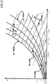
- FIG. 6 showing a simplified Carrier diagram for humid air.
- the transformation "1 ⁇ 2" marked on the diagram can be decomposed into the two transformations “1 ⁇ 3" (latent contribution) and “3 ⁇ 2" (sensible contribution).
- FIG. 7 depicts the complete Carrier diagram of the humid air for the first control region 405.
- the point on the diagram indicated as 1 corresponds to the state of the flow of vapors upon entering into the first control region; the point indicated as 2 corresponds to the state of the flow of vapors upon exiting the first control region.
- the state of the flow of vapors exiting the first control region is rather close to the state indicated as s on the diagram, corresponding to the saturation condition (with relative humidity ⁇ equal to 100%): thus, by spraying cooling water into the first control region, the temperature of the vapors decreases, and the relative humidity ⁇ increases, but the specific humidity x decreases (because the flow of vapors exiting the first control region has a lower content of humidity).
- FIG. 8 depicts the respective humid air Carrier diagram.
- the point 2 on the diagram represents the starting state of the flow of vapors upon entering into the second control region (it corresponds to the point 2 on the Carrier diagram of FIG. 7 ).
- Eq. (10) is the energy balance equation
- Eq. (11) is the mass balance equation.
- Points 5 and 6 represent the states of the flows of hot and dry air entering into the second control region and that are mixed with the flow of vapors: both are characterized by a low relative humidity ⁇ ).
- the third control region is the union of the first and second control regions 405 and 410.
- the energy and mass balance for the third control region can thus be obtained from the above equations.
- the flow of vapors exiting the second control region has a relatively low content of humidity.
- FIG. 9 is a simplified flowchart illustrating a possible way of operation of the oven 100 according to an embodiment of the present invention.
- the oven control unit 423 reads the operation selected by the oven user (block 905 ). The oven control unit 423 then decides whether or not the oven user has selected and started a cooking operation (decision block 910 ). If the oven user has not decided to start a cooking operation (exit branch N of decision block 910 ), the operation flow jumps back to block 905 . If instead the oven user has selected and started a cooking operation (exit branch Y of decision block 910 ), the oven control unit 423 obtains information about the type of cooking selected by the oven user (block 915 ).
- the oven control unit 423 decides whether or not the air propeller 180 is to be activated (block 920 ). If yes, the air propeller 180 is activated, if not, the air propeller 180 is kept off.
- the oven control unit 423 determines (block 921 ) at which pre-set temperature of the vapors entering the vapor exhaust tower 155, the electrovalve 420 is to be activated to enable the intake of cooling water; such determination made by the control unit 423 may be carried out exploiting a database of parameters database, from which the oven control units 423 picks at which pre-set temperature of the vapors entering the vapor exhaust tower 155. Then, by exploiting the readings of the temperature sensor 425, the oven control unit 423 monitors the temperature of the vapors leaving the oven chamber 105 (block 923 ). In particular, the oven control unit 423 checks if such temperature is over the pre-set intervention temperature (block 925 ).
- the oven control unit 423 checks whether the cooking process is terminated (decision block 930 ): if the oven control unit 423 determines that the cooking process is terminated (exit branch Y of decision block 930 ), the oven control unit 423 checks (decision block 931 ) if the electrovalve 420 is currently open: in the affirmative case (exit branch Y of decision block 931 ) the electrovalve 420 is closed (block 933 ); after closing the electrovalve 420 (or leaving it closed, if it was already closed - exit branch N of decision block 931 ), the oven control unit 423 checks (decision block 935 ) whether the fan 180 is running: in the affirmative case (exit branch Y of decision block 935 ), the fan 180 is left running for a predetermined time after the end of the cooking process, whereas if the fan
- the oven control unit 423 determines that the cooking process has not terminated yet (exit branch N of decision block 930 )
- the oven control unit 423 checks whether the electrovalve 420 is activated (decision block 943 ): in the negative case (exit branch N of decision block 943 ), the operation flow returns to block 923, where the oven control unit 423 obtains a new reading of the temperature sensor 425; if instead the oven control unit 423 assesses that the electrovalve 420 is activated (exit branch Y of decision block 943 ), the oven control unit 423 de-activates the electrovalve 420 (block 945 ) and then the operation flow returns to block 923.
- the oven control unit 423 activates the electrovalve 420 (block 950 ); cooling water thus starts to be sprayed by the nozzle 415 into the exhaust tower bottom section 405, to cool the vapors exiting the oven chamber 105.
- the oven control unit 423 determines whether the cooking process has terminated (decision block 955 ): if not (exit branch N of decision block 955 ), the operation flow jumps back to block 923 (where the oven control unit 423 obtains a new reading of the temperature sensor 425; if instead the oven control unit 423 determines that the cooking process has terminated (exit branch Y of decision block 955 ), the oven control unit 423 obtains (through the temperature sensor 425 ) the temperature of the vapors entering into the vapor exhaust tower 155 (block 960 ), and then the oven control unit 423 checks whether the temperature of the vapors exceeds the pre-set intervention temperature (decision block 965 ): until the vapors temperature stays above the pre-set intervention temperature (exit branch Y of decision block 965 ), the electrovalve 420 is kept open, and the oven control unit 423 continues to monitor the vapor temperature.
- the injection of cooling water into the exhaust tower bottom section 405 is selectively enabled based on an assessment of the temperature of the vapors that leaves the oven chamber 105 and enters into the vapor exhaust tower. Also the activation of the fan 180 is selective, depending on the cooking process.
- the vapor exhaust system comprises a sinuous, tortuous, labyrinthic vapors conduit arranged vertically, into which cooling water can (selectively) be injected.
- the tortuous shape of the conduit thanks to the depression generated by a fan downstream the first control region (in the shown example, the fan 180 ) allows exploiting the inertia of the particles of vapor/fat, pushing them against the baffles 177 (in particular, against the first ones, proximate to the bottom of the exhaust tower bottom section 405 ).
- the spray of nebulized cooling water allows capturing the finest particulate (and this effect is also promoted by the baffles 177 proximate to the top of the exhaust tower bottom section 405, which are cooled down by the water spray).
- FIG. 10 there is depicted, schematically as in FIG. 4 , a vapor exhaust tower according to a slightly different embodiment of the present invention; components, parts and elements that are identical, similar or equivalent to those described in connection with the previous embodiment are denoted with same reference numerals.
- a difference of the embodiment of FIG. 10 compared to the previous embodiment resides in that at least part (one, more than one, possibly all) of the baffles 177, like the baffles 1077 visible in the figure, are hollow at their interior and arranged to be run through by a relatively cold heat-exchange fluid 1005 (e.g., liquid, like water), which receives heat released from the vapors passing through the first control volume 405.
- a relatively cold heat-exchange fluid 1005 e.g., liquid, like water
- FIG. 10 Another difference in the embodiment of FIG. 10 compared to the previous embodiment is the different position of the nozzle 415 (which in this embodiment is not at the top of the first control region) and of the temperature sensor 425 (which in this embodiment is not at the bottom of the first control region).
- the nozzle 415 is associated to a lower portion of the bottom section 405 with respect to the temperature sensor 425.
- FIG. 10 just one opening in the exhaust tower top section 410 is shown; this single opening may schematize the two openings 433 and 435 of the previous embodiment, but it might also be possible that through such single opening both of the two cooling air fluxes enter into the vapor exhaust tower. In still other embodiments, one of the two cooling air fluxes might be absent.
- the oven 100 may operate as described in connection with the previous embodiment (flowchart of FIG. 9 ).
Claims (13)
- Procédé pour le traitement de vapeurs produites durant la cuisson d'aliments dans la chambre de four (105) d'un four (100), comprenant les étapes suivantes :la canalisation de vapeurs sortant de ladite chambre de four (105) dans une première région (405) d'un système d'évacuation de vapeurs (155) dudit four (100), agencée pour que, dans celle-ci, les vapeurs soient déshumidifiées et refroidies,dans lequel, dans la première région, un chemin sinueux pour les vapeurs est formé, dans lequel ledit chemin sinueux est une conduite comprenant une pluralité de déflecteurs (177 ; 1077),la déshumidification et le refroidissement desdites vapeurs dans ladite première région (405), dans lequel la déshumidification comprend la pulvérisation d'eau de refroidissement dans la première région où les déflecteurs forment un filtre à chute d'eau qui, à chaque chute, condense les vapeurs,la canalisation desdites vapeurs déshumidifiées et refroidies sortant de ladite première région dans une seconde région (410) dudit système d'évacuation de vapeurs (155), agencée par-dessus ladite première région (405) et agencée pour que, dans celle-ci, des vapeurs sortant de ladite première région soient mélangées à de l'air (140) avant d'être évacuées vers l'environnement ambiant extérieur,dans ledit seconde région (410), le mélange desdites vapeurs déshumidifiées et refroidies sortant de ladite première région avec de l'air aspiré de l'environnement ambiant extérieur et ayant refroidi au moins une parmi une porte (120) dudit four (100) et des parties de four internes chauffées durant le fonctionnement de four,l'évacuation desdites vapeurs vers l'environnement ambiant extérieur.
- Four (100) comprenant une chambre de four (105) pour la cuisson d'aliments, des moyens chauffants (125) pour chauffer la chambre de four, et un système d'évacuation de vapeurs (155) pour traiter des vapeurs produites dans la chambre de four durant un processus de cuisson d'aliments, dans lequel le système d'évacuation de vapeurs comprend :une première région (405) en communication fluidique (160, 165, 170) avec la chambre de four afin de recevoir des vapeurs sortant de la chambre de four et agencée pour que, dans celle-ci, les vapeurs soient déshumidifiées et refroidies, caractérisé en ce queune seconde région (410) en aval de la première région et agencée pour que, dans celle-ci, les vapeurs déshumidifiées et refroidies sortant de la première région soient mélangées à de l'air (140) avant d'être évacuées vers l'environnement ambiant extérieur,dans lequel ladite seconde région (410) est agencée par-dessus la première région (405) et comprend une ou plusieurs entrées (433, 435) agencées pour admettre, dans la seconde région (410), de l'air aspiré de l'environnement ambiant extérieur et exploité pour refroidir au moins une parmi une porte (120) du four et des parties de four internes soumises à un chauffage durant le fonctionnement de four,dans lequel, dans la première région, un chemin sinueux pour les vapeurs est formé, dans lequel ledit chemin sinueux est une conduite comprenant une pluralité de déflecteurs (177 ; 1077),dans lequel ledit four est configuré pour exécuter le procédé de la revendication 1.
- Four selon la revendication 2, dans lequel ladite première région s'étend verticalement.
- Four selon la revendication 2 ou 3, dans lequel au moins un desdits déflecteurs est creux et s'étend à travers un fluide d'échange de chaleur (1005).
- Four selon la revendication 2, 3 ou 4, dans lequel un dispositif d'alimentation en liquide de refroidissement (415, 420) est associé à ladite première région, agencé pour réaliser l'alimentation en un liquide de refroidissement dans la première région pour refroidir les vapeurs.
- Four selon la revendication 5, dans lequel ledit dispositif d'alimentation en liquide de refroidissement comprend au moins une buse d'alimentation en liquide (415) adaptée pour pulvériser un liquide de refroidissement dans ladite première région sous une forme nébulisée.
- Four selon la revendication 5 ou 6, dans lequel ledit dispositif d'alimentation en liquide de refroidissement est agencé pour faire en sorte que le liquide de refroidissement entre dans la première région à proximité d'un côté supérieur de celle-ci.
- Four selon l'une quelconque des revendications 5 à 7, dans lequel ledit dispositif d'alimentation en liquide de refroidissement est raccordé à un activateur adapté pour sélectivement activer ledit dispositif d'alimentation en liquide de refroidissement pour réaliser sélectivement l'alimentation en le liquide de refroidissement.
- Four de l'une quelconque des revendications 5 à 8, dans lequel au moins un capteur de température (425) est associé à la première région, agencé pour détecter la température des vapeurs entrant dans le système d'évacuation de vapeurs.
- Four selon la revendication 9 lorsqu'elle dépend de la revendication 8, dans lequel ledit dispositif d'alimentation en liquide de refroidissement est sélectivement activé sur la base d'une température détectée des vapeurs, détectée par ledit capteur de température.
- Four selon l'une quelconque des revendications 2 à 10, comprenant au moins une roue à aubes à air (180) associée audit système d'évacuation de vapeurs et configurée pour favoriser la sortie de vapeurs à partir de la chambre de four et leur écoulement à travers le système d'évacuation de vapeurs.
- Four selon la revendication 11, dans lequel ladite roue à aubes à air comprend un ventilateur axial ou radial agencé à la sortie du seconde région.
- Four selon la revendication 11 ou 12, dans lequel ladite roue à aubes à air est sélectivement activable.
Priority Applications (2)
| Application Number | Priority Date | Filing Date | Title |
|---|---|---|---|
| EP12169715.5A EP2669583B1 (fr) | 2012-05-29 | 2012-05-29 | Four de cuisson avec un dispositif du traitement de vapeur |
| US13/903,315 US20130333684A1 (en) | 2012-05-29 | 2013-05-28 | Oven for cooking foods |
Applications Claiming Priority (1)
| Application Number | Priority Date | Filing Date | Title |
|---|---|---|---|
| EP12169715.5A EP2669583B1 (fr) | 2012-05-29 | 2012-05-29 | Four de cuisson avec un dispositif du traitement de vapeur |
Publications (2)
| Publication Number | Publication Date |
|---|---|
| EP2669583A1 EP2669583A1 (fr) | 2013-12-04 |
| EP2669583B1 true EP2669583B1 (fr) | 2020-02-12 |
Family
ID=46168288
Family Applications (1)
| Application Number | Title | Priority Date | Filing Date |
|---|---|---|---|
| EP12169715.5A Active EP2669583B1 (fr) | 2012-05-29 | 2012-05-29 | Four de cuisson avec un dispositif du traitement de vapeur |
Country Status (2)
| Country | Link |
|---|---|
| US (1) | US20130333684A1 (fr) |
| EP (1) | EP2669583B1 (fr) |
Families Citing this family (18)
| Publication number | Priority date | Publication date | Assignee | Title |
|---|---|---|---|---|
| EP2240727B1 (fr) * | 2008-01-28 | 2014-12-10 | Duke Manufacturing Company | Four à convection |
| US9080776B2 (en) * | 2008-08-26 | 2015-07-14 | General Electric Company | Fan apparency arrangement for an appliance |
| US9182296B2 (en) * | 2012-05-16 | 2015-11-10 | General Electric Company | Oven air sampling system |
| WO2014190274A1 (fr) | 2013-05-23 | 2014-11-27 | Duke Manufacturing Co. | Appareil et procédés de préparation d'aliment |
| US10918112B2 (en) | 2013-05-23 | 2021-02-16 | Duke Manufacturing Co. | Dough preparation apparatus and methods |
| US9357787B2 (en) | 2013-06-27 | 2016-06-07 | Middleby Marshall Holdings Llc | Forced moisture evacuation for rapid baking |
| US9273880B2 (en) * | 2013-08-14 | 2016-03-01 | Elwha Llc | Heating device with condensing counter-flow heat exchanger |
| US9943211B2 (en) | 2016-04-06 | 2018-04-17 | Whirlpool Corporation | Dishwasher with condensing drying system |
| DE102016215650A1 (de) * | 2016-08-19 | 2018-02-22 | BSH Hausgeräte GmbH | Haushaltsgargerät |
| CN106287856B (zh) * | 2016-09-09 | 2019-03-29 | 美的集团股份有限公司 | 微波烹饪装置 |
| EP3438553A1 (fr) * | 2017-07-31 | 2019-02-06 | Miele & Cie. KG | Appareil de cuisson et procédé |
| TR201712884A2 (tr) * | 2017-08-28 | 2019-03-21 | Arcelik As | Buhar Tahliye Sistemi İçeren Bir Fırın |
| RU2762957C1 (ru) * | 2018-06-07 | 2021-12-24 | Ёунхее ЛИ | Отводное устройство для испарений, выделяемых при приготовлении пищи |
| US10619862B2 (en) * | 2018-06-28 | 2020-04-14 | Whirlpool Corporation | Frontal cooling towers for a ventilation system of a cooking appliance |
| CN111096686B (zh) * | 2018-10-25 | 2022-08-02 | 宁波方太厨具有限公司 | 一种嵌入式烤箱 |
| CN111096685B (zh) * | 2018-10-25 | 2022-07-26 | 宁波方太厨具有限公司 | 一种嵌入式烤箱 |
| CN109875415B (zh) * | 2019-03-15 | 2024-04-09 | 浙江蓝炬星电器有限公司 | 一种高效节能的大型蒸烤箱及其安装方法 |
| DE102022102905A1 (de) | 2022-02-08 | 2023-08-10 | Miele & Cie. Kg | Gargerät mit Wrasenreinigung und Verfahren zum Betreiben des Gargeräts |
Citations (4)
| Publication number | Priority date | Publication date | Assignee | Title |
|---|---|---|---|---|
| DE29602748U1 (de) * | 1996-02-16 | 1996-06-05 | Poetzscher Carola | Einrichtung zur Energierückgewinnung an Backöfen |
| DE102005034303A1 (de) * | 2005-07-22 | 2007-02-01 | Electrolux Home Products Corporation N.V. | Garofen |
| JP2010139177A (ja) * | 2008-12-12 | 2010-06-24 | Mitsubishi Electric Corp | 加熱調理器およびこの加熱調理器を有する誘導加熱調理器 |
| WO2012029691A1 (fr) * | 2010-08-31 | 2012-03-08 | シャープ株式会社 | Cuiseur réchauffeur |
Family Cites Families (12)
| Publication number | Priority date | Publication date | Assignee | Title |
|---|---|---|---|---|
| US4179821A (en) * | 1977-11-21 | 1979-12-25 | General Electric Company | Dishwasher vent arrangement |
| FR2593672B1 (fr) * | 1986-02-05 | 1990-04-27 | Voegtlin Rene | Four de boulangerie a chariot d'enfournement et son procede de vidage de vapeur |
| DE8805455U1 (fr) * | 1988-04-25 | 1988-06-16 | Wiesheu Gmbh, 7151 Affalterbach, De | |
| DE4407702A1 (de) * | 1994-03-08 | 1995-11-30 | Bosch Siemens Hausgeraete | Vorrichtung zum Abführen von Wrasen aus einem Backofen |
| DE4423557C2 (de) | 1994-07-05 | 2001-02-01 | Wiesheu Gmbh | Ofen zur Wärmebehandlung von Lebensmitteln |
| DE19509569A1 (de) * | 1995-03-16 | 1996-09-19 | Wiesheu Wiwa Gmbh | Ofen zur Wärmebehandlung von Lebensmitteln und Verfahren zum Backen |
| US5918589A (en) * | 1996-05-10 | 1999-07-06 | Whirlpool Corporation | Low moisture/closed door broil oven ventilation system |
| DE19720736C2 (de) * | 1997-05-16 | 2003-08-28 | Eloma Gmbh | Gerät zum Garen von Nahrungsmitteln |
| US6761159B1 (en) * | 2003-03-12 | 2004-07-13 | Maytag Corporation | Exhaust cooling system for a cooking appliance |
| DE502006005614D1 (de) * | 2005-10-14 | 2010-01-21 | Max Maier | Dunstabzugshaube für einen kombidämpfer |
| KR100650266B1 (ko) * | 2005-12-19 | 2006-11-27 | 엘지전자 주식회사 | 복합 조리기 시스템 |
| DE102008012961B4 (de) | 2008-03-06 | 2010-02-25 | Mkn Maschinenfabrik Kurt Neubauer Gmbh & Co. | Gargerät mit einer Wrasenkondensiereinrichtung |
-
2012
- 2012-05-29 EP EP12169715.5A patent/EP2669583B1/fr active Active
-
2013
- 2013-05-28 US US13/903,315 patent/US20130333684A1/en not_active Abandoned
Patent Citations (4)
| Publication number | Priority date | Publication date | Assignee | Title |
|---|---|---|---|---|
| DE29602748U1 (de) * | 1996-02-16 | 1996-06-05 | Poetzscher Carola | Einrichtung zur Energierückgewinnung an Backöfen |
| DE102005034303A1 (de) * | 2005-07-22 | 2007-02-01 | Electrolux Home Products Corporation N.V. | Garofen |
| JP2010139177A (ja) * | 2008-12-12 | 2010-06-24 | Mitsubishi Electric Corp | 加熱調理器およびこの加熱調理器を有する誘導加熱調理器 |
| WO2012029691A1 (fr) * | 2010-08-31 | 2012-03-08 | シャープ株式会社 | Cuiseur réchauffeur |
Also Published As
| Publication number | Publication date |
|---|---|
| EP2669583A1 (fr) | 2013-12-04 |
| US20130333684A1 (en) | 2013-12-19 |
Similar Documents
| Publication | Publication Date | Title |
|---|---|---|
| EP2669583B1 (fr) | Four de cuisson avec un dispositif du traitement de vapeur | |
| CA2458994C (fr) | Systeme de regulation d'humidite pour four combine | |
| US8418684B2 (en) | Catalytic converter unit and method for treating cooking emissions | |
| KR101934903B1 (ko) | 식품 조리 장치 | |
| RU2313035C2 (ru) | Печь(варианты), способ охлаждения дверцы печи, сборочный узел для регулирования воздуха и сборочный узел печи | |
| RU2401960C2 (ru) | Нагревательная печь | |
| CN113924447A (zh) | 用于加热烹饪物品的装置 | |
| CN110115516B (zh) | 具有可变容积的蒸汽辅助式烹饪区的多区烤箱 | |
| US7282674B2 (en) | System and method for limiting the escape of heat and steam from an open oven door | |
| US10477867B2 (en) | Oven appliance with air curtain | |
| CN110115517B (zh) | 用于多区烤箱的组合排放系统 | |
| CN101657140A (zh) | 用于洗碗机的干燥系统 | |
| CN103155960A (zh) | 具有催化转换器的组合式烤箱 | |
| JP2008008539A (ja) | 加熱調理器 | |
| US6904903B1 (en) | Convection steamer with forced recirculation through steam bath | |
| JP2016031202A (ja) | 加熱調理器 | |
| WO2007013408A1 (fr) | Cuisinière de chauffage et plateau idoine | |
| CN109690194B (zh) | 烤箱 | |
| US20090025704A1 (en) | Systems and methods for heating food | |
| JP2008032286A (ja) | 加熱調理器 | |
| CN114901895A (zh) | 衣物处理装置 | |
| CN112020626B (zh) | 烹饪烟雾排出装置 | |
| EP2458069B1 (fr) | Sèche-linge disposant d'un système de protection contre les incendies | |
| JP2012007831A (ja) | 室内循環型レンジフード | |
| JP2018158062A (ja) | グリル調理機器及びそれを搭載した加熱調理機器 |
Legal Events
| Date | Code | Title | Description |
|---|---|---|---|
| PUAI | Public reference made under article 153(3) epc to a published international application that has entered the european phase |
Free format text: ORIGINAL CODE: 0009012 |
|
| AK | Designated contracting states |
Kind code of ref document: A1 Designated state(s): AL AT BE BG CH CY CZ DE DK EE ES FI FR GB GR HR HU IE IS IT LI LT LU LV MC MK MT NL NO PL PT RO RS SE SI SK SM TR |
|
| AX | Request for extension of the european patent |
Extension state: BA ME |
|
| 17P | Request for examination filed |
Effective date: 20140604 |
|
| RBV | Designated contracting states (corrected) |
Designated state(s): AL AT BE BG CH CY CZ DE DK EE ES FI FR GB GR HR HU IE IS IT LI LT LU LV MC MK MT NL NO PL PT RO RS SE SI SK SM TR |
|
| 17Q | First examination report despatched |
Effective date: 20160331 |
|
| STAA | Information on the status of an ep patent application or granted ep patent |
Free format text: STATUS: EXAMINATION IS IN PROGRESS |
|
| GRAP | Despatch of communication of intention to grant a patent |
Free format text: ORIGINAL CODE: EPIDOSNIGR1 |
|
| STAA | Information on the status of an ep patent application or granted ep patent |
Free format text: STATUS: GRANT OF PATENT IS INTENDED |
|
| INTG | Intention to grant announced |
Effective date: 20191011 |
|
| GRAS | Grant fee paid |
Free format text: ORIGINAL CODE: EPIDOSNIGR3 |
|
| GRAA | (expected) grant |
Free format text: ORIGINAL CODE: 0009210 |
|
| STAA | Information on the status of an ep patent application or granted ep patent |
Free format text: STATUS: THE PATENT HAS BEEN GRANTED |
|
| AK | Designated contracting states |
Kind code of ref document: B1 Designated state(s): AL AT BE BG CH CY CZ DE DK EE ES FI FR GB GR HR HU IE IS IT LI LT LU LV MC MK MT NL NO PL PT RO RS SE SI SK SM TR |
|
| REG | Reference to a national code |
Ref country code: GB Ref legal event code: FG4D |
|
| REG | Reference to a national code |
Ref country code: CH Ref legal event code: EP |
|
| REG | Reference to a national code |
Ref country code: AT Ref legal event code: REF Ref document number: 1232612 Country of ref document: AT Kind code of ref document: T Effective date: 20200215 |
|
| REG | Reference to a national code |
Ref country code: DE Ref legal event code: R096 Ref document number: 602012067644 Country of ref document: DE |
|
| REG | Reference to a national code |
Ref country code: IE Ref legal event code: FG4D |
|
| PG25 | Lapsed in a contracting state [announced via postgrant information from national office to epo] |
Ref country code: RS Free format text: LAPSE BECAUSE OF FAILURE TO SUBMIT A TRANSLATION OF THE DESCRIPTION OR TO PAY THE FEE WITHIN THE PRESCRIBED TIME-LIMIT Effective date: 20200212 Ref country code: FI Free format text: LAPSE BECAUSE OF FAILURE TO SUBMIT A TRANSLATION OF THE DESCRIPTION OR TO PAY THE FEE WITHIN THE PRESCRIBED TIME-LIMIT Effective date: 20200212 Ref country code: NO Free format text: LAPSE BECAUSE OF FAILURE TO SUBMIT A TRANSLATION OF THE DESCRIPTION OR TO PAY THE FEE WITHIN THE PRESCRIBED TIME-LIMIT Effective date: 20200512 |
|
| REG | Reference to a national code |
Ref country code: LT Ref legal event code: MG4D |
|
| REG | Reference to a national code |
Ref country code: NL Ref legal event code: MP Effective date: 20200212 |
|
| PG25 | Lapsed in a contracting state [announced via postgrant information from national office to epo] |
Ref country code: HR Free format text: LAPSE BECAUSE OF FAILURE TO SUBMIT A TRANSLATION OF THE DESCRIPTION OR TO PAY THE FEE WITHIN THE PRESCRIBED TIME-LIMIT Effective date: 20200212 Ref country code: SE Free format text: LAPSE BECAUSE OF FAILURE TO SUBMIT A TRANSLATION OF THE DESCRIPTION OR TO PAY THE FEE WITHIN THE PRESCRIBED TIME-LIMIT Effective date: 20200212 Ref country code: LV Free format text: LAPSE BECAUSE OF FAILURE TO SUBMIT A TRANSLATION OF THE DESCRIPTION OR TO PAY THE FEE WITHIN THE PRESCRIBED TIME-LIMIT Effective date: 20200212 Ref country code: BG Free format text: LAPSE BECAUSE OF FAILURE TO SUBMIT A TRANSLATION OF THE DESCRIPTION OR TO PAY THE FEE WITHIN THE PRESCRIBED TIME-LIMIT Effective date: 20200512 Ref country code: IS Free format text: LAPSE BECAUSE OF FAILURE TO SUBMIT A TRANSLATION OF THE DESCRIPTION OR TO PAY THE FEE WITHIN THE PRESCRIBED TIME-LIMIT Effective date: 20200612 Ref country code: GR Free format text: LAPSE BECAUSE OF FAILURE TO SUBMIT A TRANSLATION OF THE DESCRIPTION OR TO PAY THE FEE WITHIN THE PRESCRIBED TIME-LIMIT Effective date: 20200513 |
|
| PG25 | Lapsed in a contracting state [announced via postgrant information from national office to epo] |
Ref country code: NL Free format text: LAPSE BECAUSE OF FAILURE TO SUBMIT A TRANSLATION OF THE DESCRIPTION OR TO PAY THE FEE WITHIN THE PRESCRIBED TIME-LIMIT Effective date: 20200212 |
|
| PG25 | Lapsed in a contracting state [announced via postgrant information from national office to epo] |
Ref country code: RO Free format text: LAPSE BECAUSE OF FAILURE TO SUBMIT A TRANSLATION OF THE DESCRIPTION OR TO PAY THE FEE WITHIN THE PRESCRIBED TIME-LIMIT Effective date: 20200212 Ref country code: CZ Free format text: LAPSE BECAUSE OF FAILURE TO SUBMIT A TRANSLATION OF THE DESCRIPTION OR TO PAY THE FEE WITHIN THE PRESCRIBED TIME-LIMIT Effective date: 20200212 Ref country code: EE Free format text: LAPSE BECAUSE OF FAILURE TO SUBMIT A TRANSLATION OF THE DESCRIPTION OR TO PAY THE FEE WITHIN THE PRESCRIBED TIME-LIMIT Effective date: 20200212 Ref country code: LT Free format text: LAPSE BECAUSE OF FAILURE TO SUBMIT A TRANSLATION OF THE DESCRIPTION OR TO PAY THE FEE WITHIN THE PRESCRIBED TIME-LIMIT Effective date: 20200212 Ref country code: SM Free format text: LAPSE BECAUSE OF FAILURE TO SUBMIT A TRANSLATION OF THE DESCRIPTION OR TO PAY THE FEE WITHIN THE PRESCRIBED TIME-LIMIT Effective date: 20200212 Ref country code: SK Free format text: LAPSE BECAUSE OF FAILURE TO SUBMIT A TRANSLATION OF THE DESCRIPTION OR TO PAY THE FEE WITHIN THE PRESCRIBED TIME-LIMIT Effective date: 20200212 Ref country code: DK Free format text: LAPSE BECAUSE OF FAILURE TO SUBMIT A TRANSLATION OF THE DESCRIPTION OR TO PAY THE FEE WITHIN THE PRESCRIBED TIME-LIMIT Effective date: 20200212 Ref country code: PT Free format text: LAPSE BECAUSE OF FAILURE TO SUBMIT A TRANSLATION OF THE DESCRIPTION OR TO PAY THE FEE WITHIN THE PRESCRIBED TIME-LIMIT Effective date: 20200705 Ref country code: ES Free format text: LAPSE BECAUSE OF FAILURE TO SUBMIT A TRANSLATION OF THE DESCRIPTION OR TO PAY THE FEE WITHIN THE PRESCRIBED TIME-LIMIT Effective date: 20200212 |
|
| REG | Reference to a national code |
Ref country code: DE Ref legal event code: R097 Ref document number: 602012067644 Country of ref document: DE |
|
| REG | Reference to a national code |
Ref country code: AT Ref legal event code: MK05 Ref document number: 1232612 Country of ref document: AT Kind code of ref document: T Effective date: 20200212 |
|
| PLBE | No opposition filed within time limit |
Free format text: ORIGINAL CODE: 0009261 |
|
| STAA | Information on the status of an ep patent application or granted ep patent |
Free format text: STATUS: NO OPPOSITION FILED WITHIN TIME LIMIT |
|
| 26N | No opposition filed |
Effective date: 20201113 |
|
| PG25 | Lapsed in a contracting state [announced via postgrant information from national office to epo] |
Ref country code: AT Free format text: LAPSE BECAUSE OF FAILURE TO SUBMIT A TRANSLATION OF THE DESCRIPTION OR TO PAY THE FEE WITHIN THE PRESCRIBED TIME-LIMIT Effective date: 20200212 Ref country code: MC Free format text: LAPSE BECAUSE OF FAILURE TO SUBMIT A TRANSLATION OF THE DESCRIPTION OR TO PAY THE FEE WITHIN THE PRESCRIBED TIME-LIMIT Effective date: 20200212 Ref country code: CH Free format text: LAPSE BECAUSE OF NON-PAYMENT OF DUE FEES Effective date: 20200531 Ref country code: LI Free format text: LAPSE BECAUSE OF NON-PAYMENT OF DUE FEES Effective date: 20200531 |
|
| PG25 | Lapsed in a contracting state [announced via postgrant information from national office to epo] |
Ref country code: SI Free format text: LAPSE BECAUSE OF FAILURE TO SUBMIT A TRANSLATION OF THE DESCRIPTION OR TO PAY THE FEE WITHIN THE PRESCRIBED TIME-LIMIT Effective date: 20200212 Ref country code: PL Free format text: LAPSE BECAUSE OF FAILURE TO SUBMIT A TRANSLATION OF THE DESCRIPTION OR TO PAY THE FEE WITHIN THE PRESCRIBED TIME-LIMIT Effective date: 20200212 |
|
| REG | Reference to a national code |
Ref country code: BE Ref legal event code: MM Effective date: 20200531 |
|
| GBPC | Gb: european patent ceased through non-payment of renewal fee |
Effective date: 20200529 |
|
| PG25 | Lapsed in a contracting state [announced via postgrant information from national office to epo] |
Ref country code: LU Free format text: LAPSE BECAUSE OF NON-PAYMENT OF DUE FEES Effective date: 20200529 |
|
| PG25 | Lapsed in a contracting state [announced via postgrant information from national office to epo] |
Ref country code: GB Free format text: LAPSE BECAUSE OF NON-PAYMENT OF DUE FEES Effective date: 20200529 Ref country code: FR Free format text: LAPSE BECAUSE OF NON-PAYMENT OF DUE FEES Effective date: 20200531 Ref country code: IE Free format text: LAPSE BECAUSE OF NON-PAYMENT OF DUE FEES Effective date: 20200529 |
|
| PG25 | Lapsed in a contracting state [announced via postgrant information from national office to epo] |
Ref country code: BE Free format text: LAPSE BECAUSE OF NON-PAYMENT OF DUE FEES Effective date: 20200531 |
|
| PG25 | Lapsed in a contracting state [announced via postgrant information from national office to epo] |
Ref country code: TR Free format text: LAPSE BECAUSE OF FAILURE TO SUBMIT A TRANSLATION OF THE DESCRIPTION OR TO PAY THE FEE WITHIN THE PRESCRIBED TIME-LIMIT Effective date: 20200212 Ref country code: MT Free format text: LAPSE BECAUSE OF FAILURE TO SUBMIT A TRANSLATION OF THE DESCRIPTION OR TO PAY THE FEE WITHIN THE PRESCRIBED TIME-LIMIT Effective date: 20200212 Ref country code: CY Free format text: LAPSE BECAUSE OF FAILURE TO SUBMIT A TRANSLATION OF THE DESCRIPTION OR TO PAY THE FEE WITHIN THE PRESCRIBED TIME-LIMIT Effective date: 20200212 |
|
| PG25 | Lapsed in a contracting state [announced via postgrant information from national office to epo] |
Ref country code: MK Free format text: LAPSE BECAUSE OF FAILURE TO SUBMIT A TRANSLATION OF THE DESCRIPTION OR TO PAY THE FEE WITHIN THE PRESCRIBED TIME-LIMIT Effective date: 20200212 Ref country code: AL Free format text: LAPSE BECAUSE OF FAILURE TO SUBMIT A TRANSLATION OF THE DESCRIPTION OR TO PAY THE FEE WITHIN THE PRESCRIBED TIME-LIMIT Effective date: 20200212 |
|
| P01 | Opt-out of the competence of the unified patent court (upc) registered |
Effective date: 20230526 |
|
| PGFP | Annual fee paid to national office [announced via postgrant information from national office to epo] |
Ref country code: IT Payment date: 20230418 Year of fee payment: 12 Ref country code: DE Payment date: 20230417 Year of fee payment: 12 |