EP2669436B1 - Ramm- und Ziehvorrichtung - Google Patents
Ramm- und Ziehvorrichtung Download PDFInfo
- Publication number
- EP2669436B1 EP2669436B1 EP20120170034 EP12170034A EP2669436B1 EP 2669436 B1 EP2669436 B1 EP 2669436B1 EP 20120170034 EP20120170034 EP 20120170034 EP 12170034 A EP12170034 A EP 12170034A EP 2669436 B1 EP2669436 B1 EP 2669436B1
- Authority
- EP
- European Patent Office
- Prior art keywords
- accordance
- carriage
- ram
- cells
- coupling part
- Prior art date
- Legal status (The legal status is an assumption and is not a legal conclusion. Google has not performed a legal analysis and makes no representation as to the accuracy of the status listed.)
- Revoked
Links
Images


Classifications
-
- E—FIXED CONSTRUCTIONS
- E02—HYDRAULIC ENGINEERING; FOUNDATIONS; SOIL SHIFTING
- E02D—FOUNDATIONS; EXCAVATIONS; EMBANKMENTS; UNDERGROUND OR UNDERWATER STRUCTURES
- E02D3/00—Improving or preserving soil or rock, e.g. preserving permafrost soil
- E02D3/02—Improving by compacting
- E02D3/08—Improving by compacting by inserting stones or lost bodies, e.g. compaction piles
Definitions
- the invention relates to a device for introducing a Hinttelstopfklale in a subsoil according to claim 1.
- a vibrator which is guided on a leader, is applied to the pipe to be introduced and firmly connected to the pipe.
- this compound is burdened by bending moments caused by the lateral drifting of the pipe in the ground.
- the vibrator transmits the bending moments to the leader via the guides with which he is connected to the leader.
- the bending moments load the connection between the vibrator and the tube, the guides between the vibrator and the leader and the leader himself.
- the filling of the tube usually takes place only after introduction of the tube into the ground on the supporting layer, since the filling is the easiest way via a hopper by means of an excavator or the like.
- the filling is hindered by the inserted vibrator, which is located above the funnel.
- the invention aims to remedy this situation.
- the invention is based on the object to provide a device for introducing a Hinttelstopfklale in a ground, which allows a simplified handling of the tube and its filling and in which the connection between the vibrator and pipe is not burdened by bending moments. According to the invention, this object is solved by the features of claim 1.
- the invention provides a device for ramming or pulling a Rammgutes, especially a Rüttelstopflanze created in or from the ground, which allows a simplified handling of the tube and its filling and in the connection between the vibrator and tube or tubular lance not through Bending moments, resulting from the possible lateral drifting of the pipe in the ground, is charged.
- the at least two exciter cells which together give a vibrator, are connected via a coupling part with the tubular lance.
- the at least two excitation cells are designed so that their unbalance masses synchronize themselves during the rotation, in such a way that the vertical force components add and largely eliminate the horizontal force components. As a result, a resultant force is achieved substantially parallel to the effective direction.
- each excitation cell is provided with a separate rotary drive which is designed to rotate the at least one imbalance mass of the respective exciter cell.
- means for stabilizing the synchronous operation of the at least two exciter cells are arranged.
- electrical stabilizers can be used.
- controlled settling of the exciter cells is possible.
- the coupling part is connected to a carriage, via which it is displaceably mounted along a Gurklers.
- the device can be coupled as work equipment directly without the need for additional components to a leader.
- the carriage is connected to a guided on the leader base slide, which is acted upon by a drive with tensile and / or compressive forces.
- the base carriage is preferably resiliently connected via flexible elements, in particular elastomers with the carriage.
- a console is attached to the base carriage, which is provided with flexible elements, in particular elastomers, via which the console is connected to the carriage. This makes it possible to apply the Rammgut with simultaneous vibration damping with a biasing or pulling force, which is applied by the broker.
- a hopper for filling the lance is arranged, which is connected via damping elements with the coupling part or the tubular lance.
- the design of such a one-piece lance with integrated filling unit enables easy positioning and insertion of the lance into the ground with simultaneous introduction of filling material into the lance.
- the lance has a flange which is screwed to a provided on the coupling part flange.
- the funnel is further connected to the carriage via damping elements.
- the tubular lance is double-walled.
- a connection for acting on the cavity formed between the two walls is arranged with compressed air.
- the croquttelstopfvorraum chosen as an embodiment consists essentially of a coupling part 1, which is connected to a carriage 2 and provided with two oppositely arranged exciter cells 3.
- the coupling part 1 is fixedly connected to a tubular lance 4 and the lance 4 is resiliently connected to a funnel 5 for filling the lance 4 opposite.
- the coupling part 1 is guided via the carriage 2 on a broker 8, which is connected via a console 6 with the base carriage 7 of the leader 8.
- the coupling part 1 is formed by a substantially rectangular base plate 11 which has a central flange 12 for fixing the lance 4.
- the flange 12 opposite to the inlet plate 13 is arranged on the base plate 11, which is fixed on both sides via two vertical support plates 14.
- the holding plates 14 are at the same time with the base plate 11 receptacles 15 for the exciter cells 3.
- the coupling part 1 is connected by welding to the carriage 2.
- the carriage 2 consists essentially of a cuboid frame 21 which is provided on the back with guide elements 22 for receiving the leader rails 81. On its side opposite the guide elements 22 are further attached to the carriage 2, two end opposite cantilevered outward wings 23 for resilient attachment of the funnel 5 via damping elements 51.
- the carriage 2 is resiliently connected via inside the frame 21 in pairs oppositely disposed elastomeric blocks 24 with the console 6, which penetrates the frame 21 of the carriage 2 along its central axis.
- the console 6 consists essentially of a rectangular profile, at its opposite ends of the carriage 2 is provided a connection piece 62 for connection to the Telklercampusschlitten 7.
- the excitation cells 3 each comprise a housing 31 in which a - not shown - rotatably mounted shaft is arranged, which is provided with a - not shown - imbalance mass.
- the shaft is connected to a rotary drive 32 which is fixed to the respective housing 31.
- the excitation cells formed in this way are attached to the base plate 11 of the coupling part 1 on both sides of the inlet nozzle 13 adjacent to the respectively associated holding plate 14.
- the lance 4 is formed in the embodiment as a cylindrical tube, on whose the coupling part 1 facing the end of a flange 41 is formed.
- the flange 41 is bolted to the flange 12 of the coupling part 1.
- the hopper 5 is connected via damping elements 51 to the inlet port 13 and elastomer blocks 24 to the frame 21 of the carriage 2.
- the base carriage 7 is connected via a bolt lock 71 with the connector 62 of the console 6.
- mounting plates 72 are attached to the base carriage 7 for attachment of tension cables (not shown) via which the base carriage 7 can be subjected to pressure or tensile forces.
Landscapes
- Engineering & Computer Science (AREA)
- Structural Engineering (AREA)
- Life Sciences & Earth Sciences (AREA)
- General Life Sciences & Earth Sciences (AREA)
- Soil Sciences (AREA)
- Environmental & Geological Engineering (AREA)
- Agronomy & Crop Science (AREA)
- Mining & Mineral Resources (AREA)
- Paleontology (AREA)
- Civil Engineering (AREA)
- General Engineering & Computer Science (AREA)
- Investigation Of Foundation Soil And Reinforcement Of Foundation Soil By Compacting Or Drainage (AREA)
- Revetment (AREA)
Description
- Die Erfindung betrifft eine Vorrichtung zur Einbringung einer Rüttelstopfsäule in einen Baugrund nach dem Patentanspruch 1.
- Zur Erhöhung der Tragfähigkeit eines Baugrunds ist es z.B. aus der
DE 10 2004 013 790 A bekannt, diesen durch das Verfahren der Rüttelstopfverdichtung zu verbessern. Dabei werden in die Last aufzunehmenden Bereiche des Baugrunds so genannten Rüttelstopfsäulen eingebracht. Dies geschieht, in dem ein Rohr, auf den Baugrund aufgesetzt wird und mittels eines Vibrators bis auf den tragenden Grund eingebracht wird, wobei das lockere Erdreich seitlich verdrängt wird. Das Rohr wird mit geeignetem Zugabematerial, wie Kies oder Schotter befüllt und anschließend gezogen, wobei fortlaufend an der dem Grund zugewandten Seite des Rohres Material austritt, dass durch mehrfaches alternierendes Absenken des Rohres weiter verdichtet wird. Hierdurch wird im Boden eine Säule aus dem verdichteten Zugabematerial hergestellt, welche als Rüttelstopfsäule bezeichnet wird. - Bei dem vorgenannten Verfahren wird ein Vibrator, der an einem Mäkler geführt ist, an das einzubringende Rohr angelegt und fest mit dem Rohr verbunden. In der Praxis ist diese Verbindung durch Biegemomente belastet, die durch das seitliche Abdriften des Rohres im Boden entstehen. Der Vibrator überträgt die Biegemomente über die Führungen, mit denen er mit dem Mäkler verbunden ist, auf den Mäkler. Somit werden durch die Biegemomente die Verbindung zwischen Vibrator und Rohr, die Führungen zwischen Vibrator und Mäkler sowie der Mäkler selbst belastet.
- Darüber hinaus erfolgt die Befüllung des Rohres meist erst nach Einbringung des Rohres in den Baugrund auf die tragende Schicht, da hier die Befüllung über einen Trichter mittels eines Baggers oder ähnlichen am einfachsten ist. Die Befüllung wird dabei durch den eingesetzten Vibrator, der sich oberhalb des Trichters befindet, behindert.
- Hier will die Erfindung Abhilfe schaffen. Der Erfindung liegt die Aufgabe zu Grunde, eine Vorrichtung zur Einbringung einer Rüttelstopfsäule in einen Baugrund zu schaffen, welche eine vereinfachte Handhabung des Rohres sowie dessen Befüllung ermöglicht und bei der die Verbindung zwischen Vibrator und Rohr nicht durch Biegemomente belastet wird. Gemäß der Erfindung wird diese Aufgabe durch die Merkmale des Patentanspruchs 1 gelöst.
- Mit der Erfindung ist eine Vorrichtung zum Rammen oder Ziehen eines Rammgutes, insbesondere einer Rüttelstopflanze in den bzw. aus dem Boden geschaffen, die eine vereinfachte Handhabung des Rohres sowie dessen Befüllung ermöglicht und bei der die Verbindung zwischen Vibrator und Rohr bzw. rohrförmiger Lanze nicht durch Biegemomente, die aus dem möglichen seitlichen Wegdriften des Rohrs im Boden resultieren, belastet wird. Die wenigstens zwei Erregerzellen, die zusammen einen Vibrator ergeben, sind über ein Koppelteil mit der rohrförmigen Lanze verbunden. Weiterhin sind die wenigstens zwei Erregerzellen so ausgeführt, dass sich ihre Unwuchtmassen bei der Rotation selbst synchronisieren, und zwar derart, dass sich die vertikalen Kraftanteile addieren und die horizontalen Kraftanteile weitgehend eliminieren. Hierdurch ist eine resultierende Kraft im Wesentlichen parallel zur Wirkrichtung erzielt.
- Bevorzugt sind genau zwei Erregerzellen angeordnet, wobei vorzugsweise jede Erregerzelle mit einem separaten Drehantrieb versehen ist, der derart ausgelegt ist, die wenigstens eine Unwuchtmasse der jeweiligen Erregerzelle zu drehen.
- In Weiterbildung der Erfindung sind Mittel zur Stabilisierung des Synchronbetriebs der wenigstens zwei Erregerzellen angeordnet. Hierzu können insbesondere elektrische Stabilisatoren zum Einsatz kommen. Hierdurch ist gesteuertes Einschwingen der Erregerzellen ermöglicht.
- In Ausgestaltung der Erfindung ist das Koppelteil mit einem Schlitten verbunden, über den es entlang eines Mäklers verschiebbar gelagert ist. Hierdurch ist die Vorrichtung als Arbeitsgerät direkt ohne das Erfordernis weiterer Bauteile an einen Mäkler ankoppelbar.
- In weiterer Ausgestaltung der Erfindung ist der Schlitten mit einem auf dem Mäkler geführten Grundschlitten verbunden, der über einen Antrieb mit Zug- und/oder Druckkräften beaufschlagbar ist. Dabei ist der Grundschlitten bevorzugt über flexible Elemente, insbesondere Elastomere mit dem Schlitten federnd verbunden. Hierdurch ist die Übertragung der von den Erregerzellen erzeugten Schwingungen auf den Mäklern vermindert.
- In weiterer Ausgestaltung der Erfindung ist an dem Grundschlitten eine Konsole befestigt, welche mit flexiblen Elementen, insbesondere Elastomeren, versehen ist, über welche die Konsole mit dem Schlitten verbunden ist. Hierdurch ist es möglich, das Rammgut bei gleichzeitiger Schwingungsdämpfung mit einer Vorspann- oder Zugkraft, die vom Mäkler aufgebracht wird, zu beaufschlagen.
- In weiterer Ausgestaltung der Erfindung ist ein Fülltrichter zur Befüllung der Lanze angeordnet, der über Dämpfungselemente mit dem Koppelteil bzw. der rohrförmigen Lanze verbunden ist. Durch die Ausgestaltung einer solchen einteiligen Lanze mit integrierter Einfülleinheit ist eine einfache Positionierung und Einbringung der Lanze in den Baugrund bei gleichzeitiger Einbringung von Füllmaterial in die Lanze ermöglicht. Bevorzugt weist die Lanze einen Flansch auf, der mit einem an dem Koppelteil vorgesehenen Flansch verschraubt ist. Vorteilhaft ist der Trichter über Dämpfungselemente weiterhin mit dem Schlitten verbunden.
- In weiterer Ausgestaltung der Erfindung ist die rohrförmige Lanze doppelwandig ausgebildet. Bevorzugt ist ein Anschluss zur Beaufschlagung des zwischen den beiden Wänden gebildeten Hohlraums mit Pressluft angeordnet. Bei der Rüttelstopfverdichtung von Gewässergründen ist so eine steuerbare Erhöhung des Auftriebs der Lanze in dem Gewässer ermöglicht, wodurch die von dem Trägergerät zu erbringende Zugleistung erheblich gemindert werden kann. Insbesondere für Baugrundverbesserungsmaßnahmen in Gewässern weist die Wandung in einer weiteren Ausbildung der Erfindung seitliche Öffnungen auf. Diese Öffnungen dienen dem Austritt von durch eingebrachtes Stopfmaterial verdrängtem Wasser. Hierdurch ist der Rüttelstopfprozess weiter verbessert.
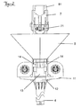
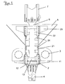
- Andere Weiterbildungen und Ausgestaltungen der Erfindung sind in den übrigen Unteransprüchen angegeben. Ein Ausführungsbeispiel der Erfindung ist in den Zeichnungen dargestellt und wird nachfolgend im Einzelnen beschrieben. Es zeigen:
- Figur 1
- die schematische Darstellung einer Vorrichtung zur Einbringung einer Rüttelstopfsäule in den Boden;
- Figur 2
- die Darstellung der Vorrichtung aus
Figur 1 in der Vorderansicht; - Figur 3
- die Darstellung der Vorrichtung aus
Figur 1 in der Ansicht von hinten und - Figur 4
- die Darstellung der Vorrichtung aus
Figur 1 in einer weiteren räumlichen Ansicht. - Die als Ausführungsbeispiel gewählte Rüttelstopfvorrichtung besteht im Wesentlichen aus einem Koppelteil 1, das mit einem Schlitten 2 verbunden und mit zwei gegenüberliegend angeordneten Erregerzellen 3 versehen ist. Das Koppelteil 1 ist mit einer rohrförmigen Lanze 4 fest verbunden und der Lanze 4 gegenüberliegend federnd mit einen Trichter 5 zur Befüllung der Lanze 4 verbunden. Das Koppelteil 1 ist über den Schlitten 2 auf einem Mäkler 8 geführt, der über eine Konsole 6 mit dem Grundschlitten 7 des Mäklers 8 verbunden ist.
- Das Koppelteil 1 ist gebildet durch eine im Wesentlichen rechteckig ausgebildete Grundplatte 11 die mittig einen Flansch 12 zur Befestigung der Lanze 4 aufweist. Dem Flansch 12 gegenüberliegend ist auf der Grundplatte 11 ein Einlassstutzen 13 angeordnet, der beidseitig über zwei vertikale Halteplatten 14 fixiert ist. Die Halteplatten 14 sind gleichzeitig mit der Grundplatte 11 Aufnahmen 15 für die Erregerzellen 3. Das Koppelteil 1 ist durch Schweißverbindungen mit dem Schlitten 2 verbunden.
- Der Schlitten 2 besteht im Wesentlichen aus einem quaderförmigen Rahmen 21, der Rückseitig mit Führungselementen 22 zur Aufnahme der Mäklerschienen 81 versehen ist. An seiner den Führungselementen 22 gegenüberliegenden Seite sind an dem Schlitten 2 weiterhin zwei endseitig gegenüberliegend nach außen kragende Flügel 23 zur federnden Befestigung des Trichters 5 über Dämpfungselemente 51 angebracht. Der Schlitten 2 ist über innerhalb des Rahmens 21 paarweise gegenüberliegend angeordnete Elastomerblöcke 24 mit der Konsole 6 federnd verbunden, welche den Rahmen 21 des Schlittens 2 entlang seiner Mittelachse durchdringt.
- Die Konsole 6 besteht im Wesentlichen aus einem Rechteckprofil, an dessen dem Schlitten 2 gegenüberliegenden Enden einem Anschlussstück 62 zur Verbindung mit dem Mäklergrundschlitten 7 versehen ist. Die Erregerzellen 3 umfassen jeweils ein Gehäuse 31 in dem eine - nicht dargestellte - drehbar gelagerte Welle angeordnet ist, die mit einer - nicht dargestellten - Unwuchtmasse versehen ist. Die Welle ist mit einem Drehantrieb 32 verbunden, der an dem jeweiligen Gehäuse 31 befestigt ist. Die so ausgebildeten Erregerzellen sind auf der Grundplatte 11 des Koppelteils 1 beidseitig des Einlassstutzens 13 an der jeweils zugeordneten Halteplatte 14 anliegend befestigt.
- Die Lanze 4 ist im Ausführungsbeispiel als zylindrisches Rohr ausgebildet, an dessen dem Koppelteil 1 zugewandten Ende ein Flansch 41 angeformt ist. Der Flansch 41 ist mit dem Flansch 12 des Koppelteils 1 verschraubt.
- Der Trichter 5 ist über Dämpfungselemente 51 mit dem Einlassstutzen 13 sowie über Elastomerblöcke 24 mit dem Rahmen 21 des Schlittens 2 verbunden.
- Der Grundschlitten 7 ist über eine Bolzenverriegelung 71 mit dem Anschlussstück 62 der Konsole 6 verbunden. Beidseitig der Bolzenverriegelung 71 sind an dem Grundschlitten 7 Aufnahmeplatten 72 zur Befestigung von - nicht dargestellten - Zugseilen angebracht, über welche der Grundschlitten 7 mit Druck- bzw. Zugkräften beaufschlagbar ist.
Claims (12)
- Vorrichtung zum Einbringen einer Rüttelstopfsäule in einen Baugrund, mit einer rohrförmigen Lanze (4), die mit einem Koppelteil (1) verbunden ist, an dem radial um die Mittelachse der Lanze (4) verteilt wenigstens zwei Erregerzellen (3) befestigt sind, welche jeweils ein Gehäuse (31) aufweisen, in dem wenigstens eine Welle mit wenigstens einer Unwuchtmasse angeordnet ist, die mit wenigstens einem Drehantrieb (32) verbunden ist, dadurch gekennzeichnet, dass die wenigstens zwei Erregerzellen (3) derart ausgerichtet sind, dass sich die Unwuchten der Erregerzellen (3) im Betrieb selbst synchronisieren.
- Vorrichtung nach Anspruch 1, dadurch gekennzeichnet, dass genau zwei einwellige Erregerzellen (3) angeordnet sind.
- Vorrichtung nach Anspruch 1 oder 2, dadurch gekennzeichnet, dass Mittel zur Stabilisierung des Synchronbetriebs der wenigstens zwei Erregerzellen (3) angeordnet sind.
- Vorrichtung nach einem der vorgenannten Ansprüche, dadurch gekennzeichnet, dass das Koppelteil (1) mit einem Schlitten (2) verbunden ist, über den es entlang eines Mäklers (8) verschiebbar gelagert ist.
- Vorrichtung nach Anspruch 4, dadurch gekennzeichnet, dass der Schlitten (2) mit einem auf dem Mäkler (8) geführten Grundschlitten (7) verbunden ist, der über einen Antrieb mit Zug- und/oder Druckkräften beaufschlagbar ist.
- Vorrichtung nach Anspruch 5, dadurch gekennzeichnet, dass der Grundschlitten (7) über flexible Elemente, insbesondere Elastomere (24) mit dem Schlitten (2) federnd verbunden ist.
- Vorrichtung nach Anspruch 6, dadurch gekennzeichnet, dass an dem Grundschlitten (7) eine Konsole (6) befestigt ist, welche mit flexiblen Elementen, insbesondere Elastomeren (24) versehen ist, über welche die Konsole (6) mit dem Schlitten (2) verbunden ist.
- Vorrichtung nach einem der vorgenannten Ansprüche, dadurch gekennzeichnet, dass ein Fülltrichter (5) zur Beschickung der Lanze (4) angeordnet ist, der über Dämpfungselemente befestigt ist.
- Vorrichtung nach Anspruch 8, dadurch gekennzeichnet, dass die Lanze einen Flansch (41) aufweist, der mit einem an dem Koppelteil (1) vorgesehenen Flansch (12) verschraubt ist.
- Vorrichtung nach einem der vorgenannten Ansprüche, dadurch gekennzeichnet, dass die rohrförmige Lanze (4) doppelwandig ausgebildet ist.
- Vorrichtung nach Anspruch 10, dadurch gekennzeichnet, dass ein Anschluss zur Beaufschlagung des zwischen den beiden Wänden der rohrförmigen Lanze (4) gebildeten Hohlraums mit Pressluft angeordnet ist.
- Vorrichtung nach einem der vorgenannten Ansprüche, dadurch gekennzeichnet, dass die Wandung der Lanze (4) seitliche Öffnungen aufweist.
Priority Applications (2)
| Application Number | Priority Date | Filing Date | Title |
|---|---|---|---|
| EP20120170034 EP2669436B1 (de) | 2012-05-30 | 2012-05-30 | Ramm- und Ziehvorrichtung |
| US13/889,563 US20130322971A1 (en) | 2012-05-30 | 2013-05-08 | Pile-driving and extraction apparatus |
Applications Claiming Priority (1)
| Application Number | Priority Date | Filing Date | Title |
|---|---|---|---|
| EP20120170034 EP2669436B1 (de) | 2012-05-30 | 2012-05-30 | Ramm- und Ziehvorrichtung |
Publications (2)
| Publication Number | Publication Date |
|---|---|
| EP2669436A1 EP2669436A1 (de) | 2013-12-04 |
| EP2669436B1 true EP2669436B1 (de) | 2014-12-31 |
Family
ID=46318861
Family Applications (1)
| Application Number | Title | Priority Date | Filing Date |
|---|---|---|---|
| EP20120170034 Revoked EP2669436B1 (de) | 2012-05-30 | 2012-05-30 | Ramm- und Ziehvorrichtung |
Country Status (2)
| Country | Link |
|---|---|
| US (1) | US20130322971A1 (de) |
| EP (1) | EP2669436B1 (de) |
Families Citing this family (2)
| Publication number | Priority date | Publication date | Assignee | Title |
|---|---|---|---|---|
| EP4098803B1 (de) * | 2021-05-31 | 2024-08-07 | ABI Anlagentechnik-Baumaschinen-Industriebedarf Maschinenfabrik und Vertriebsgesellschaft mbH | Rüttelstopflanze und verfahren zum rüsten eines mäklers mit einer rüttelstopflanze |
| CN117090183B (zh) * | 2023-08-18 | 2024-05-14 | 中电建振冲建设工程股份有限公司 | 百米级桩架式振冲桩的控制系统及造孔方法和制桩方法 |
Family Cites Families (31)
| Publication number | Priority date | Publication date | Assignee | Title |
|---|---|---|---|---|
| US3690109A (en) * | 1970-03-16 | 1972-09-12 | Lee A Turzillo | Method and means for producing pile or like structural columns in situ |
| US3828864A (en) * | 1973-02-26 | 1974-08-13 | H & M Vibro Inc | Pile driver and extractor |
| US4126007A (en) * | 1977-01-03 | 1978-11-21 | L.B. Foster Company | Compaction of soil |
| US5355964A (en) * | 1993-07-12 | 1994-10-18 | White John L | Pile driving and/or pile pulling vibratory assembly with counterweights |
| US5562169A (en) * | 1994-09-02 | 1996-10-08 | Barrow; Jeffrey | Sonic Drilling method and apparatus |
| US5544979A (en) * | 1995-03-21 | 1996-08-13 | American Piledriving Equipment, Inc. | Clamp assemblies for driving caissons into the earth |
| US5540295A (en) * | 1995-03-27 | 1996-07-30 | Serrette; Billy J. | Vibrator for drill stems |
| JPH08333748A (ja) * | 1995-06-10 | 1996-12-17 | Mitsubishi Electric Corp | 加振装置 |
| DE19543910A1 (de) * | 1995-11-26 | 1997-05-28 | Gedib Ingbuero Innovation | Verstelleinrichtung für einen Unwucht-Richtschwinger mit verstellbarem Fliehmoment |
| US5658091A (en) * | 1996-01-29 | 1997-08-19 | Geotechnics America, Inc. | Apparatus for inserting prefabricated vertical drains into the earth |
| DE19707687C1 (de) * | 1997-02-26 | 1998-10-15 | Wilhelm Dr Degen | Vorrichtung zum Herstellen von Materialsäulen im Boden |
| US5988297A (en) * | 1998-03-24 | 1999-11-23 | Hydraulic Power Systems, Inc. | Variable eccentric vibratory hammer |
| US6129159A (en) * | 1998-12-24 | 2000-10-10 | Mpi Drilling | Vibratory drill head apparatus |
| GB2351111B (en) * | 1999-06-14 | 2002-01-23 | Expotech Ltd | A device for driving piles |
| US7226246B2 (en) * | 2000-06-15 | 2007-06-05 | Geotechnical Reinforcement, Inc. | Apparatus and method for building support piers from one or successive lifts formed in a soil matrix |
| US8152415B2 (en) * | 2000-06-15 | 2012-04-10 | Geopier Foundation Company, Inc. | Method and apparatus for building support piers from one or more successive lifts formed in a soil matrix |
| US20030037938A1 (en) * | 2001-08-24 | 2003-02-27 | Hall Ronald H. | Vibratory impactor |
| DE10241200A1 (de) * | 2002-09-05 | 2004-03-25 | Wacker Construction Equipment Ag | Schwingungserreger für Bodenverdichtungsgeräte |
| US20040188118A1 (en) * | 2003-03-26 | 2004-09-30 | Mcphee Robert | Vibratory post driving device |
| US6881013B2 (en) * | 2003-06-19 | 2005-04-19 | Fudo Construction Co., Ltd. | Sand pile driving method |
| DE102004013790A1 (de) * | 2004-03-20 | 2005-10-06 | Josef Möbius Bau-Aktiengesellschaft | Verfahren und Vorrichtung zum Eintreiben und Ausziehen von stabförmigen Elementen in den oder aus dem Boden |
| US7392855B1 (en) * | 2005-04-27 | 2008-07-01 | American Piledriving Equipment, Inc. | Vibratory pile driving systems and methods |
| WO2006127571A2 (en) * | 2005-05-20 | 2006-11-30 | Geopier Foundation Company, Inc. | Slotted mandrel for lateral displacement pier and method of use |
| DE502006009051D1 (de) * | 2006-04-26 | 2011-04-21 | Bauer Maschinen Gmbh | Bohrgerät und Verfahren zum Erstellen einer Bohrsäule im Boden |
| DE102007023963B4 (de) * | 2007-05-23 | 2014-01-02 | Abi Anlagentechnik-Baumaschinen-Industriebedarf Maschinenfabrik Und Vertriebsgesellschaft Mbh | Vorrichtung für einen Schwingungserreger |
| EP2105214B1 (de) * | 2008-03-28 | 2018-09-12 | ABI Anlagentechnik-Baumaschinen-Industriebedarf Maschinenfabrik und Vertriebsgesellschaft mbH | Schwingungserzeuger |
| EP2105213B1 (de) * | 2008-03-28 | 2018-01-24 | ABI Anlagentechnik-Baumaschinen-Industriebedarf Maschinenfabrik und Vertriebsgesellschaft mbH | Schwingungserzeuger |
| US8342263B2 (en) * | 2008-12-10 | 2013-01-01 | Kejr, Inc. | Vibratory drill head mounting and rotation coupling system |
| EP2266713B1 (de) * | 2009-06-26 | 2011-11-02 | ABI Anlagentechnik-Baumaschinen-Industriebedarf Maschinenfabrik und Vertriebsgesellschaft mbH | Schwingungserreger |
| FR2960571B1 (fr) * | 2010-05-27 | 2012-06-22 | Soletanche Freyssinet | Machine et procede pour la realisation de colonnes dans un sol |
| EP2444553B1 (de) * | 2010-10-20 | 2012-12-05 | ABI Anlagentechnik-Baumaschinen-Industriebedarf Maschinenfabrik und Vertriebsgesellschaft mbH | Ramm- und Ziehvorrichtung |
-
2012
- 2012-05-30 EP EP20120170034 patent/EP2669436B1/de not_active Revoked
-
2013
- 2013-05-08 US US13/889,563 patent/US20130322971A1/en not_active Abandoned
Also Published As
| Publication number | Publication date |
|---|---|
| EP2669436A1 (de) | 2013-12-04 |
| US20130322971A1 (en) | 2013-12-05 |
Similar Documents
| Publication | Publication Date | Title |
|---|---|---|
| EP2741068A1 (de) | Prüfstand für ein Rotorblatt, Anordnung mit einem derartigen Prüfstand und Verfahren zum Betreiben eines derartigen Prüfstands | |
| DE3303574C1 (de) | Vibrationsramme | |
| EP3485097B1 (de) | Rüttleranordnung | |
| DE102006020339A1 (de) | Verfahren und Vorrichtung zur grabenlosen Verlegung von Rohrleitungen | |
| DE102010022661A1 (de) | Verfahren und Vorrichtung zur Bodenverdichtung | |
| EP2669436A1 (de) | Ramm- und Ziehvorrichtung | |
| DE102004013790A1 (de) | Verfahren und Vorrichtung zum Eintreiben und Ausziehen von stabförmigen Elementen in den oder aus dem Boden | |
| EP3215678B1 (de) | Vibrationsramme | |
| EP3067470B1 (de) | Rüttler als anbaugerät für eine baumaschine | |
| DE2055349C3 (de) | Vortreibrohr zum Herstellen eines Ortbetonpfahles | |
| DE202017101470U1 (de) | Grabenverbau zum Verbau von Rohrleitungsgräben | |
| EP4098803B1 (de) | Rüttelstopflanze und verfahren zum rüsten eines mäklers mit einer rüttelstopflanze | |
| EP2103742A1 (de) | Rüttlervorrichtung zur Herstellung von Materialsäulen im Boden | |
| DE1759425A1 (de) | Verfahren und Vorrichtung zur Bestimmung der mechanischen Eigenschaften und Restspannungen in Gruendungsboeden | |
| EP3029259A9 (de) | Antrieb einer erdbohrvorrichtung, erdbohrvorrichtung und verfahren zum antreiben einer erdbohrvorrichtung | |
| DE102011007398A1 (de) | Rüttleranordnung mit einer in den Boden eindringenden Seilaufhängung | |
| DE102007055033B4 (de) | Transportable Produktionsanlage für die Herstellung von Polymerbeton | |
| EP3029263B1 (de) | Horizontalerdbohrvorrichtung | |
| DE2548252A1 (de) | Verfahren und vorrichtung zum abbau von kohlehaltigem material | |
| DE2523732A1 (de) | Anlage zum abteufen und herausziehen von tragelementen von pfahlgruendungen oder hilfselementen, die bei der herstellung von pfahlgruendungen verwendet werden, aus dem boden | |
| DE102014019141A1 (de) | Tiefenrüttler zum Verdichten eines Bodens | |
| DE102014219204B4 (de) | Anbauverdichter | |
| DE10342629B4 (de) | Verfahren und Vorrichtung zum Messen von Getrieben | |
| DE202014000162U1 (de) | Vorrichtung zum Verdichten von Mineralgemischen | |
| CH370714A (de) | Vorrichtung zum Einrammen von Rohren, Pfählen, Spundbohlen u. dgl. |
Legal Events
| Date | Code | Title | Description |
|---|---|---|---|
| PUAI | Public reference made under article 153(3) epc to a published international application that has entered the european phase |
Free format text: ORIGINAL CODE: 0009012 |
|
| AK | Designated contracting states |
Kind code of ref document: A1 Designated state(s): AL AT BE BG CH CY CZ DE DK EE ES FI FR GB GR HR HU IE IS IT LI LT LU LV MC MK MT NL NO PL PT RO RS SE SI SK SM TR |
|
| AX | Request for extension of the european patent |
Extension state: BA ME |
|
| 17P | Request for examination filed |
Effective date: 20140526 |
|
| RBV | Designated contracting states (corrected) |
Designated state(s): AL AT BE BG CH CY CZ DE DK EE ES FI FR GB GR HR HU IE IS IT LI LT LU LV MC MK MT NL NO PL PT RO RS SE SI SK SM TR |
|
| GRAP | Despatch of communication of intention to grant a patent |
Free format text: ORIGINAL CODE: EPIDOSNIGR1 |
|
| RIC1 | Information provided on ipc code assigned before grant |
Ipc: E02D 3/08 20060101AFI20140922BHEP |
|
| INTG | Intention to grant announced |
Effective date: 20141017 |
|
| GRAS | Grant fee paid |
Free format text: ORIGINAL CODE: EPIDOSNIGR3 |
|
| GRAA | (expected) grant |
Free format text: ORIGINAL CODE: 0009210 |
|
| AK | Designated contracting states |
Kind code of ref document: B1 Designated state(s): AL AT BE BG CH CY CZ DE DK EE ES FI FR GB GR HR HU IE IS IT LI LT LU LV MC MK MT NL NO PL PT RO RS SE SI SK SM TR |
|
| REG | Reference to a national code |
Ref country code: CH Ref legal event code: EP Ref country code: GB Ref legal event code: FG4D Free format text: NOT ENGLISH |
|
| REG | Reference to a national code |
Ref country code: IE Ref legal event code: FG4D Free format text: LANGUAGE OF EP DOCUMENT: GERMAN |
|
| REG | Reference to a national code |
Ref country code: NL Ref legal event code: T3 |
|
| REG | Reference to a national code |
Ref country code: DE Ref legal event code: R096 Ref document number: 502012001944 Country of ref document: DE Effective date: 20150212 |
|
| REG | Reference to a national code |
Ref country code: AT Ref legal event code: REF Ref document number: 704498 Country of ref document: AT Kind code of ref document: T Effective date: 20150215 |
|
| REG | Reference to a national code |
Ref country code: NL Ref legal event code: T3 |
|
| PG25 | Lapsed in a contracting state [announced via postgrant information from national office to epo] |
Ref country code: NO Free format text: LAPSE BECAUSE OF FAILURE TO SUBMIT A TRANSLATION OF THE DESCRIPTION OR TO PAY THE FEE WITHIN THE PRESCRIBED TIME-LIMIT Effective date: 20150331 Ref country code: FI Free format text: LAPSE BECAUSE OF FAILURE TO SUBMIT A TRANSLATION OF THE DESCRIPTION OR TO PAY THE FEE WITHIN THE PRESCRIBED TIME-LIMIT Effective date: 20141231 Ref country code: LT Free format text: LAPSE BECAUSE OF FAILURE TO SUBMIT A TRANSLATION OF THE DESCRIPTION OR TO PAY THE FEE WITHIN THE PRESCRIBED TIME-LIMIT Effective date: 20141231 |
|
| REG | Reference to a national code |
Ref country code: LT Ref legal event code: MG4D |
|
| PG25 | Lapsed in a contracting state [announced via postgrant information from national office to epo] |
Ref country code: SE Free format text: LAPSE BECAUSE OF FAILURE TO SUBMIT A TRANSLATION OF THE DESCRIPTION OR TO PAY THE FEE WITHIN THE PRESCRIBED TIME-LIMIT Effective date: 20141231 Ref country code: RS Free format text: LAPSE BECAUSE OF FAILURE TO SUBMIT A TRANSLATION OF THE DESCRIPTION OR TO PAY THE FEE WITHIN THE PRESCRIBED TIME-LIMIT Effective date: 20141231 Ref country code: GR Free format text: LAPSE BECAUSE OF FAILURE TO SUBMIT A TRANSLATION OF THE DESCRIPTION OR TO PAY THE FEE WITHIN THE PRESCRIBED TIME-LIMIT Effective date: 20150401 Ref country code: LV Free format text: LAPSE BECAUSE OF FAILURE TO SUBMIT A TRANSLATION OF THE DESCRIPTION OR TO PAY THE FEE WITHIN THE PRESCRIBED TIME-LIMIT Effective date: 20141231 Ref country code: HR Free format text: LAPSE BECAUSE OF FAILURE TO SUBMIT A TRANSLATION OF THE DESCRIPTION OR TO PAY THE FEE WITHIN THE PRESCRIBED TIME-LIMIT Effective date: 20141231 |
|
| PG25 | Lapsed in a contracting state [announced via postgrant information from national office to epo] |
Ref country code: RO Free format text: LAPSE BECAUSE OF FAILURE TO SUBMIT A TRANSLATION OF THE DESCRIPTION OR TO PAY THE FEE WITHIN THE PRESCRIBED TIME-LIMIT Effective date: 20141231 Ref country code: SK Free format text: LAPSE BECAUSE OF FAILURE TO SUBMIT A TRANSLATION OF THE DESCRIPTION OR TO PAY THE FEE WITHIN THE PRESCRIBED TIME-LIMIT Effective date: 20141231 Ref country code: ES Free format text: LAPSE BECAUSE OF FAILURE TO SUBMIT A TRANSLATION OF THE DESCRIPTION OR TO PAY THE FEE WITHIN THE PRESCRIBED TIME-LIMIT Effective date: 20141231 Ref country code: CZ Free format text: LAPSE BECAUSE OF FAILURE TO SUBMIT A TRANSLATION OF THE DESCRIPTION OR TO PAY THE FEE WITHIN THE PRESCRIBED TIME-LIMIT Effective date: 20141231 |
|
| PG25 | Lapsed in a contracting state [announced via postgrant information from national office to epo] |
Ref country code: PL Free format text: LAPSE BECAUSE OF FAILURE TO SUBMIT A TRANSLATION OF THE DESCRIPTION OR TO PAY THE FEE WITHIN THE PRESCRIBED TIME-LIMIT Effective date: 20141231 Ref country code: IS Free format text: LAPSE BECAUSE OF FAILURE TO SUBMIT A TRANSLATION OF THE DESCRIPTION OR TO PAY THE FEE WITHIN THE PRESCRIBED TIME-LIMIT Effective date: 20150430 |
|
| REG | Reference to a national code |
Ref country code: DE Ref legal event code: R026 Ref document number: 502012001944 Country of ref document: DE |
|
| PLBI | Opposition filed |
Free format text: ORIGINAL CODE: 0009260 |
|
| PG25 | Lapsed in a contracting state [announced via postgrant information from national office to epo] |
Ref country code: EE Free format text: LAPSE BECAUSE OF FAILURE TO SUBMIT A TRANSLATION OF THE DESCRIPTION OR TO PAY THE FEE WITHIN THE PRESCRIBED TIME-LIMIT Effective date: 20141231 Ref country code: DK Free format text: LAPSE BECAUSE OF FAILURE TO SUBMIT A TRANSLATION OF THE DESCRIPTION OR TO PAY THE FEE WITHIN THE PRESCRIBED TIME-LIMIT Effective date: 20141231 |
|
| PLAX | Notice of opposition and request to file observation + time limit sent |
Free format text: ORIGINAL CODE: EPIDOSNOBS2 |
|
| 26 | Opposition filed |
Opponent name: KELLER HOLDING GMBH Effective date: 20150930 |
|
| PG25 | Lapsed in a contracting state [announced via postgrant information from national office to epo] |
Ref country code: IT Free format text: LAPSE BECAUSE OF FAILURE TO SUBMIT A TRANSLATION OF THE DESCRIPTION OR TO PAY THE FEE WITHIN THE PRESCRIBED TIME-LIMIT Effective date: 20141231 |
|
| REG | Reference to a national code |
Ref country code: CH Ref legal event code: PL |
|
| PG25 | Lapsed in a contracting state [announced via postgrant information from national office to epo] |
Ref country code: LU Free format text: LAPSE BECAUSE OF FAILURE TO SUBMIT A TRANSLATION OF THE DESCRIPTION OR TO PAY THE FEE WITHIN THE PRESCRIBED TIME-LIMIT Effective date: 20150530 Ref country code: CH Free format text: LAPSE BECAUSE OF NON-PAYMENT OF DUE FEES Effective date: 20150531 Ref country code: LI Free format text: LAPSE BECAUSE OF NON-PAYMENT OF DUE FEES Effective date: 20150531 Ref country code: MC Free format text: LAPSE BECAUSE OF FAILURE TO SUBMIT A TRANSLATION OF THE DESCRIPTION OR TO PAY THE FEE WITHIN THE PRESCRIBED TIME-LIMIT Effective date: 20141231 |
|
| REG | Reference to a national code |
Ref country code: IE Ref legal event code: MM4A |
|
| PG25 | Lapsed in a contracting state [announced via postgrant information from national office to epo] |
Ref country code: SI Free format text: LAPSE BECAUSE OF FAILURE TO SUBMIT A TRANSLATION OF THE DESCRIPTION OR TO PAY THE FEE WITHIN THE PRESCRIBED TIME-LIMIT Effective date: 20141231 |
|
| PLBB | Reply of patent proprietor to notice(s) of opposition received |
Free format text: ORIGINAL CODE: EPIDOSNOBS3 |
|
| PG25 | Lapsed in a contracting state [announced via postgrant information from national office to epo] |
Ref country code: IE Free format text: LAPSE BECAUSE OF NON-PAYMENT OF DUE FEES Effective date: 20150530 |
|
| REG | Reference to a national code |
Ref country code: FR Ref legal event code: PLFP Year of fee payment: 5 |
|
| PGFP | Annual fee paid to national office [announced via postgrant information from national office to epo] |
Ref country code: NL Payment date: 20160523 Year of fee payment: 5 |
|
| PGFP | Annual fee paid to national office [announced via postgrant information from national office to epo] |
Ref country code: DE Payment date: 20160606 Year of fee payment: 5 |
|
| PGFP | Annual fee paid to national office [announced via postgrant information from national office to epo] |
Ref country code: FR Payment date: 20160523 Year of fee payment: 5 |
|
| PG25 | Lapsed in a contracting state [announced via postgrant information from national office to epo] |
Ref country code: MT Free format text: LAPSE BECAUSE OF FAILURE TO SUBMIT A TRANSLATION OF THE DESCRIPTION OR TO PAY THE FEE WITHIN THE PRESCRIBED TIME-LIMIT Effective date: 20141231 |
|
| GBPC | Gb: european patent ceased through non-payment of renewal fee |
Effective date: 20160530 |
|
| RDAF | Communication despatched that patent is revoked |
Free format text: ORIGINAL CODE: EPIDOSNREV1 |
|
| STAA | Information on the status of an ep patent application or granted ep patent |
Free format text: STATUS: THE PATENT HAS BEEN GRANTED |
|
| REG | Reference to a national code |
Ref country code: DE Ref legal event code: R064 Ref document number: 502012001944 Country of ref document: DE Ref country code: DE Ref legal event code: R103 Ref document number: 502012001944 Country of ref document: DE |
|
| PG25 | Lapsed in a contracting state [announced via postgrant information from national office to epo] |
Ref country code: BG Free format text: LAPSE BECAUSE OF FAILURE TO SUBMIT A TRANSLATION OF THE DESCRIPTION OR TO PAY THE FEE WITHIN THE PRESCRIBED TIME-LIMIT Effective date: 20141231 Ref country code: HU Free format text: LAPSE BECAUSE OF FAILURE TO SUBMIT A TRANSLATION OF THE DESCRIPTION OR TO PAY THE FEE WITHIN THE PRESCRIBED TIME-LIMIT; INVALID AB INITIO Effective date: 20120530 Ref country code: SM Free format text: LAPSE BECAUSE OF FAILURE TO SUBMIT A TRANSLATION OF THE DESCRIPTION OR TO PAY THE FEE WITHIN THE PRESCRIBED TIME-LIMIT Effective date: 20141231 Ref country code: GB Free format text: LAPSE BECAUSE OF NON-PAYMENT OF DUE FEES Effective date: 20160530 |
|
| PG25 | Lapsed in a contracting state [announced via postgrant information from national office to epo] |
Ref country code: CY Free format text: LAPSE BECAUSE OF FAILURE TO SUBMIT A TRANSLATION OF THE DESCRIPTION OR TO PAY THE FEE WITHIN THE PRESCRIBED TIME-LIMIT Effective date: 20141231 |
|
| RDAG | Patent revoked |
Free format text: ORIGINAL CODE: 0009271 |
|
| PG25 | Lapsed in a contracting state [announced via postgrant information from national office to epo] |
Ref country code: BE Free format text: LAPSE BECAUSE OF NON-PAYMENT OF DUE FEES Effective date: 20150531 |
|
| 27W | Patent revoked |
Effective date: 20170416 |
|
| PG25 | Lapsed in a contracting state [announced via postgrant information from national office to epo] |
Ref country code: TR Free format text: LAPSE BECAUSE OF FAILURE TO SUBMIT A TRANSLATION OF THE DESCRIPTION OR TO PAY THE FEE WITHIN THE PRESCRIBED TIME-LIMIT Effective date: 20141231 |
|
| REG | Reference to a national code |
Ref country code: AT Ref legal event code: MA03 Ref document number: 704498 Country of ref document: AT Kind code of ref document: T Effective date: 20170416 |
|
| PG25 | Lapsed in a contracting state [announced via postgrant information from national office to epo] |
Ref country code: AL Free format text: LAPSE BECAUSE OF FAILURE TO SUBMIT A TRANSLATION OF THE DESCRIPTION OR TO PAY THE FEE WITHIN THE PRESCRIBED TIME-LIMIT Effective date: 20141231 |
|
| STAA | Information on the status of an ep patent application or granted ep patent |
Free format text: STATUS: PATENT REVOKED |
|
| PG25 | Lapsed in a contracting state [announced via postgrant information from national office to epo] |
Ref country code: PT Free format text: LAPSE BECAUSE OF FAILURE TO SUBMIT A TRANSLATION OF THE DESCRIPTION OR TO PAY THE FEE WITHIN THE PRESCRIBED TIME-LIMIT Effective date: 20141231 |