EP2666932B1 - Object binding - Google Patents
Object binding Download PDFInfo
- Publication number
- EP2666932B1 EP2666932B1 EP13176935.8A EP13176935A EP2666932B1 EP 2666932 B1 EP2666932 B1 EP 2666932B1 EP 13176935 A EP13176935 A EP 13176935A EP 2666932 B1 EP2666932 B1 EP 2666932B1
- Authority
- EP
- European Patent Office
- Prior art keywords
- wire
- head
- twisting
- tying
- loop
- Prior art date
- Legal status (The legal status is an assumption and is not a legal conclusion. Google has not performed a legal analysis and makes no representation as to the accuracy of the status listed.)
- Not-in-force
Links
- 230000003750 conditioning effect Effects 0.000 claims description 15
- 238000005520 cutting process Methods 0.000 claims description 7
- 230000007246 mechanism Effects 0.000 description 18
- 230000003014 reinforcing effect Effects 0.000 description 17
- 229910000831 Steel Inorganic materials 0.000 description 13
- 239000010959 steel Substances 0.000 description 13
- 230000008901 benefit Effects 0.000 description 6
- 230000006872 improvement Effects 0.000 description 6
- 230000005355 Hall effect Effects 0.000 description 5
- 230000006835 compression Effects 0.000 description 5
- 238000007906 compression Methods 0.000 description 5
- 230000006378 damage Effects 0.000 description 4
- 239000000463 material Substances 0.000 description 4
- 230000036964 tight binding Effects 0.000 description 4
- 238000010276 construction Methods 0.000 description 3
- 239000002184 metal Substances 0.000 description 3
- 208000027418 Wounds and injury Diseases 0.000 description 2
- 230000009471 action Effects 0.000 description 2
- 238000005452 bending Methods 0.000 description 2
- 210000000078 claw Anatomy 0.000 description 2
- 238000001514 detection method Methods 0.000 description 2
- 238000009499 grossing Methods 0.000 description 2
- 230000001965 increasing effect Effects 0.000 description 2
- 230000001050 lubricating effect Effects 0.000 description 2
- 238000007788 roughening Methods 0.000 description 2
- 239000003990 capacitor Substances 0.000 description 1
- 238000004140 cleaning Methods 0.000 description 1
- 239000011248 coating agent Substances 0.000 description 1
- 238000000576 coating method Methods 0.000 description 1
- 230000001143 conditioned effect Effects 0.000 description 1
- 230000001419 dependent effect Effects 0.000 description 1
- 238000006073 displacement reaction Methods 0.000 description 1
- 230000000694 effects Effects 0.000 description 1
- 230000002708 enhancing effect Effects 0.000 description 1
- 230000005294 ferromagnetic effect Effects 0.000 description 1
- 230000005307 ferromagnetism Effects 0.000 description 1
- 239000004519 grease Substances 0.000 description 1
- 208000014674 injury Diseases 0.000 description 1
- 230000000670 limiting effect Effects 0.000 description 1
- 230000005291 magnetic effect Effects 0.000 description 1
- 230000007257 malfunction Effects 0.000 description 1
- 238000004519 manufacturing process Methods 0.000 description 1
- 238000000034 method Methods 0.000 description 1
- 238000012986 modification Methods 0.000 description 1
- 230000004048 modification Effects 0.000 description 1
- 238000012544 monitoring process Methods 0.000 description 1
- 230000036961 partial effect Effects 0.000 description 1
- 230000009467 reduction Effects 0.000 description 1
- 230000002829 reductive effect Effects 0.000 description 1
- 230000002787 reinforcement Effects 0.000 description 1
- 230000003252 repetitive effect Effects 0.000 description 1
- 230000000284 resting effect Effects 0.000 description 1
- 230000002441 reversible effect Effects 0.000 description 1
- 238000000926 separation method Methods 0.000 description 1
- 238000003860 storage Methods 0.000 description 1
Images







Classifications
-
- E—FIXED CONSTRUCTIONS
- E04—BUILDING
- E04G—SCAFFOLDING; FORMS; SHUTTERING; BUILDING IMPLEMENTS OR AIDS, OR THEIR USE; HANDLING BUILDING MATERIALS ON THE SITE; REPAIRING, BREAKING-UP OR OTHER WORK ON EXISTING BUILDINGS
- E04G21/00—Preparing, conveying, or working-up building materials or building elements in situ; Other devices or measures for constructional work
- E04G21/12—Mounting of reinforcing inserts; Prestressing
-
- E—FIXED CONSTRUCTIONS
- E04—BUILDING
- E04G—SCAFFOLDING; FORMS; SHUTTERING; BUILDING IMPLEMENTS OR AIDS, OR THEIR USE; HANDLING BUILDING MATERIALS ON THE SITE; REPAIRING, BREAKING-UP OR OTHER WORK ON EXISTING BUILDINGS
- E04G21/00—Preparing, conveying, or working-up building materials or building elements in situ; Other devices or measures for constructional work
- E04G21/12—Mounting of reinforcing inserts; Prestressing
- E04G21/122—Machines for joining reinforcing bars
- E04G21/123—Wire twisting tools
-
- B—PERFORMING OPERATIONS; TRANSPORTING
- B65—CONVEYING; PACKING; STORING; HANDLING THIN OR FILAMENTARY MATERIAL
- B65B—MACHINES, APPARATUS OR DEVICES FOR, OR METHODS OF, PACKAGING ARTICLES OR MATERIALS; UNPACKING
- B65B13/00—Bundling articles
- B65B13/18—Details of, or auxiliary devices used in, bundling machines or bundling tools
- B65B13/24—Securing ends of binding material
- B65B13/28—Securing ends of binding material by twisting
- B65B13/285—Hand tools
-
- E—FIXED CONSTRUCTIONS
- E04—BUILDING
- E04G—SCAFFOLDING; FORMS; SHUTTERING; BUILDING IMPLEMENTS OR AIDS, OR THEIR USE; HANDLING BUILDING MATERIALS ON THE SITE; REPAIRING, BREAKING-UP OR OTHER WORK ON EXISTING BUILDINGS
- E04G21/00—Preparing, conveying, or working-up building materials or building elements in situ; Other devices or measures for constructional work
- E04G21/12—Mounting of reinforcing inserts; Prestressing
- E04G21/122—Machines for joining reinforcing bars
Definitions
- This invention relates to apparatus and methods for binding together objects using wire to tie them to each other. It relates particularly, although not exclusively, to binding together reinforcing bars which provide reinforcement to concrete structures.
- reinforcing bars When building large concrete structures e.g. walls, floors, columns etc. in buildings, grids of reinforcing bars must typically be laid out and bound together on site before the concrete is poured over them.
- the reinforcing bars are laid out in a rectangular grid of horizontal and vertical bars. At selected intersections between horizontal and vertical bars, they are tied together using a loop of stiff wire which is passed diagonally under the intersection and the two ends of which are twisted together above the intersection in order to tie the two bars together.
- this has been carried out manually although it is difficult, laborious and repetitive.
- FR 2 552 364 A1 discloses such a spring-powered machine.
- Another machine is described in WO 2004/083559 . Reference should be made to this document for full details although briefly the machine comprises a pair of claws which pass down either side of an intersection between two bars so that a wire can be passed (by means of a guide shuttle) across the gap between the tips of the claws and thereafter drawn up around the intersection and twisted together by means of a rotating spindle.
- the invention provides an apparatus for tying a wire around one or more objects comprising means for passing said wire in a loop around the objects and means for twisting the ends of said loop together, said twisting means comprising at least one gripping means for gripping the wire so that the wire does not slip therethrough, the apparatus comprising means for applying a biasing force between the twisting means and an object being tied such that as said wire is twisted the twisting means is drawn towards the object against said biasing force.
- the ends of the wire are gripped sufficiently tightly to prevent the ends of the wire being pulled out during twisting but wherein the twisting mechanism is arranged to be drawn towards the object(s) being tied against a resilient bias force during twisting.
- a resilient biasing force is provided by a sprung housing, stand or frame which engages the object(s) being tied.
- the compressible portion of the apparatus may be provided elsewhere, e.g. between a frame or housing and the parts of the apparatus mounting the twisting mechanism.
- the apparatus comprises wire issuing and wire receiving means arranged to pass a wire imparted with an arcuate set in a loop around the objects from the issuing means to the receiving means.
- the apparatus rather than the wire being guided around the objects to be tied with a pair of jaws, the apparatus relies on an arcuate set imparted to the wire to guide it around the objects to the receiving means. This is clearly advantageous as the alignment of the wire does not rely on the positions of jaws. The apparatus can therefore be made less prone to damage that prevents it working properly.
- the apparatus in accordance with the invention could be jaw-less.
- jaw-less is meant that no part of it will project below the lowermost member being tied and indeed no part of it need project below either or any of the members to be tied together, so the whole operation can be carried out from above.
- the apparatus can be made extremely robustly. However it is not essential for it to be jaw-less.
- the Applicant has found that in some situations it is necessary or desirable to increase the force transmitted from the wire issuing means through the wire, for example to overcame resistance at the receiving means.
- wire containment means are provided for restricting the growth in diameter of the wire loop. Such means allow a significantly greater force to be transmitted through the wire loop and thus make it easier to overcome any resistance encountered, e.g. at the receiving means.
- the wire containment means could simply be an extension of the shroud on one or both sides, a frame, or any other suitable structure for restricting enlargement of the loop.
- the wire containment means could even comprise one or more jaws. It will be appreciated however that in this example the jaw(s) are not relied upon to guide the wire accurately to the receiving means, the arcuate set achieves that, but rather to restrict enlargement of the loop. The construction of the jaw(s) may therefore be much simpler and the accurate positioning thereof is not essential in order to guide the wire. The benefits discussed above therefore still apply.
- the arcuate set which is imparted to the wire could simply be that which results from it being coiled around a spool for storage. However, this is possibly unreliable as spools may be of different sizes, wound to different tensions or unevenly; and the diameter of the set will reduce as the spool is consumed.
- the apparatus comprises means for imparting the required arcuate set. This could comprise, for example, pinch rollers and/or a suitably curved guide surface or channel.
- the set applied to the wire is preferably substantially planar so that the free end of the wire tends to return towards the point from which it was issued; although in preferred embodiments the wire receiving means is arranged to guide the free end of the wire so as to have a slight lateral offset. This means that the issuing and receiving means may be laterally offset from one another which allows the device as a whole to be kept as compact as possible.
- the wire receiving means preferably comprises a funnelled surface to guide the free end of the wire into means for gripping it.
- the range over which the free end of the wire may strike the receiving means and still be properly guided to the gripping means will of course depend on the accuracy with which the wire loop is guided through the air by its pre-given set.
- the receiving surface is adapted to accommodate the free end of the wire landing within 10 cm of the gripping means in any direction, more preferably within 5 cm and more preferably within 1 cm.
- the wire receiving means is adapted to detect when the free end of the wire has been received.
- the apparatus comprises means for determining if the wire has not been received correctly by the receiving means. For example such a determination could be made if the receiving means has not received the wire after a predetermined time; or after a predetermined number of revolutions of a feed mechanism; or any combination of these.
- the apparatus is configured to stop the wire feed if such a determination is made.
- it is also configured to release the wire as failure for the wire to be received normally indicates that it has become jammed or fouled. This could include cutting the wire to facilitate its removal.
- the apparatus comprises means for sensing the presence of a legitimate object to be tied in the zone through which the wire will pass. This enhances the safety of the apparatus by helping to ensure that the tying is only commenced in the correct circumstances.
- the sensing means could issue an alert if an appropriate object is not in the correct vicinity but preferably it simply prevents the tying action being initiated through a suitable controller.
- the sensing means could be configured to sense particular sizes or shapes corresponding to legitimate objects to be tied but preferably it senses the presence of an appropriate material for the object.
- the objects to be tied will be metal, more specifically steel.
- the sensing means is arranged to sense the presence of metal, e.g. steel objects.
- the sensing means is arranged to sense the thermal, or preferably electrical, conductivity of the object.
- the sensing means is arranged to sense the presence of a material having a degree of ferromagnetism such as a steel bar. Any suitable magnetic sensor may be employed but preferably the sensing means in such embodiments comprises a Hall effect device. Detecting the presence of an object having the correct properties is advantageous insofar as it can discriminate a metal bar from e.g. a finger which simple contact sensors (e.g. micro-switches) cannot.
- Applicants have also devised further improvements over the device described in WO 2004/083559 .
- means for twisting the wire under tension said means being adapted to grip the wire with a variable gripping force so as in use to apply a substantially predetermined tension to the wire during at least a first tying phase.
- the amount of grip is controlled to ensure that a desired amount of tension is applied to the wire during twisting. This helps to overcome the problems encountered in use of prior art devices in which the amount of grip could be influenced by uncontrolled external factors.
- the gripping means comprises one or more variable force clutch mechanisms.
- the apparatus comprises means for providing feedback of the amount of tension in the wire. This could, for example, be measured by monitoring current through a motor driving twisting means.
- the or each clutch mechanism comprises a member resiliently biased onto the wire and shaped to increase the clamping force on the wire as the wire is drawn past it.
- the tension applied could be substantially constant throughout the twisting or could be varied, e.g. to reduce it after the first one or few turns.
- the Applicant has recognised that the most effective binding turns are the first one or two and therefore that a much lower tension may be used for subsequent turns without affecting the binding tightness. After the first few turns it has been recognised that subsequent twisting essentially simply tidies up the ends of the wire.
- variable force gripping means may be sufficient to accommodate the normally encountered range of friction coefficients.
- conditioning means are provided for altering the frictional properties of the surface of the wire.
- the conditioning means could be arranged to reduce the friction presented by the wire - e.g. by smoothing, cleaning and/or lubricating the wire.
- the conditioning means is arranged to increase the friction of the surface. This could be done by e.g. by coating the wire with a suitable material but preferably it is done by altering the texture of the surface - i.e. roughening it.
- the conditioning means comprises means for serrating the surface.
- the conditioning means comprises a suitable set of rollers, one or more of which have a surface adapted to impart the desired texture.
- the conditioning means could be independent of other mechanisms in the apparatus.
- the conditioning means comprises a feed and/or bending roller which also performs another function in the operation of the apparatus.
- the surface conditioning could be applied around the whole circumference but in some preferred embodiments it is applied to part of the circumference only. This would allow it to be effective in some parts of the machine but not others depending on their circumferential orientation relative to the wire. Of course different conditioning could be applied to different parts of the circumference.
- the wire it is normally necessary for the wire to be cut from a spool before twisting commences.
- This could be effected by a dedicated cutter.
- the apparatus is configured to shear the wire as the twisting mechanism begins to turn. This is simpler and cheaper to manufacture than a dedicated cutter and associated controlling electronics. In some embodiments it could be arranged that more current is supplied to a motor at start-up to facilitate this.
- the Applicant has recognised the difficulties associated with dealing with the sharp ends that remain after the wire has been twisted.
- embodiments of the invention can be made much more robust than prior art machines and so will withstand better being used to knock over the wire after twisting.
- the apparatus comprises a guiding surface arranged to deflect the wire as it is being twisted so that the ends of the wire finish pointing at least partially in the direction of the objects being tied, i.e. downwardly where the apparatus is used in the normal configuration vertically, above the objects. It has been found that in accordance with this feature there is no need to knock over the twisted potion of wire in order satisfactorily to reduce the risk of snagging - having the ends of the wire pointing downwardly can be sufficient for this.
- the guiding surface is preferably formed as a depression on part of the twisting means.
- the surface is therefore preferably rotationally symmetric and smoothly rounded to prevent catching.
- the guiding surface is part-spherical.
- At least preferred embodiments of the apparatus of the invention comprise a rotatable head arranged to rotate in order to twist the ends of the wire together. It could be arranged that the rotatable head comprises the guide guides the wire to its maximum diameter - i.e. that which is necessary to form a loop which passes around the intersecting reinforcing bars. Such an arrangement might be constructionally simple. However the Applicant has realised that the resulting diameter of the rotating head and hence the overall size of the lower part of the apparatus can be undesirably large in this case. In fact it has appreciated that because in accordance with preferred embodiments the ends of the wire are drawn together prior to rotation, the diameter of the head need only accommodate this smaller separation.
- the rotatable head is smaller in diameter than the initial loop diameter.
- the wire issuing means is provided on the rotatable head this means that the wire will move from he point at which it issues from the head as it is drawn in.
- a slot is provided on the head to facilitate this.
- parking means are provided for returning the head to a predetermined 'parking' position or one of a plurality of predetermined parking positions. This is valuable as it ensures that the head is in the correct place for the next tying operation.
- the parking means is arranged to prevent the head from moving from said parking position in at least one direction.
- the parking means could comprise indexing or other position-determining means arranged to determine when the head is in a or the parking position so as to stop the motor and possibly engage a lock.
- a solenoid-operated latch or pin could be employed.
- the parking means referred to above comprises a ratchet arrangement arranged to prevent rotation of the head in one direction beyond one or more predetermined points.
- the ratchet arrangement comprises a resiliently biased pawl acting on the head.
- the head could for example be provided with a suitable notch, stop or detent.
- the pawl and ratchet surface could be reversed.
- Such ratchet arrangements are simple and reliable to implement and provide an automatic, physical, locking location of the head in a or the parking position when the head is rotated in the opposite direction to the normal twisting direction, in order to park it.
- the wire is cut where it crosses from the stationary part of the apparatus into the rotatable head in order to allow the head to rotate.
- a fresh length of wire is fed into the rotatable head when the next tying operation is commenced.
- This sequence is perfectly logical.
- the apparatus is arranged to pre-feed a length of wire beyond the cutting means at the end of a tying operation. By pre-feeding the wire at the end of the cutting operation, the subsequent tying operation can be carried out more quickly.
- this feature utilises the 'dead time' between tying operations which is required for the operator to move the machine to the next intersection requiring a tie. It has been found that in one example this can reduce the time for each tying operation by about 10 to 20 percent which is significant, particularly when multiplied across large numbers of operations.
- the amount of wire that is pre-fed will depend to an extent on the construction of the apparatus. It is normally expected however that the wire will be pre-fed to an extent that it is not exposed from the apparatus. Of course it is necessary to ensure that the pre-fed wire does not interfere with locating the apparatus at the next reinforcing bar intersection.
- the precise point in the cycle at which the pre-feed occurs is not critical as long as it happens at some stage between completion of one tying operation and commencement of the next. Preferably it occurs after the or a rotatable head has been locked to prevent rotation.
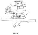
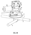
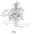
- FIGs. 1 a, 1 b and 2 there is shown two perspective views and a sectional view of part of an apparatus which is shown for the purposes of reference only with certain parts such as the housing, handle, battery, controls, lower shroud and wire spool removed for clarity.
- the apparatus is shown situated over a junction where two steel bars 2 cross over each other at right angles.
- the steel bars 2 are intended to form a rectangular grid to be embedded in a concrete structure in order to reinforce it.
- a domed shroud is provided around the lower end of the apparatus and has two part-circular depressions so that the apparatus can securely rest on the upper of the two bars 2 without slipping off.
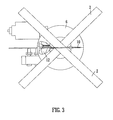
- the rotary head of the apparatus 4 This includes a horizontal circular base plate 6 extending up from which is a channel 8 which is approximately semi-circular in vertical section and of approximately constant width in the orthogonal direction. In the centre of base plate 6 is a part-spherical depression 9. The underneath of the base plate 6 is shown in Fig. 3 from which it will be seen that on one side there is a narrow slot 10 corresponding to one end of the semi-circular channel and on the other side of the plate 6 corresponding to the other end of the channel is a funnel region 12.
- the upper cylindrical portion of the head 14 which is rotatably mounted in the cylindrical portion 16a of a bracket member mounted to the housing (not shown) by a flange portion 16b (omitted from Fig. 1b ).
- the upper head portion is supported by two rotary bearings 18.
- a toothed gear wheel, 20 is provided fixed at the top of the head to allow it to be driven by a motor 22 via a worm gear.
- a solenoid assembly comprising a cylindrical outer tube 26 housing the coil and an inner plunger 28 which is able to slide vertically relative to the coil 26.
- an actuating disc 30 At the bottom end of the plunger 28 is an actuating disc 30, the purpose of which will be explained later.
- a pivotally mounted angled clutch lever 32 On the left hand side as seen from Fig. 2 , there may be seen a pivotally mounted angled clutch lever 32.
- a pair of compression springs 36 act on the longer, upper arm of the lever 32 so as to bias the lever in an anti-clockwise direction in which the shorter, lower arm is pressed downwardly.
- any number of springs might be used.
- To the right of the clutch lever 32 are a series of roller wheels 38a,38b,38c the purpose of which will be explained below.
- a similar clutch lever is provided displaced approximately 180 degrees around the head. This is not therefore visible in the sectional view.
- a wire feed inlet guide 40 which receives the free end of wire 46 which has been unwound from the spool (not shown).
- FIG 4 is a partly-schematic view of the apparatus in which the lower shroud 42 is shown. At two opposed points just inside the edge of the shroud 42 are disposed a pair of Hall effect sensors 44 which protrude slightly from the shroud. However they could equally be flush or slightly recessed. A further two sensors are provided at 90 degrees to those shown so that whichever of the four possible rotational positions the apparatus is brought down onto a steel reinforcing bar 2, two of the Hall sensors will give a detectable electronic signal indicating the ferromagnetic nature of the steel.
- a pair of electrodes are arranged to contact the reinforcing bar when it is properly positioned, thereby completing an electrical circuit through the bar.
- the apparatus is first brought down onto the uppermost of a pair of steel reinforcing bars 2 which are crossed at right angles.
- the shroud 42 When the shroud 42 is properly resting on the bar 2, the presence of the steel will be sensed by the two Hall effect sensors 44 which will allow the tying operation to be commenced. If the operator should attempt to commence the tying operation before both Hall effect sensors 44 sense the presence of the steel bar 2, a warning light such as an LED is illuminated and further operation of the apparatus is prevented.
- the sensing is carried out by detecting the completion of an electrical circuit though the bar. This shares the advantage that the sensing mechanism cannot be fooled by part of an operator's body such as a finger, or clothing etc.
- the operator may commence the tying operation.
- the first part of this operation is to energise the solenoid coil 26 which pushes the plunger member 28 downwardly.
- This causes the actuating member 30 at the end of the plunger to be pressed downwardly onto the upper arms of the clutch levers 32 to press them down against the respective compression springs 36 and therefore raise the shorter, lower arms. This is the position which is shown in Figure 2 .
- the main motor 22 is, if necessary, operated just long enough to rotate head 4 via the worm drive and gear wheel 24, 20 so that a channel for receiving the wire 46 is in correct alignment with the wire feed inlet guide 40. This is called the "park" position.
- the correct alignment may be detected simply by respective contacts provided on upper head portion 14 and the cylindrical housing 16a or wire inlet guide 40, although of course there are many other possibilities for this position detection.
- a separate motor (not shown) is operated to drive a wire feed roller (also not shown) that acts on the wire 46 to feed it from the spool through the wire inlet guide 40 and into the aligned channel in the upper head portion 14.
- the wire is fed in horizontally and encounters the first of the passive rollers 38a.
- the first roller 38a causes the wire to bend downwardly slightly so that it passes between the second and third rollers 38b, 38c.
- the relative positions of the three passive rollers 38a,38b,38c is such that when the wire 46 emerges from them it is bent so as to have an arcuate set.
- the wire 46 continues to be driven by the wire feed roller, it encounters and is guided by the inner surface of the semi-circular channel 8.
- the free end of the wire re-enters the semi-circular channel 8, it encounters the second clutch lever. This can be detected by sensing a slight displacement of the lever or by a separate sensor such as a micro switch, Hall effect sensor or other position detection means.
- the motor feeding the wire is stopped and therefore the wire does not advance any further.
- the solenoid coil 26 is then de-energised which causes the plunger 28 to be retracted by a spring (not shown) which releases the two clutch levers 32 so that their respective compression springs 36 act to press their lower arms against the two ends of the wire loop and therefore hold the wire 46 in place.
- the wire feed motor is driven in reverse in order to apply tension to the wire loop which draws the wire in around the reinforcing bars 2.
- This may be seen in Figure 6a .
- Figure 6b shows detail of the clutch lever 32 on the feed side clamping the end of the wire 46.
- a similar arrangement clamps the other end of the wire as explained above.
- the torque supplied by the motor 22 is sufficient to shear the wire at the point where it crosses from the inlet guide 40 to the upper head portion 14 without the need for it to be cut.
- an initial surge current e.g. boosted by a charge stored in a capacitor
- the head 4 begins to twist the sides of the loop together above the reinforcing bars 2.
- the first one or two turns of the head are the most important in ensuring a tight binding. As will be appreciated, these initial twists are carried out under tension and therefore a very tight binding is achieved. As twisting continues, each successive turn is less important for providing a tight binding. As twisting continues the tension in the wire will increase. However, the shape of the rounded ends 32a of the clutch levers that bear against the ends of the wire mean that as the wire is pulled passed it, it will tend to be pulled slightly anti-clockwise (looking at the lever shown in Fig. 6a ) and so increase the friction on the wire. This arrangement acts as an effective self-regulating mechanism to ensure that the wire can be drawn out by a measured amount. Since the area of mutual contact between the clutch lever 32 and the wire 46 is relatively small, effectively a point contact, the resistance force is less dependent on the co-efficient of friction than in prior art arrangements.
- the apparatus determines that a malfunction has taken place and so stops the wire feed motor and then carries out the wire cutting operation described above by applying a surge current to the main motor 22.
- the head 4 is returned to the "park" position and a further solenoid is energised to project a pin from the cylindrical bracket housing 16a into the upper head portion 14 to prevent further rotation until the fault has been rectified and this rotation lock has been manually reset by a user.
- a warning signal is given to a user e.g. by illuminating a red LED.
- the main solenoid 26 is de-activated again.
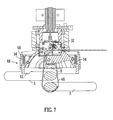
- FIG. 7 An embodiment of the invention is shown in Figure 7 .
- the apparatus is broadly the same as the previously described apparatus except that it has a different lower shroud 48.
- the shroud 48 comprises a fixed portion 50 and a moveable sprung portion 52 mounted to the fixed portion by a series of circumferentially spaced compression springs 54.
- the lower sprung portion of the shroud 52 sits on the steel reinforcing bar 2 in use of the device.
- the combined force of the compression springs 54 is sufficient to bear not only the weight of the apparatus, but the initial tension applied to the wire 46 before twisting is commenced which is the stage depicted in Fig. 7 .
- FIG. 8 A further embodiment is shown in Fig. 8 .
- a set of rollers 138 impart an arcuate set to the wire 146 as it leaves the head.
- Wire containment means in the form of a pair of curved support members 160 extend down from a shroud 142 around the head so as to straddle the junction between the two bars being tied (not shown).
- the wire 146 advances around towards the receiving means it is guided by its arcuate set and does not even touch the support members 160.
- the end of the wire 146 encounters resistance at the receiving means, rather than advancing further the diameter of the loop will increase as more wire is paid out by the head wire-issuing mechanism. After a short time though the wire loop grows into the support members which constrain it, preventing further growth. This again allows the loop to transmit the paying-out force to the end in order to overcome the resistance at the receiving end.
- the shape and exact location of the support members 160 is not critical and they may be made more robust and tolerant of damage than delicate jaws required to guide the wire.
- FIG. 9 to 13 A further embodiment of the invention is shown in Figs. 9 to 13 . This embodiment shares many characteristics with the apparatus previously described and the common features will not be described again in detail.
- Figs. 9 to 13 An important difference exhibited by the embodiment of Figs. 9 to 13 is that the rotatable head 204 is significantly smaller in diameter than in the previous embodiments. This can be seen by comparing the rotating head as shown in Fig. 12 with Fig.1b which shows the rotating parts 6, 8, 14, 18, 20 of the first embodiment.
- the base plate 6 and semi-circular channel 8 are both as wide as the loop of wire issued and rotate at this diameter.
- the wire 46 is issued into one of the wire guides 260a, 260b which do not rotate; it is not guided out to its maximum diameter by the head.
- the rotating head having the diameter D1 of the initial wire loop it has the much smaller diameter D2. This allows the overall size of the machine including housing etc. (not shown here to be much smaller and lighter). It also reduces the torque required of the motor further enhancing the size and weight benefits.
- the head 204 is open to the side in the region of the wire issuing means (rollers 238 etc.) but is closed off at the bottom by a tying plate 270.
- the tying plate is circular with two generally radial slots 272, 274, which extend to the edge of the plate. Each slot has a 'double-back' portion 272a, 272b at its radially innermost end which helps to prevent the wire slipping back out along the slot once it has passed along it.
- a domed depression 209 for turning down the ends of the wire as previously described.
- Fig. 9 shows the state of the machine immediately before a tying operation is commenced.
- the guide 260a on the wire issuing side has a length of wire 46 already received in it.
- the wire 46 begins immediately to cross the gap between the channels 260, under the reinforcing bars 2, and return back towards the receiving mechanism (clutch etc., not shown) on the other side of the head 204 to the issuing rollers 238). This is shown in Figs. 11 and 12 .
- the wire 46 does not pass through the tie plate 270.
- the wire 46 starts at the bottom end of the guide member 260a rather than where it first enters the head 204 from the spool (not shown), it has less distance to travel and the loop is completed more quickly - in approximately two thirds the time. This makes the overall tying operation quicker which is advantageous in terms of efficiency.
- the motor is stopped. This allows safe operator intervention without risking damage to the machine or the operator should the wire have become tangled.
- the wire is first retracted back to the position shown in Fig. 9 (i.e. the pre-feed position). In other embodiments however it could simply be left where it is for the operator to deal with, e.g. by cutting it manually; or automatically cut to allow it to be released by the operator.
- the wire travels around the inside surfaces of the guide members 260a, 260b and so in contrast to the containment channels 160, the guide members do provide some guiding function.
- the arcuate set on the wire is still significant as it allows the wire to pass through the open volume between the issuing part of the head 204 and the top end of the guide member 260a. This in turn enables the reduction in diameter of the head discussed.
- the set on the wire also obviates any need to provide a shuttle or the like to guide the wire across the gap between the guides 260a, 260b.
- the feed mechanism is reversed as described before to pull the wire taut around the bars 2.
- This causes the wire 46 to pass into the slots 272, 274 on either side of the tie plate until it is caught in the double-back portions 272a, 274a.
- the head 204 including the tie plate 270 is then rotated to twist the wire exactly as in the previous embodiments and apparatus.
- the feed motor is operated once again just long enough for the wire 46 to advance to the end of the first guide member 260a, i.e. to reach the situation shown in Fig. 9 . This can be carried out while the operator is moving the machine to the next tie site but reduces the time taken for the actual tying operation so allowing the overall work rate which can be achieved to increase.
- one of the wire feed rollers 238 does not have a smooth surface but rather has a circumferentially spaced series of teeth. By being of a harder material than the wire, this imparts the wire with a serrated surface texture which increases the grip which the receiving side clutch can apply to it. Since the serrated roller is disposed on one side of the wire only, only part of the circumference of the wire will be conditioned in this way. Of course many other types of conditioning could be applied e.g. smoothing or lubricating, or other sorts of roughening. Equally the conditioning could be applied at a different point in the machine or at several points.
- FIG. 14 A feature of a yet further embodiment of the invention is shown in Fig. 14 .
- the outer circumference of the rotary head 304 has an inclined notch 372 formed in it.
- a pin 374 is spring-mounted to a barrel 376 which is fixed to the body of the apparatus (not shown) and is arranged so as to be pressed into the notch 372 when they are rotationally aligned. When they are not aligned the pin 372 is forced back into the barrel 376 by the circumference of the head 304.
- variable force clamping mechanisms e.g. involving feedback of the tension in the wire; or indeed it may not be necessary to provide any such variable force mechanism.
Landscapes
- Engineering & Computer Science (AREA)
- Architecture (AREA)
- Mechanical Engineering (AREA)
- Civil Engineering (AREA)
- Structural Engineering (AREA)
- Basic Packing Technique (AREA)
- Hand Tools For Fitting Together And Separating, Or Other Hand Tools (AREA)
Description
- This invention relates to apparatus and methods for binding together objects using wire to tie them to each other. It relates particularly, although not exclusively, to binding together reinforcing bars which provide reinforcement to concrete structures.
- When building large concrete structures e.g. walls, floors, columns etc. in buildings, grids of reinforcing bars must typically be laid out and bound together on site before the concrete is poured over them. The reinforcing bars are laid out in a rectangular grid of horizontal and vertical bars. At selected intersections between horizontal and vertical bars, they are tied together using a loop of stiff wire which is passed diagonally under the intersection and the two ends of which are twisted together above the intersection in order to tie the two bars together. Traditionally this has been carried out manually although it is difficult, laborious and repetitive.
- There are available on the market some powered machines to carry out this task.
FR 2 552 364 A1WO 2004/083559 . Reference should be made to this document for full details although briefly the machine comprises a pair of claws which pass down either side of an intersection between two bars so that a wire can be passed (by means of a guide shuttle) across the gap between the tips of the claws and thereafter drawn up around the intersection and twisted together by means of a rotating spindle. - An improvement demonstrated by the machine disclosed in
WO 2004/083559 over prior arrangements is that the wire is allowed to be drawn out of the spindle during twisting by allowing some slippage against the grip on the wire. This helps to prevent the wire breaking under excess tension. - Although the improvements described in
WO 2004/083559 should be useful, the Applicant has appreciated that further improvement is possible. One problem which the Applicant has noticed is that it is common practice when in actual use on building sites to use the jaws of machines of the type described generally above, to knock flat the twisted ends of the wire once the twisting operation has been completed in order to prevent things snagging on the twisted wire which may have sharp ends. However, such machines are not designed for this purpose it has been observed that repeated knocks to the lower jaws from such use and other rough handling can quickly cause them to become distorted or misaligned. Since the jaws are essential for guiding the wire in the correct path, any such misalignment or distortion can prevent the machine operating properly. - Another potential problem identified by the Applicant is that achieving the proper tension in the twisted wire relies on the bending strength of the wire and friction exhibited between the wire and the gripping parts of the machine. However, if the surface of the wire or the interior gripping surface inside the machine should be contaminated with oil or grease, or indeed even if the machine is used in damp conditions, the degree of friction actually exhibited may be less than intended leading to a lower tension in the twisted wire and therefore a more loosely tied connection.
- The Applicant has further appreciated that an inherent problem with tying machines of the kind described is that since there must always be a region through which the wire passes which is essentially open, to allow the wire to pass around the bars, there might conceivably be an increased risk of injury to an operator or someone else if the wire tying action were initiated accidentally, for example when a part of the body was in the tying zone.
- It is an object of the present invention to provide at least some improvement on the aforementioned arrangements.
- When viewed from a first aspect the invention provides an apparatus for tying a wire around one or more objects comprising means for passing said wire in a loop around the objects and means for twisting the ends of said loop together, said twisting means comprising at least one gripping means for gripping the wire so that the wire does not slip therethrough, the apparatus comprising means for applying a biasing force between the twisting means and an object being tied such that as said wire is twisted the twisting means is drawn towards the object against said biasing force.
- Thus it will be seen that in accordance with the invention the ends of the wire are gripped sufficiently tightly to prevent the ends of the wire being pulled out during twisting but wherein the twisting mechanism is arranged to be drawn towards the object(s) being tied against a resilient bias force during twisting. This has the same effect of limiting the tension in the wire so that it is less prone to breaking under excess tension. Preferably said resilient biasing force is provided by a sprung housing, stand or frame which engages the object(s) being tied. Alternatively, the compressible portion of the apparatus may be provided elsewhere, e.g. between a frame or housing and the parts of the apparatus mounting the twisting mechanism.
- In one set of embodiments the apparatus comprises wire issuing and wire receiving means arranged to pass a wire imparted with an arcuate set in a loop around the objects from the issuing means to the receiving means.
- Thus it will be seen by those skilled in the art that in such embodiments, rather than the wire being guided around the objects to be tied with a pair of jaws, the apparatus relies on an arcuate set imparted to the wire to guide it around the objects to the receiving means. This is clearly advantageous as the alignment of the wire does not rely on the positions of jaws. The apparatus can therefore be made less prone to damage that prevents it working properly.
- The apparatus in accordance with the invention could be jaw-less. By jaw-less is meant that no part of it will project below the lowermost member being tied and indeed no part of it need project below either or any of the members to be tied together, so the whole operation can be carried out from above.
- If no jaws are provided the apparatus can be made extremely robustly. However it is not essential for it to be jaw-less. The Applicant has found that in some situations it is necessary or desirable to increase the force transmitted from the wire issuing means through the wire, for example to overcame resistance at the receiving means. As will be appreciated if the free end of the wire encounters too great a resistance, rather than advancing round, the wire loop grows in diameter. In accordance with some preferred embodiments of the invention, wire containment means are provided for restricting the growth in diameter of the wire loop. Such means allow a significantly greater force to be transmitted through the wire loop and thus make it easier to overcome any resistance encountered, e.g. at the receiving means.
- The wire containment means could simply be an extension of the shroud on one or both sides, a frame, or any other suitable structure for restricting enlargement of the loop. The wire containment means could even comprise one or more jaws. It will be appreciated however that in this example the jaw(s) are not relied upon to guide the wire accurately to the receiving means, the arcuate set achieves that, but rather to restrict enlargement of the loop. The construction of the jaw(s) may therefore be much simpler and the accurate positioning thereof is not essential in order to guide the wire. The benefits discussed above therefore still apply.
- The arcuate set which is imparted to the wire could simply be that which results from it being coiled around a spool for storage. However, this is possibly unreliable as spools may be of different sizes, wound to different tensions or unevenly; and the diameter of the set will reduce as the spool is consumed. Preferably, therefore, the apparatus comprises means for imparting the required arcuate set. This could comprise, for example, pinch rollers and/or a suitably curved guide surface or channel.
- The set applied to the wire is preferably substantially planar so that the free end of the wire tends to return towards the point from which it was issued; although in preferred embodiments the wire receiving means is arranged to guide the free end of the wire so as to have a slight lateral offset. This means that the issuing and receiving means may be laterally offset from one another which allows the device as a whole to be kept as compact as possible.
- The wire receiving means preferably comprises a funnelled surface to guide the free end of the wire into means for gripping it. The range over which the free end of the wire may strike the receiving means and still be properly guided to the gripping means will of course depend on the accuracy with which the wire loop is guided through the air by its pre-given set. Preferably the receiving surface is adapted to accommodate the free end of the wire landing within 10 cm of the gripping means in any direction, more preferably within 5 cm and more preferably within 1 cm.
- In some preferred embodiments the wire receiving means is adapted to detect when the free end of the wire has been received. Preferably the apparatus comprises means for determining if the wire has not been received correctly by the receiving means. For example such a determination could be made if the receiving means has not received the wire after a predetermined time; or after a predetermined number of revolutions of a feed mechanism; or any combination of these. Preferably the apparatus is configured to stop the wire feed if such a determination is made. Preferably it is also configured to release the wire as failure for the wire to be received normally indicates that it has become jammed or fouled. This could include cutting the wire to facilitate its removal.
- Preferably the apparatus comprises means for sensing the presence of a legitimate object to be tied in the zone through which the wire will pass. This enhances the safety of the apparatus by helping to ensure that the tying is only commenced in the correct circumstances. The sensing means could issue an alert if an appropriate object is not in the correct vicinity but preferably it simply prevents the tying action being initiated through a suitable controller.
- The sensing means could be configured to sense particular sizes or shapes corresponding to legitimate objects to be tied but preferably it senses the presence of an appropriate material for the object. For example, in the preferred embodiment in which the apparatus is adapted to tie concrete reinforcing bars together, the objects to be tied will be metal, more specifically steel. Preferably therefore the sensing means is arranged to sense the presence of metal, e.g. steel objects. In some embodiments the sensing means is arranged to sense the thermal, or preferably electrical, conductivity of the object. In other embodiments the sensing means is arranged to sense the presence of a material having a degree of ferromagnetism such as a steel bar. Any suitable magnetic sensor may be employed but preferably the sensing means in such embodiments comprises a Hall effect device. Detecting the presence of an object having the correct properties is advantageous insofar as it can discriminate a metal bar from e.g. a finger which simple contact sensors (e.g. micro-switches) cannot.
- The Applicants have also devised further improvements over the device described in
WO 2004/083559 . In accordance with preferred embodiments of the invention there is provided means for twisting the wire under tension said means being adapted to grip the wire with a variable gripping force so as in use to apply a substantially predetermined tension to the wire during at least a first tying phase. Thus in such embodiments the amount of grip is controlled to ensure that a desired amount of tension is applied to the wire during twisting. This helps to overcome the problems encountered in use of prior art devices in which the amount of grip could be influenced by uncontrolled external factors. - Any suitable means could be employed to give the described functionality but preferably the gripping means comprises one or more variable force clutch mechanisms. Preferably the apparatus comprises means for providing feedback of the amount of tension in the wire. This could, for example, be measured by monitoring current through a motor driving twisting means. Preferably however the or each clutch mechanism comprises a member resiliently biased onto the wire and shaped to increase the clamping force on the wire as the wire is drawn past it.
- The tension applied could be substantially constant throughout the twisting or could be varied, e.g. to reduce it after the first one or few turns. The Applicant has recognised that the most effective binding turns are the first one or two and therefore that a much lower tension may be used for subsequent turns without affecting the binding tightness. After the first few turns it has been recognised that subsequent twisting essentially simply tidies up the ends of the wire.
- It will be seen that the arrangements set out above are an improvement on the arrangement in
WO 2004/083559 where the degree of grip was not controlled. However, they share the principle of the wire being drawn out from the twisting mechanism by overcoming a resistance. - The Applicant has appreciated that the friction between the surface of the wire and the rollers, clutches and the like which interact with it is an important parameter. Furthermore it recognises that this can be affected by external factors. The previously mentioned variable force gripping means may be sufficient to accommodate the normally encountered range of friction coefficients. However in accordance with a further preferred feature of the invention, conditioning means are provided for altering the frictional properties of the surface of the wire. By being able to alter the frictional properties of the wire, the performance and reliability of the apparatus can be improved.
- The conditioning means could be arranged to reduce the friction presented by the wire - e.g. by smoothing, cleaning and/or lubricating the wire. Preferably however the conditioning means is arranged to increase the friction of the surface. This could be done by e.g. by coating the wire with a suitable material but preferably it is done by altering the texture of the surface - i.e. roughening it. In a preferred example the conditioning means comprises means for serrating the surface. Preferably the conditioning means comprises a suitable set of rollers, one or more of which have a surface adapted to impart the desired texture. The conditioning means could be independent of other mechanisms in the apparatus. Preferably however the conditioning means comprises a feed and/or bending roller which also performs another function in the operation of the apparatus.
- The surface conditioning could be applied around the whole circumference but in some preferred embodiments it is applied to part of the circumference only. This would allow it to be effective in some parts of the machine but not others depending on their circumferential orientation relative to the wire. Of course different conditioning could be applied to different parts of the circumference.
- In accordance with the invention it is normally necessary for the wire to be cut from a spool before twisting commences. This could be effected by a dedicated cutter. Preferably however the apparatus is configured to shear the wire as the twisting mechanism begins to turn. This is simpler and cheaper to manufacture than a dedicated cutter and associated controlling electronics. In some embodiments it could be arranged that more current is supplied to a motor at start-up to facilitate this.
- The Applicant has recognised the difficulties associated with dealing with the sharp ends that remain after the wire has been twisted. As explained previously, embodiments of the invention can be made much more robust than prior art machines and so will withstand better being used to knock over the wire after twisting. However it is still not desirable for the wire to require knocking over and in accordance with a further preferred feature the apparatus comprises a guiding surface arranged to deflect the wire as it is being twisted so that the ends of the wire finish pointing at least partially in the direction of the objects being tied, i.e. downwardly where the apparatus is used in the normal configuration vertically, above the objects. It has been found that in accordance with this feature there is no need to knock over the twisted potion of wire in order satisfactorily to reduce the risk of snagging - having the ends of the wire pointing downwardly can be sufficient for this.
- The guiding surface is preferably formed as a depression on part of the twisting means. The surface is therefore preferably rotationally symmetric and smoothly rounded to prevent catching. In preferred embodiments the guiding surface is part-spherical.
- At least preferred embodiments of the apparatus of the invention comprise a rotatable head arranged to rotate in order to twist the ends of the wire together. It could be arranged that the rotatable head comprises the guide guides the wire to its maximum diameter - i.e. that which is necessary to form a loop which passes around the intersecting reinforcing bars. Such an arrangement might be constructionally simple. However the Applicant has realised that the resulting diameter of the rotating head and hence the overall size of the lower part of the apparatus can be undesirably large in this case. In fact it has appreciated that because in accordance with preferred embodiments the ends of the wire are drawn together prior to rotation, the diameter of the head need only accommodate this smaller separation. Accordingly it is preferred that the rotatable head is smaller in diameter than the initial loop diameter. Where, as is preferred, the wire issuing means is provided on the rotatable head this means that the wire will move from he point at which it issues from the head as it is drawn in. Conveniently a slot is provided on the head to facilitate this.
- In preferred embodiments of the invention parking means are provided for returning the head to a predetermined 'parking' position or one of a plurality of predetermined parking positions. This is valuable as it ensures that the head is in the correct place for the next tying operation. Preferably the parking means is arranged to prevent the head from moving from said parking position in at least one direction. The parking means could comprise indexing or other position-determining means arranged to determine when the head is in a or the parking position so as to stop the motor and possibly engage a lock. For example a solenoid-operated latch or pin could be employed.
- In at least some preferred embodiments of the invention the parking means referred to above comprises a ratchet arrangement arranged to prevent rotation of the head in one direction beyond one or more predetermined points. Preferably the ratchet arrangement comprises a resiliently biased pawl acting on the head. The head could for example be provided with a suitable notch, stop or detent. Of course the pawl and ratchet surface could be reversed. Such ratchet arrangements are simple and reliable to implement and provide an automatic, physical, locking location of the head in a or the parking position when the head is rotated in the opposite direction to the normal twisting direction, in order to park it.
- In
WO 2004/083559 the wire is cut where it crosses from the stationary part of the apparatus into the rotatable head in order to allow the head to rotate. A fresh length of wire is fed into the rotatable head when the next tying operation is commenced. This sequence is perfectly logical. However the Applicant has appreciated that by altering this operation of the apparatus may be made more efficient. Preferably therefore the apparatus is arranged to pre-feed a length of wire beyond the cutting means at the end of a tying operation. By pre-feeding the wire at the end of the cutting operation, the subsequent tying operation can be carried out more quickly. Effectively this feature utilises the 'dead time' between tying operations which is required for the operator to move the machine to the next intersection requiring a tie. It has been found that in one example this can reduce the time for each tying operation by about 10 to 20 percent which is significant, particularly when multiplied across large numbers of operations. - The amount of wire that is pre-fed will depend to an extent on the construction of the apparatus. It is normally expected however that the wire will be pre-fed to an extent that it is not exposed from the apparatus. Of course it is necessary to ensure that the pre-fed wire does not interfere with locating the apparatus at the next reinforcing bar intersection.
- The precise point in the cycle at which the pre-feed occurs is not critical as long as it happens at some stage between completion of one tying operation and commencement of the next. Preferably it occurs after the or a rotatable head has been locked to prevent rotation.
- Certain preferred embodiments of the invention will now be described, by way of example only, with reference to the accompanying drawings in which:
-
Fig. 1 a is a perspective view of an apparatus shown for the purposes of reference only, without housings removed, above a pair of crossed bars prior to a tying operation being initiated; -
Fig. 1 b , shown for the purposes of reference only, is a view similar toFig. 1 a with the main mounting bracket removed; -
Fig. 2 , shown for the purposes of reference only, is a sectional view through the apparatus shown inFig. 1 ; -
Fig. 3 , shown for the purposes of reference only, is a view of the apparatus from beneath; -
Fig. 4 , shown for the purposes of reference only, is a partly schematic sectional view of the apparatus showing the lower shroud; -
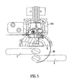
Fig. 5 , shown for the purposes of reference only, is a sectional view similar toFig. 2 showing the apparatus part-way through a tying operation; -
Fig. 6a , shown for the purposes of reference only, is another sectional view showing the wire tensioned prior to twisting; -
Fig. 6b , shown for the purposes of reference only, is an enlargement of the circled part ofFig. 6a ; -
Fig. 7 is a sectional view of an embodiment of the invention which has a sprung shroud; -
Fig. 8 is a schematic view of the lower part of a further apparatus in accordance with some embodiments of the invention set out herein; -
Fig. 9 is a cross-sectional view of a further embodiment of the invention prior to commencement of a tying operation; -
Fig. 10 is a bottom elevation of the apparatus ofFig. 9 ; -
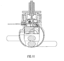
Fig. 11 is a view similar toFig. 9 during the tying operation; -
Fig. 12 is a perspective view corresponding toFig. 11 ; -
Fig. 13 is a cross-sectional view of the apparatus showing the wire immediately prior to twisting; and -
Fig. 14 is a partial sectional view of a further embodiment of the invention. - Referring first to
Figs. 1 a, 1 b and 2 there is shown two perspective views and a sectional view of part of an apparatus which is shown for the purposes of reference only with certain parts such as the housing, handle, battery, controls, lower shroud and wire spool removed for clarity. The apparatus is shown situated over a junction where twosteel bars 2 cross over each other at right angles. The steel bars 2 are intended to form a rectangular grid to be embedded in a concrete structure in order to reinforce it. Although not shown, a domed shroud is provided around the lower end of the apparatus and has two part-circular depressions so that the apparatus can securely rest on the upper of the twobars 2 without slipping off. - Sitting in use above the
uppermost bar 2 is the rotary head of theapparatus 4. This includes a horizontalcircular base plate 6 extending up from which is achannel 8 which is approximately semi-circular in vertical section and of approximately constant width in the orthogonal direction. In the centre ofbase plate 6 is a part-spherical depression 9. The underneath of thebase plate 6 is shown inFig. 3 from which it will be seen that on one side there is anarrow slot 10 corresponding to one end of the semi-circular channel and on the other side of theplate 6 corresponding to the other end of the channel is afunnel region 12. - Returning to
Figs. 1a ,1b and2 , attached to thesemi-circular channel 8 is the upper cylindrical portion of thehead 14 which is rotatably mounted in thecylindrical portion 16a of a bracket member mounted to the housing (not shown) by aflange portion 16b (omitted fromFig. 1b ). The upper head portion is supported by tworotary bearings 18. A toothed gear wheel, 20 is provided fixed at the top of the head to allow it to be driven by amotor 22 via a worm gear. - Extending through the
gear wheel 20 into the open upper end of thehead 4 is a solenoid assembly comprising a cylindricalouter tube 26 housing the coil and aninner plunger 28 which is able to slide vertically relative to thecoil 26. At the bottom end of theplunger 28 is anactuating disc 30, the purpose of which will be explained later. - The internal construction of the
head 4 will now be described. On the left hand side as seen fromFig. 2 , there may be seen a pivotally mounted angledclutch lever 32. A pair of compression springs 36 act on the longer, upper arm of thelever 32 so as to bias the lever in an anti-clockwise direction in which the shorter, lower arm is pressed downwardly. Of course any number of springs might be used. To the right of theclutch lever 32 are a series ofroller wheels 38a,38b,38c the purpose of which will be explained below. A similar clutch lever is provided displaced approximately 180 degrees around the head. This is not therefore visible in the sectional view. - To the left of the
upper head portion 14 connected to the mainbracket flange portion 16b is a wirefeed inlet guide 40 which receives the free end ofwire 46 which has been unwound from the spool (not shown). -
Figure 4 is a partly-schematic view of the apparatus in which thelower shroud 42 is shown. At two opposed points just inside the edge of theshroud 42 are disposed a pair ofHall effect sensors 44 which protrude slightly from the shroud. However they could equally be flush or slightly recessed. A further two sensors are provided at 90 degrees to those shown so that whichever of the four possible rotational positions the apparatus is brought down onto asteel reinforcing bar 2, two of the Hall sensors will give a detectable electronic signal indicating the ferromagnetic nature of the steel. - In an alternative arrangement (not shown) a pair of electrodes (one of which could be formed by part of the body or housing of the machine) are arranged to contact the reinforcing bar when it is properly positioned, thereby completing an electrical circuit through the bar.
- Operation of the apparatus will now be described. The apparatus is first brought down onto the uppermost of a pair of
steel reinforcing bars 2 which are crossed at right angles. When theshroud 42 is properly resting on thebar 2, the presence of the steel will be sensed by the twoHall effect sensors 44 which will allow the tying operation to be commenced. If the operator should attempt to commence the tying operation before bothHall effect sensors 44 sense the presence of thesteel bar 2, a warning light such as an LED is illuminated and further operation of the apparatus is prevented. - In the alternative arrangement referred to above the sensing is carried out by detecting the completion of an electrical circuit though the bar. This shares the advantage that the sensing mechanism cannot be fooled by part of an operator's body such as a finger, or clothing etc.
- Once the
steel bar 2 is properly sensed, the operator may commence the tying operation. The first part of this operation is to energise thesolenoid coil 26 which pushes theplunger member 28 downwardly. This causes the actuatingmember 30 at the end of the plunger to be pressed downwardly onto the upper arms of theclutch levers 32 to press them down against the respective compression springs 36 and therefore raise the shorter, lower arms. This is the position which is shown inFigure 2 . - Thereafter the
main motor 22 is, if necessary, operated just long enough to rotatehead 4 via the worm drive andgear wheel wire 46 is in correct alignment with the wirefeed inlet guide 40. This is called the "park" position. The correct alignment may be detected simply by respective contacts provided onupper head portion 14 and thecylindrical housing 16a orwire inlet guide 40, although of course there are many other possibilities for this position detection. - Once the
head 4 is in the "park" position, a separate motor (not shown) is operated to drive a wire feed roller (also not shown) that acts on thewire 46 to feed it from the spool through thewire inlet guide 40 and into the aligned channel in theupper head portion 14. The wire is fed in horizontally and encounters the first of thepassive rollers 38a. Thefirst roller 38a causes the wire to bend downwardly slightly so that it passes between the second and third rollers 38b, 38c. The relative positions of the threepassive rollers 38a,38b,38c is such that when thewire 46 emerges from them it is bent so as to have an arcuate set. As thewire 46 continues to be driven by the wire feed roller, it encounters and is guided by the inner surface of thesemi-circular channel 8. - When the
wire 46 emerges from thechannel 8, its arcuate set causes it to continue to describe an approximately circular arc, now unguided in free space, around the two reinforcing bars. This is shown inFigure 4 . As thewire 46 continues to be driven, the free end will eventually strike the mouth of thefunnel region 12 in the bottom of thebase plate 6 and therefore be guided back into thesemi-circular channel 8. However it is not guided back precisely diametrically opposite where it was issued from but rather slightly laterally offset therefrom. This allows the receiving means in the form of a further clutch lever (not shown) to be located next to the firstclutch lever 32 which enables the apparatus to be kept relatively compact. - It will be appreciated that since the
wire 46 describes a free, unguided circular path there is no need for any of the apparatus such as jaws to project below the reinforcingbars 2 to pass the wire around beneath them. - As the free end of the wire re-enters the
semi-circular channel 8, it encounters the second clutch lever. This can be detected by sensing a slight displacement of the lever or by a separate sensor such as a micro switch, Hall effect sensor or other position detection means. - Once the free end of the
wire 46 is detected, the motor feeding the wire is stopped and therefore the wire does not advance any further. At this point thesolenoid coil 26 is then de-energised which causes theplunger 28 to be retracted by a spring (not shown) which releases the twoclutch levers 32 so that their respective compression springs 36 act to press their lower arms against the two ends of the wire loop and therefore hold thewire 46 in place. - The wire feed motor is driven in reverse in order to apply tension to the wire loop which draws the wire in around the reinforcing bars 2. This may be seen in
Figure 6a .Figure 6b shows detail of theclutch lever 32 on the feed side clamping the end of thewire 46. A similar arrangement clamps the other end of the wire as explained above. When thewire 46 is fully tensioned it will be seen fromFig. 6a that the two ends of the loop are pulled up almost vertically from their initial circular profile. - As the
head 4 tries to start rotating at the beginning of the twisting operation the torque supplied by themotor 22 is sufficient to shear the wire at the point where it crosses from theinlet guide 40 to theupper head portion 14 without the need for it to be cut. If necessary an initial surge current (e.g. boosted by a charge stored in a capacitor) can be supplied to themotor 22 to deliver an initial spike in torque but this is not essential. With the wire thus broken, thehead 4 begins to twist the sides of the loop together above the reinforcing bars 2. - The first one or two turns of the head are the most important in ensuring a tight binding. As will be appreciated, these initial twists are carried out under tension and therefore a very tight binding is achieved. As twisting continues, each successive turn is less important for providing a tight binding. As twisting continues the tension in the wire will increase. However, the shape of the rounded ends 32a of the clutch levers that bear against the ends of the wire mean that as the wire is pulled passed it, it will tend to be pulled slightly anti-clockwise (looking at the lever shown in
Fig. 6a ) and so increase the friction on the wire. This arrangement acts as an effective self-regulating mechanism to ensure that the wire can be drawn out by a measured amount. Since the area of mutual contact between theclutch lever 32 and thewire 46 is relatively small, effectively a point contact, the resistance force is less dependent on the co-efficient of friction than in prior art arrangements. - When a satisfactorily twisted binding is achieved, which could be after just one turn or even less than a complete turn, the free ends of the wire simply need to be twisted together to reduce the risk of snagging they pose. This is achieved by releasing the ends of the wire by once again energising the
solenoid 26 to push theplunger 28 down and so disengage the lower faces 32a of the clutch levers from thewire 46. The remaining turns of the head are therefore carried out with the ends of the wire no longer clamped. The friction between the wire and the channel inside the head and the fact that the wire is required to bend as it is drawn out is sufficient to allow the rotary module to twist the ends. As sides of the loop are twisted together a stiff twisted section extends upwardly towards thebase plate 6 and is accommodated in thespherical depression 9 which deflects the twisted section down again. This means that when the ends of the wire emerge from the bottom of thehead 4, they will be pointing generally downwardly, i.e. towards thebars 2 rather than upwardly. The risk of snagging is therefore significantly reduced to the extent that the twisted section does not need to be manually knocked over to more the ends of the wire out of the way. - Once tying is completed the
solenoid 26 is de-energised, allowing theplunger 28 to retract and therefore releasing the clutch levers 32. By this time the ends of the wire will have passed through so the clutch levers no longer bear on the wire. Rotation of thehead 4 is stopped except to return it to the initial "park" position. A signal is then given to the operator that the tying operation has been successfully completed. This may, for example, involve illuminating a green LED or giving a beep. - If during the initial phase of operation where the
wire 46 is passed around thebars 2 the free end is not sensed on the receiving side, then after a predetermined time or a predetermined number of revolutions of the wire feed motor, the apparatus determines that a malfunction has taken place and so stops the wire feed motor and then carries out the wire cutting operation described above by applying a surge current to themain motor 22. After this thehead 4 is returned to the "park" position and a further solenoid is energised to project a pin from thecylindrical bracket housing 16a into theupper head portion 14 to prevent further rotation until the fault has been rectified and this rotation lock has been manually reset by a user. A warning signal is given to a user e.g. by illuminating a red LED. At the end of this operation themain solenoid 26 is de-activated again. - It will be seen from the foregoing description that a particularly advantageous apparatus for binding together two bars by tying a loop of wire around them is provided. In particular, since the wire initially executes a large, approximately circular, path around the two bars and is then drawn up under tension into a tight loop, the advantage is obtained of not requiring jaws or the like projecting below the two bars in order to guide the wire, whilst at the same time giving the advantage that vertical pre-tension is applied before twisting takes place which results in a tight binding.
- An embodiment of the invention is shown in
Figure 7 . In this embodiment the apparatus is broadly the same as the previously described apparatus except that it has a differentlower shroud 48. In particular, theshroud 48 comprises a fixedportion 50 and a moveable sprungportion 52 mounted to the fixed portion by a series of circumferentially spaced compression springs 54. As is shown inFig. 7 , the lower sprung portion of theshroud 52 sits on thesteel reinforcing bar 2 in use of the device. Furthermore, it may be seen that the combined force of the compression springs 54 is sufficient to bear not only the weight of the apparatus, but the initial tension applied to thewire 46 before twisting is commenced which is the stage depicted inFig. 7 . - However, as the wire is twisted through the first one or few turns, the increasing tension in the
wire 46 pulls the apparatus down towards the reinforcingbar 2 against the force of thesprings 54. This helps to limit the tension in the wire to prevent breakage. This embodiment is shown with the previously described clutch lever arrangements, although it will be appreciated that in view of the sprung shroud it may not be necessary to allow the wire to slip past the clutches. A different clamping mechanism might therefore be used. - When the wire is released by the
clutch levers 32 or other clamp mechanism, the restoring force of thesprings 54 pushes the apparatus back up and helps to draw the wire out of the device. - Once the ends of the wire have been twisted together, there will inevitably be two short end portions which are not fully twisted and therefore stick out and still prevent a risk of snagging. It is therefore practice to bend the twisted part of the wire down so that the sharp ends of the wire no longer stick up but rather are angled downwards. Although this should be done manually, if an operator decides in practice to use the end of the device, it will be the
circular base plate 6 orshroud - A further embodiment is shown in
Fig. 8 . In this embodiment a set ofrollers 138 impart an arcuate set to thewire 146 as it leaves the head. Wire containment means in the form of a pair ofcurved support members 160 extend down from ashroud 142 around the head so as to straddle the junction between the two bars being tied (not shown). As thewire 146 advances around towards the receiving means it is guided by its arcuate set and does not even touch thesupport members 160. However if when the end of thewire 146 encounters resistance at the receiving means, rather than advancing further the diameter of the loop will increase as more wire is paid out by the head wire-issuing mechanism. After a short time though the wire loop grows into the support members which constrain it, preventing further growth. This again allows the loop to transmit the paying-out force to the end in order to overcome the resistance at the receiving end. - It will be seen that the shape and exact location of the
support members 160 is not critical and they may be made more robust and tolerant of damage than delicate jaws required to guide the wire. - A further embodiment of the invention is shown in
Figs. 9 to 13 . This embodiment shares many characteristics with the apparatus previously described and the common features will not be described again in detail. - An important difference exhibited by the embodiment of
Figs. 9 to 13 is that therotatable head 204 is significantly smaller in diameter than in the previous embodiments. This can be seen by comparing the rotating head as shown inFig. 12 withFig.1b which shows therotating parts Fig. 1 b thebase plate 6 andsemi-circular channel 8 are both as wide as the loop of wire issued and rotate at this diameter. In the embodiment ofFigs. 9 to 13 thewire 46 is issued into one of the wire guides 260a, 260b which do not rotate; it is not guided out to its maximum diameter by the head. Thus rather than the rotating head having the diameter D1 of the initial wire loop it has the much smaller diameter D2. This allows the overall size of the machine including housing etc. (not shown here to be much smaller and lighter). It also reduces the torque required of the motor further enhancing the size and weight benefits. - The
head 204 is open to the side in the region of the wire issuing means (rollers 238 etc.) but is closed off at the bottom by a tyingplate 270. This is seen most clearly in the view from beneath ofFig. 10 . The tying plate is circular with two generallyradial slots domed depression 209 for turning down the ends of the wire as previously described. -
Fig. 9 shows the state of the machine immediately before a tying operation is commenced. In this state theguide 260a on the wire issuing side has a length ofwire 46 already received in it. Thus when the tying operation is commenced thewire 46 begins immediately to cross the gap between the channels 260, under the reinforcingbars 2, and return back towards the receiving mechanism (clutch etc., not shown) on the other side of thehead 204 to the issuing rollers 238). This is shown inFigs. 11 and12 . During this phase of the tying operation thewire 46 does not pass through thetie plate 270. - As the wire advances it travels along the inside of the
other guide member 260b until it is received and gripped by the receiving side rollers and clamped by the clutch member (also not shown) as previously described. However because thewire 46 starts at the bottom end of theguide member 260a rather than where it first enters thehead 204 from the spool (not shown), it has less distance to travel and the loop is completed more quickly - in approximately two thirds the time. This makes the overall tying operation quicker which is advantageous in terms of efficiency. - As before if the end of the wire should not have been received after a predetermined time or number of revolutions of the feed motor the motor is stopped. This allows safe operator intervention without risking damage to the machine or the operator should the wire have become tangled. In the embodiment described herein the wire is first retracted back to the position shown in
Fig. 9 (i.e. the pre-feed position). In other embodiments however it could simply be left where it is for the operator to deal with, e.g. by cutting it manually; or automatically cut to allow it to be released by the operator. - In this embodiment the wire travels around the inside surfaces of the
guide members containment channels 160, the guide members do provide some guiding function. However the arcuate set on the wire is still significant as it allows the wire to pass through the open volume between the issuing part of thehead 204 and the top end of theguide member 260a. This in turn enables the reduction in diameter of the head discussed. The set on the wire also obviates any need to provide a shuttle or the like to guide the wire across the gap between theguides - Once the wire is clamped at the receiving end the feed mechanism is reversed as described before to pull the wire taut around the
bars 2. This causes thewire 46 to pass into theslots head 204 including thetie plate 270 is then rotated to twist the wire exactly as in the previous embodiments and apparatus. After the tying operation is completed however, and thehead 204 has been returned to its 'park' position, the feed motor is operated once again just long enough for thewire 46 to advance to the end of thefirst guide member 260a, i.e. to reach the situation shown inFig. 9 . This can be carried out while the operator is moving the machine to the next tie site but reduces the time taken for the actual tying operation so allowing the overall work rate which can be achieved to increase. - Although not visible in the Figures, one of the
wire feed rollers 238 does not have a smooth surface but rather has a circumferentially spaced series of teeth. By being of a harder material than the wire, this imparts the wire with a serrated surface texture which increases the grip which the receiving side clutch can apply to it. Since the serrated roller is disposed on one side of the wire only, only part of the circumference of the wire will be conditioned in this way. Of course many other types of conditioning could be applied e.g. smoothing or lubricating, or other sorts of roughening. Equally the conditioning could be applied at a different point in the machine or at several points. - A feature of a yet further embodiment of the invention is shown in
Fig. 14 . In this embodiment the outer circumference of therotary head 304 has aninclined notch 372 formed in it. Apin 374 is spring-mounted to abarrel 376 which is fixed to the body of the apparatus (not shown) and is arranged so as to be pressed into thenotch 372 when they are rotationally aligned. When they are not aligned thepin 372 is forced back into thebarrel 376 by the circumference of thehead 304. This gives a ratchet arrangement in which thehead 304 can rotate freely in an anti-clockwise direction (as viewed fromFig. 14 ) but cannot rotate in the clockwise direction beyond the point at which thepin 374 is aligned with thenotch 372 in the head. The head can thus be rotated anti-clockwise to twist the wire as previously described; and then the rotation reversed to return the head to the park position shown inFig. 14 . Of course there could be more than one park position depending on the symmetry of the head, in which case there would be corresponding multiple notches (and/or pins). This ratchet arrangement has the advantage of being a simple and reliable way of parking the head. - It will be appreciated by those skilled in the art that only certain specific embodiments of the invention have been described and that many variations and modifications are possible within the scope of the invention. For example, it is not essential to employ the resiliently biased clutch mechanisms described but rather other variable force clamping mechanisms might be envisaged e.g. involving feedback of the tension in the wire; or indeed it may not be necessary to provide any such variable force mechanism.
- Although the invention has been described in the context of tying a loop of wire around a crossed pair of steel concrete reinforcing bars, apparatus according to the invention may be used in other applications and for example it is not essential that two items are bound together, it may be that a wire is tied onto a single item. Equally, although Hall sensors have been described for detecting the presence of a bar prior to tying, many other ways of achieving this may be envisaged.
Claims (13)
- An apparatus for tying a wire (46) around one or more objects (2) comprising means (38a, 38b, 38c, 8) for passing said wire (46) in a loop around the objects (2) and means (4) for twisting the ends of said loop together, said twisting means (4) comprising at least one gripping means (32, 32a, 36) for gripping the wire (46) so that the wire (46) does not slip therethrough characterised in that the apparatus comprises means (52, 54) for applying a biasing force between the twisting means (4) and an object (2) being tied such that as said wire (46) is twisted the twisting means (4) is drawn towards the object (2) against said biasing force.
- An apparatus as claimed in claim 1, wherein said resilient biasing force is provided by a sprung housing, stand or frame (52) which engages the object(s) (2) being tied.
- An apparatus as claimed in claim 1 or 2, comprising conditioning means (238) for altering the frictional properties of the surface of the wire (46).
- An apparatus as claimed in claim 3, wherein said conditioning means (238) is adapted to increase the friction of the surface by altering the texture of the surface.
- An apparatus as claimed in claim 4, wherein the conditioning means (238) comprises means for serrating the surface.
- An apparatus as claimed in claim 3, 4 or 5, wherein the conditioning means (238) comprises a set of rollers, one or more of which has a surface adapted to impart said texture.
- An apparatus as claimed in any preceding claim wherein said twisting means comprises a rotatable head (4) arranged to rotate in order to twist the ends of the wire (46) together.
- An apparatus as claimed in claim 7 comprising wire issuing means (40, 8) provided on the rotatable head (4).
- Apparatus as claimed in claim 7 or 8 comprising parking means for returning the head to a predetermined parking position or one of a plurality of predetermined parking positions.
- An apparatus as claimed in any preceding claim which is configured to shear the wire (46) as the twisting means (4) begins to turn.
- An apparatus as claimed in any preceding claim comprising a guiding surface (9) arranged to deflect the wire (46) as it is being twisted so that the ends of the wire finish pointing at least partially in the direction of the objects (2) being tied.
- An apparatus as claimed in any preceding claim comprising means for cutting (14, 22, 40) the wire (46) and arranged to pre-feed a length of wire (46) beyond the cutting means (14, 22, 40) at the end of a tying operation.
- An apparatus as claimed in any preceding claim comprising wire issuing (40, 8) and wire receiving means (12) arranged to pass a wire (46) imparted with an arcuate set in a loop around the objects (2) from the issuing means (40, 8) to the receiving means (12).
Applications Claiming Priority (4)
| Application Number | Priority Date | Filing Date | Title |
|---|---|---|---|
| GB0520523A GB0520523D0 (en) | 2005-10-10 | 2005-10-10 | Object binding |
| GB0520934A GB0520934D0 (en) | 2005-10-14 | 2005-10-14 | Object binding |
| GB0525885A GB0525885D0 (en) | 2005-12-20 | 2005-12-20 | Object binding |
| EP06794700.2A EP1951973B1 (en) | 2005-10-10 | 2006-10-09 | Apparatus for binding objects together |
Related Parent Applications (3)
| Application Number | Title | Priority Date | Filing Date |
|---|---|---|---|
| EP06794700.2A Division EP1951973B1 (en) | 2005-10-10 | 2006-10-09 | Apparatus for binding objects together |
| EP06794700.2A Division-Into EP1951973B1 (en) | 2005-10-10 | 2006-10-09 | Apparatus for binding objects together |
| EP06794700.2 Division | 2006-10-09 |
Publications (2)
| Publication Number | Publication Date |
|---|---|
| EP2666932A1 EP2666932A1 (en) | 2013-11-27 |
| EP2666932B1 true EP2666932B1 (en) | 2016-07-20 |
Family
ID=37462394
Family Applications (2)
| Application Number | Title | Priority Date | Filing Date |
|---|---|---|---|
| EP06794700.2A Active EP1951973B1 (en) | 2005-10-10 | 2006-10-09 | Apparatus for binding objects together |
| EP13176935.8A Not-in-force EP2666932B1 (en) | 2005-10-10 | 2006-10-09 | Object binding |
Family Applications Before (1)
| Application Number | Title | Priority Date | Filing Date |
|---|---|---|---|
| EP06794700.2A Active EP1951973B1 (en) | 2005-10-10 | 2006-10-09 | Apparatus for binding objects together |
Country Status (7)
| Country | Link |
|---|---|
| US (3) | US9593496B2 (en) |
| EP (2) | EP1951973B1 (en) |
| CN (2) | CN105386602B (en) |
| AU (1) | AU2006301032A1 (en) |
| BR (1) | BRPI0617434A2 (en) |
| CA (1) | CA2625483A1 (en) |
| WO (1) | WO2007042785A2 (en) |
Cited By (1)
| Publication number | Priority date | Publication date | Assignee | Title |
|---|---|---|---|---|
| WO2021086253A1 (en) | 2019-10-28 | 2021-05-06 | Husqvarna Ab | Rebar tying device comprising a wire locking mechanism and a control unit for controlling the wire locking mechanism |
Families Citing this family (34)
| Publication number | Priority date | Publication date | Assignee | Title |
|---|---|---|---|---|
| CN105386602B (en) | 2005-10-10 | 2019-05-17 | 胡斯华纳有限公司 | For by binding objects to equipment together |
| JP5126101B2 (en) * | 2008-05-19 | 2013-01-23 | マックス株式会社 | Rebar binding machine |
| TWI516415B (en) | 2008-12-12 | 2016-01-11 | 美克司股份有限公司 | Reinforcing bar binding machine |
| GB0902179D0 (en) * | 2009-02-10 | 2009-03-25 | Tymatic Ltd | Machine for binding reinforcement bars |
| GB0906575D0 (en) | 2009-04-16 | 2009-05-20 | Tymatic Ltd | Wire binding machines |
| GB0908106D0 (en) * | 2009-05-11 | 2009-06-24 | Tymatic Ltd | Machine for binding reinforcement bars |
| GB0908105D0 (en) * | 2009-05-11 | 2009-06-24 | Tymatic Ltd | Machine for binding reinforcemnet bars |
| US9272799B2 (en) | 2011-10-04 | 2016-03-01 | Signode Industrial Group Llc | Sealing tool for strap |
| US9719331B2 (en) | 2012-05-13 | 2017-08-01 | Alexander H. Slocum | Method and apparatus for bringing under control an uncontrolled flow through a flow device |
| DE102012216831A1 (en) | 2012-09-19 | 2014-03-20 | Wobben Properties Gmbh | Device and method for automatic twisting of metal wires, in particular for connecting adjacent, preferably crossing structural elements |
| CN103726663B (en) * | 2013-11-25 | 2015-12-09 | 成都市翻鑫家科技有限公司 | New steel binding hook |
| JP6417772B2 (en) * | 2014-07-31 | 2018-11-07 | マックス株式会社 | Rebar binding machine |
| JP6471432B2 (en) * | 2014-09-03 | 2019-02-20 | 株式会社大林組 | Reinforcing bar binding device and reinforcing bar binding method |
| JP6473394B2 (en) * | 2015-07-13 | 2019-02-20 | 株式会社マキタ | Reinforcing bar binding device |
| US10486645B2 (en) * | 2015-11-20 | 2019-11-26 | Ford Global Technologies, Llc | Lock for vehicle active front steering system |
| US10577137B2 (en) | 2015-12-09 | 2020-03-03 | Signode Industrial Group Llc | Electrically powered combination hand-held notch-type strapping tool |
| SE539617C2 (en) * | 2016-02-12 | 2017-10-17 | Construction Tools Pc Ab | Knot plate for a sewing machine and a sewing machine comprising the knot plate |
| CN106143984B (en) * | 2016-08-29 | 2018-07-31 | 山东吉威医疗制品有限公司 | A kind of metallic support bind hider |
| SE540858C2 (en) * | 2017-04-06 | 2018-12-04 | Husqvarna Ab | Apparatus for controlling a thread in a sewing machine and a sewing machine comprising the apparatus and a sewing process |
| CN108868158B (en) * | 2018-07-27 | 2020-10-30 | 中交一公局重庆城市建设发展有限公司 | Method for positioning assembled building steel bars |
| EP3848292B1 (en) * | 2018-09-07 | 2024-01-31 | Max Co., Ltd. | Binding machine |
| JP7163679B2 (en) * | 2018-09-07 | 2022-11-01 | マックス株式会社 | binding machine |
| JP7379941B2 (en) * | 2018-09-07 | 2023-11-15 | マックス株式会社 | tying machine |
| NZ773631A (en) * | 2018-09-07 | 2026-03-27 | Max Co Ltd | Binding machine |
| JP7275506B2 (en) | 2018-09-07 | 2023-05-18 | マックス株式会社 | binding machine |
| US11174051B2 (en) | 2019-02-15 | 2021-11-16 | Samuel, Son & Co. (Usa) Inc. | Hand held strapping tool |
| JP7319849B2 (en) * | 2019-07-05 | 2023-08-02 | 株式会社マキタ | Reinforcing bar binding machine and binding method using the same |
| CN111236658B (en) * | 2020-03-28 | 2020-12-15 | 重庆吉禾建筑工程有限公司 | Iron wire binding device for building |
| IT202000021862A1 (en) | 2020-09-16 | 2022-03-16 | Schnell Spa | METHOD AND EQUIPMENT FOR BINDING METAL WIRE AND SIMILAR PRODUCTS |
| CN112343348B (en) * | 2020-10-27 | 2021-11-30 | 雷磊 | Angle connecting device for reinforcing steel bars |
| JP7771550B2 (en) * | 2021-07-30 | 2025-11-18 | マックス株式会社 | tying machine |
| JP7790082B2 (en) * | 2021-10-20 | 2025-12-23 | マックス株式会社 | Binding machine |
| US12397943B2 (en) | 2022-11-29 | 2025-08-26 | Samuel, Son & Co. (Usa) Inc. | Handheld strapping device |
| SE546542C2 (en) | 2022-12-15 | 2024-11-26 | Husqvarna Ab | A rebar wire tying device with blank fire reset function |
Family Cites Families (50)
| Publication number | Priority date | Publication date | Assignee | Title |
|---|---|---|---|---|
| US1809566A (en) | 1928-05-10 | 1931-06-09 | Acme Steel Co | Gripping dog |
| US2919894A (en) | 1955-10-19 | 1960-01-05 | Sharon Steel Corp | Strap stretching tool construction |
| US3028885A (en) | 1958-06-02 | 1962-04-10 | Signode Steel Strapping Co | Power strap tensioning tool |
| US3169559A (en) * | 1961-03-02 | 1965-02-16 | Jr Loren F Working | Wire tying tool |
| DE1215142B (en) * | 1964-07-09 | 1966-04-28 | Bayer Ag | Process for the preparation of araliphatic isonitriles |
| FR1576602A (en) | 1968-06-12 | 1969-08-01 | ||
| US3632969A (en) | 1969-05-08 | 1972-01-04 | Texas Instruments Inc | Electronic printhead protection |
| US3632959A (en) | 1970-06-15 | 1972-01-04 | Crc Crose Int Inc | Exchangeable cartridge unit for automatic welders |
| US3718798A (en) | 1971-06-21 | 1973-02-27 | Crc Crose Int Inc | Traveling welding apparatus |
| AT349861B (en) | 1976-05-25 | 1979-04-25 | Evg Entwicklung Verwert Ges | BINDING TOOL FOR TWISTING THE FREE ENDS OF A BINDING WIRE AND LATTICE TYING MACHINE WITH SUCH TOOLS |
| DE2804300A1 (en) * | 1978-02-01 | 1979-08-02 | Adolf Runkel | Reinforcing bars connection in concrete - involves wire forwarded to form loop with ends twisted to grip bars |
| FR2491527A1 (en) | 1980-10-07 | 1982-04-09 | Lafon Guy | PORTABLE MACHINE FOR AUTOMATICALLY REALIZING LIGATURES ON ARMATURE ARMATURES AND METHOD OF OPERATION |
| US4362192A (en) * | 1981-03-05 | 1982-12-07 | Furlong Donn B | Wire tying power tool |
| FR2502582A1 (en) | 1981-03-26 | 1982-10-01 | Grenon Rene | TWISTING SYSTEM FOR METALLIC WIRES |
| DE3419596A1 (en) * | 1983-05-30 | 1984-12-06 | Adolf 5630 Remscheid Runkel | Method for connecting two intersecting rods and an apparatus for carrying out the method |
| FR2552364B1 (en) * | 1983-09-23 | 1985-12-20 | Lafon Guy | DEVICE FOR PERFORMING LIGATIONS, ESPECIALLY WITH A METAL WIRE |
| US4655264A (en) | 1983-10-27 | 1987-04-07 | Ben Clements & Sons, Inc. | Twist tying machine |
| CH648085A5 (en) | 1984-07-26 | 1985-02-28 | Gamper & Co Ag | Unit for twisting two straight wire ends |
| US5004020A (en) | 1988-01-21 | 1991-04-02 | Newtech Products, Inc. | Wire twisting apparatus |
| US4953598A (en) | 1989-04-13 | 1990-09-04 | Mccavey William M | Wire tying tool for concrete reinforcing steel |
| US5368278A (en) * | 1989-11-15 | 1994-11-29 | Paul Hellermann Gmbh | Appliance and process for tying an article, especially a cable harness |
| CN2072470U (en) * | 1990-06-26 | 1991-03-06 | 黄确亮 | Tie wire clamp |
| SE9003176D0 (en) * | 1990-10-04 | 1990-10-04 | Peter Hoyaukin | SEAT AND MACHINE CONNECTING CROSSING RODS |
| JPH06502127A (en) * | 1991-08-02 | 1994-03-10 | ゲイトウェイ コンストラクション カンパニー、インコーポレイテッド | hardcore binding power tools |
| ES2057996B1 (en) | 1991-11-29 | 1995-10-16 | Tecnologia Del Automatismo S L | IMPROVEMENTS IN WINDING AND BINDING MACHINES |
| MY130074A (en) * | 1992-02-28 | 2007-05-31 | Bentac Co Ltd | Method and apparatus for tying one more articles |
| CA2192568A1 (en) | 1994-06-24 | 1996-01-04 | Graeme John Doyle | Wire tying tool with drive mechanism |
| DE69616761T2 (en) * | 1995-02-17 | 2002-08-01 | Japan Automatic Machine Co., Ltd. | METHOD AND DEVICE FOR STRAPPING OBJECTS |
| US5678613A (en) * | 1995-06-30 | 1997-10-21 | Max Co., Ltd. | Reinforcement binding machine |
| DE19528022C2 (en) | 1995-07-31 | 1999-02-11 | Bau Und Maschinenschlosserei F | Transportable device for connecting reinforcing bars |
| JP2923242B2 (en) * | 1996-03-15 | 1999-07-26 | 大木樹脂工業株式会社 | Rebar binding machine |
| US5826629A (en) * | 1997-01-17 | 1998-10-27 | John E. Burford | Pneumatic wire tying apparatus |
| US5778945A (en) | 1997-03-14 | 1998-07-14 | Tempel Steel Company, Inc. | Automatic wire twister |
| DE19806995C2 (en) * | 1998-02-19 | 2001-07-05 | Hunklinger Jun | Method and device for connecting objects using braided wire |
| US6041833A (en) | 1998-05-26 | 2000-03-28 | Suric; Marijan | Wire clamping and twisting device for use with cordless electric screwdriver |
| JP3010353B1 (en) | 1998-08-26 | 2000-02-21 | ジャパンライフ株式会社 | Reinforcing mesh binding machine |
| CN1122618C (en) * | 1999-04-28 | 2003-10-01 | 肖广勇 | Binder of reinforcing bars |
| US6401766B1 (en) * | 1999-07-23 | 2002-06-11 | Max Co., Ltd. | Binding machine for reinforcing bars |
| US6745677B2 (en) * | 2001-07-12 | 2004-06-08 | Illinois Tool Works, Inc. | Strapping machine with easy access and feed guides |
| AU2002318747B2 (en) * | 2001-07-19 | 2008-02-21 | Max Co., Ltd | Reinforcing steel bar tying machine |
| JP3624873B2 (en) | 2001-10-29 | 2005-03-02 | マックス株式会社 | Binding wire twisting device for reinforcing bar binding machine |
| JP3680804B2 (en) | 2002-03-12 | 2005-08-10 | マックス株式会社 | Rebar binding machine |
| JP2004142813A (en) | 2002-10-28 | 2004-05-20 | Max Co Ltd | Reinforcement bundler |
| SE0302276L (en) | 2003-03-18 | 2004-04-06 | Peter Hoyaukin | Method and machine for bonding elongated objects |
| CN2652552Y (en) * | 2003-10-17 | 2004-11-03 | 李国昌 | Rebar Binding Wire Binder |
| CN105386602B (en) | 2005-10-10 | 2019-05-17 | 胡斯华纳有限公司 | For by binding objects to equipment together |
| GB0520523D0 (en) * | 2005-10-10 | 2005-11-16 | Tymatic Ltd | Object binding |
| GB0906575D0 (en) | 2009-04-16 | 2009-05-20 | Tymatic Ltd | Wire binding machines |
| GB0908105D0 (en) | 2009-05-11 | 2009-06-24 | Tymatic Ltd | Machine for binding reinforcemnet bars |
| GB0908106D0 (en) | 2009-05-11 | 2009-06-24 | Tymatic Ltd | Machine for binding reinforcement bars |
-
2006
- 2006-10-09 CN CN201510673195.0A patent/CN105386602B/en active Active
- 2006-10-09 CA CA002625483A patent/CA2625483A1/en not_active Abandoned
- 2006-10-09 WO PCT/GB2006/003749 patent/WO2007042785A2/en not_active Ceased
- 2006-10-09 US US12/089,896 patent/US9593496B2/en active Active
- 2006-10-09 EP EP06794700.2A patent/EP1951973B1/en active Active
- 2006-10-09 CN CN201210111573.2A patent/CN102720366B/en active Active
- 2006-10-09 AU AU2006301032A patent/AU2006301032A1/en not_active Abandoned
- 2006-10-09 EP EP13176935.8A patent/EP2666932B1/en not_active Not-in-force
- 2006-10-09 BR BRPI0617434-5A patent/BRPI0617434A2/en active IP Right Grant
-
2017
- 2017-02-02 US US15/423,354 patent/US10240355B2/en not_active Expired - Fee Related
-
2019
- 2019-03-08 US US16/296,913 patent/US11473322B2/en active Active
Cited By (1)
| Publication number | Priority date | Publication date | Assignee | Title |
|---|---|---|---|---|
| WO2021086253A1 (en) | 2019-10-28 | 2021-05-06 | Husqvarna Ab | Rebar tying device comprising a wire locking mechanism and a control unit for controlling the wire locking mechanism |
Also Published As
| Publication number | Publication date |
|---|---|
| CN105386602B (en) | 2019-05-17 |
| US11473322B2 (en) | 2022-10-18 |
| CA2625483A1 (en) | 2007-04-19 |
| US20110155277A1 (en) | 2011-06-30 |
| AU2006301032A1 (en) | 2007-04-19 |
| EP2666932A1 (en) | 2013-11-27 |
| CN102720366B (en) | 2016-04-06 |
| CN105386602A (en) | 2016-03-09 |
| US10240355B2 (en) | 2019-03-26 |
| BRPI0617434A2 (en) | 2011-07-26 |
| US20170145704A1 (en) | 2017-05-25 |
| US20190203486A1 (en) | 2019-07-04 |
| CN102720366A (en) | 2012-10-10 |
| WO2007042785A2 (en) | 2007-04-19 |
| US9593496B2 (en) | 2017-03-14 |
| WO2007042785A3 (en) | 2007-08-02 |
| EP1951973A2 (en) | 2008-08-06 |
| EP1951973B1 (en) | 2014-12-10 |
Similar Documents
| Publication | Publication Date | Title |
|---|---|---|
| US11473322B2 (en) | Apparatus for tying wire around one or more objects | |
| CA3014611C (en) | Reinforcing bar binding machine | |
| EP2419582B1 (en) | Wire binding machines | |
| JP7647845B2 (en) | Binding machine | |
| WO2008062213A2 (en) | Wire tying machines | |
| CN101300395A (en) | Apparatus for binding articles together | |
| US20120132088A1 (en) | Machine for binding reinforcement bars | |
| EP2078125B1 (en) | Wire tying machines | |
| RU2429100C2 (en) | Device for items binding | |
| BRPI0617434B1 (en) | APPARATUS TO TIE A WIRE | |
| SE527781C2 (en) | Binding machine for elongated objects, e.g. concrete reinforcing bars, has claws for guiding wire to form bracket around three sides of objects and device for bending bracket arms towards objects |
Legal Events
| Date | Code | Title | Description |
|---|---|---|---|
| PUAI | Public reference made under article 153(3) epc to a published international application that has entered the european phase |
Free format text: ORIGINAL CODE: 0009012 |
|
| AC | Divisional application: reference to earlier application |
Ref document number: 1951973 Country of ref document: EP Kind code of ref document: P |
|
| AK | Designated contracting states |
Kind code of ref document: A1 Designated state(s): AT BE BG CH CY CZ DE DK EE ES FI FR GB GR HU IE IS IT LI LT LU LV MC NL PL PT RO SE SI SK TR |
|
| 17P | Request for examination filed |
Effective date: 20140523 |
|
| RBV | Designated contracting states (corrected) |
Designated state(s): AT BE BG CH CY CZ DE DK EE ES FI FR GB GR HU IE IS IT LI LT LU LV MC NL PL PT RO SE SI SK TR |
|
| RAP1 | Party data changed (applicant data changed or rights of an application transferred) |
Owner name: CONSTRUCTION TOOLS PC AB |
|
| GRAP | Despatch of communication of intention to grant a patent |
Free format text: ORIGINAL CODE: EPIDOSNIGR1 |
|
| INTG | Intention to grant announced |
Effective date: 20160204 |
|
| GRAS | Grant fee paid |
Free format text: ORIGINAL CODE: EPIDOSNIGR3 |
|
| GRAA | (expected) grant |
Free format text: ORIGINAL CODE: 0009210 |
|
| AC | Divisional application: reference to earlier application |
Ref document number: 1951973 Country of ref document: EP Kind code of ref document: P |
|
| AK | Designated contracting states |
Kind code of ref document: B1 Designated state(s): AT BE BG CH CY CZ DE DK EE ES FI FR GB GR HU IE IS IT LI LT LU LV MC NL PL PT RO SE SI SK TR |
|
| REG | Reference to a national code |
Ref country code: GB Ref legal event code: FG4D |
|
| REG | Reference to a national code |
Ref country code: CH Ref legal event code: EP |
|
| REG | Reference to a national code |
Ref country code: IE Ref legal event code: FG4D |
|
| REG | Reference to a national code |
Ref country code: AT Ref legal event code: REF Ref document number: 814235 Country of ref document: AT Kind code of ref document: T Effective date: 20160815 |
|
| REG | Reference to a national code |
Ref country code: DE Ref legal event code: R096 Ref document number: 602006049701 Country of ref document: DE |
|
| REG | Reference to a national code |
Ref country code: SE Ref legal event code: TRGR |
|
| REG | Reference to a national code |
Ref country code: FR Ref legal event code: PLFP Year of fee payment: 11 |
|
| REG | Reference to a national code |
Ref country code: LT Ref legal event code: MG4D |
|
| REG | Reference to a national code |
Ref country code: NL Ref legal event code: MP Effective date: 20160720 |
|
| REG | Reference to a national code |
Ref country code: AT Ref legal event code: MK05 Ref document number: 814235 Country of ref document: AT Kind code of ref document: T Effective date: 20160720 |
|
| PG25 | Lapsed in a contracting state [announced via postgrant information from national office to epo] |
Ref country code: IT Free format text: LAPSE BECAUSE OF FAILURE TO SUBMIT A TRANSLATION OF THE DESCRIPTION OR TO PAY THE FEE WITHIN THE PRESCRIBED TIME-LIMIT Effective date: 20160720 Ref country code: FI Free format text: LAPSE BECAUSE OF FAILURE TO SUBMIT A TRANSLATION OF THE DESCRIPTION OR TO PAY THE FEE WITHIN THE PRESCRIBED TIME-LIMIT Effective date: 20160720 Ref country code: NL Free format text: LAPSE BECAUSE OF FAILURE TO SUBMIT A TRANSLATION OF THE DESCRIPTION OR TO PAY THE FEE WITHIN THE PRESCRIBED TIME-LIMIT Effective date: 20160720 Ref country code: LT Free format text: LAPSE BECAUSE OF FAILURE TO SUBMIT A TRANSLATION OF THE DESCRIPTION OR TO PAY THE FEE WITHIN THE PRESCRIBED TIME-LIMIT Effective date: 20160720 Ref country code: IS Free format text: LAPSE BECAUSE OF FAILURE TO SUBMIT A TRANSLATION OF THE DESCRIPTION OR TO PAY THE FEE WITHIN THE PRESCRIBED TIME-LIMIT Effective date: 20161120 |
|
| PG25 | Lapsed in a contracting state [announced via postgrant information from national office to epo] |
Ref country code: AT Free format text: LAPSE BECAUSE OF FAILURE TO SUBMIT A TRANSLATION OF THE DESCRIPTION OR TO PAY THE FEE WITHIN THE PRESCRIBED TIME-LIMIT Effective date: 20160720 Ref country code: GR Free format text: LAPSE BECAUSE OF FAILURE TO SUBMIT A TRANSLATION OF THE DESCRIPTION OR TO PAY THE FEE WITHIN THE PRESCRIBED TIME-LIMIT Effective date: 20161021 Ref country code: ES Free format text: LAPSE BECAUSE OF FAILURE TO SUBMIT A TRANSLATION OF THE DESCRIPTION OR TO PAY THE FEE WITHIN THE PRESCRIBED TIME-LIMIT Effective date: 20160720 Ref country code: BE Free format text: LAPSE BECAUSE OF NON-PAYMENT OF DUE FEES Effective date: 20160720 Ref country code: LV Free format text: LAPSE BECAUSE OF FAILURE TO SUBMIT A TRANSLATION OF THE DESCRIPTION OR TO PAY THE FEE WITHIN THE PRESCRIBED TIME-LIMIT Effective date: 20160720 Ref country code: PL Free format text: LAPSE BECAUSE OF FAILURE TO SUBMIT A TRANSLATION OF THE DESCRIPTION OR TO PAY THE FEE WITHIN THE PRESCRIBED TIME-LIMIT Effective date: 20160720 Ref country code: PT Free format text: LAPSE BECAUSE OF FAILURE TO SUBMIT A TRANSLATION OF THE DESCRIPTION OR TO PAY THE FEE WITHIN THE PRESCRIBED TIME-LIMIT Effective date: 20161121 |
|
| REG | Reference to a national code |
Ref country code: DE Ref legal event code: R097 Ref document number: 602006049701 Country of ref document: DE |
|
| PG25 | Lapsed in a contracting state [announced via postgrant information from national office to epo] |
Ref country code: EE Free format text: LAPSE BECAUSE OF FAILURE TO SUBMIT A TRANSLATION OF THE DESCRIPTION OR TO PAY THE FEE WITHIN THE PRESCRIBED TIME-LIMIT Effective date: 20160720 Ref country code: RO Free format text: LAPSE BECAUSE OF FAILURE TO SUBMIT A TRANSLATION OF THE DESCRIPTION OR TO PAY THE FEE WITHIN THE PRESCRIBED TIME-LIMIT Effective date: 20160720 |
|
| PLBE | No opposition filed within time limit |
Free format text: ORIGINAL CODE: 0009261 |
|
| STAA | Information on the status of an ep patent application or granted ep patent |
Free format text: STATUS: NO OPPOSITION FILED WITHIN TIME LIMIT |
|
| PG25 | Lapsed in a contracting state [announced via postgrant information from national office to epo] |
Ref country code: CZ Free format text: LAPSE BECAUSE OF FAILURE TO SUBMIT A TRANSLATION OF THE DESCRIPTION OR TO PAY THE FEE WITHIN THE PRESCRIBED TIME-LIMIT Effective date: 20160720 Ref country code: SK Free format text: LAPSE BECAUSE OF FAILURE TO SUBMIT A TRANSLATION OF THE DESCRIPTION OR TO PAY THE FEE WITHIN THE PRESCRIBED TIME-LIMIT Effective date: 20160720 Ref country code: BG Free format text: LAPSE BECAUSE OF FAILURE TO SUBMIT A TRANSLATION OF THE DESCRIPTION OR TO PAY THE FEE WITHIN THE PRESCRIBED TIME-LIMIT Effective date: 20161020 Ref country code: DK Free format text: LAPSE BECAUSE OF FAILURE TO SUBMIT A TRANSLATION OF THE DESCRIPTION OR TO PAY THE FEE WITHIN THE PRESCRIBED TIME-LIMIT Effective date: 20160720 |
|
| REG | Reference to a national code |
Ref country code: CH Ref legal event code: PL |
|
| 26N | No opposition filed |
Effective date: 20170421 |
|
| REG | Reference to a national code |
Ref country code: IE Ref legal event code: MM4A |
|
| PG25 | Lapsed in a contracting state [announced via postgrant information from national office to epo] |
Ref country code: CH Free format text: LAPSE BECAUSE OF NON-PAYMENT OF DUE FEES Effective date: 20161031 Ref country code: LI Free format text: LAPSE BECAUSE OF NON-PAYMENT OF DUE FEES Effective date: 20161031 |
|
| PG25 | Lapsed in a contracting state [announced via postgrant information from national office to epo] |
Ref country code: LU Free format text: LAPSE BECAUSE OF NON-PAYMENT OF DUE FEES Effective date: 20161009 Ref country code: SI Free format text: LAPSE BECAUSE OF FAILURE TO SUBMIT A TRANSLATION OF THE DESCRIPTION OR TO PAY THE FEE WITHIN THE PRESCRIBED TIME-LIMIT Effective date: 20160720 |
|
| REG | Reference to a national code |
Ref country code: FR Ref legal event code: PLFP Year of fee payment: 12 |
|
| PG25 | Lapsed in a contracting state [announced via postgrant information from national office to epo] |
Ref country code: IE Free format text: LAPSE BECAUSE OF NON-PAYMENT OF DUE FEES Effective date: 20161009 |
|
| PG25 | Lapsed in a contracting state [announced via postgrant information from national office to epo] |
Ref country code: HU Free format text: LAPSE BECAUSE OF FAILURE TO SUBMIT A TRANSLATION OF THE DESCRIPTION OR TO PAY THE FEE WITHIN THE PRESCRIBED TIME-LIMIT; INVALID AB INITIO Effective date: 20061009 Ref country code: CY Free format text: LAPSE BECAUSE OF FAILURE TO SUBMIT A TRANSLATION OF THE DESCRIPTION OR TO PAY THE FEE WITHIN THE PRESCRIBED TIME-LIMIT Effective date: 20160720 |
|
| PG25 | Lapsed in a contracting state [announced via postgrant information from national office to epo] |
Ref country code: MC Free format text: LAPSE BECAUSE OF FAILURE TO SUBMIT A TRANSLATION OF THE DESCRIPTION OR TO PAY THE FEE WITHIN THE PRESCRIBED TIME-LIMIT Effective date: 20160720 |
|
| REG | Reference to a national code |
Ref country code: FR Ref legal event code: PLFP Year of fee payment: 13 |
|
| PG25 | Lapsed in a contracting state [announced via postgrant information from national office to epo] |
Ref country code: TR Free format text: LAPSE BECAUSE OF FAILURE TO SUBMIT A TRANSLATION OF THE DESCRIPTION OR TO PAY THE FEE WITHIN THE PRESCRIBED TIME-LIMIT Effective date: 20160720 |
|
| REG | Reference to a national code |
Ref country code: DE Ref legal event code: R081 Ref document number: 602006049701 Country of ref document: DE Owner name: HUSQVARNA AB, SE Free format text: FORMER OWNER: CONSTRUCTION TOOLS PC AB, KALMAR, SE |
|
| REG | Reference to a national code |
Ref country code: GB Ref legal event code: 732E Free format text: REGISTERED BETWEEN 20190704 AND 20190710 |
|
| PGFP | Annual fee paid to national office [announced via postgrant information from national office to epo] |
Ref country code: FR Payment date: 20200917 Year of fee payment: 15 Ref country code: GB Payment date: 20200917 Year of fee payment: 15 |
|
| PGFP | Annual fee paid to national office [announced via postgrant information from national office to epo] |
Ref country code: SE Payment date: 20200915 Year of fee payment: 15 |
|
| PGFP | Annual fee paid to national office [announced via postgrant information from national office to epo] |
Ref country code: DE Payment date: 20200918 Year of fee payment: 15 |
|
| REG | Reference to a national code |
Ref country code: DE Ref legal event code: R119 Ref document number: 602006049701 Country of ref document: DE |
|
| REG | Reference to a national code |
Ref country code: SE Ref legal event code: EUG |
|
| GBPC | Gb: european patent ceased through non-payment of renewal fee |
Effective date: 20211009 |
|
| PG25 | Lapsed in a contracting state [announced via postgrant information from national office to epo] |
Ref country code: SE Free format text: LAPSE BECAUSE OF NON-PAYMENT OF DUE FEES Effective date: 20211010 Ref country code: GB Free format text: LAPSE BECAUSE OF NON-PAYMENT OF DUE FEES Effective date: 20211009 Ref country code: DE Free format text: LAPSE BECAUSE OF NON-PAYMENT OF DUE FEES Effective date: 20220503 |
|
| PG25 | Lapsed in a contracting state [announced via postgrant information from national office to epo] |
Ref country code: FR Free format text: LAPSE BECAUSE OF NON-PAYMENT OF DUE FEES Effective date: 20211031 |