EP2666917A1 - WC mit Geruchsabsaugeinrichtung - Google Patents
WC mit Geruchsabsaugeinrichtung Download PDFInfo
- Publication number
- EP2666917A1 EP2666917A1 EP20120004070 EP12004070A EP2666917A1 EP 2666917 A1 EP2666917 A1 EP 2666917A1 EP 20120004070 EP20120004070 EP 20120004070 EP 12004070 A EP12004070 A EP 12004070A EP 2666917 A1 EP2666917 A1 EP 2666917A1
- Authority
- EP
- European Patent Office
- Prior art keywords
- flushing
- water
- toilet
- connection
- suction
- Prior art date
- Legal status (The legal status is an assumption and is not a legal conclusion. Google has not performed a legal analysis and makes no representation as to the accuracy of the status listed.)
- Granted
Links
Images

Classifications
-
- E—FIXED CONSTRUCTIONS
- E03—WATER SUPPLY; SEWERAGE
- E03D—WATER-CLOSETS OR URINALS WITH FLUSHING DEVICES; FLUSHING VALVES THEREFOR
- E03D9/00—Sanitary or other accessories for lavatories ; Devices for cleaning or disinfecting the toilet room or the toilet bowl; Devices for eliminating smells
- E03D9/04—Special arrangement or operation of ventilating devices
- E03D9/05—Special arrangement or operation of ventilating devices ventilating the bowl
-
- E—FIXED CONSTRUCTIONS
- E03—WATER SUPPLY; SEWERAGE
- E03D—WATER-CLOSETS OR URINALS WITH FLUSHING DEVICES; FLUSHING VALVES THEREFOR
- E03D1/00—Water flushing devices with cisterns ; Setting up a range of flushing devices or water-closets; Combinations of several flushing devices
- E03D1/38—Adaptations or arrangements of flushing pipes
-
- E—FIXED CONSTRUCTIONS
- E03—WATER SUPPLY; SEWERAGE
- E03D—WATER-CLOSETS OR URINALS WITH FLUSHING DEVICES; FLUSHING VALVES THEREFOR
- E03D9/00—Sanitary or other accessories for lavatories ; Devices for cleaning or disinfecting the toilet room or the toilet bowl; Devices for eliminating smells
- E03D9/04—Special arrangement or operation of ventilating devices
- E03D9/05—Special arrangement or operation of ventilating devices ventilating the bowl
- E03D9/052—Special arrangement or operation of ventilating devices ventilating the bowl using incorporated fans
Definitions
- the present invention relates to a water closet (WC) with a Geruchsabsaug Rhein.
- Toilets with flushing water connection are in use for a long time and common.
- the rinse water flows through a flushing channel and a Spippowasseraustritt through in a so-called toilet bowl to rinse them.
- the used rinse water then runs together with the wegge Whyten contents of the toilet bowl in a drain line, with a so-called siphon is usually provided as an odor trap.
- the invention is based on the technical object to provide a toilet with an odor extraction, which is connected in a simple and protected against rinse water inlet manner to the flushing channel while allowing a favorable Spülkanalverlauf.
- the suction connection is arranged at a location of the flushing channel, which has a reduced or vanishing static pressure due to dynamic flow effects of an ideal liquid. This does not imply an ideal, that is frictionless. Flow behavior of the water but merely means that the invention of friction losses in the water flow leads independently to a reduction in pressure at the junction of the suction and thus does not force to actually undesirable large friction losses due to the Spülkanalform.
- the suction connection is preferably arranged at the "innermost" position of the (circumference of) the flushing channel. This is not mandatory.
- the suction connection does not have to be at or symmetrical to the innermost position but may also be asymmetrical.
- the cross-section of the suction connection is on the inside insofar as it is possible to define lines of the flushing channel wall lying on the circumference of the flushing channel as the boundary between the outside and the inside in the (local) plane of curvature. In any case, should be the largest part of the cross section of the suction in this sense on the inside.
- the concept of constriction in the most general sense is to be understood locally and not related to the entire irrigation channel.
- at least 10 cm downstream of the suction connection and preferably up to the rinse water outlet only larger flow cross-sections are present than in this constriction.
- the flushing water connection refers to the toilet body and not further Spülwasserzu effetsmaschine, such as in an installation wall.
- the restriction should be in a quantitative ratio of the cross sections of 1: 1.1 to 1: 2 relative to a reference position at the rinse water port upstream thereof, the lower limits being 1: 1.2; 1 in the following order; 1: 1.3 and 1: 1.4 and the upper limits 1: 1.9; 1: 1.8; 1: 1.7 and finally 1: 1.6 are increasingly preferred.
- the minimum flow area of the suction port is preferably equal to or smaller than that of the throat (in the flushing passage itself), preferably in a number ratio between 1: 1 and 1: 3, the following lower limits being 1.2; 1.4; 1.6; 1.8 and the following upper limits 2.8; 2.6; 2.4; 2.2 are more preferred for the second number in this order.
- the embodiment illustrates these ratios with a cross-sectional ratio of 1: 2.
- the purge channel curvature in the region of the suction connection can also be within certain quantitative limits, namely averaged over an angular range of 40 ° between the simple and ten times typical inner radius (root out (cross-sectional area divided by ⁇ )) of the purge channel there. Two and three times lower limits and eight times, six times and four and a half times upper limits are further preferred.
- Another embodiment of the invention relates to a water separator.
- This is a vessel or at least a factor 2 comprehensive cross-sectional widening on the suction side of the suction port (and relative to its narrowest point), ie outside the scavenger, but preferably in its vicinity.
- the odor removal device may be connected to this water separator, preferably in its upper region.
- this means that water which has entered through the suction connection can be trapped in the lower region or on the bottom of the water separator are not or only in negligible quantities in the connection of the odor removal.
- the water separator thus works by the gravity of the water.
- the water separated therein can be collected and otherwise removed. In a preferred embodiment, it is returned by an inclination of the Wasserabscheider convinceds to the flushing channel.
- the odor removal device is preferably not only connected in the upper region of the water separator but there in a region opposite to the flushing water flow. This means that flushing water residues entering with the flushing water flow have flowed in with a certain flow direction in the flushing channel and from there into the water separator and thus preferably strike a corresponding side of the water separator.
- the preferred position for the connection of the odor removal device is opposite, as the embodiment illustrates.
- the water separator can also be used in combination with a shower toilet, so a shower device of the toilet, to connect a water overflow of a water tank of the shower device to the water separator, preferably in an upper region thereof.
- the shower must not necessarily be integrated in the toilet; It can also be an essay or an otherwise retrofitted or structurally separate Tell.
- the measures according to the invention can individually and particularly in combination restrict and prevent the ingress of rinsing water into the odor removal device, namely because only a little or no water passes through the suction connection due to the described flow effects.
- This is an elegant and simple solution. It also avoids the problems associated with conventional valves or flaps for preventing the entry of rinse water into an odor removal device in terms of technical complexity, construction volume, costs, maintenance due and maintenance intensity etc.
- the invention is therefore used in the supply line of the odor removal from including the Absaugan gleich no such flaps and valves provide and indemnify this supply line.
- the invention is also advantageous in toilets with a static siphon. This is understood to mean a siphon that functions without additional mechanical actuation, such as a flap or the like.
- the invention is also advantageous in WCs, which dispense with a separate outlet nozzle of the rinse water just above the Sifon to reduce the Spülwasserverss. Such outlet nozzles are known per se and serve to accelerate the rinse water in the siphon area. In connection with a relatively fast flushing water flow can be advantageously dispensed with.
- the kinetic energy of the rinse water can also be exploited and even increased by the fact that the rinse water enters the toilet bowl as trouble-free as possible and flows there with a predominant tangential velocity component in order to rotate through the bowl to the siphon.
- FIG. 1 shows a plan view of a toilet according to the invention.
- 1 is a central toilet bowl and 2 a toilet seat ring (or a so-called toilet glasses).
- 3 designates a flushing water drainage of conventional type, which is connected via a siphon to the water level inside the toilet bowl 1, and 4 denotes a flushing water connection. So far the toilet is off FIG. 1 (With the exception of the later explained design of Spülementaustritts in the bowl 1) conventional.
- FIG. 2 shows a sectional view through a slightly lower level and in particular the pipe section 5, namely the so-called Spülkanal Foundation here, something completely. It opens into a Spülwasserdüse 6, which as Spülwasseraustritt at the in Figures 1 and 2 right side of the sink 1 functions.
- This nozzle 6 introduces the rinse water with tangential velocity direction in the upper area of the toilet bowl 1, so that a rotating, and in particular compared to a classic flushing rim with a plurality of small outlet openings, fast flushing water flow in the toilet bowl 1 results.
- the rinsing nozzle 6 as Spülwasseraustritt and the channel piece 5 together form the flushing channel.
- FIG. 2 also shows in the rear of the toilet bowl 1 two formed in their ceramic structure passages for a shower arm (centric) and left next to a hair dryer. It is therefore a shower toilet.
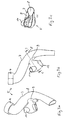
- the Spülkanal Community 5 is in the Figures 3a, 3b and 3c shown in more detail, wherein the dashed line CC in FIG. 3b the sectional plane of the sectional view in Figure 3c shows. It can be seen that the Spülkanal Sa 5 narrows from an initially subsequent to the Spülwasseran gleich 4 larger circular cross-section at a level 7 to a (related to the area) reduced by a factor of 1.5 circular cross-section. This cross-section is maintained downstream of the step 7 in the relatively highly curved piece downstream. This piece is referred to here as narrowing 8.
- the flow cross-section in the region upstream of the step 7 is about 15 cm 2 and downstream within the constriction 8 about 10 cm 2 (the distance in the flow direction between the sectional plane CC in FIG.
- a suction connection 9 is provided on the inside of the bend, the smallest cross-section of which is about 5 cm 2 approximately half of the flow cross-section of the flushing channel in the constriction 8 (here only the circular portion is counted and not the proportion of the terminal 9) and about one third of the cross section upstream thereof.
- FIG. 3c shows in section CC the flushing channel 5 within the constriction 8 and the transition through the suction port 9 to the water separator 10. It can be seen a substantially enlarged cross-section of the water separator 10 compared to the suction port upstream thereof and a slightly sloping to the flushing channel 5 towards bottom of the Wasserabscheiders 10.
- FIGS. 3a and 3b A first is denoted by 11 and is provided at a side opposite to the water flow direction there in the upper region of the water separator 10. He is also in Figure 3c to recognize.
- the actual suction device 13 is connected, in the Figures 1 and 2 is shown symbolically and on the basis of FIG. 4 will be discussed in more detail. (The Figures 1 and 2 Specifically show a suction channel 12 which is connected to the nozzle 11 and leads to a symbolically shown fan 13 out, having an odor filter, not shown.)
- the second connection piece is designated 12 and is also based on FIG. 4 explained in more detail.
- the water separator 10 ensures, in particular, that no water is sucked in despite the operation of the odor extraction device towards the end of the flushing process with decreasing water velocity in the flushing channel piece 5 and thus reduced centrifugal forces in the curvature described. Namely, if the static negative pressure generated by the speed can no longer compensate for the fan vacuum, a drop of water passes through the suction port 9. In the Wasserabschelder the air is significantly slowed down because of the cross-sectional widening, so that the water in the lower part of the water separator 10 remains.
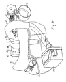
- FIG. 4 shows a perspective view of one in the Figures 1 and 2 partially not shown part of the toilet according to this embodiment.
- the viewing direction is obliquely forward from behind.
- the relation to the Figures 1 and 2 The easiest way to illustrate the course of the Spülkanal Giantal Giant 5 with the level 7 and the constriction 8 and the flushing water connection 4 in FIG. 4 right.
- the water separator 10 Approximately over the middle of the Spülkanal Irish Irishs 5 appears in FIG. 4 the water separator 10, from which points forward to the right (in FIG. 4 ) of the connection piece 11 for the odor removal device and the corresponding suction channel 12 can be seen.
- the channel 12 leads front left to a filter box 13, which has a fan for suction.
- the water tank 14 has approximately a horseshoe shape, to accommodate the upwardly facing knee of the siphon of the toilet.
- the water tank 14 contains the shower water for the in FIG. 4 shower arm 15 shown on the top right, which in operation by the in FIG. 2 drawn breakthrough in the toilet bowl 1 can be extended and retracted.
- the water tank 14 includes a heater and thus forms a hot water boiler for the shower water.
- the right drawn in front of the shower arm 15 structure is the same for extending and retracting the electric motor.
Landscapes
- Health & Medical Sciences (AREA)
- Public Health (AREA)
- Life Sciences & Earth Sciences (AREA)
- Engineering & Computer Science (AREA)
- Hydrology & Water Resources (AREA)
- Water Supply & Treatment (AREA)
- Epidemiology (AREA)
- Sanitary Device For Flush Toilet (AREA)
- Separating Particles In Gases By Inertia (AREA)
Abstract
Description
- Die vorliegende Erfindung betrifft ein Wasserklosett (WC) mit einer Geruchsabsaugeinrichtung.
- WCs mit Spülwasseranschluss sind seit langem in Gebrauch und gängig. Über den Spülwasseranschluss strömt das Spülwasser durch einen Spülkanal und einen Spülwasseraustritt hindurch in eine sogenannte WC-Schüssel, um diese zu spülen. Das gebrauchte Spülwasser läuft dann zusammen mit den weggespülten Inhalten der WC-Schüssel in eine Ablaufleitung, wobei in der Regel ein sogenannter Sifon als Geruchsverschluss vorgesehen ist.
- Es ist ferner an sich bekannt, ein solches WC mit einer Geruchsabsaugeinrichtung auszustatten, die Luft aus der WC-Schüssel ansaugt. Dabei sind sowohl Absaugöffnungen über, aber in der Nähe der WC-Schüssel als auch in der eigentlichen WC-Schüssel verwendet worden. Es ist insbesondere bereits bekannt, den Spülkanal des Spülwassers zum Geruchsabsaugen zu verwenden und die Geruchsabsaugeinrichtung an dem Spülkanal anzuschließen. Sie kann dann, soweit der Spülkanal nicht zum Spülen verwendet wird, durch den Spülwasseraustritt und über den Absauganschluss, nämlich den Anschluss der Geruchsabsaugeinrichtung an dem Spülkanal, Luft und damit störende Gerüche aus der WC-Schüssel ansaugen. Die angesaugte Luft kann zum Beispiel einem Filter zugeführt werden, etwa einem Aktivkohlefilter, und dann wieder in den Raum gelangen. Sie kann auch nach außen geführt oder in eine Abluftanlage eingespeist werden.
- Der Erfindung liegt die technische Aufgabe zugrunde, ein WC mit einer Geruchsabsaugung anzugeben, die in einfacher und gegen Spülwassereintritt geschützter Weise an den Spülkanal angeschlossen ist und dabei einen günstigen Spülkanalverlauf erlaubt.
- Die Aufgabe wird dadurch gelöst, dass der Absauganschluss an einer Stelle des Spülkanals angeordnet ist, die aufgrund von dynamischen Strömungseffekten einer idealen Flüssigkeit einen verringerten oder verschwindenden statischen Druck aufweist. Dies impliziert kein ideales, also reibungsfreies. Strömungsverhalten des Wassers sondern bedeutet lediglich, dass die Erfindung von Reibungsverlusten in der Wasserströmung unabhängig zu einer Druckverminderung an der Anschlussstelle des Absauganschlusses führt und damit nicht zu eigentlich unerwünschten großen Reibungsverlusten aufgrund der Spülkanalform zwingt.
- Dabei gibt es zwei Möglichkeiten, nämlich einerseits die Umlenkung der Strömung durch eine Krümmung und Anordnung des Absauganschlusses auf der Krümmungsinnenseite. Infolge der Fliehkraft des Wassers ist der statische Druck auf der Krümmungsinnenseite, der Saugseite, verringert und auf der Krümmungsaußenseite, der Druckseite, erhöht. Die andere Möglichkeit besteht In der Verengung des Strömungsquerschnitts zur Beschleunigung der Strömung und, nach der näherungsweise geltenden Bemoulli-Gleichung, entsprechenden Verringerung des statischen Drucks. In beiden Fällen ist natürlich angestrebt, den Absauganschluss so zu gestalten, dass der Staudruck des Wassers in dem Absauganschluss wenig oder nicht in Erscheinung tritt. Beide Fälle schließen sich im Übrigen nicht aus sondern sind vorzugsweise kombiniert.
- Bei der ersten Variante ist der Absauganschluss vorzugsweise an der "innersten" Position des (Umfang des) Spülkanals angeordnet. Das ist jedoch nicht zwingend. Der Absauganschluss muss nicht an der bzw. symmetrisch zu der innersten Position sondern kann auch asymmetrisch liegen. Vorzugsweise liegt der Querschnitt des Absauganschlusses insoweit auf der Innenseite, als man auf dem Umfang des Spülkanals als Grenze zwischen der Außenseite und der Innenseite in der (lokalen) Ebene der Krümmung liegende Linien der Spülkanalwand definieren kann. Jedenfalls soll der größte Teil des Querschnitts des Absauganschlusses in diesem Sinn auf der Innenseite liegen.
- Hinsichtlich der zweiten Variante ist der Begriff der Verengung im allgemeinsten Sinn lokal zu verstehen und nicht auf den gesamten Spülkanal bezogen. Vorzugsweise liegen jedoch auf mindestens 10 cm stromabwärts von dem Absauganschluss und vorzugsweise bis zum Spülwasseraustritt nur noch größere Strömungsquerschnitte als in dieser Verengung vor. Umgekehrt gilt das Gleiche vorzugsweise stattdessen bzw. auch stromaufwärts, und zwar vorzugsweise bis zum Spülwasseranschluss. Dabei bezieht sich der Spülwasseranschluss auf den WC-Körper und nicht weitere Spülwasserzuleitungsteile, etwa in einer Installationswand.
- "Parallelgeschaltete" Öffnungen, beispielsweise abwärtsgerichtete Öffnungen entlang eines ringförmigen Spülkanals eines klassischen WCs, sollen dabei hinsichtlich ihrer Strömungsquerschnittsumme gewertet werden.
- Die Verengung sollte relativ zu einer Vergleichsposition am Spülwasseranschluss stromaufwärts davon in einem quantitativen Verhältnis der Querschnitte von 1:1,1 bis 1:2 liegen, wobei in folgender Reihenfolge die Untergrenzen 1:1,2; 1:1,3 sowie 1:1,4 und die Obergrenzen 1:1,9; 1:1,8; 1:1,7 sowie schließlich 1:1,6 zunehmend bevorzugt sind. Ferner ist der minimale Strömungsquerschnitt des Absauganschlusses vorzugsweise gleich oderkleiner als der der Verengung (im Spülkanal selbst), und zwar vorzugsweise in einem Zahlenverhältnis zwischen 1:1 und 1:3, wobei die folgenden Untergrenzen 1,2; 1,4; 1,6; 1,8 und die folgenden Obergrenzen 2,8; 2,6; 2.4; 2,2 für die zweite Zahl in dieser Reihenfolge zunehmend bevorzugt sind. Das Ausführungsbeispiel veranschaulicht diese Verhältnisse mit einem Querschnittsverhältnis von 1:2.
- Ferner kann auch die Spülkanalkrümmung im Bereich des Absauganschlusses in bevorzugten Fällen innerhalb bestimmter quantitativer Grenzen liegen, nämlich gemittelt über einen Winkelbereich von 40° zwischen dem einfachen und dem zehnfachen typischen Innenradius (Wurzel aus (Querschnittsfläche dividiert durch π)) des Spülkanals dort. Dabei sind das Zweifache und Dreifache als Untergrenzen und das Achtfache, Sechsfache und Viereinhalbfache als Obergrenzen weiter bevorzugt.
- Eine weitere Ausgestaltung der Erfindung betrifft einen Wasserabscheider. Dabei handelt es sich um ein Gefäß oder eine mindestens einen Faktor 2 umfassende Querschnittserweiterung auf der Absaugseite des Absauganschlusses (und relativ zu dessen engster Stelle), also außerhalb des Spülkanals, jedoch vorzugsweise in dessen Nähe. An diesem Wasserabscheider kann die Geruchsabsaugeinrichtung angeschlossen sein, und zwar vorzugsweise in dessen oberem Bereich. Damit kann trotz der erfindungsgemäßen Maßnahmen dennoch durch den Absauganschluss eingetretenes Wasser im unteren Bereich bzw. auf dem Boden des Wasserabscheiders abgefangen werden und tritt nicht oder nur in vernachlässigbaren Mengen in den Anschluss der Geruchsabsaugeinrichtung ein. Der Wasserabscheider funktioniert also durch die Schwerkraft des Wassers. Das darin abgeschiedene Wasser kann gesammelt und anderweitig abgeführt werden. Bei einer bevorzugten Ausgestaltung wird es durch eine Neigung des Wasserabscheiderbodens zum Spülkanal zurückgeführt.
- Im Übrigen ist die Geruchsabsaugeinrichtung vorzugsweise nicht nur im oberen Bereich des Wasserabscheiders angeschlossen sondern dort in einem der Spülwasserströmung entgegengesetzten Bereich. Damit ist gemeint, dass mit der Spülwasserströmung eintretende Spülwasserreste mit einer bestimmten Strömungsrichtung im Spülkanal und von diesem in den Wasserabscheider hineingeströmt sind und damit vorzugsweise auf eine entsprechende Seite des Wasserabscheiders treffen. Die bevorzugte Position für den Anschluss der Geruchsabsaugeinrichtung ist entgegengesetzt, wie das Ausführungsbeispiel veranschaulicht.
- Der Wasserabscheider kann zudem in Kombination mit einem Dusch-WC, also einer Duscheinrichtung des WCs, dazu genutzt werden, einen Wasserüberlauf eines Wassertanks der Duscheinrichtung an dem Wasserabscheider anzuschließen, und zwar vorzugsweise in einem oberen Bereich desselben. Die Duscheinrichtung muss nicht zwingend in dem WC integriert sein; sie kann auch ein Aufsatz oder ein anderweitig nachgerüstetes oder baulich separates Tell sein.
- Die erfindungsgemäßen Maßnahmen können einzeln und besonders in Kombination das Eintreten von Spülwasser in die Geruchsabsaugeinrichtung einschränken und verhindern, und zwar indem aufgrund der erläuterten Strömungseffekte nur noch wenig oder kein Wasser durch den Absauganschluss hindurchtritt. Hierbei handelt es sich um eine elegante und einfache Lösung. Sie vermeidet zudem die mit konventionellen Ventilen oder Klappen zur Verhinderung des Eintretens von Spülwasser in eine Geruchsabsaugeinrichtung verbundenen Probleme im Hinblick auf technischen Aufwand, Bauvolumen, Kosten, Wartungsfälligkeit und Wartungsintensität etc. Vorzugsweise wird die Erfindung mithin dafür genutzt, in der Zuleitung der Geruchsabsaugeinrichtung ab einschließlich dem Absauganschluss keine solchen Klappen und Ventile vorzusehen und diese Zuleitung freizuhalten.
- Ferner wurde bereits erläutert, dass die Ausnutzung von Strömungseffekten einer idealen Flüssigkeit, die also nicht von der inneren Reibung abhängen, die Möglichkeit einer strömungstechnisch bzw. drucktechnisch geschickten Anordnung des Absauganschlusses bei gleichzeitig geringem Gesamtströmungswiderstand des Spülkanals erlaubt. Dies ist besonders von Bedeutung im Zusammenhang mit gravimetrischen Strömungen, also solchen, die aufgrund der Schwerkraft des Spülwassers und ohne eine WC-inteme Spülwasserzufuhrpumpe, arbeiten. Das klassische Beispiel ist ein WC mit einem Spülkasten, der höher als die WC-Schüssel angeordnet ist. In diesem Zusammenhang ist eine strömungstechnisch günstige Gestaltung des Spülkanals vor allem dann von Vorteil, wenn mit aus ökologischen und ökonomischen Gründen reduzierten Spülwassermengen gearbeitet werden soll. Dabei kann es sich vorzugsweise um einen Unterputzspülkasten und insbesondere einen in einem wandseitigen Montagerahmen montierten Unterputzspülkasten handeln.
- Wenn in der beschriebenen Weise eine effektive Strömung des Spülwassers durch den Spülkanal sichergestellt werden kann, verbessert das nicht nur die Spülwirkung vergleichsweise geringer Spülwassermengen in der Spülschüssel sondern erhöht auch die kinetische Energie des Spülwassers bei dem Durchtritt durch die Ableitung, also insbesondere durch einen Sifon. Insoweit ist die Erfindung auch bei WCs mit einem statischen Sifon vorteilhaft. Darunter versteht man einen Sifon, der ohne eine zusätzliche mechanische Betätigung, etwa durch eine Klappe oder Ähnliches, funktioniert. Die Erfindung ist ferner vorteilhaft bei WCs, die zu Reduktion des Spülwasserverbrauchs auch auf eine separate Austrittsdüse des Spülwassers knapp über dem Sifon verzichten. Solche Austrittsdüsen sind an sich bekannt und dienen zur Beschleunigung des Spülwassers im Sifonbereich. Im Zusammenhang mit einer relativ schnellen Spülwasserströmung kann darauf vorteilhafterweise verzichtet werden.
- Schließlich kann die kinetische Energie des Spülwassers auch dadurch ausgenutzt und sogar erhöht werden, dass das Spülwasser möglichst störungsfrei in die WC-Schüssel eintritt und dort mit einer überwiegenden Tangentialgeschwindigkeitskomponente einströmt, um rotierend durch die Schüssel zum Sifon zu gelangen.
- Im Folgenden wird die Erfindung anhand eines Ausführungsbeispiels näher erläutert, wobei die einzelnen Merkmale auch in anderen Kombinationen erfindungswesentlich sein können.
- Figur 1
- zeigt eine Draufsicht auf ein erfindungsgemäßes WC.
- Figur 2
- entspricht weitgehend
Figur 1 , zeigt aber eine teils geschnittene Draufsicht mit einer geringfügig unter der Oberkante des WC liegenden horizontalen Schnittebene. - Figuren 3a, 3b und 3c
- zeigen eine perspektivische Ansicht, eine Draufsicht und einen Schnitt entlang einer mit C-C bezeichneten Ebene zu einem Spülkanalstück aus
Figur 2 . - Figur 4
- zeigt eine perspektivische rückseitige Ansicht eines Teils des WCs aus den
Figuren 1 und 2 . -
Figur 1 zeigt eine Draufsicht auf ein erfindungsgemäßes WC. Mit 1 ist eine mittige WC-Schüssel und mit 2 ein WC-Sitzring (beziehungsweise eine sogenannte WC-Brille) bezeichnet. 3 bezeichnet einen Spülwasserablauf konventioneller Art, der über einen Sifon mit dem Wasserspiegel innerhalb der WC-Schüssel 1 verbunden ist und 4 bezeichnet einen Spülwasseranschluss. Soweit ist das WC ausFigur 1 (mit Ausnahme der später erläuterten Gestaltung des Spülwasseraustritts in der Schüssel 1) konventionell. - Von dem Spülwasseranschluss 4 aus führt ein gekrümmtes Rohrstück 5 zur in
Figur 1 rechten oberen Seite der Schüssel 1.Figur 2 zeigt eine Schnittdarstellung durch eine etwas tiefer liegende Ebene und insbesondere das Rohrstück 5, nämlich das hier sogenannte Spülkanalstück, etwas vollständiger. Es mündet in eine Spülwasserdüse 6, die als Spülwasseraustritt an der in denFiguren 1 und 2 rechten Seite der Spülschüssel 1 fungiert. Diese Düse 6 führt das Spülwasser mit tangentialer Geschwindigkeitsrichtung im oberen Bereich der WC-Schüssel 1 ein, sodass sich eine rotierende, und, insbesondere im Vergleich zu einem klassischen Spülrand mit einer Vielzahl kleiner Austrittsöffnungen, schnelle Spülwasserströmung in der WC-Schüssel 1 ergibt. Die Spüldüse 6 als Spülwasseraustritt und das Kanalstück 5 bilden gemeinsam den Spülkanal. -
Figur 2 zeigt ferner im hinteren Bereich der WC-Schüssel 1 zwei in deren Keramikstruktur eingeformte Durchtritte für einen Duscharm (zentrisch) und links daneben einen Fönarm. Es handelt sich mithin um ein Dusch-WC. - Das Spülkanalstück 5 ist in den
Figuren 3a, 3b und 3c detaillierter dargestellt, wobei die strichpunktierte Linie C-C inFigur 3b die Schnittebene der Schnittdarstellung inFigur 3c zeigt. Man erkennt dabei, dass sich das Spülkanalstück 5 von einem anfänglich anschließend an den Spülwasseranschluss 4 größeren kreisförmigen Querschnitt an einer Stufe 7 zu einem (ftächenbezogen) um den Faktor 1,5 verringerten kreisförmigen Querschnitt verengt. Dieser Querschnitt wird in dem relativ stark gebogenen Stück stromabwärts anschließend an die Stufe 7 beibehalten. Dieses Stück wird hier als Verengung 8 bezeichnet. Der Strömungsquerschnitt in dem Bereich stromaufwärts der Stufe 7 beträgt etwa 15 cm2 und stromabwärts innerhalb der Verengung 8 etwa 10 cm2 (wobei der Abstand in Strömungsrichtung zwischen der Schnittebene C-C inFigur 3b und dem der Stufe 7 entsprechenden Teil des Spülkanalstücks 5 ungefähr 4 cm beträgt). Stromaufwärts verändert sich der Strömungsquerschnitt bis zum Spülwasseranschluss 4 nicht mehr wesentlich, stromabwärts öffnet er sich nach der Krümmung und Verengung 8 flächenmäßig wieder etwas, und zwar im Wesentlichen durch eine zunehmende Höhe. Das kann man ansatzweise inFigur 3a und auch in der weiter unten noch beschriebenenFigur 4 erkennen. Im Übrigen ist der Verlauf des Spülkanalstücks 5 stromabwärts wieder gerader und die Querschnittsform passt sich dabei der aufrechten Form der Spüldüse 6 an, wieFigur 3a im Vergleich mitFigur 2 zeigt. - In der Verengung 8 treten ersichtlich zwei strömungsdynamische Effekte gleichzeitig auf, nämlich zum einen die Erzeugung eines statischen Unterdrucks an der Krümmungsinnenseite infolge der Zentrifugalkräfte und zum anderen ein Venturi-Effekt infolge der Stufe 7 durch Erhöhung der Strömungsgeschwindigkeit innerhalb der Verengung 8. Beide Effekte gemeinsam halten die Geruchsabsaugeinrichtung ohne weltere Maßnahmen wie Ventile oder Klappen wasserfrei.
- Im Bereich der Verengung 8 ist auf der Innenseite der Krümmung ein Absauganschluss 9 vorgesehen, dessen geringster Querschnitt mit etwa 5 cm2 ungefähr der Hälfte des Strömungsquerschnitts des Spülkanals In der Verengung 8 (hier wird nur der kreisförmige Anteil gezählt und nicht der Anteil des Anschlusses 9) und ungefähr einem Drittel des Querschnitts stromaufwärts davon entspricht.
- An den entsprechenden verengten Durchlass dieses Absauganschlusses 9 schließt sich ein topfartiger Wasserabscheider 10 an.
Figur 3c zeigt im Schnitt C-C den Spülkanal 5 innerhalb der Verengung 8 und den Übergang durch den Absauganschluss 9 zu dem Wasserabscheider 10. Man erkennt einen wesentlich vergrößerten Querschnitt des Wasserabscheiders 10 im Vergleich zu dem Ansauganschluss stromaufwärts davon und einen zu dem Spülkanal 5 hin leicht abfallenden Boden des Wasserabscheiders 10. Damit läuft das Wasser, auch wenn es in den Wasserabscheider hineingelangen sollte, letztlich wieder zurück. - Ferner erkennt man vor allem in den
Figuren 3a und 3b zwei Anschlussstutzen an der Oberseite des Wasserabscheiders 10. Ein erster ist mit 11 bezeichnet und ist an eine der Wasserströmungsrichtung entgegengesetzten Seite dort im oberen Bereich des Wasserabscheiders 10 vorgesehen. Er ist ferner auch inFigur 3c zu erkennen. Hier ist die eigentliche Absaugeinrichtung 13 angeschlossen, die in denFiguren 1 und 2 symbolisch dargestellt ist und auf die anhand vonFigur 4 noch näher eingegangen wird. (DieFiguren 1 und 2 zeigen konkret einen Absaugkanal 12, der an den Stutzen 11 angeschlossen ist und zu einem symbolisch dargestellten Lüfter 13 hin führt, der einen nicht näher dargestellten Geruchsfilter aufweist.) - Der zweite Anschlussstutzen ist mit 12 bezeichnet und wird ebenfalls anhand von
Figur 4 näher erläutert. - Der Wasserabscheider 10 sorgt insbesondere dafür, dass gegen Ende des Spülvorgangs bei abnehmender Wassergeschwindigkeit im Spülkanalstück 5 und damit verringerten Zentrifugalkräften in der beschriebenen Krümmung trotz Betrieb der Geruchsabsaugeinrichtung kein Wasser angesaugt wird. Wenn nämlich der durch die Geschwindigkeit erzeugte statische Unterdruck den Lüfterunterdruck nicht mehr kompensieren kann, tritt zwar ein Wassertropfen durch den Absauganschluss 9 hindurch. In dem Wasserabschelder wird die Luft aber wegen der Querschnittserweiterung deutlich verlangsamt, sodass das Wasser im unteren Teil des Wasserabscheiders 10 verbleibt.
-
Figur 4 zeigt eine perspektivische Darstellung eines in denFiguren 1 und 2 teilweise nicht dargestellten Teils des WCs gemäß diesem Ausführungsbeispiel. Die Blickrichtung ist von hinten schräg nach vorne. Den Bezug zu denFiguren 1 und 2 verdeutlich man sich am einfachsten anhand des Verlaufs des Spülkanalstücks 5 mit der Stufe 7 und der Verengung 8 sowie dem Spülwasseranschluss 4 inFigur 4 rechts. Ungefähr über der Mitte des Spülkanalstücks 5 erscheint inFigur 4 der Wasserabscheider 10, von dem aus nach vorne rechts weisend (inFigur 4 ) der Anschlussstutzen 11 für die Geruchsabsaugeinrichtung und der entsprechende Absaugkanal 12 zu sehen sind. Der Kanal 12 führt vorne links zu einer Filterbox 13, die ein Gebläse zum Ansaugen aufweist. Der inFigur 4 nach vorne rechts weisende kleine quadratische Anschlussstutzen trägt den Filter, während die größere rechteckige Öffnung nach oben zur Revision dient. Man erkennt im Übrigen, dass die tatsächliche geometrische Anordnung der Leitung 12 und der Filterbox 13 etwas von denFiguren 1 und 2 abweicht und inFigur 4 die WC-Schüssel 1 fehlt. - Von dem Wasserabscheider 10 geht nach hinten links über den Anschlussstutzen 12 eine weitere Kanalleitung 13 nach unten und ist als Funktionsüberlauf an einem Wassertank 14 einer Duscheinrichtung angeschlossen. Der Wassertank 14 hat näherungsweise eine Hufeisenform, und zwar zur Anpassung an das nach oben weisende Knie des Sifons des WCs. Der Wassertank 14 beinhaltet das Duschwasser für den in
Figur 4 rechts oben dargestellten Duscharm 15, der im Betrieb durch den inFigur 2 eingezeichneten Durchbruch in der WC-Schüssel 1 ein- und ausgefahren werden kann. Der Wassertank 14 enthält eine Heizeinrichtung und bildet somit einen Warmwasserboiler für das Duschwasser. Die rechts vor dem Duscharm 15 gezeichnete Struktur ist der Elektromotor zum Aus- und Einfahren desselben. - Falls es zum Beispiel aufgrund eines Defekts zu einem Überfüllen des Wassertanks 14 kommt, so läuft das Wasser durch den Kanal 13 und den Wasserabscheider 10 letztlich über den Spülkanal in die WC-Schüssel 1 und damit durch den Ablauf derselben gefahrlos ab. Dabei bleibt die Geruchsabsaugeinrichtung unbeeinträchtigt, weil der Kanal 12 eine ausreichende Höhe erreicht. Im Übrigen besteht keine Gefahr des versehentlichen Ansaugens von Falschluft durch den Kanal 13, weil der Wassertank 14 im Betriebszustand mit Wasser gefüllt ist.
Claims (15)
- WC mit
einem Spülwasseranschluss (4),
einem Spülwasseraustritt (6) in eine WC-Schüssel (1),
einem Spülkanal (5, 6), der den Spülwasseranschluss (4) und den Spülwasseraustritt (6) verbindet und
einer Geruchsabsaugeinrichtung (12, 13), die an den Spülkanal (5, 6) über einen Absauganschluss (9) angeschlossen ist, um Luft durch den Spülwasseraustritt (6) und den Absauganschluss (9) aus der WC-Schüssel (1) anzusaugen,
dadurch gekennzeichnet, dass der Absauganschluss (9) in einer Krümmung (8) des Spülkanals (5, 6) auf der Krümmungsinnenseite angeordnet ist. - WC, auch nach Anspruch 1, mit
einem Spülwasseranschluss (4),
einem Spülwasseraustritt (6) in eine WC-Schüssel (1),
einem Spülkanal (5, 6), der den Spülwasseranschluss (4) und den Spülwasseraustritt (6) verbindet und
einer Geruchsabsaugeinrichtung (12, 13), die an den Spülkanal (5, 6) über einen Absauganschluss (9) angeschlossen ist, um Luft durch den Spülwasseraustritt (6) und den Absauganschluss (9) aus der WC-Schüssel (1) anzusaugen,
dadurch gekennzeichnet, dass der Absauganschluss (9) innerhalb einer Verengung (8) des Spülkanals (5, 6) angeordnet ist. - WC nach Anspruch 2, bei dem der Spülkanal (5, 6) für mindestens 10 cm stromabwärts von dem Absauganschluss (9) und vorzugsweise bis zum Spülwasseraustritt (6) nur noch größere Strömungsquerschnitte als in der Verengung (8) aufweist und/oder bei dem der Spülkanal (5, 6) für mindestens 10 cm stromaufwärts von dem Absauganschluss (9) und vorzugsweise bis zu dem Spülwasseranschluss (4) nur noch größere Strömungsquerschnitte als in der Verengung (8) aufweist.
- WC nach Anspruch 2 oder 3, bei dem die Verengung (8) relativ zu einem Querschnitt des Spülwasseranschlusses (4) in einem Verhältnis von 1:1,1 und 1:2 liegt.
- WC nach Anspruch 2, 3 oder 4, bei dem der Absauganschluss (9) einen minimalen Querschnitt aufweist, der in einem Verhältnis zwischen 1:1 und 1:3 zu der Verengung (8) steht.
- WC nach Anspruch 1, auch in Verbindung mit einem der Ansprüche 2 bis 5, bei dem die Krümmung (8) des Spülkanals (5, 6) im Bereich des Absauganschlusses (9) über einen Winkelbereich von 40° einen gemittelten Krümmungsradius zwischen dem einfachen und zehnfachen typischen Innenradius des Spülkanals (5, 6) dort aufweist.
- WC nach einem der vorstehenden Ansprüche, bei dem sich an dem Absauganschluss (9) absaugseitig ein im Querschnitt um mindestens einen Faktor 2 gegenüber dem Absauganschluss (9) erweiterter Wasserabscheider (10) anschließt, in dessen oberem Bereich (11) die Geruchsabsaugeinrichtung (12, 13) angeschlossen ist.
- WC nach Anspruch 7, bei dem der Boden des Wasserabscheiders (10) zum Spülkanal (5, 6) hin abfällt.
- WC nach Anspruch 7 oder 8, bei dem die Geruchsabsaugeinrichtung (12, 13) in einem spülwasserströmungsentgegengesetzten oberen Bereich (11) des Wasserabscheiders (10) angeschlossen ist.
- WC nach Anspruch 7, 8 oder 9, bei dem das WC eine Duscheinrichtung (15) aufweist und ein Wasserüberlauf eines Duschwassertanks (14) der Duscheinrichtung (15) in einem oberen Bereich (12) des Wasserabscheiders (10) angeschlossen ist.
- WC nach einem der vorstehenden Ansprüche, bei dem eine Geruchsabsaugleitung (10, 11, 12) zwischen dem Absauganschluss (9) und der Geruchsabsaugeinrichtung (12, 13) klappen- und ventilfrei ist.
- WC nach einem der vorstehenden Ansprüche mit einer rein gravimetrischen, das heißt ohne WC-interne Spülwasserzufuhrpumpe arbeitenden, Spülung.
- WC nach einem der vorstehenden Ansprüche mit einem statischen Sifon.
- WC nach einem der vorstehenden Ansprüche, bei dem der Spülwasseraustritt (6) in die WC-Schüssel (1) dergestalt endet (6), das das Spülwasser mit einer überwiegenden Tangentialgeschwindigkeitskomponente bezogen auf die Schüsselinnenform in die Schüssel (1) strömt und in der Schüssel (1) eine rotierende Bewegung vollzieht.
- WC-Anlage mit einem WC nach einem der vorstehenden Ansprüche und einem Spülkasten, vorzugsweise Unterputzspülkasten, insbesondere einem in einem wandseitigen Montagerahmen montierten Unterputzspülkasten.
Priority Applications (6)
| Application Number | Priority Date | Filing Date | Title |
|---|---|---|---|
| EP12004070.4A EP2666917B1 (de) | 2012-05-25 | 2012-05-25 | WC mit Geruchsabsaugeinrichtung |
| ES12004070.4T ES2562615T3 (es) | 2012-05-25 | 2012-05-25 | Retrete con dispositivo de absorción de olores |
| DK12004070.4T DK2666917T3 (en) | 2012-05-25 | 2012-05-25 | WC with odor extraction device |
| PL12004070T PL2666917T3 (pl) | 2012-05-25 | 2012-05-25 | Ustęp spłukiwany wodą z urządzeniem do odsysania odorów |
| CN201380024668.3A CN104302850B (zh) | 2012-05-25 | 2013-05-24 | 带除味单元的抽水马桶 |
| PCT/EP2013/001526 WO2013174516A1 (en) | 2012-05-25 | 2013-05-24 | Wc with odour extractor |
Applications Claiming Priority (1)
| Application Number | Priority Date | Filing Date | Title |
|---|---|---|---|
| EP12004070.4A EP2666917B1 (de) | 2012-05-25 | 2012-05-25 | WC mit Geruchsabsaugeinrichtung |
Publications (2)
| Publication Number | Publication Date |
|---|---|
| EP2666917A1 true EP2666917A1 (de) | 2013-11-27 |
| EP2666917B1 EP2666917B1 (de) | 2016-01-13 |
Family
ID=48520896
Family Applications (1)
| Application Number | Title | Priority Date | Filing Date |
|---|---|---|---|
| EP12004070.4A Active EP2666917B1 (de) | 2012-05-25 | 2012-05-25 | WC mit Geruchsabsaugeinrichtung |
Country Status (6)
| Country | Link |
|---|---|
| EP (1) | EP2666917B1 (de) |
| CN (1) | CN104302850B (de) |
| DK (1) | DK2666917T3 (de) |
| ES (1) | ES2562615T3 (de) |
| PL (1) | PL2666917T3 (de) |
| WO (1) | WO2013174516A1 (de) |
Families Citing this family (3)
| Publication number | Priority date | Publication date | Assignee | Title |
|---|---|---|---|---|
| CN106812197B (zh) | 2015-12-01 | 2019-10-18 | 哈尼·A·阿布纳梅赫 | 马桶便盆排气系统 |
| CR20160359U (es) * | 2016-08-10 | 2016-09-13 | Eduardo Quesada Castro Roiman | Extractor de olor para inodoros mejorado |
| DK3444408T3 (da) * | 2017-08-18 | 2020-12-21 | Geberit Int Ag | Toilet med skyllevandsforbindelse |
Citations (4)
| Publication number | Priority date | Publication date | Assignee | Title |
|---|---|---|---|---|
| DE1658276B1 (de) * | 1967-05-05 | 1971-05-13 | Koelle Kurt Dipl Ing | Entlueftungsvorrichtung fuer ein Spuelklosett |
| DE4313406A1 (de) * | 1992-04-24 | 1993-10-28 | Ludwig Pilsl | Luftabsaugvorrichtung für ein Spülklosett |
| GB2350845A (en) * | 1999-05-14 | 2000-12-13 | John Hugh Mccool | Overflow fitting for a flushing cistern |
| EP1369537A1 (de) * | 2002-06-07 | 2003-12-10 | Giuseppe Di Giovanni | Vorrichtung zur Beseitigung unerwünschter Gerüche aus einer Toilettenschüssel |
Family Cites Families (10)
| Publication number | Priority date | Publication date | Assignee | Title |
|---|---|---|---|---|
| DE1759613A1 (de) * | 1968-05-18 | 1971-06-16 | Juergen Hannemann | Entlueftungsvorrichtung fuer WC-Spuelbecken |
| JPS6429531A (en) * | 1987-07-23 | 1989-01-31 | Inax Corp | Closet with ozone generator |
| JPH01271545A (ja) * | 1988-04-23 | 1989-10-30 | Toto Ltd | 脱臭機能を有する水洗便器 |
| JPH02176030A (ja) * | 1988-12-27 | 1990-07-09 | Shuichi Umeda | 便臭瞬間排気便器設備 |
| CA2039929A1 (en) * | 1991-04-08 | 1992-10-09 | Paul J. Boisvert | Toilet vent adaptor |
| CN2116726U (zh) * | 1992-04-15 | 1992-09-23 | 李德武 | 卫生间异味排除及换气装置 |
| JP3034407B2 (ja) * | 1993-09-17 | 2000-04-17 | アイシン精機株式会社 | 脱臭機能付き洗浄便座装置 |
| DE9411849U1 (de) * | 1994-07-22 | 1994-11-03 | Rehfuß, Bernd, Dipl.-Ing., 59427 Unna | Netzunabhängige Toilettengeruchsabsauganlage für tiefhängende Spülkästen mit normierten Kunststoffspül- und -abwasserrohr |
| EP1725803A1 (de) * | 2004-03-02 | 2006-11-29 | Herbert Maria Degens | Rohransatz |
| JP4830439B2 (ja) * | 2005-10-06 | 2011-12-07 | パナソニック株式会社 | トイレ装置 |
-
2012
- 2012-05-25 ES ES12004070.4T patent/ES2562615T3/es active Active
- 2012-05-25 EP EP12004070.4A patent/EP2666917B1/de active Active
- 2012-05-25 PL PL12004070T patent/PL2666917T3/pl unknown
- 2012-05-25 DK DK12004070.4T patent/DK2666917T3/en active
-
2013
- 2013-05-24 WO PCT/EP2013/001526 patent/WO2013174516A1/en not_active Ceased
- 2013-05-24 CN CN201380024668.3A patent/CN104302850B/zh active Active
Patent Citations (4)
| Publication number | Priority date | Publication date | Assignee | Title |
|---|---|---|---|---|
| DE1658276B1 (de) * | 1967-05-05 | 1971-05-13 | Koelle Kurt Dipl Ing | Entlueftungsvorrichtung fuer ein Spuelklosett |
| DE4313406A1 (de) * | 1992-04-24 | 1993-10-28 | Ludwig Pilsl | Luftabsaugvorrichtung für ein Spülklosett |
| GB2350845A (en) * | 1999-05-14 | 2000-12-13 | John Hugh Mccool | Overflow fitting for a flushing cistern |
| EP1369537A1 (de) * | 2002-06-07 | 2003-12-10 | Giuseppe Di Giovanni | Vorrichtung zur Beseitigung unerwünschter Gerüche aus einer Toilettenschüssel |
Also Published As
| Publication number | Publication date |
|---|---|
| WO2013174516A1 (en) | 2013-11-28 |
| EP2666917B1 (de) | 2016-01-13 |
| CN104302850B (zh) | 2016-10-26 |
| DK2666917T3 (en) | 2016-03-21 |
| PL2666917T3 (pl) | 2016-06-30 |
| CN104302850A (zh) | 2015-01-21 |
| ES2562615T3 (es) | 2016-03-07 |
Similar Documents
| Publication | Publication Date | Title |
|---|---|---|
| EP2628546B1 (de) | Duscharm für Dusch-WC | |
| EP3768905B1 (de) | Trenntoilette | |
| EP3951110B1 (de) | Spültoilette | |
| DE112017006572T5 (de) | Spültoilette | |
| EP2604761A1 (de) | Wasserklosett | |
| EP2886729B1 (de) | Toilettenschüssel und Toilette | |
| EP3412840B1 (de) | Wasserklosett | |
| DE102019105730A1 (de) | Sanitärgegenstand in Form eines WCs | |
| EP2666917B1 (de) | WC mit Geruchsabsaugeinrichtung | |
| DE202015003331U1 (de) | Wandablauf mit Siphon-Geruchsverschluss | |
| DE202021106357U1 (de) | Toilette mit Wasserspülung | |
| EP2275610B1 (de) | Wasserkasten für ein Klosett und entsprechendes Klosett | |
| AT5032U1 (de) | Absaugesiphon für eine spüleinrichtung | |
| DE202012005145U1 (de) | WC mit Geruchsabsaugungseinrichtung | |
| EP1484453B1 (de) | Uberlauf- und Ablaufgarnitur für sanitäre Apparate | |
| DE1902751A1 (de) | Wasserclosett | |
| EP0185109B1 (de) | Geruchsverschluss | |
| DE112017006579T5 (de) | Spültoilette | |
| DE19706620B4 (de) | Abtrenneinrichtung für Regenwasser | |
| DE10065985A1 (de) | Toilettenschüssel | |
| EP3569134A1 (de) | Reinigungs- und/oder desinfektionsautomat | |
| DE102023123249A1 (de) | Anordnungssystem zur Anordnung eines Spülbehälters eines Sanitärausstattungsgegenstandes | |
| EP3567169B1 (de) | Ablaufgarnitur | |
| EP1175534B1 (de) | Wassersparende toilettenanlage | |
| DE2212112C3 (de) | Entlüftungsvorrichtung |
Legal Events
| Date | Code | Title | Description |
|---|---|---|---|
| PUAI | Public reference made under article 153(3) epc to a published international application that has entered the european phase |
Free format text: ORIGINAL CODE: 0009012 |
|
| 17P | Request for examination filed |
Effective date: 20130301 |
|
| AK | Designated contracting states |
Kind code of ref document: A1 Designated state(s): AL AT BE BG CH CY CZ DE DK EE ES FI FR GB GR HR HU IE IS IT LI LT LU LV MC MK MT NL NO PL PT RO RS SE SI SK SM TR |
|
| AX | Request for extension of the european patent |
Extension state: BA ME |
|
| RBV | Designated contracting states (corrected) |
Designated state(s): AL AT BE BG CH CY CZ DE DK EE ES FI FR GB GR HR HU IE IS IT LI LT LU LV MC MK MT NL NO PL PT RO RS SE SI SK SM TR |
|
| 17Q | First examination report despatched |
Effective date: 20141027 |
|
| GRAP | Despatch of communication of intention to grant a patent |
Free format text: ORIGINAL CODE: EPIDOSNIGR1 |
|
| RIC1 | Information provided on ipc code assigned before grant |
Ipc: E03D 9/052 20060101AFI20150819BHEP Ipc: E03D 9/05 20060101ALI20150819BHEP Ipc: E03D 1/38 20060101ALI20150819BHEP |
|
| INTG | Intention to grant announced |
Effective date: 20150904 |
|
| GRAS | Grant fee paid |
Free format text: ORIGINAL CODE: EPIDOSNIGR3 |
|
| GRAA | (expected) grant |
Free format text: ORIGINAL CODE: 0009210 |
|
| AK | Designated contracting states |
Kind code of ref document: B1 Designated state(s): AL AT BE BG CH CY CZ DE DK EE ES FI FR GB GR HR HU IE IS IT LI LT LU LV MC MK MT NL NO PL PT RO RS SE SI SK SM TR |
|
| REG | Reference to a national code |
Ref country code: GB Ref legal event code: FG4D Free format text: NOT ENGLISH |
|
| REG | Reference to a national code |
Ref country code: CH Ref legal event code: EP |
|
| REG | Reference to a national code |
Ref country code: CH Ref legal event code: NV Representative=s name: BOVARD AG, CH |
|
| REG | Reference to a national code |
Ref country code: IE Ref legal event code: FG4D Free format text: LANGUAGE OF EP DOCUMENT: GERMAN |
|
| REG | Reference to a national code |
Ref country code: AT Ref legal event code: REF Ref document number: 770625 Country of ref document: AT Kind code of ref document: T Effective date: 20160215 |
|
| REG | Reference to a national code |
Ref country code: DE Ref legal event code: R096 Ref document number: 502012005691 Country of ref document: DE |
|
| REG | Reference to a national code |
Ref country code: ES Ref legal event code: FG2A Ref document number: 2562615 Country of ref document: ES Kind code of ref document: T3 Effective date: 20160307 |
|
| REG | Reference to a national code |
Ref country code: DK Ref legal event code: T3 Effective date: 20160318 |
|
| REG | Reference to a national code |
Ref country code: PT Ref legal event code: SC4A Free format text: AVAILABILITY OF NATIONAL TRANSLATION Effective date: 20160404 |
|
| REG | Reference to a national code |
Ref country code: SE Ref legal event code: TRGR |
|
| REG | Reference to a national code |
Ref country code: NL Ref legal event code: FP |
|
| REG | Reference to a national code |
Ref country code: NO Ref legal event code: T2 Effective date: 20160113 |
|
| REG | Reference to a national code |
Ref country code: LT Ref legal event code: MG4D |
|
| REG | Reference to a national code |
Ref country code: FR Ref legal event code: PLFP Year of fee payment: 5 |
|
| REG | Reference to a national code |
Ref country code: SK Ref legal event code: T3 Ref document number: E 20447 Country of ref document: SK |
|
| PG25 | Lapsed in a contracting state [announced via postgrant information from national office to epo] |
Ref country code: HR Free format text: LAPSE BECAUSE OF FAILURE TO SUBMIT A TRANSLATION OF THE DESCRIPTION OR TO PAY THE FEE WITHIN THE PRESCRIBED TIME-LIMIT Effective date: 20160113 Ref country code: GR Free format text: LAPSE BECAUSE OF FAILURE TO SUBMIT A TRANSLATION OF THE DESCRIPTION OR TO PAY THE FEE WITHIN THE PRESCRIBED TIME-LIMIT Effective date: 20160414 Ref country code: FI Free format text: LAPSE BECAUSE OF FAILURE TO SUBMIT A TRANSLATION OF THE DESCRIPTION OR TO PAY THE FEE WITHIN THE PRESCRIBED TIME-LIMIT Effective date: 20160113 |
|
| PG25 | Lapsed in a contracting state [announced via postgrant information from national office to epo] |
Ref country code: LV Free format text: LAPSE BECAUSE OF FAILURE TO SUBMIT A TRANSLATION OF THE DESCRIPTION OR TO PAY THE FEE WITHIN THE PRESCRIBED TIME-LIMIT Effective date: 20160113 Ref country code: LT Free format text: LAPSE BECAUSE OF FAILURE TO SUBMIT A TRANSLATION OF THE DESCRIPTION OR TO PAY THE FEE WITHIN THE PRESCRIBED TIME-LIMIT Effective date: 20160113 Ref country code: IS Free format text: LAPSE BECAUSE OF FAILURE TO SUBMIT A TRANSLATION OF THE DESCRIPTION OR TO PAY THE FEE WITHIN THE PRESCRIBED TIME-LIMIT Effective date: 20160513 Ref country code: RS Free format text: LAPSE BECAUSE OF FAILURE TO SUBMIT A TRANSLATION OF THE DESCRIPTION OR TO PAY THE FEE WITHIN THE PRESCRIBED TIME-LIMIT Effective date: 20160113 Ref country code: BE Free format text: LAPSE BECAUSE OF NON-PAYMENT OF DUE FEES Effective date: 20160531 |
|
| REG | Reference to a national code |
Ref country code: DE Ref legal event code: R097 Ref document number: 502012005691 Country of ref document: DE |
|
| PG25 | Lapsed in a contracting state [announced via postgrant information from national office to epo] |
Ref country code: EE Free format text: LAPSE BECAUSE OF FAILURE TO SUBMIT A TRANSLATION OF THE DESCRIPTION OR TO PAY THE FEE WITHIN THE PRESCRIBED TIME-LIMIT Effective date: 20160113 |
|
| PLBE | No opposition filed within time limit |
Free format text: ORIGINAL CODE: 0009261 |
|
| STAA | Information on the status of an ep patent application or granted ep patent |
Free format text: STATUS: NO OPPOSITION FILED WITHIN TIME LIMIT |
|
| PG25 | Lapsed in a contracting state [announced via postgrant information from national office to epo] |
Ref country code: SM Free format text: LAPSE BECAUSE OF FAILURE TO SUBMIT A TRANSLATION OF THE DESCRIPTION OR TO PAY THE FEE WITHIN THE PRESCRIBED TIME-LIMIT Effective date: 20160113 Ref country code: RO Free format text: LAPSE BECAUSE OF FAILURE TO SUBMIT A TRANSLATION OF THE DESCRIPTION OR TO PAY THE FEE WITHIN THE PRESCRIBED TIME-LIMIT Effective date: 20160113 |
|
| 26N | No opposition filed |
Effective date: 20161014 |
|
| PG25 | Lapsed in a contracting state [announced via postgrant information from national office to epo] |
Ref country code: LU Free format text: LAPSE BECAUSE OF FAILURE TO SUBMIT A TRANSLATION OF THE DESCRIPTION OR TO PAY THE FEE WITHIN THE PRESCRIBED TIME-LIMIT Effective date: 20160525 |
|
| PG25 | Lapsed in a contracting state [announced via postgrant information from national office to epo] |
Ref country code: SK Free format text: LAPSE BECAUSE OF NON-PAYMENT OF DUE FEES Effective date: 20160525 |
|
| REG | Reference to a national code |
Ref country code: SK Ref legal event code: MM4A Ref document number: E 20447 Country of ref document: SK Effective date: 20160525 |
|
| REG | Reference to a national code |
Ref country code: IE Ref legal event code: MM4A |
|
| PG25 | Lapsed in a contracting state [announced via postgrant information from national office to epo] |
Ref country code: SI Free format text: LAPSE BECAUSE OF FAILURE TO SUBMIT A TRANSLATION OF THE DESCRIPTION OR TO PAY THE FEE WITHIN THE PRESCRIBED TIME-LIMIT Effective date: 20160113 Ref country code: BG Free format text: LAPSE BECAUSE OF FAILURE TO SUBMIT A TRANSLATION OF THE DESCRIPTION OR TO PAY THE FEE WITHIN THE PRESCRIBED TIME-LIMIT Effective date: 20160413 |
|
| REG | Reference to a national code |
Ref country code: FR Ref legal event code: PLFP Year of fee payment: 6 |
|
| PG25 | Lapsed in a contracting state [announced via postgrant information from national office to epo] |
Ref country code: PT Free format text: LAPSE BECAUSE OF NON-PAYMENT OF DUE FEES Effective date: 20170227 Ref country code: IE Free format text: LAPSE BECAUSE OF NON-PAYMENT OF DUE FEES Effective date: 20160525 |
|
| REG | Reference to a national code |
Ref country code: FR Ref legal event code: PLFP Year of fee payment: 7 |
|
| PG25 | Lapsed in a contracting state [announced via postgrant information from national office to epo] |
Ref country code: CY Free format text: LAPSE BECAUSE OF FAILURE TO SUBMIT A TRANSLATION OF THE DESCRIPTION OR TO PAY THE FEE WITHIN THE PRESCRIBED TIME-LIMIT Effective date: 20160113 Ref country code: HU Free format text: LAPSE BECAUSE OF FAILURE TO SUBMIT A TRANSLATION OF THE DESCRIPTION OR TO PAY THE FEE WITHIN THE PRESCRIBED TIME-LIMIT; INVALID AB INITIO Effective date: 20120525 |
|
| PG25 | Lapsed in a contracting state [announced via postgrant information from national office to epo] |
Ref country code: MK Free format text: LAPSE BECAUSE OF FAILURE TO SUBMIT A TRANSLATION OF THE DESCRIPTION OR TO PAY THE FEE WITHIN THE PRESCRIBED TIME-LIMIT Effective date: 20160113 Ref country code: MT Free format text: LAPSE BECAUSE OF FAILURE TO SUBMIT A TRANSLATION OF THE DESCRIPTION OR TO PAY THE FEE WITHIN THE PRESCRIBED TIME-LIMIT Effective date: 20160113 Ref country code: MC Free format text: LAPSE BECAUSE OF FAILURE TO SUBMIT A TRANSLATION OF THE DESCRIPTION OR TO PAY THE FEE WITHIN THE PRESCRIBED TIME-LIMIT Effective date: 20160113 |
|
| PGFP | Annual fee paid to national office [announced via postgrant information from national office to epo] |
Ref country code: CZ Payment date: 20180515 Year of fee payment: 7 Ref country code: DK Payment date: 20180523 Year of fee payment: 7 |
|
| PGFP | Annual fee paid to national office [announced via postgrant information from national office to epo] |
Ref country code: IT Payment date: 20180518 Year of fee payment: 7 Ref country code: PL Payment date: 20180516 Year of fee payment: 7 |
|
| PGFP | Annual fee paid to national office [announced via postgrant information from national office to epo] |
Ref country code: SE Payment date: 20180523 Year of fee payment: 7 |
|
| PG25 | Lapsed in a contracting state [announced via postgrant information from national office to epo] |
Ref country code: AL Free format text: LAPSE BECAUSE OF FAILURE TO SUBMIT A TRANSLATION OF THE DESCRIPTION OR TO PAY THE FEE WITHIN THE PRESCRIBED TIME-LIMIT Effective date: 20160113 |
|
| REG | Reference to a national code |
Ref country code: DK Ref legal event code: EBP Effective date: 20190531 |
|
| PG25 | Lapsed in a contracting state [announced via postgrant information from national office to epo] |
Ref country code: SE Free format text: LAPSE BECAUSE OF NON-PAYMENT OF DUE FEES Effective date: 20190526 Ref country code: CZ Free format text: LAPSE BECAUSE OF NON-PAYMENT OF DUE FEES Effective date: 20190525 |
|
| PG25 | Lapsed in a contracting state [announced via postgrant information from national office to epo] |
Ref country code: DK Free format text: LAPSE BECAUSE OF NON-PAYMENT OF DUE FEES Effective date: 20190531 Ref country code: IT Free format text: LAPSE BECAUSE OF NON-PAYMENT OF DUE FEES Effective date: 20190525 |
|
| REG | Reference to a national code |
Ref country code: SE Ref legal event code: EUG |
|
| PGFP | Annual fee paid to national office [announced via postgrant information from national office to epo] |
Ref country code: NO Payment date: 20210520 Year of fee payment: 10 |
|
| PG25 | Lapsed in a contracting state [announced via postgrant information from national office to epo] |
Ref country code: PL Free format text: LAPSE BECAUSE OF NON-PAYMENT OF DUE FEES Effective date: 20190525 |
|
| PG25 | Lapsed in a contracting state [announced via postgrant information from national office to epo] |
Ref country code: TR Free format text: LAPSE BECAUSE OF NON-PAYMENT OF DUE FEES Effective date: 20190525 |
|
| REG | Reference to a national code |
Ref country code: NO Ref legal event code: MMEP |
|
| PG25 | Lapsed in a contracting state [announced via postgrant information from national office to epo] |
Ref country code: NO Free format text: LAPSE BECAUSE OF NON-PAYMENT OF DUE FEES Effective date: 20220531 |
|
| P01 | Opt-out of the competence of the unified patent court (upc) registered |
Effective date: 20230426 |
|
| REG | Reference to a national code |
Ref country code: NL Ref legal event code: PD Owner name: GEBERIT HOLDING AG; CH Free format text: DETAILS ASSIGNMENT: CHANGE OF OWNER(S), MERGE; FORMER OWNER NAME: GEBERIT INTERNATIONAL AG Effective date: 20240604 Ref country code: NL Ref legal event code: HC Owner name: GEBERIT INTERNATIONAL AG; CH Free format text: DETAILS ASSIGNMENT: CHANGE OF OWNER(S), CHANGE OF OWNER(S) NAME; FORMER OWNER NAME: GEBERIT HOLDING AG Effective date: 20240604 |
|
| REG | Reference to a national code |
Ref country code: AT Ref legal event code: PC Ref document number: 770625 Country of ref document: AT Kind code of ref document: T Owner name: GEBERIT INTERNATIONAL AG, CH Effective date: 20241118 |
|
| REG | Reference to a national code |
Ref country code: DE Ref legal event code: R082 Ref document number: 502012005691 Country of ref document: DE Representative=s name: SZYNKA SMORODIN PATENTANWAELTE PARTNERSCHAFT M, DE |
|
| PGFP | Annual fee paid to national office [announced via postgrant information from national office to epo] |
Ref country code: NL Payment date: 20250522 Year of fee payment: 14 |
|
| PGFP | Annual fee paid to national office [announced via postgrant information from national office to epo] |
Ref country code: DE Payment date: 20250519 Year of fee payment: 14 |
|
| PGFP | Annual fee paid to national office [announced via postgrant information from national office to epo] |
Ref country code: GB Payment date: 20250522 Year of fee payment: 14 Ref country code: ES Payment date: 20250616 Year of fee payment: 14 |
|
| PGFP | Annual fee paid to national office [announced via postgrant information from national office to epo] |
Ref country code: FR Payment date: 20250523 Year of fee payment: 14 |
|
| PGFP | Annual fee paid to national office [announced via postgrant information from national office to epo] |
Ref country code: CH Payment date: 20250601 Year of fee payment: 14 |
|
| PGFP | Annual fee paid to national office [announced via postgrant information from national office to epo] |
Ref country code: AT Payment date: 20250519 Year of fee payment: 14 |