EP2663222B1 - Procédés et systèmes pour une détermination non effractive de distribution du flux sanguin à l'aide de techniques d'imagerie à tachetures et modélisation hémodynamique - Google Patents
Procédés et systèmes pour une détermination non effractive de distribution du flux sanguin à l'aide de techniques d'imagerie à tachetures et modélisation hémodynamique Download PDFInfo
- Publication number
- EP2663222B1 EP2663222B1 EP12701039.5A EP12701039A EP2663222B1 EP 2663222 B1 EP2663222 B1 EP 2663222B1 EP 12701039 A EP12701039 A EP 12701039A EP 2663222 B1 EP2663222 B1 EP 2663222B1
- Authority
- EP
- European Patent Office
- Prior art keywords
- interest
- region
- blood flow
- heart
- speckle images
- Prior art date
- Legal status (The legal status is an assumption and is not a legal conclusion. Google has not performed a legal analysis and makes no representation as to the accuracy of the status listed.)
- Active
Links
- 230000017531 blood circulation Effects 0.000 title claims description 106
- 238000000034 method Methods 0.000 title claims description 75
- 238000009826 distribution Methods 0.000 title claims description 50
- 238000003384 imaging method Methods 0.000 title claims description 32
- 230000000004 hemodynamic effect Effects 0.000 title description 6
- 210000002216 heart Anatomy 0.000 claims description 55
- 230000001427 coherent effect Effects 0.000 claims description 38
- 238000012545 processing Methods 0.000 claims description 38
- 230000010412 perfusion Effects 0.000 claims description 29
- 210000004369 blood Anatomy 0.000 claims description 17
- 239000008280 blood Substances 0.000 claims description 17
- 238000004891 communication Methods 0.000 claims description 16
- 230000002123 temporal effect Effects 0.000 claims description 15
- 230000000694 effects Effects 0.000 claims description 10
- 230000000747 cardiac effect Effects 0.000 claims description 9
- 239000012530 fluid Substances 0.000 claims description 9
- 230000001681 protective effect Effects 0.000 claims description 7
- 230000035515 penetration Effects 0.000 claims description 6
- 238000011065 in-situ storage Methods 0.000 claims description 5
- 230000001360 synchronised effect Effects 0.000 claims description 4
- 238000012544 monitoring process Methods 0.000 claims description 3
- 230000003595 spectral effect Effects 0.000 claims description 2
- 238000002474 experimental method Methods 0.000 description 44
- 229940028435 intralipid Drugs 0.000 description 23
- 239000007788 liquid Substances 0.000 description 14
- 238000005259 measurement Methods 0.000 description 14
- 238000004590 computer program Methods 0.000 description 11
- 239000000243 solution Substances 0.000 description 10
- 230000000250 revascularization Effects 0.000 description 9
- 230000008859 change Effects 0.000 description 7
- 210000004351 coronary vessel Anatomy 0.000 description 7
- 238000010586 diagram Methods 0.000 description 7
- XLYOFNOQVPJJNP-UHFFFAOYSA-N water Substances O XLYOFNOQVPJJNP-UHFFFAOYSA-N 0.000 description 7
- FAPWRFPIFSIZLT-UHFFFAOYSA-M Sodium chloride Chemical compound [Na+].[Cl-] FAPWRFPIFSIZLT-UHFFFAOYSA-M 0.000 description 6
- 210000004204 blood vessel Anatomy 0.000 description 6
- 238000004364 calculation method Methods 0.000 description 6
- 230000000875 corresponding effect Effects 0.000 description 6
- 238000005516 engineering process Methods 0.000 description 6
- 230000006870 function Effects 0.000 description 6
- 239000011780 sodium chloride Substances 0.000 description 6
- 238000003860 storage Methods 0.000 description 6
- 238000011156 evaluation Methods 0.000 description 5
- 239000000523 sample Substances 0.000 description 5
- 238000012935 Averaging Methods 0.000 description 4
- 238000000149 argon plasma sintering Methods 0.000 description 4
- 238000004422 calculation algorithm Methods 0.000 description 4
- 238000013172 carotid endarterectomy Methods 0.000 description 4
- 238000001514 detection method Methods 0.000 description 4
- 210000000056 organ Anatomy 0.000 description 4
- 244000137852 Petrea volubilis Species 0.000 description 3
- 238000002586 coronary angiography Methods 0.000 description 3
- 238000000799 fluorescence microscopy Methods 0.000 description 3
- 230000008569 process Effects 0.000 description 3
- 230000002829 reductive effect Effects 0.000 description 3
- 238000001356 surgical procedure Methods 0.000 description 3
- 238000002604 ultrasonography Methods 0.000 description 3
- 210000001367 artery Anatomy 0.000 description 2
- 230000008901 benefit Effects 0.000 description 2
- 210000004556 brain Anatomy 0.000 description 2
- 238000002591 computed tomography Methods 0.000 description 2
- 239000002872 contrast media Substances 0.000 description 2
- 210000003743 erythrocyte Anatomy 0.000 description 2
- 238000009499 grossing Methods 0.000 description 2
- 238000002347 injection Methods 0.000 description 2
- 239000007924 injection Substances 0.000 description 2
- 230000000670 limiting effect Effects 0.000 description 2
- 239000000463 material Substances 0.000 description 2
- 230000003287 optical effect Effects 0.000 description 2
- 238000007493 shaping process Methods 0.000 description 2
- 241000282412 Homo Species 0.000 description 1
- 208000031481 Pathologic Constriction Diseases 0.000 description 1
- 238000010521 absorption reaction Methods 0.000 description 1
- 230000002411 adverse Effects 0.000 description 1
- 238000004458 analytical method Methods 0.000 description 1
- 230000003190 augmentative effect Effects 0.000 description 1
- 230000008081 blood perfusion Effects 0.000 description 1
- 230000036770 blood supply Effects 0.000 description 1
- 210000001168 carotid artery common Anatomy 0.000 description 1
- 230000003727 cerebral blood flow Effects 0.000 description 1
- 230000004087 circulation Effects 0.000 description 1
- 210000001072 colon Anatomy 0.000 description 1
- 238000010276 construction Methods 0.000 description 1
- 238000007796 conventional method Methods 0.000 description 1
- 230000002596 correlated effect Effects 0.000 description 1
- 238000003745 diagnosis Methods 0.000 description 1
- 235000013399 edible fruits Nutrition 0.000 description 1
- 238000013171 endarterectomy Methods 0.000 description 1
- 238000002594 fluoroscopy Methods 0.000 description 1
- 238000005534 hematocrit Methods 0.000 description 1
- 230000010354 integration Effects 0.000 description 1
- 238000013152 interventional procedure Methods 0.000 description 1
- 230000000302 ischemic effect Effects 0.000 description 1
- 238000002595 magnetic resonance imaging Methods 0.000 description 1
- 238000004519 manufacturing process Methods 0.000 description 1
- 230000007246 mechanism Effects 0.000 description 1
- 230000003278 mimic effect Effects 0.000 description 1
- 210000004165 myocardium Anatomy 0.000 description 1
- 231100000252 nontoxic Toxicity 0.000 description 1
- 230000003000 nontoxic effect Effects 0.000 description 1
- 239000002245 particle Substances 0.000 description 1
- 238000002600 positron emission tomography Methods 0.000 description 1
- 238000004393 prognosis Methods 0.000 description 1
- 238000011002 quantification Methods 0.000 description 1
- 230000005855 radiation Effects 0.000 description 1
- 238000011160 research Methods 0.000 description 1
- 230000004044 response Effects 0.000 description 1
- 238000007788 roughening Methods 0.000 description 1
- 230000035945 sensitivity Effects 0.000 description 1
- 230000003068 static effect Effects 0.000 description 1
- 208000037804 stenosis Diseases 0.000 description 1
- 230000036262 stenosis Effects 0.000 description 1
- 230000000638 stimulation Effects 0.000 description 1
- 238000012360 testing method Methods 0.000 description 1
- 231100000331 toxic Toxicity 0.000 description 1
- 230000002588 toxic effect Effects 0.000 description 1
- 238000012546 transfer Methods 0.000 description 1
- 230000001960 triggered effect Effects 0.000 description 1
- 210000005166 vasculature Anatomy 0.000 description 1
- 210000003462 vein Anatomy 0.000 description 1
- 230000000007 visual effect Effects 0.000 description 1
Images


Classifications
-
- A—HUMAN NECESSITIES
- A61—MEDICAL OR VETERINARY SCIENCE; HYGIENE
- A61B—DIAGNOSIS; SURGERY; IDENTIFICATION
- A61B5/00—Measuring for diagnostic purposes; Identification of persons
- A61B5/02—Detecting, measuring or recording pulse, heart rate, blood pressure or blood flow; Combined pulse/heart-rate/blood pressure determination; Evaluating a cardiovascular condition not otherwise provided for, e.g. using combinations of techniques provided for in this group with electrocardiography or electroauscultation; Heart catheters for measuring blood pressure
- A61B5/026—Measuring blood flow
- A61B5/0261—Measuring blood flow using optical means, e.g. infrared light
-
- A—HUMAN NECESSITIES
- A61—MEDICAL OR VETERINARY SCIENCE; HYGIENE
- A61B—DIAGNOSIS; SURGERY; IDENTIFICATION
- A61B5/00—Measuring for diagnostic purposes; Identification of persons
- A61B5/0059—Measuring for diagnostic purposes; Identification of persons using light, e.g. diagnosis by transillumination, diascopy, fluorescence
-
- A—HUMAN NECESSITIES
- A61—MEDICAL OR VETERINARY SCIENCE; HYGIENE
- A61B—DIAGNOSIS; SURGERY; IDENTIFICATION
- A61B5/00—Measuring for diagnostic purposes; Identification of persons
- A61B5/02—Detecting, measuring or recording pulse, heart rate, blood pressure or blood flow; Combined pulse/heart-rate/blood pressure determination; Evaluating a cardiovascular condition not otherwise provided for, e.g. using combinations of techniques provided for in this group with electrocardiography or electroauscultation; Heart catheters for measuring blood pressure
- A61B5/02007—Evaluating blood vessel condition, e.g. elasticity, compliance
-
- G—PHYSICS
- G02—OPTICS
- G02B—OPTICAL ELEMENTS, SYSTEMS OR APPARATUS
- G02B27/00—Optical systems or apparatus not provided for by any of the groups G02B1/00 - G02B26/00, G02B30/00
- G02B27/48—Laser speckle optics
-
- G—PHYSICS
- G06—COMPUTING; CALCULATING OR COUNTING
- G06T—IMAGE DATA PROCESSING OR GENERATION, IN GENERAL
- G06T7/00—Image analysis
- G06T7/0002—Inspection of images, e.g. flaw detection
- G06T7/0012—Biomedical image inspection
Definitions
- the present inventive concept relates generally to determination of blood flow distribution and, more particularly, to the use of speckle imaging techniques for non-invasive determination of blood flow distribution.
- Revascularization is an interventional procedure for the provision of a new, additional, or augmented blood supply to a body part or organ.
- Revascularization typically involves a thorough analysis and/or diagnosis and treatment of the existing diseased vasculature of the affected organ.
- revascularization can be aided by the use of different imaging modalities, such as magnetic resonance imaging (MRI), positron emission tomography (PET) scan, computed tomography (CT) scan, and X ray fluoroscopy.
- MRI magnetic resonance imaging
- PET positron emission tomography
- CT computed tomography
- X ray fluoroscopy X ray fluoroscopy
- Revascularization is designed to improve blood flow to tissues perfused by the principal arterial vessel(s) supplying that tissue. Revascularization may be needed, for example, due to an obstruction in the native arterial vessel supplying that tissue.
- Coronary artery bypass grafting (CABG) is a revascularization procedure that may be used to increase blood flow to ischemic myocardium by bypassing the native coronary obstructions.
- Some conventional interoperative methods of measuring blood flow are based on ultrasound detection of blood flow in the graft conduits, but not the native principal arterial vessel(s).
- Some conventional angiographic evaluation methods include conventional coronary angiography performed in a hybrid operating room setting at the time of surgery. Recently, Novadaq Technologies, Inc. of Toronto, Canada has introduced fluorescence imaging that uses both angiographic image evaluation and quantitative perfusion evaluation to CABG.
- ultrasound detection typically requires physical contact between the graft vessel and a probe. Furthermore, ultrasound detection typically relies on proper placement of the probe around the vessel to obtain accurate measurement of flow speed and can be unreliable, measurement to measurement.
- Coronary angiography typically requires radiation and administration of toxic image contrast agent. Furthermore, hybrid operating rooms used for coronary angiography can be relatively expensive, making this method unavailable to many patients undergoing CABG.
- Fluorescence imaging typically requires injection of non-toxic dye into the patient. Furthermore, fluorescence imaging typically cannot provide information to directly determine the speed of blood flow in principal vessels. Despite the above, there remains a need for alternative methods of determining blood flow.
- Parthasarathy et al (2010) describes laser speckle contrast imaging of cerebral blood flow in humans during neurosurgery.
- WO2006/021096 describes a method for determining hemodynamic parameters of an organ.
- US 2010/056936 describes a blood flow rate imaging device that can automatically distinguish an artery and a vein from a blood flow rate obtained on a time series blood flow map.
- US2011/169978 discloses a method of laser speckle contrast imaging to visualize and analyze the response of the microcirculatory system to various predetermined stimuli applied to the subject by an integrated stimulation unit.
- US 2012/095354 discloses a method of laser speckle contrast imaging to visualize a major vessel in the brain.
- the invention provides a non-invasive method for measuring blood flow in principal vessels of a heart of a subject, the method comprising: illuminating a region of interest (140) in the heart with a coherent light source (120), wherein the coherent light source (120) has a wavelength of from about 600 nm to about 1100 nm; sequentially acquiring at least two speckle images of the region of interest in the heart during a fixed time period, wherein sequentially acquiring the at least two speckle images comprises acquiring the at least two speckle images in synchronization with motion of the heart of the subject; and electronically processing the at least two acquired speckle images based on a temporal variation of pixel intensities in the at least two acquired speckle images to generate a laser speckle contrast imaging (LSCI) image and determine spatial distribution of blood flow speed in the principal vessels and quantify perfusion distribution in tissue in the region of interest in the heart from the LSCI image.
- LSCI laser speckle contrast imaging
- the sequentially acquiring the at least two speckle images comprises acquiring the at least two speckle images in synchronization with motion of the heart of the subject further comprises: electronically monitoring an EKG cardiac cycle of the subject; and electronically synchronizing acquisition of speckle images with EKG signals.
- the method of the first aspect further comprises: quantification of tissue perfusion by calculating blood flow rate distribution in the region of interest in the heart based on a calculated velocity field; and comparing the calculated blood flows speed in the region of interest to the blood flow speed determined using the acquired at least two speckle images of the region of interest in the heart to verify results obtained using the at least two speckle images.
- the coherent light source (120) has a wavelength of from about 600 nm to about 1100 nm and allows relatively deep penetration of light into tissues to thereby allow an accurate determination of blood flow speed in the principal vessels and the perfusion distribution under surface.
- the coherent light source (120) comprises a laser (123) configured to illuminate the region of interest (140) with a substantially constant intensity.
- the laser (123) has a fixed or variable wavelength of from about 600 nm to about 1100 nm.
- the laser (123) generates an output beam having a substantially constant intensity within a field-of-view (FOV) of an imaging unit (130).
- FOV field-of-view
- the laser (123) comprises a low power and continuous-wave laser (123) such that the subject does not require any protective apparatus to shield the subject from effects of the laser.
- the laser (123) produces a single beam of light of a wavelength within a spectral region from ultraviolet to infrared; wherein the sequentially acquiring comprises sequentially acquiring from about 50 to about 1000 speckle images as the at least two speckle images using a camera (130) during the fixed time period of from about 1 ms to about 200 ms; and wherein sequentially acquiring comprises acquiring from about 200 to about 500 speckle images during the fixed time period.
- the fixed time period is selected based on in situ acquisition of blood flow speed of the subject in the region of interest.
- the invention provides a non-invasive system (100) for measuring blood flow in principal vessels in a heart of a subject, the system comprising: a coherent light source (120) configured to illuminate a region of interest (140) in the heart of the subject, the coherent light source having a wavelength of from about 600 nm to about 1100 nm; a camera (130) in communication with the coherent light source (120) that is configured to sequentially acquire at least two speckle images of the region of interest in the heart during a fixed time period, wherein acquisition of the at least two speckle images is synchronized with motion of the heart of the subject; and a data processing circuit (200) configured to evaluate a temporal variation of pixel intensities in the at least two acquired speckle images to generate a laser speckle contrast imaging (LSCI) image and determine spatial distribution of blood flow speed in the principal vessels and quantify perfusion distribution in tissue in the region of interest in the heart from the LSCI image.
- LSCI laser speckle contrast imaging
- the data processing circuit (200) is further configured to: electronically monitor an EKG cardiac cycle of the subject; and electronically synchronize acquisition of speckle images with EKG signals; and wherein the system further comprises a modeling module (354) configured to: calculate a velocity field for the region of interest in the heart; calculate blood flow rate in the region of interest in the heart based on the calculated velocity field; and compare the calculated blood flow in the region of interest to the blood flow speed determined using the acquired at least two speckle images of the region of interest in the heart to verify results obtained using the at least two speckle images.
- a modeling module 354 configured to: calculate a velocity field for the region of interest in the heart; calculate blood flow rate in the region of interest in the heart based on the calculated velocity field; and compare the calculated blood flow in the region of interest to the blood flow speed determined using the acquired at least two speckle images of the region of interest in the heart to verify results obtained using the at least two speckle images.
- sequentially acquiring the at least two speckle images may include electronically monitoring an EKG cardiac cycle of the subject; and electronically synchronizing acquisition of speckle images with the EKG signals.
- the sequentially acquiring and the electronically evaluating may be performed before a procedure performed on a subject and after the procedure performed on the subject.
- the method may further include comparing the determined blood flow speed in the principal vessels and perfusion distribution in tissue in the region of interest in the heart before the procedure with the determined blood flow speed in the principal vessels and perfusion distribution in tissue in the region of interest in the heart after the procedure to access success of the procedure.
- the method further includes calculating a velocity field for the region of interest in the heart; calculating blood flow speed in the region of interest in the heart based on the calculated velocity field; and comparing the calculated blood flows speed in the region of interest to the blood flow speed determined using the acquired at least two speckle images of the region of interest in the heart to verify results obtained using the at least two speckle images.
- the velocity field is calculated using equations (9) and (10) set out below.
- the coherent light source has a wavelength of from about 600 nm to about 1100 nm and may allow relatively deep penetration of light into tissues to thereby allow an accurate determination of blood flow speed in the principal vessels and the perfusion distribution.
- the coherent light source may include a laser configured to illuminate the region of interest with a substantially constant intensity.
- the laser may have a fixed or variable wavelength of from about 600nm to about 1100nm.
- the laser may generate a laser beam having a substantially constant intensity within a field-of-view (FOV) of an imaging unit.
- the laser may be a low power and continuous-wave laser such that the subject does not require any protective apparatus to shield the subject from effects of the laser..
- data acquisition may include sequentially acquiring from about 50 to about 1000 speckle images using the camera during the fixed time period of from about 1 ms to about 200 ms.
- sequentially acquiring may include acquiring from about 200 to about 500 speckle images during the fixed time period.
- the fixed time period may be selected based on in situ acquisition of blood flow speed of the subject in the region of interest.
- a method for measuring blood flow in principal vessels of a subject including illuminating a region of interest with a coherent light source, wherein the coherent light source has a wavelength of from about 600 nm to about 1100 nm; sequentially acquiring at least two speckle images of the region of interest during a fixed time period; electronically processing the at least two acquired speckle images based on the temporal variation of the pixel intensities in the at least two acquired speckle images to generate a laser speckle contrast imaging (LSCI) image and determine spatial distribution of blood flow speed in the principal vessels and quantify perfusion distribution in tissue in the region of interest from the LSCI image; calculating a velocity field for the region of interest; calculating blood flow rate in the region of interest based on the calculated velocity field; and comparing the calculated blood flow speed in the region of interest to the blood flow speed determined using the acquired at least two speckle images of the region of interest to verify results obtained using the at least two speckle images.
- LSCI laser speckle contrast imaging
- a computer program product for measuring blood flow in principal vessels in a heart of a subject
- the computer program product comprising a non-transitory computer-readable storage medium having computer-readable program code embodied in the medium.
- the computer-readable program code includes computer readable program code configured to electronically evaluate temporal variation of the pixel intensities in the at least two acquired speckle images to generate an LSCI image and determine spatial distribution of blood flow speed in the principal vessels and quantify perfusion distribution in tissue in the region of interest in the heart from the LSCI image, wherein the at least two speckle images are sequentially acquired using a camera during a fixed time period when the region of interest of the subject is illuminated by a coherent light source having a wavelength of from about 600 nm to about 1100 nm; and computer readable program code configured to sequentially acquire the at least two speckle images in synchronization with motion of the heart of the subject.
- phrases such as “between X and Y” and “between about X and Y” should be interpreted to include X and Y.
- phrases such as “between about X and Y” mean “between about X and about Y.”
- phrases such as “from about X to Y” mean “from about X to about Y.”
- first, second, etc. may be used herein to describe various elements, components, regions, layers and/or sections, these elements, components, regions, layers and/or sections should not be limited by these terms. These terms are only used to distinguish one element, component, region, layer or section from another element, component, region, layer or section. Thus, a first element, component, region, layer or section discussed below could be termed a second element, component, region, layer or section without departing from the teachings of the inventive concept.
- the sequence of operations (or steps) is not limited to the order presented in the claims or figures unless specifically indicated otherwise.
- the device may be otherwise oriented (rotated 90 degrees or at other orientations) and the spatially relative descriptors used herein interpreted accordingly.
- the terms “upwardly”, “downwardly”, “vertical”, “horizontal” and the like are used herein for the purpose of explanation only unless specifically indicated otherwise.
- embodiments of the present inventive concept may be embodied as a method, system, data processing system, or computer program product. Accordingly, the present inventive concept may take the form of an embodiment combining software and hardware aspects, all generally referred to herein as a "circuit" or "module.” Furthermore, the present inventive concept may take the form of a computer program product on a non-transitory computer usable storage medium having computer-usable program code embodied in the medium. Any suitable computer readable medium may be utilized including hard disks, CD-ROMs, optical storage devices, or other electronic storage devices.
- Computer program code for carrying out operations described herein may be written in an object oriented programming language such as Matlab, Mathematica, Java, Smalltalk, C or C++. However, the computer program code for carrying out operations described herein may also be written in conventional procedural programming languages, such as the "C" programming language or in a visually oriented programming environment, such as Visual Basic.
- Certain of the program code may execute entirely on one or more of a user's computer, partly on the user's computer, as a stand-alone software package, partly on the user's computer and partly on a remote computer or entirely on the remote computer.
- the remote computer may be connected to the user's computer through a local area network (LAN) or a wide area network (WAN), or the connection may be made to an external computer (for example, through the Internet using an Internet Service Provider).
- LAN local area network
- WAN wide area network
- an Internet Service Provider for example, AT&T, MCI, Sprint, EarthLink, MSN, GTE, etc.
- inventive concept is described in part below with reference to flowchart illustrations and/or block diagrams of methods, devices, systems, computer program products and data and/or system architecture structures according to embodiments of the inventive concept. It will be understood that each block of the illustrations, and/or combinations of blocks, can be implemented by computer program instructions. These computer program instructions may be provided to a processor of a general-purpose computer, special purpose computer, or other programmable data processing apparatus to produce a machine, such that the instructions, which execute via the processor of the computer or other programmable data processing apparatus, create means for implementing the functions/acts specified in the block or blocks.
- These computer program instructions may also be stored in a computer-readable memory or storage that can direct a computer or other programmable data processing apparatus to function in a particular manner, such that the instructions stored in the computer-readable memory or storage produce an article of manufacture including instruction means which implement the function/act specified in the block or blocks.
- the computer program instructions may also be loaded onto a computer or other programmable data processing apparatus to cause a series of operational steps to be performed on the computer or other programmable apparatus to produce a computer implemented process such that the instructions which execute on the computer or other programmable apparatus provide steps for implementing the functions/acts specified in the block or blocks.
- the embodiments of the inventive concept provide methods and systems for products for determining speed distribution of blood flow without requiring the use of dye injection, contrast agent or a contact probe.
- the invention uses speckle imaging techniques to determine blood flow distribution.
- a "speckle" image acquisition refers to the recording of elastically scattered light, i.e. the scattered light has a wavelength that is the same as the incident light, from an object illuminated by a coherent light such as the output from a coherent light source.
- the "speckle” is actually a diffraction pattern, which is highly correlated to the morphology of the object being imaged. If certain parts of the object are in translational motion, i.e. blood stream flowing in a coronary artery, the corresponding part or pixels of the speckle image will vary with time in fashions different from those parts not undergoing such translational motion. This difference in the temporal variation of pixel intensity in the speckle image provides a mechanism to non-invasively measure flow speed (m/s or cm/min) in principal vessels. With knowledge of the diameters of the principal vessels that can be determined from the same set of acquired speckle images, the blood flow rate (ml/min) within FOV may be determined.
- the combined information of blood flow rates and their distribution in different vessels provide critical data for evaluating the effectiveness of Coronary artery bypass grafting (CABG) and other surgical procedures in improving patients' revascularization status and clinical prognosis.
- Speckle image acquisition is generally discussed, for example, in Velocity measurement of a diffuse object by using a time-varying speckle by Ohtsubo et al.
- some embodiments of the present inventive concept provide a non-invasive technique for measuring blood flow that provides the ability to quantatively measure blood flow in principal vessels and perfusion distribution in areas perfused by one or more of those principal vessels as will be discussed further below with respect to Figures 1 through 44 .
- the data acquired from the obtained set of speckle images can be verified using flow hemodynamic modeling in accordance with some embodiments of the present inventive concept.
- a velocity field associated with the FOV in the principal vessels
- velocity field refers to a distribution of fluid velocity in space and time. This velocity field may then be used to calculate flow rate as well as other quantities of interest, such as pressure. These quantities of interest, for example, flow rates, can then be compared with the experimental data calculated using the obtained set of speckle images.
- the hemodynamic modeling may be used to validate the experimental data as well as the success of the procedure as will be discuss further below with respect to Figures 45 through 48 .
- non-invasive refers to a system or method that does not require the subject to be injected with a dye, penetrated with an object or touched with an intrabody probe or probes.
- non-invasive refers to a system or method that makes minimal contact with the subject.
- subject refers to the person or thing being imaged.
- the subject can be any subject, including a veterinary, cadaver study or human subject.
- perfusion refers to blood flow at the tissue perfusion distribution level detected with speckle imaging.
- the system 100 includes a communications device 110, a coherent light source unit 120, a camera 130, a synchronization module 170 and an EKG device 180.
- a communications device 110 the system 100 includes a communications device 110, a coherent light source unit 120, a camera 130, a synchronization module 170 and an EKG device 180.
- the systems illustrated in the photographs of Figures 5 and 21 include additional elements not present in the system illustrated in Figure 1 .
- the coherent light source unit 120 may be a laser unit, which may include a laser 123 and a beam shaping lens 125.
- the laser unit 120 may provide a coherent light source that illuminates a region of interest 140.
- the coherent light source provided by the laser unit 120 may have a wavelength of from about 600 nm to about 1100 nm.
- the "region of interest" refers to the region of the subject that is being imaged, for example, the principal vessels and tissue, organs, etc. to determine blood flow therein.
- the laser unit 120 may have light output at a fixed or variable wavelength of from about 600nm to about 1100nm.
- the laser 120 can be configured to illuminate the region of interest 140 with a laser beam 127 having substantially constant intensity within FOV of an imaging unit.
- the constant or near constant intensity of the laser beam can facilitate acquiring speckle images with a high signal-to-noise (SNR) ratio.
- the laser 120 can be a low power continuous-wave laser.
- the subject does not need to wear any protective apparatus, for example, clothing or goggles, to shield the subject from potential adverse effects of the laser.
- the laser 120 may be of 633 nm in wavelength and 1mW in power.
- a laser or other coherent light source having a wavelength of from about 600 nm to about 1100 nm allows relatively deep penetration of light into tissue and can provide an accurate determination of blood flow speed in the principal vessels and the perfusion distribution as will be discussed further below.
- the laser unit 120 may be used to illuminate the coronary artery and be triggered by the electrocardiogram (EKG) provided by EKG device 180 through the synchronization module 170 and measurements can be taken from the same point outside the heart and the same point on the heart itself.
- EKG electrocardiogram
- the FOV is fixed by two parameters, the point on the heart and the distance from the camera outside the heart. The FOV is kept the same so that the synchronization can be performed.
- the camera 130 communicates with the laser unit 120 and the communications device 110.
- the camera 130 is configured to sequentially acquire at least two speckle images of the region of interest during a fixed time period. The faster the camera 130, the shorter the fixed time period has to be for acquiring the same number of speckle images.
- the camera 130 may be a CCD camera, for example, a Lumenera Lm075 or similar devices.
- the fixed time period is typically short enough to reduce or possibly minimize motion effects, but long enough to obtain sufficient light signals.
- this fixed timer period may be from about 1.0 to about 200 ms, or within a single EKG cardiac cycle.
- the fixed time period is not limited to the specific time periods discussed herein.
- the fixed time period may be greater than a single EKG cardiac cycle without departing from embodiments discussed herein.
- the camera 130 may be configured to acquire from about 50 to about 1000 speckle images during the fixed time period. In some embodiments, the camera may only need to acquire from about 50 to about 500 speckle images to provide a meaningful result.
- the fixed time period may be selected based on data associated with in situ determined blood flow speed. In some embodiments, the fixed time period is relatively short, typically less than 1 second, or from about 1.0 ms to about 200 ms.
- the acquisition of the speckle images is synchronized with the motion of the heart of the subject.
- acquisition of the speckle images may be synchronized with the EKG of the subject such that the motion of the heart will have minimal effect on determination of blood flow speed.
- the fixed time period would be located within a single EKG cardiac cyclc.
- the communications device 110 is configured to process the at least two acquired speckle images based on temporal variation of pixel intensities among the acquired speckle images to determine spatial distribution of blood flow speed in the principal vessels and perfusion distribution in tissue in the region of interest.
- the at least two acquired speckle images can be electronically evaluated and/or processed using an image processing algorithm that combines temporal and spatial calculations of the at least two acquired speckle images.
- the at least two acquired speckle images have a direct relationship to the blood flow speed in the principal vessels and the perfusion distribution.
- some embodiments of the present inventive concept use speckle imaging techniques to yield blood flow speed in the principal vessels and perfusion distribution over the FOV.
- FOV refers to the area of the imaged object that can be viewed by the imaging sensor. Due to the coherence among the scattered light from different parts of the illuminated region of the imaged object, the intensity of the scattered light arriving at a detecting element of an imaging sensor depends on the relative spatial relation among the different parts. The dependency leads to a "speckle" appearance of the acquired image since intensity of scattered light having an optical wavelength of from about 200 nm to about 2000 nm can vary quickly over a small spatial domain with a size of about 10 cm.
- a data processing system 200 that may be used in the system 100 illustrated in Figure 1 in accordance with some embodiments of the inventive concept will be discussed.
- the data processing system 200 may be included in the communications device 110, the camera 130 or split between various elements of the system 100.
- an exemplary embodiment of a data processing system 200 suitable for use in the system 100 of Figure 1 includes a user interface 244 such as a keyboard, keypad, touchpad or the like, I/O data ports 246 and a memory 236 that communicates with a processor 238.
- the I/O data ports 246 can be used to transfer information between the data processing system 200 and another computer system or a network.
- These components may be conventional components, such as those used in many conventional data processing systems, which may be configured to operate as described herein.
- the processor 238 communicates with a display 345 via and address/data bus 347, the memory 236 via an address/data bus 348 and the I/O data ports 246 via an address/date bus 349.
- the processor 238 can be any commercially available or custom microprocessor or ASICs.
- the memory 236 is representative of the overall hierarchy of memory devices containing the software and data used to implement the functionality of the data processing system 200.
- the memory 236 can include, but is not limited to, the following types of devices: cache, ROM, PROM, EPROM, EEPROM, flash memory, SRAM, and DRAM.
- the memory 236 may include several categories of software and data used in the data processing system 200: an operating system 352; application programs 354; input/output (I/O) device drivers 358; and data 356.
- the operating system 352 may be any operating system suitable for use with a data processing system, such as OS/2, AIX or zOS from International Business Machines Corporation, Armonk, NY, Windows95, Windows98, Windows2000, WindowsXP, or Vista from Microsoft Corporation, Redmond, WA, Unix, Linux, LabView, or a real-time operating system such as QNX or VxWorks, or the like.
- the I/O device drivers 358 typically include software routines accessed through the operating system 352 by the application programs 354 to communicate with devices such as the I/O data port(s) 246 and certain memory 236 components.
- the application programs 354 are illustrative of the programs that implement the various features of the data processing system 200 included a system in accordance with some embodiments of the present inventive concept and preferably include at least one application that supports operations according to some embodiments of the present inventive concept.
- the data 356 represents the static and dynamic data used by the application programs 354, the operating system 352, the I/O device drivers 358, and other software programs that may reside in the memory 236.
- the data 356 may include acquired speckle images 360, intermediate data 361, calculated blood flow rates 363 and modeling data 364.
- the data 356 illustrated in Figure 2B includes three different files 360, 361, 363 and 364, embodiments of the present inventive concept are not limited to this configuration. Two or more files may be combined to make a single file; a single file may be split into two or more files.
- the application programs 354 may include a light source trigger module 351, an image capture module 352, a processing module 353 and a modeling module 354 in accordance with some embodiments of the inventive concept. While the present inventive concept is illustrated, for example, with reference to the light source trigger module 351, the image capture module 352, the processing module 353 and the modeling module 354 being application programs in Figure 2B , as will be appreciated by those of skill in the art, other configurations may also be utilized while still benefiting from the teachings of the present inventive concept. For example, the light source trigger module 351, the image capture module 352 the processing module 353 and the modeling module 354 may also be incorporated into the operating system 352 or other such logical division of the data processing system 300. Thus, the present inventive concept should not be construed as limited to the configuration of Figure 2B , but is intended to encompass any configuration capable of carrying out the operations described herein.
- the light source trigger module 351, the image capture module 352 the processing module 353 and the modeling module 354 are illustrated in a single data processing system, as will be appreciated by those of skill in the art, such functionality may be distributed across one or more data processing systems.
- the present inventive concept should not be construed as limited to the configuration illustrated in Figures 2A and 2B , but may be provided by other arrangements and/or divisions of function between data processing systems.
- the light source trigger module 351 may be configured to illuminate a region of interest with a coherent light source.
- the coherent light source may have a wavelength of from about 600 nm to about 1100 nm as discussed above.
- the image capture module 352 may be configured to sequentially acquire at least two speckle images of the region of interest during a fixed time period.
- the processing module 353 may be configured to process the at least two acquired speckle images based on a diffraction pattern of each the at least two speckle images to determine spatial distribution of blood flow speed in the principal vessels and perfusion distribution in tissue in the region of interest.
- the modeling module 354 may be configured to calculate a velocity field for the region of interest; calculate blood flow speed in the region of interest based on the calculated velocity field; and compare the calculated blood flow in the region of interest to the blood flow speed determined using the acquired at least two speckle images of the region of interest to verify results obtained using the at least two speckle images.
- the modeling module 354 is configured to calculate the velocity field using Equations 9 and 10 set out below.
- blood flow speed as well as other quantities may be calculated using both the speckle method and the velocity field method before a procedure is performed on a subject and after a procedure is performed on the subject to verify that the procedure was successful. By comparing the measurements/quantities before and after the procedure, the success of the procedure may be determined, which will be discussed further below.
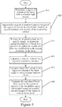
- operations begin at block 315 by illuminating a region of interest in the heart with a coherent light source.
- the coherent light source may have a wavelength of from about 600 nm to about 1100 nm.
- Providing a coherent light source with a wavelength of from about 600 nm to about 1100 nm may allow for non-invasive, deep penetration of light into tissues and provides an accurate determination of blood flow speed in the principal vessels and the perfusion distribution within the layer of light penetration.
- the coherent light source may be provided by a laser configured to illuminate the region of interest.
- the laser may have a fixed or variable wavelength.
- the laser may produce a beam having substantially constant intensity within a FOV of an imaging unit.
- the laser may be a low energy and continuous-wave laser such that the subject does not require any protective apparatus to shield the subject from effects of the laser.
- operations continue at block 325 by sequentially acquiring at least two speckle images of the region of interest during a fixed time period.
- the fixed time period may be selected based on data associated with in situ determined blood flow speed.
- the at least two speckle images are acquired in synchronization with motion of a heart of the subject such that the motion of the heart will have minimal effect on determination of blood flow speed using the acquired at least two speckle images.
- the fixed time period can correspond to a single EKG cardiac cycle or defined portion thereof cycle.
- the camera may be configured to acquire the at least two speckle images during the fixed time period.
- from about 50 to about 1000 speckle images may be acquired using the camera during the fixed time period of from about 1 ms to about 200 ms.
- about 200 to about 500 speckle images may be acquired.
- Higher numbers of speckle images typically allow better signal-to-noise ratios in the calculated LSCI image but take longer time to acquire.
- operations continue at block 335 by electronically processing the acquired speckle images based on the temporal variation of the pixel intensities in the acquired speckle images to generate a laser speckle contrast imaging (LSCI) image and determine spatial distribution of blood flow speed in the principal vessels and perfusion distribution in tissue in the region of interest from the LSCI image.
- LSCI laser speckle contrast imaging
- electronically evaluating speckle image data may include electronically evaluating the acquired speckle images using an image processing algorithm that combines temporal and spatial calculations of the acquired speckle images to generate a LSCI image and determine spatial distribution of blood flow speed.
- the at least two speckle images may have a direct relationship to the blood flow speed in the principal vessels and the perfusion distribution which are utilized in generating an LSCI image for determination of the spatial distribution of blood flow speed.
- blocks 315, 325 and 335 may be performed before and after a procedure performed on the subject.
- the results before and after the procedure may be compared to verify the success of the procedure in the subject.
- Operations begin at block 415 by illuminating a region of interest in the heart with a coherent light source, wherein the coherent light source has a wavelength of from about 600 nm to about 1100 nm.
- At least two speckle images of the region of interest are sequentially acquired during a fixed time period (block 425) in synchronization with the motion of the heart.
- Temporal and spatial variation of pixel intensities of the at least two acquired speckle images are electrically evaluated to determine spatial distribution of blood flow speed in the principal vessels and perfusion distribution in tissue in the region of interest of the heart(block 435).
- a velocity field for the region of interest in the heart is calculated (block 445).
- the velocity field is calculated using equations (9) and (10) set out below.
- Blood flow speed in the region of interest of the heart based on the calculated velocity field is calculated (block 455).
- the calculated blood flow speed in the region of interest in the heart is compared to the blood flow speed determined using the acquired at least two speckle images of the region of interest to verify results obtained using the at least two speckle images (block 465).
- embodiments of the present inventive concept may be used to verify experimental results as will be discussed further below.
- blocks 415, 425, 435, 445, 455 and 465 may be performed before and after a procedure performed on the subject.
- the results before and after the procedure may be compared to verify the success of the procedure in the subject.
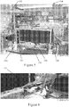
- the system includes a communication device 510, such as a laptop computer, a laser unit 520 including a laser generator and a focusing lens, a camera 530, a flow generator 580, flow liquid 590 and a flow target 585.
- a communication device 510 such as a laptop computer
- a laser unit 520 including a laser generator and a focusing lens
- a camera 530 a camera 530
- a flow generator 580 flow liquid 590
- flow target 585 a digital photograph of a prototype system 500 to detect flow speed using laser speckle contrast imaging
- the laser 520 is a low power continuous-wave laser providing a single-wavelength coherent light source.
- the subject of the imaging does not typically require any protection from such a laser, such as protective clothing or eyewear.
- the laser 520 produces a beam having a wavelength of from about 600nm to about 1100nm in some embodiments.
- the laser beam produced by the laser 520 is used to illuminate the region of interest with substantially constant intensity with the FOV of the imaging unit. This is an important aspect of the experiment because it allows the resulting images to have a high SNR.
- Colored intralipid was used as the flow liquid 590 during the experiment due to the fact that a light scattering characteristics of the colored intralipid is similar to those of mammalian blood. Thus, the colored intralipid mimics the blood flowing in the human body.
- the communications device 510 used was a laptop computer, although embodiments of the present inventive concept are not limited to the use of a laptop computer.
- the acquired speckle images are provided to the communications device 510 and are used to calculate blood flow in according with some embodiments of the present inventive concept. As discussed above, the data is calculated using an image processing algorithm that combines temporal and spatial calculations of the acquired speckle images. Thus, spatial distribution of blood flow speed in principal vessels and perfusion distribution can be determined.
- Figure 6 is a close up photograph of the laser unit 520
- Figure 7 is a close up photograph of the camera 530
- Figure 8 is a close up photograph of the communications device 510
- Figure 9 is a close of the flow liquid 590.
- Table 2 set out below summarizes parameters for the camera 530 used during the first experiment. The parameters are for the camera 530 while the image sequence is acquired. TABLE 2 Length of image sequence ⁇ 1 second Frame rate ⁇ 95 frames/second Image resolution 320*240 pixels Exposure time per frame 3 ms Gain 1
- V limit ⁇ L 10 ⁇
- ⁇ L the diameter of the tube, which was 0.26cm in the first experiment
- f the frame rate.
- V limit can be roughly estimated at about 9.0 cm/second.
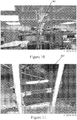
- Figure 10 illustrates the flow generation system 580.
- Figure 11 is a close up photograph of the tube target 585 used as the flow target for the first experiment.
- Table 3 summarizes the relationship between the change in height of the bottle and the flow of liquid in the flow generation system in accordance with the first experiment. The change in height is measured from the height of the bottle to the end of the tube.
- Figure 12 summarizes the data in Table 3 and is a graph illustrating delta height (cm) vs. flow rate (ml/min).
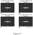
- Figure 13A is an averaged image obtained by averaging in a pixel-to-pixel fashion 97 frames for the "no flow” case
- Figure 13B is a vertical line profile image in the middle of inverted speckle contrast image for the "no flow” case
- Figure 13C is an inverted speckle contrast image for the "no flow” case
- Figure 13D is a colorized inverted speckle contrast image for the "no flow” case.
- Figures 14A through 14D illustrate resultant images obtained for the "flow 1" case.
- Figure 14A is an averaged image obtained by averaging in a pixel-to-pixel fashion 97 frames for the "flow 1" case;
- Figure 14B is a vertical line profile image in the middle of the inverted speckle contrast image for the "flow 1" case ;
- Figure14C is an inverted speckle contrast image for the "flow 1" case ;
- Figure 14D is a colorized inverted speckle contrast image for the "flow 1" case .
- Figures 15A through15D illustrate resultant images obtained for the "flow 2" case.
- Figure 15A is an averaged image obtained by averaging in a pixel-to-pixel fashion 89 frames for the "flow 2" case;
- Figure 15B is a vertical line profile image in the middle of an inverted speckle contrast image for the "flow 2" case ;
- Figure 15C is an inverted speckle contrast image for the "flow 2" case ;
- Figure 15D is a colorized inverted speckle contrast image for the "flow 2" case .
- Figures 16A through 16D illustrate resultant images obtained for the "flow 3" case.
- Figure 16A is an averaged image obtained by averaging in a pixel-to-pixel fashion 89 frames for the "flow 3" case;
- Figure 16B is a vertical line profile image in the middle of an inverted speckle contrast image for the "flow 3" case ;
- Figure 16C is an inverted speckle contrast image for the "flow 3” case ;
- Figure 16D is a colorized inverted speckle contrast image for the "flow 3" case .
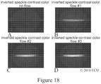
- Figures 17A through 17D are the averaged images for each of the cases , “no flow”, “flow 1", “flow 2", and “flow 3,” respectively.
- Figures 18A through 18D are colorized inverted speckle contrast images for each of the cases , “no flow”, “flow 1", “flow 2", and “flow 3,” respectively.
- Figures 19A through 19D are vertical line profile images for each of the cases, “no flow”, “flow 1", “flow 2", and “flow 3,” respectively.
- Figure 20 is a graph illustrating predicted flow rate (ml/min) vs. inverted speckle contrast image pixel intensity as set out in Table 4.
- TABLE 4 Status delta height (cm) predicted flow rate (ml/min) inverted speckle contrast image pixel intensity No flow 0 0 15 Flow 1 10 10.6 67 Flow 2 100 84.5 88 Flow 3 193 150.7 108
- the laser speckle contrast imaging setup is clearly able to differentiate between a no flow state and the three flow speed cases .
- the sensitivity and precision were not ideal and the point of "no flow" was not consistent with the other three flow points as illustrated in Figure 20 .
- Some of the imprecision may be due to using a bottle for the flow speed generation method. This may have caused variation and lack of constant flow.
- frame rate of the camera may have limited to number of speckle images that could be obtained.
- the laser beam intensity used during the experiment was uneven in the FOV, i.e. there are dark spots in the FOV.
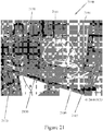
- the system includes a communications device 2110, such as a laptop computer, a laser unit 2120 including a laser generator and a beam shaping lens, a camera 2130, a flow generator 2181 provided by a biomedical pump, flow liquid 2190, a flow target 2185 and an electromagnetic flow detector 2191.
- a communications device 2110 such as a laptop computer
- a laser unit 2120 including a laser generator and a beam shaping lens
- a camera 2130 a flow generator 2181 provided by a biomedical pump
- flow liquid 2190 flow target 2185
- an electromagnetic flow detector 2191 an electromagnetic flow detector
- the laser 2120 is a low power laser providing a single coherent light source.
- the subject of the imaging does not typically require any protection from the laser, such as protective clothing or eyewear.
- the laser 2120 produces a beam having a wavelength of from about 600nm to about 1100nm in some embodiments.
- the laser beam produced by the laser 2120 is used to illuminate the region of interest with substantially constant intensity with the FOV of the imaging unit. This may allow the speckle contrast images to have a high signal-to-noise ratio.
- the communications device 2110 used was a laptop computer, although embodiments of the present inventive concept are not limited to the use of a laptop computer.
- the acquired speckle images are provided to the communications device 2110 and are used to calculate blood flow in according with some embodiments of the present inventive concept. As discussed above, the data are calculated using an image processing algorithm that combines temporal and spatial calculations of the acquired speckle images. Thus, spatial distribution of blood flow speed in principal vessels and perfusion distribution can be determined.
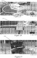
- Figure 22 is a close up photograph of the laser unit 2120;
- Figure 23 is a close up photograph of the camera 2130;
- Figure 24 is a close up photograph of the communications device 2110;
- Figure 25 is a close up photograph of the biomedical pump 2181;
- Figure 26 is a close up photograph of the electromagnetic flow detector 2191;
- Figure 27 is a close up photograph of the flow target 2185.
- Table 6 set out below summarizes parameters for the camera 530 used during the second experiment. The parameters are for the camera 2130 while the image sequence is acquired. TABLE 6 Length of image sequence ⁇ 1 second Frame rate ⁇ 95 frames/second Image resolution 320*240 Exposure time per frame 3 ms (split into 3 part to calculate std and average every 3 continuous frames) Gain 1 Working distance ⁇ 1.5 m Aperture 2 ⁇ 4 Length of the video loop 3* 1 second
- the biomedical pump was calibrated by comparing measured liquid volume during a certain time with the reading from the electromagnetic flow detector 2591 as illustrated in Table 8 set out below.
- pump calibration using 20% Intralipid solution mixed by saline water with 1:4 ratio volume was measured from 100mL to 300mL and reading from the detector was recorded when liquid reaches 200mL.
- L 0 is an added term to account for background noise and should be zero after the baseline has been removed
- ⁇ is a constant related to the imaging parameters, laser parameters, time/spatial smoothing parameters for obtaining K and the components of the liquid;
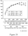
- Figure 29 is a graph illustrating flow speed vs. the L with curve fitting based on Equation (8).
- the experiment showed that the inverted speckle image pixel intensity L acquired with the current imaging system can correlate to the speed of the flow within certain range, (flow speed ⁇ 800 cm/min or LAD flow rate ⁇ 100 mL/min), which corresponds to the maximum blood flow rate in average main branch of coronary artery.
- flow speed ⁇ 800 cm/min or LAD flow rate ⁇ 100 mL/min corresponds to the maximum blood flow rate in average main branch of coronary artery.
- ⁇ 633
- Figure 33 is a digital photograph of a prototype system setup used to detect blood flow speed using the LSCI technology in accordance with some embodiments of the present inventive concept.
- the experiment discussed with respect to Figures 33 through 43 is similar to the experiment discussed above with respect to Figures 21 through 32 , but an extra reservoir 3397 is present to add red blood cells into the circulation from a blood bag 3398 (expired and for research use only), which is acquired from the Red Cross. Thus, many of the details of the experiment will not be repeated herein.
- Table 15 set out below summarizes parameters for the camera used during the second experiment. The parameters are for the camera while the image sequence is acquired. TABLE 15 Length of image sequence 1 second Frame rate ⁇ 95 frames/second Image resolution 320*240 Exposure time per frame 3 ms Gain 1 working distance 1.5 ⁇ 4 m Aperture 2 Length of the video loop 3*1 second (split into 3 part to calculate std and average every 3 continuous frames)
- Figures 34A through 34D illustrate resultant images obtained for the "tube is clamped” case.
- Figure 34A is an averaged image of 90 frames for the "tube is clamped” case;
- Figure 34B is a vertical line profile image in the middle of inverted speckle contrast image for the "tube is clamped” case;
- Figure 34C is an inverted speckle contrast image for the "tube is clamped” case;
- Figure 34D is a false-color inverted speckle contrast image for the "tube is clamped” case.
- Figures 35A through 35D illustrate resultant images obtained for the "pump reads 100mL” case.
- Figure 35A is an averaged image of 97 frames for the "100mL” case;
- Figure 35B is a vertical line profile in the middle of an inverted speckle contrast image for the "100mL” case;
- Figure35C is a n inverted speckle contrast image for the "100mL” case;
- Figure 35D is a false-color inverted speckle contrast image for the "100mL” case.
- Figures 36A through36D illustrate resultant images obtained for the "pump reads 500mL” case.
- Figure 36A is an averaged image of 97 frames for the "500mL” case;
- Figure 36B is a vertical line profile image in the middle of an inverted speckle contrast image for the "500mL” case;
- Figure 36C is a n inverted speckle contrast image for the "500mL” case;
- Figure 36D is a false-color speckle contrast image for the "500mL” case.
- Figures 37A through 37D illustrate resultant images obtained for the "pump reads 1000mL” case.
- Figure 37A is an averaged image of 98 frames for the "1000mL” case;
- Figure 37B is a vertical line profile image in middle of an inverted speckle contrast image for the "1000mL” case;
- Figure 37C is an inverted speckle contrast image for the "1000mL” case;
- Figure 37D is a false-color inverted speckle contrast image for the "1000mL” case.
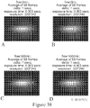
- Figures 38A through 38D are averaged images for each of the cases, “pump clamped”, “100mL”, “500mL”, and “1000mL,” respectively.
- Figures 39A through 39D are colorized inverted speckle contrast images for each of the cases, “pump clamped”, “100mL”, “500mL”, and “1000mL,” respectively.
- Figures 40A through 40D are vertical line profile images for each of the cases, “pump clamped”, “100mL”, “500mL", and "1000mL,” respectively.
- the laser speckle imaging setup illustrated in Figure 33 is clearly able to differentiate different flow speeds of human blood.
- the LSCI image still has contrast related to flow speed as illustrated in Figures 43A through 43D .
- the contrast disappears as shown in Figures 44A through 44D .
- the power of the speed term v in Equation (8) after curve fitting was found not equal to 0.5, which is different from the Intralipid solution as discussed above with respect to Figures 21-32 .
- ⁇ is the density (kg/m 3 )
- u is the velocity vector (m/s)
- p is the pressure (N N/m 2 or Pascal)
- F the volume force vector (N/m 3 )
- ⁇ the viscosity
- these quantities may be calculated before a procedure is performed on a subject and after a procedure is performed on the subject to verify that the procedure was successful.
- measurements, images and calculations discussed above may be performed before a subject undergoes a carotid endarterectomy (CEA), which is a surgical procedure used to reduce the likelihood, or possibly prevent stroke, by correcting stenosis (narrowing) in the common carotid artery.
- CCA carotid endarterectomy
- Endarterectomy is the removal of material on the inside ( end -) of an artery.
- a blood vessel 4501 including a narrowing 4597 is illustrated, for example, in Figure 45 .
- a velocity field/profile may be calculated at various point in the blood vessel as illustrated in Figure 46 before and after the carotid endarterectomy to correct the narrowing 4597.
- Figure 47 is a graph illustrating fluid rate estimate along the diameter of the blood vessel 4501 illustrated in Figures 45 and 46 .
- embodiments of the present inventive concept are not limited to this configuration.
- embodiments of the present inventive concept may be used for the brain, colon, or any other applicable part of the subject that may benefit from the techniques discussed herein.
- Operations for a non-invasive method for measuring blood flow in principal vessels of a subject in accordance with some embodiments will be discussed with respect to Figure 48 .
- Operations begin at block 4816 by illuminating a region of interest with a coherent light source, wherein the coherent light source has a wavelength of from about 600 nm to about 1100 nm.
- At least two speckle images of the region of interest are sequentially acquired during a fixed time period (block 4826).
- Temporal and spatial variation of pixel intensities of the at least two acquired speckle images are electrically evaluated to determine spatial distribution of blood flow speed in the principal vessels and perfusion distribution in tissue in the region of interest (block 4836).
- a velocity field for the region of interest is calculated (block 4846).
- the velocity field is calculated using equations (9) and (10) set out below.
- Blood flow speed in the region of interest based on the calculated velocity field is calculated (block 4856).
- the calculated blood flow speed in the region of interest is compared to the blood flow speed determined using the acquired at least two speckle images of the region of interest to verify results obtained using the at least two speckle images (block 4866).
- embodiments of the present inventive concept may be used to verify experimental results as will be discussed further below.
- blocks 4816, 4826, 4836, 4846, 4856 and 4866 may be performed before and after a procedure performed on the subject.
- the results before and after the procedure may be compared to verify the success of the procedure in the subject.
Landscapes
- Health & Medical Sciences (AREA)
- Life Sciences & Earth Sciences (AREA)
- Physics & Mathematics (AREA)
- Engineering & Computer Science (AREA)
- General Health & Medical Sciences (AREA)
- Medical Informatics (AREA)
- Molecular Biology (AREA)
- Public Health (AREA)
- Biophysics (AREA)
- Biomedical Technology (AREA)
- Heart & Thoracic Surgery (AREA)
- Veterinary Medicine (AREA)
- Pathology (AREA)
- Surgery (AREA)
- Animal Behavior & Ethology (AREA)
- Cardiology (AREA)
- Physiology (AREA)
- General Physics & Mathematics (AREA)
- Hematology (AREA)
- Vascular Medicine (AREA)
- Optics & Photonics (AREA)
- Nuclear Medicine, Radiotherapy & Molecular Imaging (AREA)
- Radiology & Medical Imaging (AREA)
- Quality & Reliability (AREA)
- Computer Vision & Pattern Recognition (AREA)
- Theoretical Computer Science (AREA)
- Measuring Pulse, Heart Rate, Blood Pressure Or Blood Flow (AREA)
Claims (14)
- Procédé non invasif pour mesurer un écoulement sanguin dans des vaisseaux principaux d'un cœur d'un sujet, le procédé comprenant :éclairer une région d'intérêt (140) dans le cœur avec une source de lumière cohérente (120), la source de lumière cohérente (120) ayant une longueur d'onde allant d'environ 600 nm à environ 1100 nm ;acquérir séquentiellement au moins deux images à granulation cohérente d'une région d'intérêt dans le cœur pendant une période de temps fixe, l'acquisition séquentielle des au moins deux images à granulation cohérente comprenant l'acquisition des au moins deux images à granulation cohérente en synchronisation avec un mouvement du cœur du sujet ; ettraiter électroniquement les au moins deux images à granulation cohérente acquises sur la base d'une variation temporelle d'intensités de pixel dans les au moins deux images à granulation cohérente acquises pour générer une image d'imagerie de contraste à granulation cohérente laser (LSCI) et déterminer une distribution spatiale d'une vitesse d'écoulement sanguin dans les vaisseaux principaux et quantifier une distribution de perfusion dans un tissu dans la région d'intérêt dans le cœur à partir de l'image de LSCI.
- Procédé selon la revendication 1, dans lequel l'acquisition séquentielle des au moins deux images à granulation cohérente qui comprend l'acquisition des au moins deux images à granulation cohérente en synchronisation avec un mouvement du cœur du sujet comprend en outre :surveiller électroniquement un cycle cardiaque ECG du sujet ; etsynchroniser électroniquement l'acquisition des images à granulation cohérente avec des signaux ECG.
- Procédé selon l'une quelconque des revendications précédentes, comprenant en outre :calculer un débit sanguin dans la région d'intérêt dans le cœur sur la base d'un champ de vitesse calculé ; etcomparer le débit sanguin calculé dans la région d'intérêt à la vitesse d'écoulement sanguin déterminée à l'aide des au moins deux images à granulation cohérente acquises de la région d'intérêt dans le cœur pour vérifier des résultats obtenus à l'aide des au moins deux images à granulation cohérente.
- Procédé selon la revendication 3, dans lequel le champ de vitesse et le débit sont calculés sur la base des équations suivantes avec des conditions limites et initiales appropriées :


- Procédé selon l'une quelconque des revendications précédentes, dans lequel la source de lumière cohérente (120) a une longueur d'onde allant d'environ 600 nm à environ 1100 nm et permet une pénétration relativement profonde de lumière dans des tissus pour ainsi permettre une détermination précise d'une vitesse d'écoulement sanguin dans les vaisseaux principaux et de la distribution de perfusion sous la surface.
- Procédé selon l'une quelconque des revendications précédentes, dans lequel la source de lumière cohérente (120) comprend un laser (123) configuré pour éclairer la région d'intérêt (140) avec une intensité sensiblement constante.
- Procédé selon la revendication 6, dans lequel le laser (123) a une longueur d'onde fixe ou variable allant d'environ 600 nm à environ 1100 nm.
- Procédé selon la revendication 6, dans lequel le laser (123) génère un faisceau de sortie ayant une intensité sensiblement constante dans un champ de vision (FOV) d'une unité d'imagerie (130).
- Procédé selon la revendication 6, dans lequel le laser (123) comprend un laser à faible puissance et à onde continue (123) de telle sorte que le sujet ne nécessite pas d'appareil de protection pour protéger le sujet contre des effets du laser.
- Procédé selon la revendication 6 :dans lequel le laser (123) produit un seul faisceau lumineux d'une longueur d'onde comprise dans une région spectrale allant de l'ultraviolet à l'infrarouge ;dans lequel l'acquisition séquentielle comprend l'acquisition séquentielle d'environ 50 à environ 1000 images à granulation cohérente comme étant les au moins deux images à granulation cohérente à l'aide d'une caméra (130) pendant la période de temps fixe allant d'environ 1 ms à environ 200 ms ; etdans lequel l'acquisition séquentielle comprend l'acquisition d'environ 200 à environ 500 images à granulation cohérente pendant la période de temps fixe.
- Procédé selon la revendication 10, dans lequel la période de temps fixe est sélectionnée sur la base d'une acquisition in situ d'une vitesse d'écoulement sanguin du sujet dans la région d'intérêt.
- Système non invasif (100) pour mesurer un écoulement sanguin dans des vaisseaux principaux dans un cœur d'un sujet, le système comprenant :une source de lumière cohérente (120) configurée pour éclairer une région d'intérêt (140) dans le cœur du sujet, la source de lumière cohérente ayant une longueur d'onde allant d'environ 600 nm à environ 1100 nm ;une caméra en communication avec la source de lumière cohérente qui est configurée pour acquérir séquentiellement au moins deux images à granulation cohérente de la région d'intérêt dans le cœur pendant une période de temps fixe, l'acquisition des au moins deux images à granulation cohérente étant synchronisée avec un mouvement du cœur du sujet ; etun circuit de traitement de données (200) configuré pour évaluer une variation temporelle d'intensités de pixel dans les au moins deux images à granulation cohérente acquises pour générer une image d'imagerie de contraste à granulation cohérente laser (LSCI) et déterminer une distribution spatiale d'une vitesse d'écoulement sanguin dans les vaisseaux principaux et quantifier une distribution de perfusion dans un tissu dans la région d'intérêt dans le cœur à partir de l'image de LSCI.
- Système selon la revendication 12 :dans lequel le circuit de traitement de données (200) est en outre configuré pour :surveiller électroniquement un cycle cardiaque ECG du sujet ; etsynchroniser électroniquement l'acquisition des images à granulation cohérente avec des signaux ECG ; etdans lequel le système comprend en outre un module de modélisation (354) configuré pour :calculer un champ de vitesse pour la région d'intérêt dans le cœur ;calculer un débit sanguin dans la région d'intérêt dans le cœur sur la base du champ de vitesse calculé ; etcomparer le débit sanguin calculé dans la région d'intérêt à la vitesse d'écoulement sanguin déterminée à l'aide des au moins deux images à granulation cohérente acquises de la région d'intérêt dans le cœur pour vérifier des résultats obtenus à l'aide des au moins deux images à granulation cohérente.
- Système selon la revendication 13, dans lequel le module de modélisation (354) est configuré pour calculer le champ de vitesse et le débit sanguin sur la base des équations suivantes avec des conditions limites et initiales appropriées :


Applications Claiming Priority (3)
| Application Number | Priority Date | Filing Date | Title |
|---|---|---|---|
| US201161431161P | 2011-01-10 | 2011-01-10 | |
| US201161476854P | 2011-04-19 | 2011-04-19 | |
| PCT/US2012/020626 WO2012096878A2 (fr) | 2011-01-10 | 2012-01-09 | Procédés, systèmes et produits programmes d'ordinateur pour une détermination non effractive de distribution du flux sanguin à l'aide de techniques d'imagerie à tachetures et modélisation hémodynamique |
Publications (2)
| Publication Number | Publication Date |
|---|---|
| EP2663222A2 EP2663222A2 (fr) | 2013-11-20 |
| EP2663222B1 true EP2663222B1 (fr) | 2021-10-27 |
Family
ID=45529226
Family Applications (1)
| Application Number | Title | Priority Date | Filing Date |
|---|---|---|---|
| EP12701039.5A Active EP2663222B1 (fr) | 2011-01-10 | 2012-01-09 | Procédés et systèmes pour une détermination non effractive de distribution du flux sanguin à l'aide de techniques d'imagerie à tachetures et modélisation hémodynamique |
Country Status (4)
| Country | Link |
|---|---|
| US (1) | US9271658B2 (fr) |
| EP (1) | EP2663222B1 (fr) |
| CA (1) | CA2824134C (fr) |
| WO (1) | WO2012096878A2 (fr) |
Families Citing this family (44)
| Publication number | Priority date | Publication date | Assignee | Title |
|---|---|---|---|---|
| US20070122344A1 (en) | 2005-09-02 | 2007-05-31 | University Of Rochester Medical Center Office Of Technology Transfer | Intraoperative determination of nerve location |
| US20080161744A1 (en) | 2006-09-07 | 2008-07-03 | University Of Rochester Medical Center | Pre-And Intra-Operative Localization of Penile Sentinel Nodes |
| US8406860B2 (en) | 2008-01-25 | 2013-03-26 | Novadaq Technologies Inc. | Method for evaluating blush in myocardial tissue |
| US10219742B2 (en) | 2008-04-14 | 2019-03-05 | Novadaq Technologies ULC | Locating and analyzing perforator flaps for plastic and reconstructive surgery |
| EP2687235A3 (fr) | 2008-05-02 | 2014-11-05 | Novadaq Technologies Inc. | Procédés de production et d'utilisation d'érythrocytes chargés de substance (S-LES) pour l'observation et le traitement de l'hémodynamique vasculaire |
| EP2309919B1 (fr) | 2008-07-10 | 2019-03-06 | Ecole Polytechnique Federale De Lausanne (EPFL) EPFL-TTO | Imagerie optique cohérente fonctionnelle |
| US10492671B2 (en) | 2009-05-08 | 2019-12-03 | Novadaq Technologies ULC | Near infra red fluorescence imaging for visualization of blood vessels during endoscopic harvest |
| US9226673B2 (en) * | 2011-01-10 | 2016-01-05 | East Carolina University | Methods, systems and computer program products for non-invasive determination of blood flow distribution using speckle imaging techniques and hemodynamic modeling |
| US9271658B2 (en) | 2011-01-10 | 2016-03-01 | East Carolina University | Methods, systems and computer program products for non-invasive determination of blood flow distribution using speckle imaging techniques and hemodynamic modeling |
| JP5977440B2 (ja) | 2012-04-27 | 2016-08-24 | アイマゴ ソシエテ アノニムAimago S.A. | 光コヒーレントイメージング医療デバイス |
| WO2013190391A2 (fr) | 2012-06-21 | 2013-12-27 | Novadaq Technologies Inc. | Quantification et analyse d'angiographie et de perfusion |
| JP6023883B2 (ja) | 2012-07-10 | 2016-11-09 | アイマゴ ソシエテ アノニムAimago S.A. | 灌流評価マルチモダリティ光学医用デバイス |
| JP6076111B2 (ja) * | 2013-02-07 | 2017-02-08 | 浜松ホトニクス株式会社 | 塊状細胞評価方法および塊状細胞評価装置 |
| EP3145397A4 (fr) * | 2014-05-23 | 2018-01-17 | Covidien LP | Systèmes permettant l'imagerie de circulation sanguine en laparoscopie |
| US10178959B1 (en) | 2014-07-10 | 2019-01-15 | Verily Life Sciences Llc | Non-invasive flow monitoring |
| US10206576B2 (en) | 2014-09-10 | 2019-02-19 | Samsung Electronics Co., Ltd. | Laser speckle interferometric system and method for mobile devices |
| KR102068776B1 (ko) | 2014-09-29 | 2020-01-21 | 노바다크 테크놀러지즈 유엘씨 | 자가형광이 존재하는 생물학적 물질에서 타겟 형광체의 이미징 |
| JP6487544B2 (ja) | 2014-10-09 | 2019-03-20 | ノバダック テクノロジーズ ユーエルシー | 蛍光媒介光電式容積脈波記録法を用いた組織中の絶対血流の定量化 |
| US11553844B2 (en) * | 2014-10-14 | 2023-01-17 | East Carolina University | Methods, systems and computer program products for calculating MetaKG signals for regions having multiple sets of optical characteristics |
| JP6813245B2 (ja) | 2014-10-14 | 2021-01-13 | イースト カロライナ ユニバーシティ | 単一の画像上で解剖学的データと生理学的データとを結合するためのシステムの作動方法、コンピュータシステム、及び単一の画像上で解剖学的データと生理学的データとを結合するためのプログラムが記録された記録媒体 |
| CA2963866C (fr) | 2014-10-14 | 2023-11-07 | East Carolina University | Procedes, systemes et produits de programme informatique pour determiner des parametres d'etat hemodynamique au moyen de signaux derives d'imagerie multispectrale de circulation e t perfusion sanguine |
| US9931040B2 (en) * | 2015-01-14 | 2018-04-03 | Verily Life Sciences Llc | Applications of hyperspectral laser speckle imaging |
| US10390718B2 (en) | 2015-03-20 | 2019-08-27 | East Carolina University | Multi-spectral physiologic visualization (MSPV) using laser imaging methods and systems for blood flow and perfusion imaging and quantification in an endoscopic design |
| US10058256B2 (en) | 2015-03-20 | 2018-08-28 | East Carolina University | Multi-spectral laser imaging (MSLI) methods and systems for blood flow and perfusion imaging and quantification |
| EP3291725A4 (fr) | 2015-05-07 | 2018-11-07 | Novadaq Technologies Inc. | Procédés et systèmes pour une imagerie laser à granularité de tissu à l'aide d'un capteur d'image couleur |
| IL239113A (en) | 2015-06-01 | 2016-12-29 | Elbit Systems Land & C4I Ltd | A system and method for determining audio characteristics from a body |
| GB2548626A (en) | 2016-03-24 | 2017-09-27 | Imp Innovations Ltd | A method and an apparatus for determining haemodynamic status |
| EP3440997B1 (fr) * | 2016-04-05 | 2020-11-25 | Sony Corporation | Dispositif de mesure du chatoiement et procédé de mesure du chatoiement |
| CN106419890B (zh) * | 2016-11-14 | 2024-04-30 | 佛山科学技术学院 | 一种基于时空调制的血流速度测量装置及方法 |
| US11589801B2 (en) | 2016-12-27 | 2023-02-28 | Vanderbilt University | Methods and apparatus for intraoperative assessment of parathyroid gland vascularity using laser speckle contrast imaging and applications of same |
| EP3562386A4 (fr) * | 2016-12-29 | 2020-08-26 | Vanderbilt University | Procédés et appareil d'évaluation peropératoire de la vascularité de la glande parathyroïde à l'aide d'une imagerie par contraste de granularité laser et leurs applications |
| EP3580609B1 (fr) | 2017-02-10 | 2023-05-24 | Stryker European Operations Limited | Systèmes et procédés d'imagerie à fluorescence portative à champ ouvert |
| CN108523872A (zh) * | 2017-03-06 | 2018-09-14 | 上海健康医学院 | 一种理疗功效评估方法及系统 |
| JP2021526907A (ja) | 2018-06-08 | 2021-10-11 | イースト カロライナ ユニバーシティ | マルチスペクトルレーザ撮像(MSLI)方法及びシステムを使用した末梢血酸素飽和度(SpO2)及びヘモグロビン濃度の決定 |
| MX2021000628A (es) | 2018-07-16 | 2021-05-27 | Bbi Medical Innovations Llc | Medicion de perfusion y oxigenacion. |
| JP7297891B2 (ja) | 2018-07-19 | 2023-06-26 | アクティブ サージカル, インコーポレイテッド | 自動化された外科手術ロボットのためのビジョンシステム内の深度のマルチモード感知のためのシステムおよび方法 |
| WO2020081159A2 (fr) | 2018-09-05 | 2020-04-23 | East Carolina University | Systèmes de détection de maladie vasculaire et artérielle chez des patients asymptomatiques et méthodes associées |
| WO2020081651A1 (fr) | 2018-10-16 | 2020-04-23 | Activ Surgical, Inc. | Procédés et systèmes autonomes pour attacher des nœuds chirurgicaux |
| WO2020198315A1 (fr) | 2019-03-26 | 2020-10-01 | East Carolina University | Imagerie par fluorescence proche infrarouge pour la visualisation de l'irrigation et du débit sanguins, ainsi que systèmes et produits programmes d'ordinateur associés |
| CN113950279B (zh) | 2019-04-08 | 2023-04-14 | 艾科缇弗外科公司 | 用于医疗成像的系统和方法 |
| CN114599263A (zh) | 2019-08-21 | 2022-06-07 | 艾科缇弗外科公司 | 用于医疗成像的系统和方法 |
| US20210128054A1 (en) * | 2019-10-31 | 2021-05-06 | Inthesmart Co., Ltd. | Apparatus and Method for Viability Assessment of Tissue |
| CN110974205B (zh) * | 2019-12-20 | 2022-04-22 | 华中科技大学苏州脑空间信息研究院 | 大视场多模态成像系统 |
| CN111696687B (zh) * | 2020-07-24 | 2022-03-25 | 上海理工大学 | 一种采用手机摄像头实现微循环及脉搏同步监测的方法 |
Citations (2)
| Publication number | Priority date | Publication date | Assignee | Title |
|---|---|---|---|---|
| WO2010004365A1 (fr) * | 2008-07-10 | 2010-01-14 | Ecole Polytechnique Federale De Lausanne (Epfl) | Imagerie optique cohérente fonctionnelle |
| WO2010096447A2 (fr) * | 2009-02-17 | 2010-08-26 | Board Of Regents, The University Of Texas System | Imagerie quantitative avec imagerie par speckle à expositions multiples (mesi) |
Family Cites Families (50)
| Publication number | Priority date | Publication date | Assignee | Title |
|---|---|---|---|---|
| US4541433A (en) | 1984-06-01 | 1985-09-17 | Medtronic, Inc. | Cardiac output monitor |
| DE69011158T2 (de) | 1989-03-06 | 1995-01-12 | Kowa Co | Gerät zur Diagnostik in der Augenheilkunde. |
| DE69017249T2 (de) | 1989-04-10 | 1995-08-03 | Kowa Co | Ophthalmologisches Messverfahren und Einrichtung. |
| JPH02268727A (ja) | 1989-04-10 | 1990-11-02 | Kowa Co | 眼科測定方法及び装置 |
| JPH0428348A (ja) | 1990-05-24 | 1992-01-30 | Hitoshi Fujii | 血流状態画像化装置 |
| US5161531A (en) | 1990-09-14 | 1992-11-10 | Duke University | Method and apparatus for intravascularly measuring oxidative metabolism in body organs and tissues |
| JP3021628B2 (ja) | 1990-11-27 | 2000-03-15 | 興和株式会社 | 血流測定装置 |
| JP3035336B2 (ja) | 1990-11-27 | 2000-04-24 | 興和株式会社 | 血流測定装置 |
| DE19506484C2 (de) | 1995-02-24 | 1999-09-16 | Stiftung Fuer Lasertechnologie | Verfahren und Vorrichtung zur selektiven nichtinvasiven Lasermyographie (LMG) |
| US5860922A (en) | 1995-09-07 | 1999-01-19 | Technion Research And Development Foundation Ltd. | Determining blood flow by measurement of temperature |
| US5692510A (en) | 1995-09-07 | 1997-12-02 | Technion Research And Development Foundation Ltd. | Determining coronary blood flow by cardiac thermography in open chest conditions |
| US5588436A (en) | 1995-10-11 | 1996-12-31 | Cook Pacemaker Corporation | Pulsed doppler probe |
| JPH10290791A (ja) | 1997-04-18 | 1998-11-04 | Advance Co Ltd | レーザー血流計 |
| US20050182434A1 (en) | 2000-08-11 | 2005-08-18 | National Research Council Of Canada | Method and apparatus for performing intra-operative angiography |
| US6915154B1 (en) | 1999-09-24 | 2005-07-05 | National Research Council Of Canada | Method and apparatus for performing intra-operative angiography |
| US6458086B1 (en) | 2000-04-05 | 2002-10-01 | Kenneth Lawrence Franco | Implantable blood flow monitoring system |
| WO2002013688A2 (fr) | 2000-08-16 | 2002-02-21 | Cook Vascular Incorporated | Sonde doppler possedant une partie modelable |
| US6537223B1 (en) | 2000-09-05 | 2003-03-25 | Medi-Stim As | Probe head |
| DE60141090D1 (de) | 2000-10-30 | 2010-03-04 | Gen Hospital Corp | Optische systeme zur gewebeanalyse |
| DE10059070C1 (de) | 2000-11-28 | 2002-02-14 | Pulsion Medical Sys Ag | Vorrichtung zur Bestimmung von Gewebeperfusion und intraoperative Verwendung |
| JP5076203B2 (ja) | 2001-06-21 | 2012-11-21 | 学校法人日本大学 | 血管疾患検査装置およびバイパス血管診断装置 |
| DE60139403D1 (de) | 2001-10-02 | 2009-09-10 | B K Medical As | Verfahren und Vorrichtung zur Geschwindigkeitsschätzung bei synthetischer Aperturabbildung |
| US7113817B1 (en) | 2001-10-04 | 2006-09-26 | Wintec, Llc | Optical imaging of blood circulation velocities |
| WO2003032808A2 (fr) | 2001-10-15 | 2003-04-24 | University Of Massachusetts | Systeme de mesure de l'oxygene dans les tissus |
| CA2413483A1 (fr) | 2001-12-26 | 2003-06-26 | Kevin R. Forrester | Dispositif de mesure du mouvement |
| EP1332718A1 (fr) | 2002-02-01 | 2003-08-06 | Stichting Voor De Technische Wetenschappen | Imagerie de perfusion par laser à effet Doppler avec un capteur d'image CMOS |
| US6922580B2 (en) | 2002-06-04 | 2005-07-26 | Koninklijke Philips Electronics N.V. | Blood flow gated MRI |
| US7404640B2 (en) | 2002-06-14 | 2008-07-29 | Physical Sciences, Inc. | Monitoring blood flow in the retina using a line-scanning laser ophthalmoscope |
| JP3490433B1 (ja) | 2003-06-02 | 2004-01-26 | 株式会社サイバーファーム | 生体情報監視システム |
| KR100634499B1 (ko) | 2004-01-12 | 2006-10-13 | 삼성전자주식회사 | 생체광자 측정을 통한 혈류 측정 장치 및 방법 |
| JP4995720B2 (ja) | 2004-07-02 | 2012-08-08 | ザ ジェネラル ホスピタル コーポレイション | ダブルクラッドファイバを有する内視鏡撮像プローブ |
| WO2006021096A1 (fr) * | 2004-08-23 | 2006-03-02 | Robarts Research Institute | Determination de parametres hemodynamiques |
| JP4649147B2 (ja) | 2004-08-31 | 2011-03-09 | 株式会社東芝 | 超音波診断装置 |
| EP1858404B1 (fr) | 2005-02-10 | 2010-04-14 | Koninklijke Philips Electronics N.V. | Detecteur de debit sanguin |
| JP4767551B2 (ja) * | 2005-02-14 | 2011-09-07 | セイコーインスツル株式会社 | 血液レオロジー測定装置および血液レオロジー計測方法 |
| WO2006111909A1 (fr) * | 2005-04-20 | 2006-10-26 | Cvl Cosmetics S.A. | Instrument et procede de visualisation de perfusion a haute vitesse |
| JPWO2007080743A1 (ja) * | 2006-01-16 | 2009-06-11 | 国立大学法人 北海道大学 | 検査システムおよび検査方法 |
| US7468039B2 (en) | 2006-06-02 | 2008-12-23 | Cook Vascular Incorporated | Adjustable tension cuff assembly |
| JP2010508056A (ja) | 2006-10-30 | 2010-03-18 | エルフィ−テック リミテッド | 生物学的パラメータの体内での測定のためのシステム及び方法 |
| US20100056936A1 (en) | 2006-12-01 | 2010-03-04 | Hitoshi Fujii | Blood flow rate imaging device |
| US10534129B2 (en) | 2007-03-30 | 2020-01-14 | The General Hospital Corporation | System and method providing intracoronary laser speckle imaging for the detection of vulnerable plaque |
| US7541602B2 (en) | 2007-06-04 | 2009-06-02 | Or-Nim Medical Ltd. | System and method for noninvasively monitoring conditions of a subject |
| CN101784227B (zh) * | 2007-07-06 | 2013-12-04 | 工业研究有限公司 | 激光散斑成像系统和方法 |
| JP5322548B2 (ja) | 2008-09-17 | 2013-10-23 | 株式会社東芝 | X線ct装置、医用画像処理装置および医用画像処理プログラム |
| WO2010096453A1 (fr) | 2009-02-17 | 2010-08-26 | Board Of Regents, The University Of Texas System | Procédés de production d'images de contraste à granularité laser |
| WO2010131550A1 (fr) | 2009-05-13 | 2010-11-18 | 国立大学法人九州工業大学 | Dispositif de diagnostic d'image de flux sanguin |
| CN102018511A (zh) | 2009-09-18 | 2011-04-20 | 株式会社东芝 | 磁共振成像装置以及磁共振成像方法 |
| JP5689662B2 (ja) | 2009-12-09 | 2015-03-25 | 株式会社東芝 | 超音波診断装置、超音波画像処理装置、超音波画像処理プログラム、医用画像診断装置、医用画像処理装置及び医用画像処理プログラム |
| EP2632324A4 (fr) * | 2010-10-27 | 2015-04-22 | Gen Hospital Corp | Appareil, systèmes et méthodes de mesure de la pression sanguine dans au moins un vaisseau |
| US9271658B2 (en) | 2011-01-10 | 2016-03-01 | East Carolina University | Methods, systems and computer program products for non-invasive determination of blood flow distribution using speckle imaging techniques and hemodynamic modeling |
-
2012
- 2012-01-09 US US13/819,817 patent/US9271658B2/en active Active
- 2012-01-09 EP EP12701039.5A patent/EP2663222B1/fr active Active
- 2012-01-09 CA CA2824134A patent/CA2824134C/fr active Active
- 2012-01-09 WO PCT/US2012/020626 patent/WO2012096878A2/fr active Application Filing
Patent Citations (4)
| Publication number | Priority date | Publication date | Assignee | Title |
|---|---|---|---|---|
| WO2010004365A1 (fr) * | 2008-07-10 | 2010-01-14 | Ecole Polytechnique Federale De Lausanne (Epfl) | Imagerie optique cohérente fonctionnelle |
| US20110169978A1 (en) * | 2008-07-10 | 2011-07-14 | Ecole Polytechnique Federale De Lausanne (Epfl) | Functional optical coherent imaging |
| WO2010096447A2 (fr) * | 2009-02-17 | 2010-08-26 | Board Of Regents, The University Of Texas System | Imagerie quantitative avec imagerie par speckle à expositions multiples (mesi) |
| US20120095354A1 (en) * | 2009-02-17 | 2012-04-19 | Andrew Dunn | Quantitative imaging with multi-exposure speckle imaging (mesi) |
Also Published As
| Publication number | Publication date |
|---|---|
| CA2824134C (fr) | 2019-05-14 |
| CA2824134A1 (fr) | 2012-07-19 |
| US9271658B2 (en) | 2016-03-01 |
| WO2012096878A2 (fr) | 2012-07-19 |
| US20130223705A1 (en) | 2013-08-29 |
| EP2663222A2 (fr) | 2013-11-20 |
| WO2012096878A3 (fr) | 2012-09-07 |
Similar Documents
| Publication | Publication Date | Title |
|---|---|---|
| EP2663222B1 (fr) | Procédés et systèmes pour une détermination non effractive de distribution du flux sanguin à l'aide de techniques d'imagerie à tachetures et modélisation hémodynamique | |
| EP2967380B1 (fr) | Procédés, systèmes et produits programmes d'ordinateur permettant de déterminer de manière non invasive la distribution du flux sanguin à l'aide de techniques d'imagerie par tavelures et par modélisation hémodynamique | |
| US20210106237A1 (en) | Method and system for image processing of intravascular hemodynamics | |
| Gagnon et al. | Quantification of the cortical contribution to the NIRS signal over the motor cortex using concurrent NIRS-fMRI measurements | |
| Gagnon et al. | Modeling of cerebral oxygen transport based on in vivo microscopic imaging of microvascular network structure, blood flow, and oxygenation | |
| US9538926B2 (en) | Speckle contrast optical tomography | |
| CA2740602C (fr) | Systemes d'imagerie offrant une compensation de guidage d'onde | |
| US20030211036A1 (en) | Method and apparatus for monitoring and quantitatively evaluating tumor perfusion | |
| Sakuma et al. | MR measurement of coronary blood flow | |
| Aminfar et al. | Application of optical flow algorithms to laser speckle imaging | |
| Wang et al. | Assessment of optical clearing induced improvement of laser speckle contrast imaging | |
| Rasulo et al. | Cerebral blood flow monitoring | |
| Gramer et al. | Device for simultaneous positron emission tomography, laser speckle imaging and RGB reflectometry: validation and application to cortical spreading depression and brain ischemia in rats | |
| Wang et al. | Comparison of the strain field of abdominal aortic aneurysm measured by magnetic resonance imaging and stereovision: A feasibility study for prediction of the risk of rupture of aortic abdominal aneurysm | |
| Krishnamurthi et al. | Functional imaging in small animals using X-ray computed tomography-study of physiologic measurement reproducibility | |
| Sethuraman | Cerebral blood flow monitoring | |
| Yokoi et al. | Analysis of blood flow covering a wide region of velocity in laser speckle image sensing | |
| Tang et al. | Measurement of shear-induced diffusion of red blood cells using dynamic light scattering-optical coherence tomography | |
| Liu et al. | Multi-scale laser speckle correlation imaging with the low-frequency acquisition | |
| Nemati et al. | Laser speckle analysis of flow in presence of static scatterers | |
| Bowman | In Vivo Applications of Diffuse Optical Techniques For Measuring Hemodynamics in Mouse Models of Cerebral Stroke | |
| Dunn et al. | Spatially-resolved cerebral blood flow imaging using laser speckle | |
| Belfort et al. | Novel techniques for cerebral evaluation in preeclampsia and eclampsia | |
| Habermehl et al. | Contrast-enhanced diffuse optical tomography of brain perfusion in humans using ICG | |
| TRACER | Hydrogen Clearance |
Legal Events
| Date | Code | Title | Description |
|---|---|---|---|
| PUAI | Public reference made under article 153(3) epc to a published international application that has entered the european phase |
Free format text: ORIGINAL CODE: 0009012 |
|
| 17P | Request for examination filed |
Effective date: 20130718 |
|
| AK | Designated contracting states |
Kind code of ref document: A2 Designated state(s): AL AT BE BG CH CY CZ DE DK EE ES FI FR GB GR HR HU IE IS IT LI LT LU LV MC MK MT NL NO PL PT RO RS SE SI SK SM TR |
|
| DAX | Request for extension of the european patent (deleted) | ||
| STAA | Information on the status of an ep patent application or granted ep patent |
Free format text: STATUS: EXAMINATION IS IN PROGRESS |
|
| 17Q | First examination report despatched |
Effective date: 20170327 |
|
| STAA | Information on the status of an ep patent application or granted ep patent |
Free format text: STATUS: EXAMINATION IS IN PROGRESS |
|
| GRAP | Despatch of communication of intention to grant a patent |
Free format text: ORIGINAL CODE: EPIDOSNIGR1 |
|
| STAA | Information on the status of an ep patent application or granted ep patent |
Free format text: STATUS: GRANT OF PATENT IS INTENDED |
|
| INTG | Intention to grant announced |
Effective date: 20210608 |
|
| GRAS | Grant fee paid |
Free format text: ORIGINAL CODE: EPIDOSNIGR3 |
|
| GRAA | (expected) grant |
Free format text: ORIGINAL CODE: 0009210 |
|
| STAA | Information on the status of an ep patent application or granted ep patent |
Free format text: STATUS: THE PATENT HAS BEEN GRANTED |
|
| AK | Designated contracting states |
Kind code of ref document: B1 Designated state(s): AL AT BE BG CH CY CZ DE DK EE ES FI FR GB GR HR HU IE IS IT LI LT LU LV MC MK MT NL NO PL PT RO RS SE SI SK SM TR |
|
| REG | Reference to a national code |
Ref country code: GB Ref legal event code: FG4D |
|
| REG | Reference to a national code |
Ref country code: CH Ref legal event code: EP |
|
| REG | Reference to a national code |
Ref country code: DE Ref legal event code: R096 Ref document number: 602012077005 Country of ref document: DE |
|
| REG | Reference to a national code |
Ref country code: AT Ref legal event code: REF Ref document number: 1441091 Country of ref document: AT Kind code of ref document: T Effective date: 20211115 |
|
| REG | Reference to a national code |
Ref country code: IE Ref legal event code: FG4D |
|
| REG | Reference to a national code |
Ref country code: NL Ref legal event code: FP |
|
| REG | Reference to a national code |
Ref country code: LT Ref legal event code: MG9D |
|
| REG | Reference to a national code |
Ref country code: AT Ref legal event code: MK05 Ref document number: 1441091 Country of ref document: AT Kind code of ref document: T Effective date: 20211027 |
|
| PG25 | Lapsed in a contracting state [announced via postgrant information from national office to epo] |
Ref country code: RS Free format text: LAPSE BECAUSE OF FAILURE TO SUBMIT A TRANSLATION OF THE DESCRIPTION OR TO PAY THE FEE WITHIN THE PRESCRIBED TIME-LIMIT Effective date: 20211027 Ref country code: LT Free format text: LAPSE BECAUSE OF FAILURE TO SUBMIT A TRANSLATION OF THE DESCRIPTION OR TO PAY THE FEE WITHIN THE PRESCRIBED TIME-LIMIT Effective date: 20211027 Ref country code: FI Free format text: LAPSE BECAUSE OF FAILURE TO SUBMIT A TRANSLATION OF THE DESCRIPTION OR TO PAY THE FEE WITHIN THE PRESCRIBED TIME-LIMIT Effective date: 20211027 Ref country code: BG Free format text: LAPSE BECAUSE OF FAILURE TO SUBMIT A TRANSLATION OF THE DESCRIPTION OR TO PAY THE FEE WITHIN THE PRESCRIBED TIME-LIMIT Effective date: 20220127 Ref country code: AT Free format text: LAPSE BECAUSE OF FAILURE TO SUBMIT A TRANSLATION OF THE DESCRIPTION OR TO PAY THE FEE WITHIN THE PRESCRIBED TIME-LIMIT Effective date: 20211027 |
|
| PG25 | Lapsed in a contracting state [announced via postgrant information from national office to epo] |
Ref country code: IS Free format text: LAPSE BECAUSE OF FAILURE TO SUBMIT A TRANSLATION OF THE DESCRIPTION OR TO PAY THE FEE WITHIN THE PRESCRIBED TIME-LIMIT Effective date: 20220227 Ref country code: SE Free format text: LAPSE BECAUSE OF FAILURE TO SUBMIT A TRANSLATION OF THE DESCRIPTION OR TO PAY THE FEE WITHIN THE PRESCRIBED TIME-LIMIT Effective date: 20211027 Ref country code: PT Free format text: LAPSE BECAUSE OF FAILURE TO SUBMIT A TRANSLATION OF THE DESCRIPTION OR TO PAY THE FEE WITHIN THE PRESCRIBED TIME-LIMIT Effective date: 20220228 Ref country code: PL Free format text: LAPSE BECAUSE OF FAILURE TO SUBMIT A TRANSLATION OF THE DESCRIPTION OR TO PAY THE FEE WITHIN THE PRESCRIBED TIME-LIMIT Effective date: 20211027 Ref country code: NO Free format text: LAPSE BECAUSE OF FAILURE TO SUBMIT A TRANSLATION OF THE DESCRIPTION OR TO PAY THE FEE WITHIN THE PRESCRIBED TIME-LIMIT Effective date: 20220127 Ref country code: LV Free format text: LAPSE BECAUSE OF FAILURE TO SUBMIT A TRANSLATION OF THE DESCRIPTION OR TO PAY THE FEE WITHIN THE PRESCRIBED TIME-LIMIT Effective date: 20211027 Ref country code: HR Free format text: LAPSE BECAUSE OF FAILURE TO SUBMIT A TRANSLATION OF THE DESCRIPTION OR TO PAY THE FEE WITHIN THE PRESCRIBED TIME-LIMIT Effective date: 20211027 Ref country code: GR Free format text: LAPSE BECAUSE OF FAILURE TO SUBMIT A TRANSLATION OF THE DESCRIPTION OR TO PAY THE FEE WITHIN THE PRESCRIBED TIME-LIMIT Effective date: 20220128 Ref country code: ES Free format text: LAPSE BECAUSE OF FAILURE TO SUBMIT A TRANSLATION OF THE DESCRIPTION OR TO PAY THE FEE WITHIN THE PRESCRIBED TIME-LIMIT Effective date: 20211027 |
|
| REG | Reference to a national code |
Ref country code: DE Ref legal event code: R097 Ref document number: 602012077005 Country of ref document: DE |
|
| PG25 | Lapsed in a contracting state [announced via postgrant information from national office to epo] |
Ref country code: SM Free format text: LAPSE BECAUSE OF FAILURE TO SUBMIT A TRANSLATION OF THE DESCRIPTION OR TO PAY THE FEE WITHIN THE PRESCRIBED TIME-LIMIT Effective date: 20211027 Ref country code: SK Free format text: LAPSE BECAUSE OF FAILURE TO SUBMIT A TRANSLATION OF THE DESCRIPTION OR TO PAY THE FEE WITHIN THE PRESCRIBED TIME-LIMIT Effective date: 20211027 Ref country code: RO Free format text: LAPSE BECAUSE OF FAILURE TO SUBMIT A TRANSLATION OF THE DESCRIPTION OR TO PAY THE FEE WITHIN THE PRESCRIBED TIME-LIMIT Effective date: 20211027 Ref country code: EE Free format text: LAPSE BECAUSE OF FAILURE TO SUBMIT A TRANSLATION OF THE DESCRIPTION OR TO PAY THE FEE WITHIN THE PRESCRIBED TIME-LIMIT Effective date: 20211027 Ref country code: DK Free format text: LAPSE BECAUSE OF FAILURE TO SUBMIT A TRANSLATION OF THE DESCRIPTION OR TO PAY THE FEE WITHIN THE PRESCRIBED TIME-LIMIT Effective date: 20211027 Ref country code: CZ Free format text: LAPSE BECAUSE OF FAILURE TO SUBMIT A TRANSLATION OF THE DESCRIPTION OR TO PAY THE FEE WITHIN THE PRESCRIBED TIME-LIMIT Effective date: 20211027 |
|
| PG25 | Lapsed in a contracting state [announced via postgrant information from national office to epo] |
Ref country code: MC Free format text: LAPSE BECAUSE OF FAILURE TO SUBMIT A TRANSLATION OF THE DESCRIPTION OR TO PAY THE FEE WITHIN THE PRESCRIBED TIME-LIMIT Effective date: 20211027 |
|
| REG | Reference to a national code |
Ref country code: CH Ref legal event code: PL |
|
| PLBE | No opposition filed within time limit |
Free format text: ORIGINAL CODE: 0009261 |
|
| STAA | Information on the status of an ep patent application or granted ep patent |
Free format text: STATUS: NO OPPOSITION FILED WITHIN TIME LIMIT |
|
| REG | Reference to a national code |
Ref country code: BE Ref legal event code: MM Effective date: 20220131 |
|
| 26N | No opposition filed |
Effective date: 20220728 |
|
| PG25 | Lapsed in a contracting state [announced via postgrant information from national office to epo] |
Ref country code: LU Free format text: LAPSE BECAUSE OF NON-PAYMENT OF DUE FEES Effective date: 20220109 Ref country code: AL Free format text: LAPSE BECAUSE OF FAILURE TO SUBMIT A TRANSLATION OF THE DESCRIPTION OR TO PAY THE FEE WITHIN THE PRESCRIBED TIME-LIMIT Effective date: 20211027 |
|
| PG25 | Lapsed in a contracting state [announced via postgrant information from national office to epo] |
Ref country code: SI Free format text: LAPSE BECAUSE OF FAILURE TO SUBMIT A TRANSLATION OF THE DESCRIPTION OR TO PAY THE FEE WITHIN THE PRESCRIBED TIME-LIMIT Effective date: 20211027 Ref country code: BE Free format text: LAPSE BECAUSE OF NON-PAYMENT OF DUE FEES Effective date: 20220131 |
|
| PG25 | Lapsed in a contracting state [announced via postgrant information from national office to epo] |
Ref country code: LI Free format text: LAPSE BECAUSE OF NON-PAYMENT OF DUE FEES Effective date: 20220131 Ref country code: CH Free format text: LAPSE BECAUSE OF NON-PAYMENT OF DUE FEES Effective date: 20220131 |
|
| PG25 | Lapsed in a contracting state [announced via postgrant information from national office to epo] |
Ref country code: IE Free format text: LAPSE BECAUSE OF NON-PAYMENT OF DUE FEES Effective date: 20220109 |
|
| PGFP | Annual fee paid to national office [announced via postgrant information from national office to epo] |
Ref country code: FR Payment date: 20230110 Year of fee payment: 12 |
|
| PG25 | Lapsed in a contracting state [announced via postgrant information from national office to epo] |
Ref country code: IT Free format text: LAPSE BECAUSE OF FAILURE TO SUBMIT A TRANSLATION OF THE DESCRIPTION OR TO PAY THE FEE WITHIN THE PRESCRIBED TIME-LIMIT Effective date: 20211027 |
|
| PGFP | Annual fee paid to national office [announced via postgrant information from national office to epo] |
Ref country code: NL Payment date: 20240116 Year of fee payment: 13 |
|
| PG25 | Lapsed in a contracting state [announced via postgrant information from national office to epo] |
Ref country code: HU Free format text: LAPSE BECAUSE OF FAILURE TO SUBMIT A TRANSLATION OF THE DESCRIPTION OR TO PAY THE FEE WITHIN THE PRESCRIBED TIME-LIMIT; INVALID AB INITIO Effective date: 20120109 |
|
| PG25 | Lapsed in a contracting state [announced via postgrant information from national office to epo] |
Ref country code: MK Free format text: LAPSE BECAUSE OF FAILURE TO SUBMIT A TRANSLATION OF THE DESCRIPTION OR TO PAY THE FEE WITHIN THE PRESCRIBED TIME-LIMIT Effective date: 20211027 Ref country code: CY Free format text: LAPSE BECAUSE OF FAILURE TO SUBMIT A TRANSLATION OF THE DESCRIPTION OR TO PAY THE FEE WITHIN THE PRESCRIBED TIME-LIMIT Effective date: 20211027 |
|
| PGFP | Annual fee paid to national office [announced via postgrant information from national office to epo] |
Ref country code: DE Payment date: 20240109 Year of fee payment: 13 Ref country code: GB Payment date: 20240115 Year of fee payment: 13 |