EP2662670B1 - Strömungssensor - Google Patents
Strömungssensor Download PDFInfo
- Publication number
- EP2662670B1 EP2662670B1 EP13001841.9A EP13001841A EP2662670B1 EP 2662670 B1 EP2662670 B1 EP 2662670B1 EP 13001841 A EP13001841 A EP 13001841A EP 2662670 B1 EP2662670 B1 EP 2662670B1
- Authority
- EP
- European Patent Office
- Prior art keywords
- flow
- flow sensor
- encapsulation
- sensor
- sensor element
- Prior art date
- Legal status (The legal status is an assumption and is not a legal conclusion. Google has not performed a legal analysis and makes no representation as to the accuracy of the status listed.)
- Active
Links
Images


Classifications
-
- G—PHYSICS
- G01—MEASURING; TESTING
- G01F—MEASURING VOLUME, VOLUME FLOW, MASS FLOW OR LIQUID LEVEL; METERING BY VOLUME
- G01F1/00—Measuring the volume flow or mass flow of fluid or fluent solid material wherein the fluid passes through a meter in a continuous flow
- G01F1/68—Measuring the volume flow or mass flow of fluid or fluent solid material wherein the fluid passes through a meter in a continuous flow by using thermal effects
- G01F1/684—Structural arrangements; Mounting of elements, e.g. in relation to fluid flow
-
- G—PHYSICS
- G01—MEASURING; TESTING
- G01F—MEASURING VOLUME, VOLUME FLOW, MASS FLOW OR LIQUID LEVEL; METERING BY VOLUME
- G01F1/00—Measuring the volume flow or mass flow of fluid or fluent solid material wherein the fluid passes through a meter in a continuous flow
- G01F1/68—Measuring the volume flow or mass flow of fluid or fluent solid material wherein the fluid passes through a meter in a continuous flow by using thermal effects
- G01F1/684—Structural arrangements; Mounting of elements, e.g. in relation to fluid flow
- G01F1/6842—Structural arrangements; Mounting of elements, e.g. in relation to fluid flow with means for influencing the fluid flow
-
- G—PHYSICS
- G01—MEASURING; TESTING
- G01F—MEASURING VOLUME, VOLUME FLOW, MASS FLOW OR LIQUID LEVEL; METERING BY VOLUME
- G01F1/00—Measuring the volume flow or mass flow of fluid or fluent solid material wherein the fluid passes through a meter in a continuous flow
- G01F1/68—Measuring the volume flow or mass flow of fluid or fluent solid material wherein the fluid passes through a meter in a continuous flow by using thermal effects
- G01F1/684—Structural arrangements; Mounting of elements, e.g. in relation to fluid flow
- G01F1/688—Structural arrangements; Mounting of elements, e.g. in relation to fluid flow using a particular type of heating, cooling or sensing element
-
- G—PHYSICS
- G01—MEASURING; TESTING
- G01F—MEASURING VOLUME, VOLUME FLOW, MASS FLOW OR LIQUID LEVEL; METERING BY VOLUME
- G01F1/00—Measuring the volume flow or mass flow of fluid or fluent solid material wherein the fluid passes through a meter in a continuous flow
- G01F1/74—Devices for measuring flow of a fluid or flow of a fluent solid material in suspension in another fluid
Definitions
- the present invention relates to a flow sensor which is suitable for the direct measurement of mass flows, preferably of air or other gases.
- Flow sensors are usually used in applications in which a defined air or gas mass per unit time must be supplied.
- a typical application is e.g. in the intake duct of motor vehicle internal combustion engines.
- the flow sensors used are introduced directly into the flow to be measured and flows around the latter.
- Known flow sensors are in this case designed as hot-film sensors and comprise various sensor windings and optionally heater structures which are applied by conventional thin-film production technologies on thin glass or ceramic substrates.
- a semiconductor device for detecting a flow rate of fluid having a heater and a humidity sensor disposed on a semiconductor substrate is known.
- An encapsulating resin partially surrounds the moisture sensor.
- the proposed device also does not guarantee ideal flow around the moisture sensor.
- the DE 199 41 330 A1 discloses a heat-sensitive flow rate sensor having a Flußratendetektor réelle in which a heating element is provided.
- the Flußratendetektor réelle here is disposed in a recess of a plate-shaped substrate, wherein a gap remains between the Flußratendetektor réelle and the substrate. Again, no ideal flow around the Flußratendetektor réelle is guaranteed; Added to this is the deposition of contaminants in the gap between the Flußratendetektor réelle and the substrate.
- Object of the present invention is to provide a flow sensor, in addition to the greatest possible mechanical stability and pollution insensitivity also still a good flow around the sensor element is guaranteed.
- the sensor element extends along a longitudinal axis of the flow sensor, wherein perpendicular to the longitudinal axis at least on one side adjacent to the sensor element, a region of the encapsulation is formed as a leading edge for the flow to be measured.
- leading edge may have a curved cross-section, so that the flow to be measured at the flow sensor does not act on an edge.
- the region not covered by the encapsulation on the upper and lower side of the sensor element is rectangular in each case and the longitudinal axis of this region extends along the longitudinal axis of the flow sensor.
- the heating element is arranged in the areas not covered by the encapsulation on the top and / or bottom of the sensor element.
- the encapsulation surrounds the electrically conductive connections between the sensor element and the carrier part.
- the encapsulation does not cover connection areas of the carrier part, via which the flow sensor can be electrically connected to downstream electronics.
- a fastening element is arranged at a longitudinal end of the flow sensor, which serves for the releasable arrangement of the flow sensor on a holding element.
- the encapsulation is formed from a filled epoxy material.
- the carrier substrate of the sensor element preferably consists of a material with low heat conduction.
- the material used for the carrier substrate may be glass or ZrO 2 or LTCC.
- the sensor element used is flowed around on both sides of the flow to be measured. It is possible by a suitable design of the leading edge to optimize the flow guidance to the sensor element to the effect that the influence of the direction of flow or the angle of attack can be minimized.
- edges are avoided on the inventive design of the flow sensor, to which the flow to be measured impinges and where dirt deposits can accumulate. As a result, incorrect measurements can be avoided.
- the flow sensor according to the invention comprises a rigid support part 1, which consists of an electrically conductive material. Suitable for this purpose is, for example, Alloy 42 or other materials, such as those used for so-called leadframes in electronic component arrangements.
- the carrier part 1, whose concrete geometry in the exploded view of FIG. 5 is apparent, serves both for mechanical stabilization of the flow sensor and for electrical connection of the sensor element of the flow sensor with a follower electronics not shown in the figures.
- the sensor element for measuring the mass flow is denoted by the reference numeral 2 in the figures and comprises several components.
- the carrier substrate 2.1 has the shape of an elongated rectangle whose longitudinal axis coincides with that of the flow sensor.
- a temperature sensor 5 and a heating element 4 is placed on the carrier substrate 2.1.
- the temperature sensor 5 and the heating element 4 are in this case formed by conductor tracks, which are arranged on the carrier substrate 2.1.
- the heating element 4 and the temperature sensor 5 are each connected to contacting regions 9 or contacting pads.
- An electrically conductive connection 8 of the heating element 4 or of the temperature sensor 5 with finger-shaped connection regions 1.1 - 1.4 of the carrier part 1 can be produced via the contacting regions 9.
- the electrically conductive connections 8 between the contacting regions 9 of the sensor element 2 and the carrier part 1 are formed in the present embodiment as bond connections with bonding wires.
- the flow sensor can finally be connected to the follower electronics - not shown in the figures - via the finger-shaped connection regions 1.1 - 1.4 of the carrier part 1.
- the sensor element 2 or its carrier substrate 2.1 is glued to the carrier part 1 in the illustrated embodiment; the adhesive 6 used for this purpose is in FIG. 2 indicated.
- the actual mass flow measurement takes place in the flow sensor according to the invention via a hot film sensor principle, in which the sensor element 2 is introduced directly into the flow to be measured and flows around the entire surface.
- the temperature sensor 5 of the sensor element 2 By way of the temperature sensor 5 of the sensor element 2, the temperature of the gas is detected, whose mass flow is to be measured.
- the heating element 4 is then heated to a temperature above the measured temperature of the flowing gas.
- the heating power required for this purpose is a measure of the mass flow of the gas.
- the flow sensor according to the invention further comprises an encapsulation 3, which surrounds the sensor element 2 and the carrier part 1 partially positively.
- the encapsulation 3 is in this case designed as so-called molding compound and is connected in a transfer molding process in the manufacturing process with the other components of the flow sensor.
- a material for the encapsulation 3 is about a filled epoxy resin into consideration; Suitable fillers are, for example, quartz or glass.
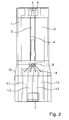
- Decisive with respect to the sensor element 2 here is that areas on the top and bottom of the sensor element 2 are not covered by the encapsulation 3 and are flowed around in this way by the flow S to be measured unhindered, as in FIG. 1 is indicated.
- the region not covered by the encapsulation 3 on the top and bottom of the sensor element 2 is in the example shown in each case rectangular, wherein the longitudinal axis of this region extends along the longitudinal axis of the flow sensor.
- the top and bottom of the sensor element 2 are designed to be non-binding and there is no encapsulation 3 is provided.
- the heating element 4 is arranged in the present embodiment;
- the end-placed temperature sensor 5 is covered by the molding compound of the encapsulation 3. The latter is not mandatory for the present invention, ie the Temperature sensor could also be uncovered by the encapsulation and thus also be free in the flow.
- the mass flow measurement with the flow sensor according to the invention can be optimized again by arranging an additional cylindrical body (not shown in the figures) in the flow S in front of the flow sensor. For positioning of such a body and for further optimization of the flow guidance, it may also be advantageous to arrange the sensor element 2 still a suitably designed flow housing in the form of an attachable flow head.
- the encapsulation 3 closes on both sides positively against the sensor element 2. Laterally adjacent to the sensor element 2, the areas of the encapsulation 3 are formed as leading edges for the flow S to be measured. In the illustrated embodiment, incidental edges formed on both adjacent sides of the sensor element 2 are provided with mirror symmetry to an axis of symmetry. In the region of the sensor element 2 results in a dumbbell-shaped cross-section of the flow sensor, as shown in the sectional view of FIG. 3 is shown.
- the so formed on the encapsulation 3 leading edges for the flow to be measured S each have a curved cross section, which is formed in the present example in approximately elliptical.
- the shape corresponds in profile in about a symmetrically-shaped wing. In this way it is ensured on the one hand that the flow S to be measured at the flow sensor does not act on any edge. In this way, disturbing dirt deposits in the region of the sensor element 2 and thus any erroneous measurements can be reliably avoided.
- such shaping of the leading edges ensures that the flow S to be measured is swept evenly over the sensor element 2, i. It is thereby avoided that the sensor element 2 possibly comes to rest in the lee of an obstacle.
- the encapsulation 3 has further important functions for the flow sensor according to the invention.
- the encapsulation 3 also serves as a mechanical and chemical protection for the sensor element 2, for the contacting regions 9 of the sensor element 2, for the electrical connections 8 and for the carrier part 1.
- the encapsulation 3 also has approximately in the middle of the flow sensor, a positioning portion 10 with a slightly conical shape. In this way, a guided and reproducible assembly of the flow sensor according to the invention in the respective application is possible, where a geometrically designed corresponding counterpart is available. Possible positioning errors during assembly can be avoided in this way.
- the laterally provided oblique surfaces of the positioning portion 10 can be used with suitable design of the counterpart furthermore as sealing surfaces.
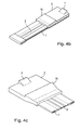
- a fastening element 7 is provided at one longitudinal end of the flow sensor, which serves for the releasable arrangement of the flow sensor on a suitable holding element - not shown in the figures.
- the fastening element 7 is realized as formed in the encapsulation 3 snap hook.
- the flow sensor can thus be e.g. put in a suitable socket and fixed.
- the encapsulation 3 is provided in the region of the finger-shaped connection regions 1.1 to 1.4 of the carrier part 1 only above these connection regions 1.1 to 1.4. That is, down the connection areas are 1.1 - 1.4 of the support member 1 free and can be used for electrical connection of the flow sensor according to the invention with a subsequent electronics.
- a corresponding contact can be made for example via a ribbon cable, which is soldered via a reflow soldering process to the contact areas 1.1 - 1.4.
- the sensor element 2 is first glued onto the carrier part 1. Subsequently, the bond connections are made via a suitable bonding process and in a final step, the transfer molding takes place.
- the carrier element in several parts instead of the single carrier substrate 2.1 of the sensor element 2 provided in the example described. So could e.g. on an elongated first carrier substrate, the heating element are arranged and on a second carrier substrate placed next to the temperature sensor. In the area between the two carrier substrates, the encapsulation or molding compound would then be arranged again, etc.
Landscapes
- Physics & Mathematics (AREA)
- Fluid Mechanics (AREA)
- General Physics & Mathematics (AREA)
- Measuring Volume Flow (AREA)
Applications Claiming Priority (1)
| Application Number | Priority Date | Filing Date | Title |
|---|---|---|---|
| DE102012009421A DE102012009421A1 (de) | 2012-05-11 | 2012-05-11 | Strömungssensor |
Publications (2)
| Publication Number | Publication Date |
|---|---|
| EP2662670A1 EP2662670A1 (de) | 2013-11-13 |
| EP2662670B1 true EP2662670B1 (de) | 2016-11-09 |
Family
ID=48092663
Family Applications (1)
| Application Number | Title | Priority Date | Filing Date |
|---|---|---|---|
| EP13001841.9A Active EP2662670B1 (de) | 2012-05-11 | 2013-04-09 | Strömungssensor |
Country Status (6)
Families Citing this family (6)
| Publication number | Priority date | Publication date | Assignee | Title |
|---|---|---|---|---|
| JP3274814B2 (ja) | 1996-12-27 | 2002-04-15 | サンデン株式会社 | スクロール流体機械 |
| CN107076619B (zh) * | 2014-10-24 | 2021-01-22 | 沃特洛电气制造公司 | 快速响应传感器外壳 |
| DE102015219509A1 (de) * | 2015-10-08 | 2017-04-13 | Robert Bosch Gmbh | Sensorvorrichtung zur Erfassung mindestens einer Strömungseigenschaft eines strömenden fluiden Mediums |
| DE102015118123A1 (de) * | 2015-10-23 | 2017-04-27 | Endress+Hauser Flowtec Ag | Thermisches Durchflussmessgerät und Anordnung mit einem Rohr und dem thermischen Durchflussmessgerät |
| DE102015225358B4 (de) | 2015-12-16 | 2020-04-02 | Continental Automotive Gmbh | Luftmassenmesser |
| JP7112001B2 (ja) * | 2020-10-15 | 2022-08-03 | ダイキン工業株式会社 | 熱式流速・流量センサ、及び空気調和機 |
Family Cites Families (18)
| Publication number | Priority date | Publication date | Assignee | Title |
|---|---|---|---|---|
| DE2751196C2 (de) * | 1977-11-16 | 1985-06-20 | Robert Bosch Gmbh, 7000 Stuttgart | Vorrichtung zur Luftmengenmessung |
| JPS62123318A (ja) * | 1985-08-13 | 1987-06-04 | Nippon Soken Inc | 直熱型流量センサ |
| DE3838466C2 (de) * | 1988-01-16 | 1995-11-16 | Bosch Gmbh Robert | Luftmassenmeßvorrichtung und Verfahren zur Herstellung einer Luftmassenmeßvorrichtung |
| US4986122A (en) * | 1989-11-08 | 1991-01-22 | Hydro Data Inc. | Fluid velocity measurement instrument |
| JP2784286B2 (ja) * | 1991-12-09 | 1998-08-06 | 三菱電機株式会社 | 半導体センサー装置の製造方法 |
| JP3331814B2 (ja) * | 1995-05-18 | 2002-10-07 | 三菱電機株式会社 | 感熱式流量検出装置 |
| CN1155653A (zh) * | 1995-05-19 | 1997-07-30 | 株式会社日立制作所 | 质量气流传感器及其所用的测量器 |
| JP3416526B2 (ja) * | 1998-05-21 | 2003-06-16 | 三菱電機株式会社 | 感熱式流量センサ |
| JP3545637B2 (ja) | 1999-03-24 | 2004-07-21 | 三菱電機株式会社 | 感熱式流量センサ |
| DE10036290A1 (de) * | 2000-07-26 | 2002-02-07 | Bosch Gmbh Robert | Vorrichtung zur Bestimmung zumindest eines Parameters eines strömenden Mediums |
| JP3671393B2 (ja) * | 2001-05-24 | 2005-07-13 | 三菱電機株式会社 | 感熱式流量センサ |
| DE102005016122A1 (de) | 2005-04-08 | 2006-10-12 | Robert Bosch Gmbh | Verfahren zur Herstellung eines Strömungsmessers |
| JP4830391B2 (ja) * | 2005-07-29 | 2011-12-07 | 株式会社デンソー | センサ装置の製造方法及びセンサ装置 |
| JP2008058131A (ja) * | 2006-08-31 | 2008-03-13 | Hitachi Ltd | 熱式ガス流量計 |
| JP4882732B2 (ja) | 2006-12-22 | 2012-02-22 | 株式会社デンソー | 半導体装置 |
| JP5183164B2 (ja) * | 2007-11-19 | 2013-04-17 | 日立オートモティブシステムズ株式会社 | 流量測定装置 |
| US7654157B2 (en) * | 2007-11-30 | 2010-02-02 | Honeywell International Inc. | Airflow sensor with pitot tube for pressure drop reduction |
| JP2011508193A (ja) * | 2007-12-21 | 2011-03-10 | ノアグレン ゲゼルシャフト ミット ベシュレンクテル ハフツング | 乱流インデューサを備えた熱式流量センサー |
-
2012
- 2012-05-11 DE DE102012009421A patent/DE102012009421A1/de not_active Withdrawn
-
2013
- 2013-04-09 EP EP13001841.9A patent/EP2662670B1/de active Active
- 2013-04-19 KR KR1020130043637A patent/KR101930937B1/ko not_active Expired - Fee Related
- 2013-05-09 JP JP2013099176A patent/JP6100081B2/ja not_active Expired - Fee Related
- 2013-05-09 US US13/890,619 patent/US9091579B2/en active Active
- 2013-05-10 CN CN201310170786.7A patent/CN103389134B/zh active Active
Non-Patent Citations (1)
| Title |
|---|
| None * |
Also Published As
| Publication number | Publication date |
|---|---|
| JP6100081B2 (ja) | 2017-03-22 |
| EP2662670A1 (de) | 2013-11-13 |
| JP2013238594A (ja) | 2013-11-28 |
| DE102012009421A1 (de) | 2013-11-14 |
| KR101930937B1 (ko) | 2018-12-20 |
| KR20130126471A (ko) | 2013-11-20 |
| US20130298666A1 (en) | 2013-11-14 |
| CN103389134A (zh) | 2013-11-13 |
| CN103389134B (zh) | 2017-12-29 |
| US9091579B2 (en) | 2015-07-28 |
Similar Documents
| Publication | Publication Date | Title |
|---|---|---|
| EP2662670B1 (de) | Strömungssensor | |
| DE102005025667B4 (de) | Verfahren zur Herstellung einer Sensoranordnung mit einem umgossenen Signalausgabeabschnitt | |
| DE112013001060B4 (de) | Thermische Luftmengenmesseinrichtung | |
| EP2326923B1 (de) | Sensoranordnung zur bestimmung eines parameters eines fluiden mediums | |
| DE19524634B4 (de) | Vorrichtung zur Messung der Masse eines strömenden Mediums | |
| DE102006035000B4 (de) | Sensorvorrichtung und Verfahren zu deren Fertigung | |
| DE60030333T2 (de) | Einrichtung zur messung einer physikalischen grösse, verfahren zu ihrer herstellung und fahrzeugsteuersystem mit der einrichtung zur messung einer physikalischen grösse | |
| DE19619910C2 (de) | Meßelement für einen Massenluftstromsensor und Massenluftstromsensor, der das Meßelement verwendet | |
| DE112014002928T5 (de) | Gassensorvorrichtung und Installationsstruktur für eine Gassensorvorrichtung | |
| DE102014002991B4 (de) | Sensor-Gehäuse für die direkte Montage | |
| DE112010001128T5 (de) | Durchflusserfassungsbauelement und dessen verkappung | |
| EP2759811A2 (de) | Strömungssensorelement und dessen Selbstreinigung | |
| DE102013101731A1 (de) | Drucksensorsystem | |
| EP1917502A1 (de) | HEIßFILMLUFTMASSENMESSER MIT STRÖMUNGSABLÖSUNGSELEMENT | |
| DE112013006408T5 (de) | Durchflusssensor und Fertigungsverfahren dafür | |
| DE112012006049T5 (de) | Strömungssensor mit Herstellungsverfahren | |
| DE102005006158B4 (de) | Thermischer Luftmengenmesser und Verfahren zu seiner Herstellung | |
| DE102011083174B4 (de) | Sensor zur Erfassung eines Drucks und einer Temperatur eines fluiden Mediums | |
| DE10065723A1 (de) | Anordnung zur Temperaturmessung und -regelung | |
| DE102004045854A1 (de) | Halbleitersensor mit einem Hohlraumgehäuse und Verfahren zur Herstellung desselben | |
| DE112016004983B4 (de) | Messvorrichtung für physikalische Größen | |
| WO2008034663A1 (de) | Sensoranordnung mit einem substrat und mit einem gehäuse und verfahren zur herstellung einer sensoranordnung | |
| DE102022211819B3 (de) | Elektronikbaugruppe und Verfahren zur Herstellung einer Elektronikbaugruppe | |
| DE102005055083B4 (de) | Thermoelektrischer Sensor und Verfahren zur Herstellung | |
| WO2013092102A1 (de) | Distanzstück für ein thermisches durchflussmessgerät |
Legal Events
| Date | Code | Title | Description |
|---|---|---|---|
| PUAI | Public reference made under article 153(3) epc to a published international application that has entered the european phase |
Free format text: ORIGINAL CODE: 0009012 |
|
| AK | Designated contracting states |
Kind code of ref document: A1 Designated state(s): AL AT BE BG CH CY CZ DE DK EE ES FI FR GB GR HR HU IE IS IT LI LT LU LV MC MK MT NL NO PL PT RO RS SE SI SK SM TR |
|
| AX | Request for extension of the european patent |
Extension state: BA ME |
|
| 17P | Request for examination filed |
Effective date: 20140513 |
|
| RBV | Designated contracting states (corrected) |
Designated state(s): AL AT BE BG CH CY CZ DE DK EE ES FI FR GB GR HR HU IE IS IT LI LT LU LV MC MK MT NL NO PL PT RO RS SE SI SK SM TR |
|
| GRAP | Despatch of communication of intention to grant a patent |
Free format text: ORIGINAL CODE: EPIDOSNIGR1 |
|
| RIC1 | Information provided on ipc code assigned before grant |
Ipc: G01F 1/684 20060101AFI20160607BHEP Ipc: G01F 1/74 20060101ALI20160607BHEP |
|
| INTG | Intention to grant announced |
Effective date: 20160713 |
|
| GRAS | Grant fee paid |
Free format text: ORIGINAL CODE: EPIDOSNIGR3 |
|
| GRAA | (expected) grant |
Free format text: ORIGINAL CODE: 0009210 |
|
| AK | Designated contracting states |
Kind code of ref document: B1 Designated state(s): AL AT BE BG CH CY CZ DE DK EE ES FI FR GB GR HR HU IE IS IT LI LT LU LV MC MK MT NL NO PL PT RO RS SE SI SK SM TR |
|
| REG | Reference to a national code |
Ref country code: GB Ref legal event code: FG4D Free format text: NOT ENGLISH |
|
| REG | Reference to a national code |
Ref country code: AT Ref legal event code: REF Ref document number: 844372 Country of ref document: AT Kind code of ref document: T Effective date: 20161115 Ref country code: CH Ref legal event code: EP Ref country code: CH Ref legal event code: NV Representative=s name: ICB INGENIEURS CONSEILS EN BREVETS SA, CH |
|
| REG | Reference to a national code |
Ref country code: IE Ref legal event code: FG4D Free format text: LANGUAGE OF EP DOCUMENT: GERMAN |
|
| REG | Reference to a national code |
Ref country code: DE Ref legal event code: R096 Ref document number: 502013005255 Country of ref document: DE |
|
| PG25 | Lapsed in a contracting state [announced via postgrant information from national office to epo] |
Ref country code: LV Free format text: LAPSE BECAUSE OF FAILURE TO SUBMIT A TRANSLATION OF THE DESCRIPTION OR TO PAY THE FEE WITHIN THE PRESCRIBED TIME-LIMIT Effective date: 20161109 |
|
| REG | Reference to a national code |
Ref country code: LT Ref legal event code: MG4D |
|
| REG | Reference to a national code |
Ref country code: NL Ref legal event code: MP Effective date: 20161109 |
|
| REG | Reference to a national code |
Ref country code: FR Ref legal event code: PLFP Year of fee payment: 5 |
|
| PG25 | Lapsed in a contracting state [announced via postgrant information from national office to epo] |
Ref country code: SE Free format text: LAPSE BECAUSE OF FAILURE TO SUBMIT A TRANSLATION OF THE DESCRIPTION OR TO PAY THE FEE WITHIN THE PRESCRIBED TIME-LIMIT Effective date: 20161109 Ref country code: GR Free format text: LAPSE BECAUSE OF FAILURE TO SUBMIT A TRANSLATION OF THE DESCRIPTION OR TO PAY THE FEE WITHIN THE PRESCRIBED TIME-LIMIT Effective date: 20170210 Ref country code: NL Free format text: LAPSE BECAUSE OF FAILURE TO SUBMIT A TRANSLATION OF THE DESCRIPTION OR TO PAY THE FEE WITHIN THE PRESCRIBED TIME-LIMIT Effective date: 20161109 Ref country code: LT Free format text: LAPSE BECAUSE OF FAILURE TO SUBMIT A TRANSLATION OF THE DESCRIPTION OR TO PAY THE FEE WITHIN THE PRESCRIBED TIME-LIMIT Effective date: 20161109 Ref country code: NO Free format text: LAPSE BECAUSE OF FAILURE TO SUBMIT A TRANSLATION OF THE DESCRIPTION OR TO PAY THE FEE WITHIN THE PRESCRIBED TIME-LIMIT Effective date: 20170209 |
|
| PG25 | Lapsed in a contracting state [announced via postgrant information from national office to epo] |
Ref country code: HR Free format text: LAPSE BECAUSE OF FAILURE TO SUBMIT A TRANSLATION OF THE DESCRIPTION OR TO PAY THE FEE WITHIN THE PRESCRIBED TIME-LIMIT Effective date: 20161109 Ref country code: ES Free format text: LAPSE BECAUSE OF FAILURE TO SUBMIT A TRANSLATION OF THE DESCRIPTION OR TO PAY THE FEE WITHIN THE PRESCRIBED TIME-LIMIT Effective date: 20161109 Ref country code: RS Free format text: LAPSE BECAUSE OF FAILURE TO SUBMIT A TRANSLATION OF THE DESCRIPTION OR TO PAY THE FEE WITHIN THE PRESCRIBED TIME-LIMIT Effective date: 20161109 Ref country code: PT Free format text: LAPSE BECAUSE OF FAILURE TO SUBMIT A TRANSLATION OF THE DESCRIPTION OR TO PAY THE FEE WITHIN THE PRESCRIBED TIME-LIMIT Effective date: 20170309 Ref country code: PL Free format text: LAPSE BECAUSE OF FAILURE TO SUBMIT A TRANSLATION OF THE DESCRIPTION OR TO PAY THE FEE WITHIN THE PRESCRIBED TIME-LIMIT Effective date: 20161109 Ref country code: IS Free format text: LAPSE BECAUSE OF FAILURE TO SUBMIT A TRANSLATION OF THE DESCRIPTION OR TO PAY THE FEE WITHIN THE PRESCRIBED TIME-LIMIT Effective date: 20170309 Ref country code: FI Free format text: LAPSE BECAUSE OF FAILURE TO SUBMIT A TRANSLATION OF THE DESCRIPTION OR TO PAY THE FEE WITHIN THE PRESCRIBED TIME-LIMIT Effective date: 20161109 |
|
| PG25 | Lapsed in a contracting state [announced via postgrant information from national office to epo] |
Ref country code: EE Free format text: LAPSE BECAUSE OF FAILURE TO SUBMIT A TRANSLATION OF THE DESCRIPTION OR TO PAY THE FEE WITHIN THE PRESCRIBED TIME-LIMIT Effective date: 20161109 Ref country code: CZ Free format text: LAPSE BECAUSE OF FAILURE TO SUBMIT A TRANSLATION OF THE DESCRIPTION OR TO PAY THE FEE WITHIN THE PRESCRIBED TIME-LIMIT Effective date: 20161109 Ref country code: SK Free format text: LAPSE BECAUSE OF FAILURE TO SUBMIT A TRANSLATION OF THE DESCRIPTION OR TO PAY THE FEE WITHIN THE PRESCRIBED TIME-LIMIT Effective date: 20161109 Ref country code: RO Free format text: LAPSE BECAUSE OF FAILURE TO SUBMIT A TRANSLATION OF THE DESCRIPTION OR TO PAY THE FEE WITHIN THE PRESCRIBED TIME-LIMIT Effective date: 20161109 Ref country code: DK Free format text: LAPSE BECAUSE OF FAILURE TO SUBMIT A TRANSLATION OF THE DESCRIPTION OR TO PAY THE FEE WITHIN THE PRESCRIBED TIME-LIMIT Effective date: 20161109 |
|
| REG | Reference to a national code |
Ref country code: DE Ref legal event code: R097 Ref document number: 502013005255 Country of ref document: DE |
|
| PG25 | Lapsed in a contracting state [announced via postgrant information from national office to epo] |
Ref country code: SM Free format text: LAPSE BECAUSE OF FAILURE TO SUBMIT A TRANSLATION OF THE DESCRIPTION OR TO PAY THE FEE WITHIN THE PRESCRIBED TIME-LIMIT Effective date: 20161109 Ref country code: BG Free format text: LAPSE BECAUSE OF FAILURE TO SUBMIT A TRANSLATION OF THE DESCRIPTION OR TO PAY THE FEE WITHIN THE PRESCRIBED TIME-LIMIT Effective date: 20170209 |
|
| PLBE | No opposition filed within time limit |
Free format text: ORIGINAL CODE: 0009261 |
|
| STAA | Information on the status of an ep patent application or granted ep patent |
Free format text: STATUS: NO OPPOSITION FILED WITHIN TIME LIMIT |
|
| 26N | No opposition filed |
Effective date: 20170810 |
|
| PG25 | Lapsed in a contracting state [announced via postgrant information from national office to epo] |
Ref country code: SI Free format text: LAPSE BECAUSE OF FAILURE TO SUBMIT A TRANSLATION OF THE DESCRIPTION OR TO PAY THE FEE WITHIN THE PRESCRIBED TIME-LIMIT Effective date: 20161109 |
|
| REG | Reference to a national code |
Ref country code: IE Ref legal event code: MM4A |
|
| PG25 | Lapsed in a contracting state [announced via postgrant information from national office to epo] |
Ref country code: MC Free format text: LAPSE BECAUSE OF FAILURE TO SUBMIT A TRANSLATION OF THE DESCRIPTION OR TO PAY THE FEE WITHIN THE PRESCRIBED TIME-LIMIT Effective date: 20161109 |
|
| PG25 | Lapsed in a contracting state [announced via postgrant information from national office to epo] |
Ref country code: LU Free format text: LAPSE BECAUSE OF NON-PAYMENT OF DUE FEES Effective date: 20170409 |
|
| REG | Reference to a national code |
Ref country code: BE Ref legal event code: MM Effective date: 20170430 |
|
| REG | Reference to a national code |
Ref country code: FR Ref legal event code: PLFP Year of fee payment: 6 |
|
| PG25 | Lapsed in a contracting state [announced via postgrant information from national office to epo] |
Ref country code: IE Free format text: LAPSE BECAUSE OF NON-PAYMENT OF DUE FEES Effective date: 20170409 |
|
| PG25 | Lapsed in a contracting state [announced via postgrant information from national office to epo] |
Ref country code: BE Free format text: LAPSE BECAUSE OF NON-PAYMENT OF DUE FEES Effective date: 20170430 |
|
| PG25 | Lapsed in a contracting state [announced via postgrant information from national office to epo] |
Ref country code: MT Free format text: LAPSE BECAUSE OF FAILURE TO SUBMIT A TRANSLATION OF THE DESCRIPTION OR TO PAY THE FEE WITHIN THE PRESCRIBED TIME-LIMIT Effective date: 20161109 |
|
| PG25 | Lapsed in a contracting state [announced via postgrant information from national office to epo] |
Ref country code: HU Free format text: LAPSE BECAUSE OF FAILURE TO SUBMIT A TRANSLATION OF THE DESCRIPTION OR TO PAY THE FEE WITHIN THE PRESCRIBED TIME-LIMIT; INVALID AB INITIO Effective date: 20130409 |
|
| PG25 | Lapsed in a contracting state [announced via postgrant information from national office to epo] |
Ref country code: CY Free format text: LAPSE BECAUSE OF NON-PAYMENT OF DUE FEES Effective date: 20161109 |
|
| PG25 | Lapsed in a contracting state [announced via postgrant information from national office to epo] |
Ref country code: MK Free format text: LAPSE BECAUSE OF FAILURE TO SUBMIT A TRANSLATION OF THE DESCRIPTION OR TO PAY THE FEE WITHIN THE PRESCRIBED TIME-LIMIT Effective date: 20161109 |
|
| PG25 | Lapsed in a contracting state [announced via postgrant information from national office to epo] |
Ref country code: TR Free format text: LAPSE BECAUSE OF FAILURE TO SUBMIT A TRANSLATION OF THE DESCRIPTION OR TO PAY THE FEE WITHIN THE PRESCRIBED TIME-LIMIT Effective date: 20161109 |
|
| PG25 | Lapsed in a contracting state [announced via postgrant information from national office to epo] |
Ref country code: AL Free format text: LAPSE BECAUSE OF FAILURE TO SUBMIT A TRANSLATION OF THE DESCRIPTION OR TO PAY THE FEE WITHIN THE PRESCRIBED TIME-LIMIT Effective date: 20161109 |
|
| PGFP | Annual fee paid to national office [announced via postgrant information from national office to epo] |
Ref country code: FR Payment date: 20210423 Year of fee payment: 9 |
|
| PGFP | Annual fee paid to national office [announced via postgrant information from national office to epo] |
Ref country code: GB Payment date: 20210422 Year of fee payment: 9 |
|
| GBPC | Gb: european patent ceased through non-payment of renewal fee |
Effective date: 20220409 |
|
| PG25 | Lapsed in a contracting state [announced via postgrant information from national office to epo] |
Ref country code: GB Free format text: LAPSE BECAUSE OF NON-PAYMENT OF DUE FEES Effective date: 20220409 Ref country code: FR Free format text: LAPSE BECAUSE OF NON-PAYMENT OF DUE FEES Effective date: 20220430 |
|
| PGFP | Annual fee paid to national office [announced via postgrant information from national office to epo] |
Ref country code: IT Payment date: 20230426 Year of fee payment: 11 |
|
| PGFP | Annual fee paid to national office [announced via postgrant information from national office to epo] |
Ref country code: AT Payment date: 20230420 Year of fee payment: 11 |
|
| REG | Reference to a national code |
Ref country code: AT Ref legal event code: MM01 Ref document number: 844372 Country of ref document: AT Kind code of ref document: T Effective date: 20240409 |
|
| PG25 | Lapsed in a contracting state [announced via postgrant information from national office to epo] |
Ref country code: AT Free format text: LAPSE BECAUSE OF NON-PAYMENT OF DUE FEES Effective date: 20240409 |
|
| PG25 | Lapsed in a contracting state [announced via postgrant information from national office to epo] |
Ref country code: AT Free format text: LAPSE BECAUSE OF NON-PAYMENT OF DUE FEES Effective date: 20240409 |
|
| PG25 | Lapsed in a contracting state [announced via postgrant information from national office to epo] |
Ref country code: IT Free format text: LAPSE BECAUSE OF NON-PAYMENT OF DUE FEES Effective date: 20240409 |
|
| PGFP | Annual fee paid to national office [announced via postgrant information from national office to epo] |
Ref country code: DE Payment date: 20250422 Year of fee payment: 13 |
|
| PGFP | Annual fee paid to national office [announced via postgrant information from national office to epo] |
Ref country code: CH Payment date: 20250501 Year of fee payment: 13 |