EP2662590A1 - Air spring - Google Patents
Air spring Download PDFInfo
- Publication number
- EP2662590A1 EP2662590A1 EP11855016.9A EP11855016A EP2662590A1 EP 2662590 A1 EP2662590 A1 EP 2662590A1 EP 11855016 A EP11855016 A EP 11855016A EP 2662590 A1 EP2662590 A1 EP 2662590A1
- Authority
- EP
- European Patent Office
- Prior art keywords
- movable body
- stopper
- air spring
- holding body
- face
- Prior art date
- Legal status (The legal status is an assumption and is not a legal conclusion. Google has not performed a legal analysis and makes no representation as to the accuracy of the status listed.)
- Granted
Links
Images



Classifications
-
- B—PERFORMING OPERATIONS; TRANSPORTING
- B61—RAILWAYS
- B61F—RAIL VEHICLE SUSPENSIONS, e.g. UNDERFRAMES, BOGIES OR ARRANGEMENTS OF WHEEL AXLES; RAIL VEHICLES FOR USE ON TRACKS OF DIFFERENT WIDTH; PREVENTING DERAILING OF RAIL VEHICLES; WHEEL GUARDS, OBSTRUCTION REMOVERS OR THE LIKE FOR RAIL VEHICLES
- B61F5/00—Constructional details of bogies; Connections between bogies and vehicle underframes; Arrangements or devices for adjusting or allowing self-adjustment of wheel axles or bogies when rounding curves
- B61F5/02—Arrangements permitting limited transverse relative movements between vehicle underframe or bolster and bogie; Connections between underframes and bogies
- B61F5/04—Bolster supports or mountings
- B61F5/10—Bolster supports or mountings incorporating fluid springs
-
- B—PERFORMING OPERATIONS; TRANSPORTING
- B60—VEHICLES IN GENERAL
- B60G—VEHICLE SUSPENSION ARRANGEMENTS
- B60G11/00—Resilient suspensions characterised by arrangement, location or kind of springs
- B60G11/26—Resilient suspensions characterised by arrangement, location or kind of springs having fluid springs only, e.g. hydropneumatic springs
- B60G11/27—Resilient suspensions characterised by arrangement, location or kind of springs having fluid springs only, e.g. hydropneumatic springs wherein the fluid is a gas
-
- B—PERFORMING OPERATIONS; TRANSPORTING
- B61—RAILWAYS
- B61F—RAIL VEHICLE SUSPENSIONS, e.g. UNDERFRAMES, BOGIES OR ARRANGEMENTS OF WHEEL AXLES; RAIL VEHICLES FOR USE ON TRACKS OF DIFFERENT WIDTH; PREVENTING DERAILING OF RAIL VEHICLES; WHEEL GUARDS, OBSTRUCTION REMOVERS OR THE LIKE FOR RAIL VEHICLES
- B61F5/00—Constructional details of bogies; Connections between bogies and vehicle underframes; Arrangements or devices for adjusting or allowing self-adjustment of wheel axles or bogies when rounding curves
- B61F5/02—Arrangements permitting limited transverse relative movements between vehicle underframe or bolster and bogie; Connections between underframes and bogies
-
- F—MECHANICAL ENGINEERING; LIGHTING; HEATING; WEAPONS; BLASTING
- F16—ENGINEERING ELEMENTS AND UNITS; GENERAL MEASURES FOR PRODUCING AND MAINTAINING EFFECTIVE FUNCTIONING OF MACHINES OR INSTALLATIONS; THERMAL INSULATION IN GENERAL
- F16F—SPRINGS; SHOCK-ABSORBERS; MEANS FOR DAMPING VIBRATION
- F16F9/00—Springs, vibration-dampers, shock-absorbers, or similarly-constructed movement-dampers using a fluid or the equivalent as damping medium
- F16F9/02—Springs, vibration-dampers, shock-absorbers, or similarly-constructed movement-dampers using a fluid or the equivalent as damping medium using gas only or vacuum
- F16F9/04—Springs, vibration-dampers, shock-absorbers, or similarly-constructed movement-dampers using a fluid or the equivalent as damping medium using gas only or vacuum in a chamber with a flexible wall
- F16F9/05—Springs, vibration-dampers, shock-absorbers, or similarly-constructed movement-dampers using a fluid or the equivalent as damping medium using gas only or vacuum in a chamber with a flexible wall the flexible wall being of the rolling diaphragm type
- F16F9/052—Springs, vibration-dampers, shock-absorbers, or similarly-constructed movement-dampers using a fluid or the equivalent as damping medium using gas only or vacuum in a chamber with a flexible wall the flexible wall being of the rolling diaphragm type characterised by the bumper
-
- B—PERFORMING OPERATIONS; TRANSPORTING
- B60—VEHICLES IN GENERAL
- B60G—VEHICLE SUSPENSION ARRANGEMENTS
- B60G2202/00—Indexing codes relating to the type of spring, damper or actuator
- B60G2202/10—Type of spring
- B60G2202/15—Fluid spring
- B60G2202/152—Pneumatic spring
-
- B—PERFORMING OPERATIONS; TRANSPORTING
- B60—VEHICLES IN GENERAL
- B60G—VEHICLE SUSPENSION ARRANGEMENTS
- B60G2206/00—Indexing codes related to the manufacturing of suspensions: constructional features, the materials used, procedures or tools
- B60G2206/01—Constructional features of suspension elements, e.g. arms, dampers, springs
- B60G2206/40—Constructional features of dampers and/or springs
- B60G2206/42—Springs
- B60G2206/424—Plunger or top retainer construction for bellows or rolling lobe type air springs
-
- F—MECHANICAL ENGINEERING; LIGHTING; HEATING; WEAPONS; BLASTING
- F16—ENGINEERING ELEMENTS AND UNITS; GENERAL MEASURES FOR PRODUCING AND MAINTAINING EFFECTIVE FUNCTIONING OF MACHINES OR INSTALLATIONS; THERMAL INSULATION IN GENERAL
- F16F—SPRINGS; SHOCK-ABSORBERS; MEANS FOR DAMPING VIBRATION
- F16F9/00—Springs, vibration-dampers, shock-absorbers, or similarly-constructed movement-dampers using a fluid or the equivalent as damping medium
- F16F9/02—Springs, vibration-dampers, shock-absorbers, or similarly-constructed movement-dampers using a fluid or the equivalent as damping medium using gas only or vacuum
- F16F9/04—Springs, vibration-dampers, shock-absorbers, or similarly-constructed movement-dampers using a fluid or the equivalent as damping medium using gas only or vacuum in a chamber with a flexible wall
- F16F9/05—Springs, vibration-dampers, shock-absorbers, or similarly-constructed movement-dampers using a fluid or the equivalent as damping medium using gas only or vacuum in a chamber with a flexible wall the flexible wall being of the rolling diaphragm type
Definitions
- the present invention relates to an air spring that, for example, is used for a railway vehicle and includes a stopper for limiting a displacement amount in a vertical direction.
- air springs that are interposed between a wheel side and a vehicle body side are mounted in a railway vehicle or the like to suppress vibrations (see Figure 7 ).
- Upper and lower stoppers 101 and 102 for limiting a displacement amount in the vertical direction are provided in the air spring.
- the upper and lower stoppers 101 and 102 are arranged so as to suppress the range of swaying that is produced by rolling of the vehicle body and prevent the vehicle body from contacting equipment in the surrounding area.
- the height of the air spring can be adjusted by supplying or discharging air to or from the air spring.
- the air spring is also used as an apparatus for adjusting the height of the vehicle body that has decreased to return the vehicle body height to the original level thereof.
- Patent Literature 1 discloses an air spring that, by making a space between upper and lower stoppers adjustable, is configured to be capable of preventing a widening of the space between the upper and lower stoppers while adjusting the height of the air spring (see Figure 8 ).
- an upper stopper member 103 and a lower stopper member 104 are provided on an upper face plate and a lower face plate, respectively.
- the upper stopper member 103 is configured to be rotatable.
- Flat faces 105 and 106 and protruding faces 107 and 108 are provided on the two stopper members 103 and 104.
- the space between the upper and lower stopper members 103 and 104 can be set to a predetermined range by rotating the upper stopper member 103 and selecting whether to cause the protruding faces 107 and 108 to face each other or to cause the flat faces 105 and 106 and the protruding faces 107 and 108 to face each other.
- the space between the stoppers is adjusted by rotating the upper stopper member that is provided on the upper face plate.
- the air spring disclosed in Patent Literature 1 has a structure such that an operator selects whether to cause the protruding faces of the upper and lower stopper members to contact against each other or to cause the flat faces and the protruding faces to contact against each other, and in a case where a displacement occurs in the horizontal direction of the air spring, there is a risk that the protruding faces will not contact against each other as intended or the flat faces and protruding faces will not contact against each other as intended. In such case, the stoppers no longer function normally and there is also a risk that the upper and lower protruding faces will only contact against each other in a narrow area at the edges thereof and will cause damage to the stopper members.
- An object of the present invention is to provide an air spring that can easily and reliably adjust a space between stoppers, and can prevent damage to the stoppers.
- an air spring according to the present invention is an air spring in which an upper member and a lower member are secured to upper and lower ends of a bellows, respectively, and stopper faces that contact against each other and limit a displacement amount of the upper member are formed on the upper member and the lower member, the lower member including: a movable body that can move vertically to adjust a height of the stopper face of the lower member, and a holding body that holds the movable body in a manner that enables vertical movement thereof, wherein: the movable body is configured to be capable of relative rotation around a central axis with respect to the holding body; and on at least one of the movable body and the holding body, a taper that is slidable with respect to the other of the movable body and the holding body is formed that inclines in a circumferential direction of the movable body relative to a horizontal surface.
- the movable body can be caused to move vertically by merely rotating the movable body relative to the holding body to cause the taper of the movable body and/or the holding body to slide with respect to the other of the movable body and the holding body. Further, since the movable body and the holding body are provided on the lower member, without dismounting the vehicle body from over the air spring, the movable body can be caused to move vertically to adjust the height of the stopper face of the lower member, and a space between the stoppers can be easily and reliably adjusted.
- each stopper face is not particularly limited, it is favorable to adopt a configuration in which the stopper face of at least one of the upper member and the lower member is formed in a flat shape.
- the stoppers can be caused to function normally, and easy and reliable adjustment of the stopper space can be ensured. That is, with regard to the stopper face that has a flat shape, since a situation does not arise in which a space between the stopper face and the other stopper changes at each area thereof, even if a displacement to some extent in the horizontal direction also occurs when the air spring changes position in the vertical direction, the two stopper faces can be caused to contact against each other with a vertical displacement amount that is in accordance with a set amount.
- the stopper faces are formed in a flat shape, a situation does not arise where the upper and lower stopper faces contact each other only at narrow areas at the ends of the convex portions thereof, which is a situation that arises when the two stopper faces are formed in a convexo-concave shape.
- the two stopper faces can be caused to securely contact against each other over a wide area and thus prevent the occurrence of damage to the stopper faces.
- the movable body can be positioned by causing one of the movable body and the holding body to ride up onto a horizontal surface of the other of the movable body and the holding body and a force in a vertical direction that acts between the movable body and the holding body can be efficiently received by the horizontal surface, and a force that causes the movable body to rotate with respect to the holding body can be prevented from arising by the action of the tapers.
- a configuration may also be adopted in which only a single taper is formed without providing a horizontal surface and, for example, a stopper face is positioned at a desired height by restricting rotation of the movable body with respect to the holding body to thereby prevent vertical movement of the movable body.
- a configuration can also be adopted in which a handle is provided that causes one of the movable body and the holding body to rotate, and a fixing portion is provided that fixes the handle to the other of the movable body and the holding body.
- the movable body can be easily caused to rotate relative to the holding body, and furthermore, since the handle can be fixed to the other of the movable body and the holding body by the fixing portion, rotation of the movable body with respect to the holding body can be prevented and the movable body can be reliably positioned.
- the present invention provides a stopper for an air spring that is provided on a lower member of an air spring and that contacts against an upper member of the air spring to limit a displacement amount of the upper member
- the stopper for an air spring including: a movable body that can move vertically to adjust a height of a stopper face of the lower member, and a holding body that holds the movable body in a manner that enables vertical movement thereof, in which: the movable body is configured to be capable of relative rotation around a central axis with respect to the holding body; and on at least one of the movable body and the holding body, a taper that is slidable with respect to the other of the movable body and the holding body is formed that inclines in a circumferential direction of the movable body relative to a horizontal surface.
- the configuration of principal portions is the same as in the above described air spring, and accordingly similar effects as those of the above described air spring are obtained by the stopper for an air spring.
- a movable body and a holding body are provided on a lower member of an air spring, and a taper is formed on at least one of the movable body and the holding body, the movable body can be caused to rotate with respect to the holding body and thereby caused to move vertically, and thus the height of a stopper face can be easily adjusted without dismounting the vehicle body from over the air spring.
- the range of swaying that is produced by rolling of the vehicle body can be suppressed by adjusting the space between the upper and lower stopper faces while adjusting the vehicle body height by supplying or discharging air to or from the air spring.
- a stopper face of at least one of the upper member and the lower member in a flat shape, even if a horizontal displacement of the air spring occurs, the space between the upper and lower stopper faces can be reliably adjusted and damage of the stoppers can be prevented.
- an air spring 1 for example, is interposed between a vehicle body side and a wheel side of a railway vehicle to suppress vibrations of the railway vehicle, and furthermore, when the wheels are worn, the air spring 1 is used to adjust the vehicle body height to the regular height thereof by supplying or discharging air to or from the air spring 1.
- the air spring 1 has a structure in which an upper member 3 that is attachable to the vehicle body side is secured to an upper end of a bellows 2 that is made from a tubular rubber membrane, a lower member 4 that is attachable to the wheel side is secured to a lower end of the bellows 2, and stopper faces 5 and 6 that contact against each other to limit a displacement amount in the vertical direction of the upper member 3 are formed on the upper member 3 and the lower member 4.
- the air spring 1 also includes, on the lower member 4 thereof, a movable body 7 that can move vertically to adjust the height of a stopper face 6 of the lower member 4, and a holding body 8 that holds the movable body 7 in a manner that enables vertical movement thereof.
- the upper member 3 is provided with a circular upper face plate 9 that is made of steel, for example, and a rubber seat 10 that protrudes in a ring shape from a lower face thereof, and has a structure in which, at a central part of the upper face plate 9, a connecting portion 11 is provided that protrudes to the upper side and is connected to a pressurized air supply portion (unshown).
- a connecting portion 11 is provided in the rubber seat 10 that protrudes to the upper side and is connected to a pressurized air supply portion (unshown).
- a ringshaped metal piece is covered with rubber.
- an upper stopper 12 is provided that is made of rubber.
- the lower face of the upper stopper 12 is taken as a stopper face 5.
- the stopper face 5 is formed in a convexo-concave shape in which a plurality of grooves that are parallel to a radial direction are formed. The grooves serve as a path for air that flows to the bellows 2 from the connecting portion 11 when supplying air into the air spring 1 from which air had escaped and in which the two stopper faces 5 and 6 are contacting against each other.
- a cylindrical portion 13 that protrudes downwards is formed at a peripheral edge portion of the upper face plate 9.
- the cylindrical portion 13 is folded back so as to press the lower end thereof upward and inward, and regulates expansion of the bellows 2 to which air was supplied.
- the inner surface of the cylindrical portion 13 is covered with a rubber 14, and is configured so as to reduce abrasion of the bellows 2 when the upper member 3 changes position in the horizontal direction.
- the lower member 4 has a structure in which a lower stopper 16 that contacts against the upper stopper 12 to limit a displacement amount of the upper member 3 is attached to a spring seat 17, and the spring seat 17 is secured to an upper face side of a laminated rubber 15.
- the lower stopper 16 includes the holding body 8 that is secured to the spring seat 17, the movable body 7 that the holding body 8 holds, and a handle 19 that rotates the movable body 7 around a central axis 18.
- the spring seat 17, for example, is made of steel and formed in a disk shape, a circular anti-slip device 20 formed on a lower face thereof is engaged in a center hole 21 of the laminated rubber 15, and the spring seat 17 is fixed by bolts to the laminated rubber 15 by inserting bolts 23 into bolt holes 22.
- a support shaft 25 that protrudes from the center to the upper side and supports a boss portion 24 of the handle 19 is formed in the spring seat 17.
- a notch 27 for positioning an arm 26 of the handle 19 is formed, for example, in a fan shape in which a central angle is approximately 60° in the spring seat 17.
- the handle 19 is formed by providing the boss portion 24 that engages with the movable body 7 at a proximal end portion of the arm 26, and a distal end portion thereof is operated to rotationally move the movable body 7 around the central axis 18.
- a pin hole 28 as a fixing portion provided at the distal end portion is fixed to the holding body 8 to prevent rotation of the movable body 7.
- the movable body 7 is, for example, a disk shape and is made from a metal such as aluminum or a synthetic resin.
- a fitting hole 29 in which the boss portion 20 of the handle 19 is fitted is formed in a central part of the movable body 7.
- the upper face of the movable body 7 is taken as the stopper face 6 that has a flat shape.
- horizontal surfaces 31 that protrude to the lower side from a lower face 30 of the movable body 7 are formed at a plurality of places, and a plurality of tapers 32 that incline in the circumferential direction of the movable body 7 relative to the horizontal surfaces, and intermediate horizontal surfaces 33 are alternatively formed so as to connect the lower face 30 of the movable body 7 and each horizontal surface 31.
- the holding body 8 is, for example, formed in a disk shape and is made from a metal such as aluminum or a synthetic resin.
- a through hole 34 through which the support shaft 25 of the spring seat 17 and the boss portion 24 of the handle 19 are inserted is formed in a central part of the holding body 8.
- a cylindrical portion 35 is formed on an upper face side of the holding body 8. The cylindrical portion 35 holds the movable body 7 in a condition that allows the movable body 7 to move vertically and to also rotate around the central axis 18.
- the boss portion 24 of the handle 19 that is fitted onto the exterior of the support shaft 25 is interposed between the holding body 8 and the spring seat 17, and the holding body 8 is fixed by bolts to the spring seat 17 by means of bolts 37 that are inserted through bolt holes 36 and screwed into screw holes 46.
- a rubber seat 38 is provided at a position that is further on an outer circumferential side than the cylindrical portion 35 of the holding body 8, and the holding body 8 also functions as a bead seat that secures and seals the lower end of the bellows 2.
- horizontal surfaces 40 that protrude from an upper face 39 of the holding body 8 to the upper side are formed at a plurality of places, and a plurality of tapers 41 that incline in the circumferential direction of the movable body 7 relative to the horizontal surfaces, and intermediate horizontal surfaces 42 are alternatively formed so as to connect the upper face 39 of the holding body 8 and each horizontal surface 40.
- the movable body 7 is inserted into the cylindrical portion 35 of the holding body 8, and the lower face 30, the horizontal surfaces 31, the tapers 32, and the intermediate horizontal surfaces 33 of the movable body 7, and the horizontal surfaces 40, the upper face 39, the tapers 41, and the intermediate horizontal surfaces 42 of the holding body 8 mesh together.
- the tapers 32 of the movable body 7 and the tapers 41 of the holding body 8 are capable of sliding with respect to each other, and the configuration is such that the movable body 7 is moved in the vertical direction by operating the handle 19 to rotate the movable body 7 around the central axis 18.
- the movable body 7 is positioned in the height direction in a plurality of states in which the lower face 30, the horizontal surfaces 31, and the intermediate horizontal surfaces 33 of the movable body 7 have ridden up onto the horizontal surfaces 40, the upper face 39, and the intermediate horizontal surfaces 42 of the holding body 8.
- a plurality of pin insertion holes 44 into which a pin 43 that is inserted through the pin hole 28 of the handle 19 is inserted are formed in the lower face of the holding body 8, and a configuration is adopted such that the handle 19 is fixed with respect to the holding body 8 in a state in which the movable body 7 has been positioned in the height direction.
- the pin 43 that has been inserted through the pin hole 28 is prevented from dropping out of the pin hole 28 by a split pin 45.
- the movable body 7 moves between a state in which the lower face 30 thereof is mounted on the upper face 39 of the holding body 8 (a-1, b-1) and a state in which the lower face 30 thereof is mounted on the horizontal surfaces 40 of the holding body 8 (a-4, b-4), and between those states the movable body 7 is temporarily positioned in states in which the lower face 30 is mounted on the intermediate horizontal surfaces 42 of the holding body 8 (a-2, b-2) and (a-3, b-3).
- the position of the pin hole 28 of the handle 19 corresponds to a position of one pin insertion hole 44 in the lower face of the holding body 8.
- the height adjustment of the stopper face 6 on the lower side is completed by inserting the pin 43 into the pin hole 28 and the pin insertion hole 44 and preventing the pin 43 from falling out using the split pin 45, to thereby restrict vertical movement of the movable body 7.
- the stopper space can be easily adjusted without dismounting the vehicle body from over the air spring 1.
- the stopper face 6 on the lower side is formed in a flat shape, even if the air spring 1 changes position in the horizontal direction and a deviation arises with respect to a center position between the upper member 3 and the lower member 4, the space between the two stopper faces 5 and 6 does not change and the stopper space can be maintained at the set space. Further, since the stopper face 6 on the lower side is a flat shape, the stopper faces 5 and 6 do not come in contact at a narrow area of protruding portions, and thus damage to the stopper faces 5 and 6 can be prevented.
- the present invention is not limited to the above described embodiment, and can be suitably changed within the scope of the present invention.
- the air spring 1 is not limited to an air spring for a railway vehicle and may be an air spring that is used for another purpose.
- the holding body 8 and the spring seat 17 may also be formed in an integrated manner, and need not be formed as separate elements.
- the movable body 7 is capable of relative rotation around the central axis 18 with respect to the holding body 8, and a configuration may also be adopted in which the holding body 8 is rotated instead of the movable body 7.
- stopper faces 5 and 6 It is sufficient to form at least one of the stopper faces 5 and 6 in a flat shape, and it is sufficient to form only the stopper face 5 on the upper side in a flat shape instead of forming the stopper face 6 on the lower side in a flat shape, and a configuration may also be adopted in which both of the stopper faces 5 and 6 are formed in a flat shape.
- An air spring according to the present invention can be favorably adopted, for example, for use as an air spring that is interposed between a wheel side and a vehicle body side of a railway vehicle to limit a displacement amount in a vertical direction of a stopper thereof while suppressing vibrations of the railway vehicle.
Landscapes
- Engineering & Computer Science (AREA)
- Mechanical Engineering (AREA)
- General Engineering & Computer Science (AREA)
- Fluid-Damping Devices (AREA)
- Vibration Prevention Devices (AREA)
Abstract
Description
- The present invention relates to an air spring that, for example, is used for a railway vehicle and includes a stopper for limiting a displacement amount in a vertical direction.
- In general, air springs that are interposed between a wheel side and a vehicle body side are mounted in a railway vehicle or the like to suppress vibrations (see
Figure 7 ). Upper andlower stoppers lower stoppers - However, when adjusting the vehicle body height, if the height of the air spring is merely raised, a space between the upper and
lower stoppers - With regard to this problem, for example,
Patent Literature 1 discloses an air spring that, by making a space between upper and lower stoppers adjustable, is configured to be capable of preventing a widening of the space between the upper and lower stoppers while adjusting the height of the air spring (seeFigure 8 ). - In the air spring disclosed in
Patent Literature 1, anupper stopper member 103 and alower stopper member 104 are provided on an upper face plate and a lower face plate, respectively. Theupper stopper member 103 is configured to be rotatable.Flat faces 105 and 106 and protrudingfaces stopper members lower stopper members upper stopper member 103 and selecting whether to cause theprotruding faces flat faces 105 and 106 and theprotruding faces -
- Patent Literature 1: Japanese Patent Laid-Open No.
9-89029 Figure 1 ) - In the air spring disclosed in
Patent Literature 1, the space between the stoppers is adjusted by rotating the upper stopper member that is provided on the upper face plate. However, when adjusting the space between the stoppers, it is necessary to extract the bogie from the vehicle body and dismount the vehicle body from over the air spring. - In addition, the air spring disclosed in
Patent Literature 1 has a structure such that an operator selects whether to cause the protruding faces of the upper and lower stopper members to contact against each other or to cause the flat faces and the protruding faces to contact against each other, and in a case where a displacement occurs in the horizontal direction of the air spring, there is a risk that the protruding faces will not contact against each other as intended or the flat faces and protruding faces will not contact against each other as intended. In such case, the stoppers no longer function normally and there is also a risk that the upper and lower protruding faces will only contact against each other in a narrow area at the edges thereof and will cause damage to the stopper members. - An object of the present invention is to provide an air spring that can easily and reliably adjust a space between stoppers, and can prevent damage to the stoppers.
- To achieve the aforementioned object, an air spring according to the present invention is an air spring in which an upper member and a lower member are secured to upper and lower ends of a bellows, respectively, and stopper faces that contact against each other and limit a displacement amount of the upper member are formed on the upper member and the lower member, the lower member including: a movable body that can move vertically to adjust a height of the stopper face of the lower member, and a holding body that holds the movable body in a manner that enables vertical movement thereof, wherein: the movable body is configured to be capable of relative rotation around a central axis with respect to the holding body; and on at least one of the movable body and the holding body, a taper that is slidable with respect to the other of the movable body and the holding body is formed that inclines in a circumferential direction of the movable body relative to a horizontal surface.
- According to the above described configuration, since a taper that inclines in a circumferential direction relative to a horizontal surface is formed in the movable body and/or the holding body, the movable body can be caused to move vertically by merely rotating the movable body relative to the holding body to cause the taper of the movable body and/or the holding body to slide with respect to the other of the movable body and the holding body. Further, since the movable body and the holding body are provided on the lower member, without dismounting the vehicle body from over the air spring, the movable body can be caused to move vertically to adjust the height of the stopper face of the lower member, and a space between the stoppers can be easily and reliably adjusted.
- Although a shape of each stopper face is not particularly limited, it is favorable to adopt a configuration in which the stopper face of at least one of the upper member and the lower member is formed in a flat shape.
- According to this configuration, since the two stopper faces are not formed in a convexo-concave shape and at least one of the stopper faces is formed in a flat shape, even if a displacement occurs to some extent in the horizontal direction in the air spring, the stoppers can be caused to function normally, and easy and reliable adjustment of the stopper space can be ensured. That is, with regard to the stopper face that has a flat shape, since a situation does not arise in which a space between the stopper face and the other stopper changes at each area thereof, even if a displacement to some extent in the horizontal direction also occurs when the air spring changes position in the vertical direction, the two stopper faces can be caused to contact against each other with a vertical displacement amount that is in accordance with a set amount.
- In addition, because at least one of the stopper faces is formed in a flat shape, a situation does not arise where the upper and lower stopper faces contact each other only at narrow areas at the ends of the convex portions thereof, which is a situation that arises when the two stopper faces are formed in a convexo-concave shape. Hence, the two stopper faces can be caused to securely contact against each other over a wide area and thus prevent the occurrence of damage to the stopper faces.
- It is also possible to adopt a configuration in which a plurality of the tapers are formed, and a horizontal surface that positions the movable body in a height direction is provided between the respective tapers.
- According to this configuration, the movable body can be positioned by causing one of the movable body and the holding body to ride up onto a horizontal surface of the other of the movable body and the holding body and a force in a vertical direction that acts between the movable body and the holding body can be efficiently received by the horizontal surface, and a force that causes the movable body to rotate with respect to the holding body can be prevented from arising by the action of the tapers. Note that a configuration may also be adopted in which only a single taper is formed without providing a horizontal surface and, for example, a stopper face is positioned at a desired height by restricting rotation of the movable body with respect to the holding body to thereby prevent vertical movement of the movable body.
- Further, a configuration can also be adopted in which a handle is provided that causes one of the movable body and the holding body to rotate, and a fixing portion is provided that fixes the handle to the other of the movable body and the holding body.
- According to this configuration, since a handle is provided that causes one of the movable body and the holding body to rotate, the movable body can be easily caused to rotate relative to the holding body, and furthermore, since the handle can be fixed to the other of the movable body and the holding body by the fixing portion, rotation of the movable body with respect to the holding body can be prevented and the movable body can be reliably positioned.
- In addition, the present invention provides a stopper for an air spring that is provided on a lower member of an air spring and that contacts against an upper member of the air spring to limit a displacement amount of the upper member, the stopper for an air spring including: a movable body that can move vertically to adjust a height of a stopper face of the lower member, and a holding body that holds the movable body in a manner that enables vertical movement thereof, in which: the movable body is configured to be capable of relative rotation around a central axis with respect to the holding body; and on at least one of the movable body and the holding body, a taper that is slidable with respect to the other of the movable body and the holding body is formed that inclines in a circumferential direction of the movable body relative to a horizontal surface.
- In the stopper for an air spring that is configured in this manner, the configuration of principal portions is the same as in the above described air spring, and accordingly similar effects as those of the above described air spring are obtained by the stopper for an air spring.
- As described above, according to the present invention, since a movable body and a holding body are provided on a lower member of an air spring, and a taper is formed on at least one of the movable body and the holding body, the movable body can be caused to rotate with respect to the holding body and thereby caused to move vertically, and thus the height of a stopper face can be easily adjusted without dismounting the vehicle body from over the air spring.
- As a result, for example, when the wheels of a railway vehicle are worn, the range of swaying that is produced by rolling of the vehicle body can be suppressed by adjusting the space between the upper and lower stopper faces while adjusting the vehicle body height by supplying or discharging air to or from the air spring. Further, by forming a stopper face of at least one of the upper member and the lower member in a flat shape, even if a horizontal displacement of the air spring occurs, the space between the upper and lower stopper faces can be reliably adjusted and damage of the stoppers can be prevented.
-
- [
Figure 1] Figure 1 is a sectional view of an air spring according to the present invention. - [
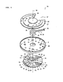
Figure 2] Figure 2 is a perspective view of a lower stopper as seen from an upper side. - [
Figure 3] Figure 3 is a perspective view of the lower stopper as seen from a lower side. - [
Figure 4] Figure 4 is an exploded perspective view of the lower stopper as seen from the upper side. - [
Figure 5] Figure 5 is an exploded perspective view of the lower stopper as seen from the lower side. - [
Figure 6] Figure 6 includes views that illustrate operations of the lower stopper, in which (a-1) to (a-4) are views as seen from the upper side and (b-1) to (b-4) are views as seen from the lower side. - [
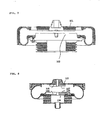
Figure 7] Figure 7 is a sectional view of a conventional air spring. - [
Figure 8] Figure 8 is a sectional view of an air spring equipped with a conventional stopper whose height is adjustable. - A form for implementing an air spring according to the present invention is described hereunder using the attached drawings.
- As shown in
Figure 1 , anair spring 1, for example, is interposed between a vehicle body side and a wheel side of a railway vehicle to suppress vibrations of the railway vehicle, and furthermore, when the wheels are worn, theair spring 1 is used to adjust the vehicle body height to the regular height thereof by supplying or discharging air to or from theair spring 1. Theair spring 1 has a structure in which anupper member 3 that is attachable to the vehicle body side is secured to an upper end of abellows 2 that is made from a tubular rubber membrane, alower member 4 that is attachable to the wheel side is secured to a lower end of thebellows 2, and stopperfaces upper member 3 are formed on theupper member 3 and thelower member 4. Theair spring 1 also includes, on thelower member 4 thereof, amovable body 7 that can move vertically to adjust the height of astopper face 6 of thelower member 4, and aholding body 8 that holds themovable body 7 in a manner that enables vertical movement thereof. - The
upper member 3 is provided with a circularupper face plate 9 that is made of steel, for example, and arubber seat 10 that protrudes in a ring shape from a lower face thereof, and has a structure in which, at a central part of theupper face plate 9, a connectingportion 11 is provided that protrudes to the upper side and is connected to a pressurized air supply portion (unshown). In therubber seat 10, for example, a ringshaped metal piece is covered with rubber. By fitting therubber seat 10 inside the upper end of thebellows 2, theupper member 3 is secured to the upper end of thebellows 2 and a space between therubber seat 10 and thebellows 2 is sealed, and air can be supplied to or discharged from thebellows 2 through the connectingportion 11. - On the lower face of the
upper face plate 9, at an area further on the inside than therubber seat 10 that is at the circumference of the connectingportion 11, anupper stopper 12 is provided that is made of rubber. The lower face of theupper stopper 12 is taken as astopper face 5. Thestopper face 5 is formed in a convexo-concave shape in which a plurality of grooves that are parallel to a radial direction are formed. The grooves serve as a path for air that flows to thebellows 2 from the connectingportion 11 when supplying air into theair spring 1 from which air had escaped and in which the two stopper faces 5 and 6 are contacting against each other. - A
cylindrical portion 13 that protrudes downwards is formed at a peripheral edge portion of theupper face plate 9. Thecylindrical portion 13 is folded back so as to press the lower end thereof upward and inward, and regulates expansion of thebellows 2 to which air was supplied. The inner surface of thecylindrical portion 13 is covered with arubber 14, and is configured so as to reduce abrasion of thebellows 2 when theupper member 3 changes position in the horizontal direction. - The
lower member 4 has a structure in which alower stopper 16 that contacts against theupper stopper 12 to limit a displacement amount of theupper member 3 is attached to aspring seat 17, and thespring seat 17 is secured to an upper face side of alaminated rubber 15. - As shown in
Figure 1 to Figure 5 , thelower stopper 16 includes the holdingbody 8 that is secured to thespring seat 17, themovable body 7 that the holdingbody 8 holds, and ahandle 19 that rotates themovable body 7 around acentral axis 18. - The
spring seat 17, for example, is made of steel and formed in a disk shape, a circularanti-slip device 20 formed on a lower face thereof is engaged in acenter hole 21 of thelaminated rubber 15, and thespring seat 17 is fixed by bolts to thelaminated rubber 15 by insertingbolts 23 into bolt holes 22. Asupport shaft 25 that protrudes from the center to the upper side and supports aboss portion 24 of thehandle 19 is formed in thespring seat 17. Further, anotch 27 for positioning anarm 26 of thehandle 19 is formed, for example, in a fan shape in which a central angle is approximately 60° in thespring seat 17. - The
handle 19 is formed by providing theboss portion 24 that engages with themovable body 7 at a proximal end portion of thearm 26, and a distal end portion thereof is operated to rotationally move themovable body 7 around thecentral axis 18. In addition, apin hole 28 as a fixing portion provided at the distal end portion is fixed to the holdingbody 8 to prevent rotation of themovable body 7. - The
movable body 7 is, for example, a disk shape and is made from a metal such as aluminum or a synthetic resin. Afitting hole 29 in which theboss portion 20 of thehandle 19 is fitted is formed in a central part of themovable body 7. The upper face of themovable body 7 is taken as thestopper face 6 that has a flat shape. On the lower face side of themovable body 7,horizontal surfaces 31 that protrude to the lower side from alower face 30 of themovable body 7 are formed at a plurality of places, and a plurality oftapers 32 that incline in the circumferential direction of themovable body 7 relative to the horizontal surfaces, and intermediatehorizontal surfaces 33 are alternatively formed so as to connect thelower face 30 of themovable body 7 and eachhorizontal surface 31. - The holding
body 8 is, for example, formed in a disk shape and is made from a metal such as aluminum or a synthetic resin. A throughhole 34 through which thesupport shaft 25 of thespring seat 17 and theboss portion 24 of thehandle 19 are inserted is formed in a central part of the holdingbody 8. Acylindrical portion 35 is formed on an upper face side of the holdingbody 8. Thecylindrical portion 35 holds themovable body 7 in a condition that allows themovable body 7 to move vertically and to also rotate around thecentral axis 18. - The
boss portion 24 of thehandle 19 that is fitted onto the exterior of thesupport shaft 25 is interposed between the holdingbody 8 and thespring seat 17, and the holdingbody 8 is fixed by bolts to thespring seat 17 by means ofbolts 37 that are inserted through bolt holes 36 and screwed into screw holes 46. Arubber seat 38 is provided at a position that is further on an outer circumferential side than thecylindrical portion 35 of the holdingbody 8, and the holdingbody 8 also functions as a bead seat that secures and seals the lower end of thebellows 2. - At positions on the upper face side of the holding
body 8 that are on the inner side of thecylindrical portion 35,horizontal surfaces 40 that protrude from anupper face 39 of the holdingbody 8 to the upper side are formed at a plurality of places, and a plurality oftapers 41 that incline in the circumferential direction of themovable body 7 relative to the horizontal surfaces, and intermediatehorizontal surfaces 42 are alternatively formed so as to connect theupper face 39 of the holdingbody 8 and eachhorizontal surface 40. - The
movable body 7 is inserted into thecylindrical portion 35 of the holdingbody 8, and thelower face 30, thehorizontal surfaces 31, thetapers 32, and the intermediatehorizontal surfaces 33 of themovable body 7, and thehorizontal surfaces 40, theupper face 39, thetapers 41, and the intermediatehorizontal surfaces 42 of the holdingbody 8 mesh together. Thetapers 32 of themovable body 7 and thetapers 41 of the holdingbody 8 are capable of sliding with respect to each other, and the configuration is such that themovable body 7 is moved in the vertical direction by operating thehandle 19 to rotate themovable body 7 around thecentral axis 18. - The
movable body 7 is positioned in the height direction in a plurality of states in which thelower face 30, thehorizontal surfaces 31, and the intermediatehorizontal surfaces 33 of themovable body 7 have ridden up onto thehorizontal surfaces 40, theupper face 39, and the intermediatehorizontal surfaces 42 of the holdingbody 8. - A plurality of pin insertion holes 44 into which a
pin 43 that is inserted through thepin hole 28 of thehandle 19 is inserted are formed in the lower face of the holdingbody 8, and a configuration is adopted such that thehandle 19 is fixed with respect to the holdingbody 8 in a state in which themovable body 7 has been positioned in the height direction. Thepin 43 that has been inserted through thepin hole 28 is prevented from dropping out of thepin hole 28 by asplit pin 45. - Next, operations of the lower stopper are described. As shown in
Figure 6 , thehandle 19 that is exposed from thenotch 27 is operated from the lower side of thespring seat 17 to rotate theboss portion 24 of thehandle 19 around thesupport shaft 25 of thespring seat 17. As a result, themovable body 7 that is engaged with theboss portion 24 at thefitting hole 29 rotates around thecentral axis 18, thetapers 32 of themovable body 7 and thetapers 41 of the holdingbody 8 slide with respect to each other, themovable body 7 moves in the vertical direction while rotating, and the height of thestopper face 6 on the lower side changes. - The
movable body 7 moves between a state in which thelower face 30 thereof is mounted on theupper face 39 of the holding body 8 (a-1, b-1) and a state in which thelower face 30 thereof is mounted on thehorizontal surfaces 40 of the holding body 8 (a-4, b-4), and between those states themovable body 7 is temporarily positioned in states in which thelower face 30 is mounted on the intermediatehorizontal surfaces 42 of the holding body 8 (a-2, b-2) and (a-3, b-3). - In a state in which the
movable body 7 has been positioned in the height direction and thestopper face 6 on the lower side has been adjusted to a desired height, the position of thepin hole 28 of thehandle 19 corresponds to a position of onepin insertion hole 44 in the lower face of the holdingbody 8. The height adjustment of thestopper face 6 on the lower side is completed by inserting thepin 43 into thepin hole 28 and thepin insertion hole 44 and preventing thepin 43 from falling out using thesplit pin 45, to thereby restrict vertical movement of themovable body 7. - According to the above described configuration, since the height of the
stopper face 6 can be adjusted by operating thehandle 19 from the lower side of thespring seat 17, the stopper space can be easily adjusted without dismounting the vehicle body from over theair spring 1. - Further, since the
stopper face 6 on the lower side is formed in a flat shape, even if theair spring 1 changes position in the horizontal direction and a deviation arises with respect to a center position between theupper member 3 and thelower member 4, the space between the two stopper faces 5 and 6 does not change and the stopper space can be maintained at the set space. Further, since thestopper face 6 on the lower side is a flat shape, the stopper faces 5 and 6 do not come in contact at a narrow area of protruding portions, and thus damage to the stopper faces 5 and 6 can be prevented. - Note that the present invention is not limited to the above described embodiment, and can be suitably changed within the scope of the present invention. For example, the
air spring 1 is not limited to an air spring for a railway vehicle and may be an air spring that is used for another purpose. Further, the holdingbody 8 and thespring seat 17 may also be formed in an integrated manner, and need not be formed as separate elements. - It is sufficient that the
movable body 7 is capable of relative rotation around thecentral axis 18 with respect to the holdingbody 8, and a configuration may also be adopted in which the holdingbody 8 is rotated instead of themovable body 7. In addition, it is sufficient to form thetapers movable body 7 and the holdingbody 8, and a configuration may also be adopted in which only one of thetapers - It is sufficient to form at least one of the stopper faces 5 and 6 in a flat shape, and it is sufficient to form only the
stopper face 5 on the upper side in a flat shape instead of forming thestopper face 6 on the lower side in a flat shape, and a configuration may also be adopted in which both of the stopper faces 5 and 6 are formed in a flat shape. - Instead of forming a plurality of the
tapers horizontal surfaces movable body 7 in the height direction, it is also possible to form only a single taper and position themovable body 7 in a stepless manner. In this case, although some of the force acting in the vertical direction is converted to a force that acts in the circumferential direction by the taper, movement of themovable body 7 in the vertical direction can be prevented by, for example, fixing thehandle 19 to the holdingbody 8 to prevent rotation of themovable body 7. - An air spring according to the present invention can be favorably adopted, for example, for use as an air spring that is interposed between a wheel side and a vehicle body side of a railway vehicle to limit a displacement amount in a vertical direction of a stopper thereof while suppressing vibrations of the railway vehicle.
-
- 1
- Air spring
- 2
- Bellows
- 3
- Upper member
- 4
- Lower member
- 5
- Stopper face
- 6
- Stopper face
- 7
- Movable body
- 8
- Holding body
- 9
- Upper face plate
- 10
- Rubber seat
- 11
- Connecting portion
- 12
- Upper stopper
- 13
- Cylindrical portion
- 14
- Rubber
- 15
- Laminated rubber
- 16
- Lower stopper
- 17
- Spring seat
- 18
- Central axis
- 19
- Handle
- 20
- Anti-slip device
- 21
- Center hole
- 22
- Bolt hole
- 23
- Bolt
- 24
- Boss portion
- 25
- Support shaft
- 26
- Arm
- 27
- Notch
- 28
- Pin hole
- 29
- Fitting hole
- 30
- Lower face
- 31
- Horizontal surface
- 32
- Taper
- 33
- Intermediate horizontal surface
- 34
- Through hole
- 35
- Cylindrical portion
- 36
- Bolt hole
- 37
- Bolt
- 38
- Rubber seat
- 39
- Upper face
- 40
- Horizontal surface
- 41
- Taper
- 42
- Intermediate horizontal surface
- 43
- Pin
- 44
- Pin insertion hole
- 45
- Split pin
- 46
- Screw-hole
Claims (5)
- An air spring in which an upper member and a lower member are secured to upper and lower ends of a bellows, respectively, and stopper faces that contact against each other and limit a displacement amount of the upper member are formed on the upper member and the lower member, the lower member comprising: a movable body that can move vertically to adjust a height of the stopper face of the lower member, and a holding body that holds the movable body in a manner that enables vertical movement thereof, wherein: the movable body is configured to be capable of relative rotation around a central axis with respect to the holding body; and on at least one of the movable body and the holding body, a taper that is slidable with respect to the other of the movable body and the holding body is formed that inclines in a circumferential direction of the movable body relative to a horizontal surface.
- The air spring according to claim 1, wherein the stopper face of at least one of the upper member and the lower member is formed in a flat shape.
- The air spring according to claim 1, wherein a plurality of the tapers are formed, and a horizontal surface that positions the movable body in a height direction is provided between the respective tapers.
- The air spring according to claim 1, 2, or 3,
wherein a handle is provided that causes one of the movable body and the holding body to rotate, and a fixing portion is provided that fixes the handle to the other of the movable body and the holding body. - A stopper for an air spring that is provided on a lower member of an air spring and that contacts against an upper member of the air spring to limit a displacement amount of the upper member, the stopper for an air spring comprising: a movable body that can move vertically to adjust a height of a stopper face of the lower member, and a holding body that holds the movable body in a manner that enables vertical movement thereof, wherein:
the movable body is configured to be capable of relative rotation around a central axis with respect to the holding body; and on at least one of the movable body and
the holding body, a taper that is slidable with respect to the other of the movable body and the holding body is formed that inclines in a circumferential direction of the movable body relative to a horizontal surface.
Applications Claiming Priority (2)
| Application Number | Priority Date | Filing Date | Title |
|---|---|---|---|
| JP2011001950A JP5670760B2 (en) | 2011-01-07 | 2011-01-07 | Air spring |
| PCT/JP2011/057613 WO2012093501A1 (en) | 2011-01-07 | 2011-03-28 | Air spring |
Publications (4)
| Publication Number | Publication Date |
|---|---|
| EP2662590A1 true EP2662590A1 (en) | 2013-11-13 |
| EP2662590A4 EP2662590A4 (en) | 2018-01-24 |
| EP2662590B1 EP2662590B1 (en) | 2019-10-16 |
| EP2662590B8 EP2662590B8 (en) | 2019-11-20 |
Family
ID=46457366
Family Applications (1)
| Application Number | Title | Priority Date | Filing Date |
|---|---|---|---|
| EP11855016.9A Active EP2662590B8 (en) | 2011-01-07 | 2011-03-28 | Air spring |
Country Status (6)
| Country | Link |
|---|---|
| US (1) | US9061689B2 (en) |
| EP (1) | EP2662590B8 (en) |
| JP (1) | JP5670760B2 (en) |
| CN (1) | CN103270332B (en) |
| TW (1) | TWI513923B (en) |
| WO (1) | WO2012093501A1 (en) |
Cited By (1)
| Publication number | Priority date | Publication date | Assignee | Title |
|---|---|---|---|---|
| DE102016100581A1 (en) * | 2016-01-14 | 2017-07-20 | Bpw Bergische Achsen Kg | Air spring for axles of air-suspended vehicles |
Families Citing this family (20)
| Publication number | Priority date | Publication date | Assignee | Title |
|---|---|---|---|---|
| JP5912898B2 (en) * | 2012-06-18 | 2016-04-27 | 川崎重工業株式会社 | Railcar bogie |
| US9278699B2 (en) * | 2013-01-08 | 2016-03-08 | Firestone Industrial Products Company, Llc | Lateral support elements, gas spring assemblies and methods |
| DE112014000876T5 (en) * | 2013-02-18 | 2015-11-05 | Firestone Industrial Products Company, Llc | End subassemblies and gas spring assemblies and methods of making same |
| JP6159186B2 (en) * | 2013-07-31 | 2017-07-05 | 川崎重工業株式会社 | Air spring and railway vehicle |
| JP6345450B2 (en) * | 2014-03-14 | 2018-06-20 | 住友電気工業株式会社 | Air spring |
| JP6424086B2 (en) * | 2014-12-26 | 2018-11-14 | 東洋ゴム工業株式会社 | Air spring |
| US10508703B2 (en) * | 2015-01-12 | 2019-12-17 | Firestone Industrial Products Company, Llc | Lateral support elements, gas spring assemblies, suspension systems and methods |
| JP6605986B2 (en) * | 2016-02-24 | 2019-11-13 | 東海旅客鉄道株式会社 | Vehicle body tilt control device and failure determination device for vehicle body tilt control device |
| US10449979B2 (en) * | 2016-10-17 | 2019-10-22 | Sumitomo Electric Industries, Ltd. | Air spring and bogie |
| SG11201903360RA (en) | 2016-10-17 | 2019-05-30 | Sumitomo Electric Industries | Air spring and bogie |
| US10538257B2 (en) * | 2016-10-17 | 2020-01-21 | Sumitomo Electric Industries, Ltd. | Air spring and bogie |
| WO2018073862A1 (en) * | 2016-10-17 | 2018-04-26 | 住友電気工業株式会社 | Air spring and bogie |
| WO2018073860A1 (en) | 2016-10-17 | 2018-04-26 | 住友電気工業株式会社 | Air spring and bogie |
| CN107740833A (en) * | 2017-10-27 | 2018-02-27 | 株洲时代新材料科技股份有限公司 | Hourglass air spring assembly |
| CN107701642B (en) * | 2017-10-27 | 2021-03-23 | 株洲时代新材料科技股份有限公司 | Pre-pressing type emergency air spring assembly |
| JP7094130B2 (en) * | 2018-03-28 | 2022-07-01 | 住友理工株式会社 | Railroad vehicle stopper |
| JP7212789B2 (en) * | 2019-08-09 | 2023-01-25 | 株式会社日立製作所 | Bogie for railway vehicle |
| TWI764746B (en) * | 2021-06-04 | 2022-05-11 | 中台橡膠工業股份有限公司 | Air spring for secondary suspension system |
| TWI772052B (en) * | 2021-06-04 | 2022-07-21 | 中台橡膠工業股份有限公司 | Application of air spring with stop device |
| DE102022130802B3 (en) | 2022-11-22 | 2023-08-24 | Dr. Ing. H.C. F. Porsche Aktiengesellschaft | Suspension strut for a motor vehicle with an adjustment device for adjusting a spring force |
Family Cites Families (18)
| Publication number | Priority date | Publication date | Assignee | Title |
|---|---|---|---|---|
| US3069149A (en) * | 1960-05-31 | 1962-12-18 | Gen Motors Corp | Coil spring suspension with auxiliary overload bumper |
| US5921532A (en) * | 1994-10-07 | 1999-07-13 | Neway Anchorlok International, Inc. | Air spring with internal support member |
| CN2227166Y (en) * | 1995-03-17 | 1996-05-15 | 傅博 | Adjustable rooting basement |
| JPH0989029A (en) | 1995-09-27 | 1997-03-31 | Bridgestone Corp | Air spring with vertical movement stopper |
| DE19539151A1 (en) * | 1995-10-20 | 1997-04-24 | Fichtel & Sachs Ag | Vehicle pneumatic suspension element |
| JP3017972B2 (en) * | 1998-07-16 | 2000-03-13 | 住友電気工業株式会社 | Air spring |
| JP2000088030A (en) * | 1998-09-11 | 2000-03-28 | Sumitomo Metal Ind Ltd | Air spring and its height adjusting device |
| DE19935865B4 (en) * | 1999-07-30 | 2009-10-22 | Audi Ag | Device for changing the spring rate |
| US6820883B2 (en) * | 2001-11-07 | 2004-11-23 | Meritor Heavy Vehicle Technology Llc | Vehicle suspension including dock height holding device |
| CN2654696Y (en) * | 2003-11-05 | 2004-11-10 | 天津五市政公路工程有限公司 | Multifunction regulable manhole |
| US7150451B2 (en) * | 2005-02-18 | 2006-12-19 | Gm Global Technology Operations, Inc. | Air spring and jounce shock assembly |
| US7284644B2 (en) * | 2005-03-16 | 2007-10-23 | Bfs Diversified Products, Llc | Multiple load path air spring assembly |
| US7500659B2 (en) * | 2005-04-07 | 2009-03-10 | Bfs Diversified Products, Llc | Air spring assembly and method |
| US8317172B2 (en) * | 2007-01-25 | 2012-11-27 | GM Global Technology Operations LLC | Multistage jounce bumper |
| JP5061075B2 (en) * | 2008-09-26 | 2012-10-31 | 東洋ゴム工業株式会社 | Railway vehicle air spring and railcar height adjustment method |
| US8272653B2 (en) * | 2009-06-23 | 2012-09-25 | Teraflex, Inc. | Structures, assemblies, and methods for controlling vehicle suspension |
| AT515230B1 (en) * | 2011-07-08 | 2016-05-15 | Toyo Tire & Rubber Co | Air spring for rail vehicle |
| US8950764B2 (en) * | 2012-01-29 | 2015-02-10 | Firestone Industrial Products Company, Llc | Jounce bumper, end member, gas spring assembly and method of assembly |
-
2011
- 2011-01-07 JP JP2011001950A patent/JP5670760B2/en not_active Expired - Fee Related
- 2011-02-17 TW TW100105245A patent/TWI513923B/en not_active IP Right Cessation
- 2011-03-28 CN CN201180061510.4A patent/CN103270332B/en not_active Expired - Fee Related
- 2011-03-28 US US13/978,634 patent/US9061689B2/en not_active Expired - Fee Related
- 2011-03-28 EP EP11855016.9A patent/EP2662590B8/en active Active
- 2011-03-28 WO PCT/JP2011/057613 patent/WO2012093501A1/en not_active Ceased
Non-Patent Citations (1)
| Title |
|---|
| See references of WO2012093501A1 * |
Cited By (1)
| Publication number | Priority date | Publication date | Assignee | Title |
|---|---|---|---|---|
| DE102016100581A1 (en) * | 2016-01-14 | 2017-07-20 | Bpw Bergische Achsen Kg | Air spring for axles of air-suspended vehicles |
Also Published As
| Publication number | Publication date |
|---|---|
| CN103270332B (en) | 2015-07-01 |
| TW201229402A (en) | 2012-07-16 |
| EP2662590B1 (en) | 2019-10-16 |
| EP2662590A4 (en) | 2018-01-24 |
| US20130313764A1 (en) | 2013-11-28 |
| JP2012145135A (en) | 2012-08-02 |
| JP5670760B2 (en) | 2015-02-18 |
| TWI513923B (en) | 2015-12-21 |
| US9061689B2 (en) | 2015-06-23 |
| EP2662590B8 (en) | 2019-11-20 |
| WO2012093501A1 (en) | 2012-07-12 |
| CN103270332A (en) | 2013-08-28 |
Similar Documents
| Publication | Publication Date | Title |
|---|---|---|
| EP2662590B1 (en) | Air spring | |
| US7950740B2 (en) | Seat swivel with brake for infinite rotational position adjustment | |
| US8210106B2 (en) | Adjustable cab isolator bracket | |
| JP5089534B2 (en) | Levitation unit and non-contact support device having the same | |
| CN107244271B (en) | Seat armrest and assembly method thereof | |
| CN104527694A (en) | Air spring for rail transit | |
| US9902440B2 (en) | Adjustable spare tire carrier | |
| US20200198787A1 (en) | Self-stowage assembly for a seat | |
| TWI763725B (en) | Air spring and bogie | |
| JP5798662B2 (en) | Air spring | |
| US2933336A (en) | Automotive ball joint suspension kit | |
| CN201141506Y (en) | Height-adjustable balance support | |
| JP2004244010A (en) | Adjuster with caster | |
| CN110461492A (en) | Inner ring restraint for wheel hub bearings for vehicles | |
| US7389662B2 (en) | Method and apparatus for self indexing portable automated tenon peening | |
| JP5524711B2 (en) | Air spring | |
| TWI758339B (en) | Air spring and bogie | |
| CN203124586U (en) | Support device | |
| CN210000032U (en) | automobile maintenance tire expanding device | |
| CN220639604U (en) | Automobile seat fixing support | |
| JP2015034600A (en) | Damper mounting device | |
| CN223796230U (en) | Spring buffer fixing structure and impact test equipment | |
| JP5325062B2 (en) | Control valve drive mechanism | |
| CN210620099U (en) | Adjustable band-type brake structure, elevator arresting gear and elevator | |
| CN214722609U (en) | Overturning positioning table for processing bearing ring |
Legal Events
| Date | Code | Title | Description |
|---|---|---|---|
| PUAI | Public reference made under article 153(3) epc to a published international application that has entered the european phase |
Free format text: ORIGINAL CODE: 0009012 |
|
| 17P | Request for examination filed |
Effective date: 20130807 |
|
| AK | Designated contracting states |
Kind code of ref document: A1 Designated state(s): AL AT BE BG CH CY CZ DE DK EE ES FI FR GB GR HR HU IE IS IT LI LT LU LV MC MK MT NL NO PL PT RO RS SE SI SK SM TR |
|
| DAX | Request for extension of the european patent (deleted) | ||
| RAP1 | Party data changed (applicant data changed or rights of an application transferred) |
Owner name: KAWASAKI HEAVY INDUSTRIES LTD. Owner name: TOYO TIRE & RUBBER CO., LTD. |
|
| RA4 | Supplementary search report drawn up and despatched (corrected) |
Effective date: 20180103 |
|
| RIC1 | Information provided on ipc code assigned before grant |
Ipc: F16F 9/32 20060101ALI20171220BHEP Ipc: F16F 9/08 20060101AFI20171220BHEP Ipc: B61F 5/10 20060101ALI20171220BHEP Ipc: F16F 15/023 20060101ALI20171220BHEP Ipc: F16F 15/04 20060101ALI20171220BHEP |
|
| GRAP | Despatch of communication of intention to grant a patent |
Free format text: ORIGINAL CODE: EPIDOSNIGR1 |
|
| STAA | Information on the status of an ep patent application or granted ep patent |
Free format text: STATUS: GRANT OF PATENT IS INTENDED |
|
| INTG | Intention to grant announced |
Effective date: 20190702 |
|
| GRAS | Grant fee paid |
Free format text: ORIGINAL CODE: EPIDOSNIGR3 |
|
| GRAA | (expected) grant |
Free format text: ORIGINAL CODE: 0009210 |
|
| STAA | Information on the status of an ep patent application or granted ep patent |
Free format text: STATUS: THE PATENT HAS BEEN GRANTED |
|
| AK | Designated contracting states |
Kind code of ref document: B1 Designated state(s): AL AT BE BG CH CY CZ DE DK EE ES FI FR GB GR HR HU IE IS IT LI LT LU LV MC MK MT NL NO PL PT RO RS SE SI SK SM TR |
|
| REG | Reference to a national code |
Ref country code: GB Ref legal event code: FG4D |
|
| RAP2 | Party data changed (patent owner data changed or rights of a patent transferred) |
Owner name: KAWASAKI HEAVY INDUSTRIES LTD. Owner name: TOYO TIRE & RUBBER CO., LTD. |
|
| REG | Reference to a national code |
Ref country code: CH Ref legal event code: EP Ref country code: CH Ref legal event code: PK Free format text: BERICHTIGUNG B8 |
|
| REG | Reference to a national code |
Ref country code: DE Ref legal event code: R096 Ref document number: 602011062815 Country of ref document: DE |
|
| REG | Reference to a national code |
Ref country code: IE Ref legal event code: FG4D |
|
| REG | Reference to a national code |
Ref country code: AT Ref legal event code: REF Ref document number: 1191576 Country of ref document: AT Kind code of ref document: T Effective date: 20191115 |
|
| REG | Reference to a national code |
Ref country code: NL Ref legal event code: MP Effective date: 20191016 |
|
| REG | Reference to a national code |
Ref country code: LT Ref legal event code: MG4D |
|
| PG25 | Lapsed in a contracting state [announced via postgrant information from national office to epo] |
Ref country code: BG Free format text: LAPSE BECAUSE OF FAILURE TO SUBMIT A TRANSLATION OF THE DESCRIPTION OR TO PAY THE FEE WITHIN THE PRESCRIBED TIME-LIMIT Effective date: 20200116 Ref country code: NO Free format text: LAPSE BECAUSE OF FAILURE TO SUBMIT A TRANSLATION OF THE DESCRIPTION OR TO PAY THE FEE WITHIN THE PRESCRIBED TIME-LIMIT Effective date: 20200116 Ref country code: FI Free format text: LAPSE BECAUSE OF FAILURE TO SUBMIT A TRANSLATION OF THE DESCRIPTION OR TO PAY THE FEE WITHIN THE PRESCRIBED TIME-LIMIT Effective date: 20191016 Ref country code: PL Free format text: LAPSE BECAUSE OF FAILURE TO SUBMIT A TRANSLATION OF THE DESCRIPTION OR TO PAY THE FEE WITHIN THE PRESCRIBED TIME-LIMIT Effective date: 20191016 Ref country code: GR Free format text: LAPSE BECAUSE OF FAILURE TO SUBMIT A TRANSLATION OF THE DESCRIPTION OR TO PAY THE FEE WITHIN THE PRESCRIBED TIME-LIMIT Effective date: 20200117 Ref country code: LT Free format text: LAPSE BECAUSE OF FAILURE TO SUBMIT A TRANSLATION OF THE DESCRIPTION OR TO PAY THE FEE WITHIN THE PRESCRIBED TIME-LIMIT Effective date: 20191016 Ref country code: NL Free format text: LAPSE BECAUSE OF FAILURE TO SUBMIT A TRANSLATION OF THE DESCRIPTION OR TO PAY THE FEE WITHIN THE PRESCRIBED TIME-LIMIT Effective date: 20191016 Ref country code: ES Free format text: LAPSE BECAUSE OF FAILURE TO SUBMIT A TRANSLATION OF THE DESCRIPTION OR TO PAY THE FEE WITHIN THE PRESCRIBED TIME-LIMIT Effective date: 20191016 Ref country code: PT Free format text: LAPSE BECAUSE OF FAILURE TO SUBMIT A TRANSLATION OF THE DESCRIPTION OR TO PAY THE FEE WITHIN THE PRESCRIBED TIME-LIMIT Effective date: 20200217 Ref country code: LV Free format text: LAPSE BECAUSE OF FAILURE TO SUBMIT A TRANSLATION OF THE DESCRIPTION OR TO PAY THE FEE WITHIN THE PRESCRIBED TIME-LIMIT Effective date: 20191016 Ref country code: SE Free format text: LAPSE BECAUSE OF FAILURE TO SUBMIT A TRANSLATION OF THE DESCRIPTION OR TO PAY THE FEE WITHIN THE PRESCRIBED TIME-LIMIT Effective date: 20191016 |
|
| PG25 | Lapsed in a contracting state [announced via postgrant information from national office to epo] |
Ref country code: IS Free format text: LAPSE BECAUSE OF FAILURE TO SUBMIT A TRANSLATION OF THE DESCRIPTION OR TO PAY THE FEE WITHIN THE PRESCRIBED TIME-LIMIT Effective date: 20200224 Ref country code: RS Free format text: LAPSE BECAUSE OF FAILURE TO SUBMIT A TRANSLATION OF THE DESCRIPTION OR TO PAY THE FEE WITHIN THE PRESCRIBED TIME-LIMIT Effective date: 20191016 Ref country code: HR Free format text: LAPSE BECAUSE OF FAILURE TO SUBMIT A TRANSLATION OF THE DESCRIPTION OR TO PAY THE FEE WITHIN THE PRESCRIBED TIME-LIMIT Effective date: 20191016 |
|
| PG25 | Lapsed in a contracting state [announced via postgrant information from national office to epo] |
Ref country code: AL Free format text: LAPSE BECAUSE OF FAILURE TO SUBMIT A TRANSLATION OF THE DESCRIPTION OR TO PAY THE FEE WITHIN THE PRESCRIBED TIME-LIMIT Effective date: 20191016 |
|
| REG | Reference to a national code |
Ref country code: DE Ref legal event code: R097 Ref document number: 602011062815 Country of ref document: DE |
|
| PG2D | Information on lapse in contracting state deleted |
Ref country code: IS |
|
| PG25 | Lapsed in a contracting state [announced via postgrant information from national office to epo] |
Ref country code: DK Free format text: LAPSE BECAUSE OF FAILURE TO SUBMIT A TRANSLATION OF THE DESCRIPTION OR TO PAY THE FEE WITHIN THE PRESCRIBED TIME-LIMIT Effective date: 20191016 Ref country code: RO Free format text: LAPSE BECAUSE OF FAILURE TO SUBMIT A TRANSLATION OF THE DESCRIPTION OR TO PAY THE FEE WITHIN THE PRESCRIBED TIME-LIMIT Effective date: 20191016 Ref country code: EE Free format text: LAPSE BECAUSE OF FAILURE TO SUBMIT A TRANSLATION OF THE DESCRIPTION OR TO PAY THE FEE WITHIN THE PRESCRIBED TIME-LIMIT Effective date: 20191016 Ref country code: CZ Free format text: LAPSE BECAUSE OF FAILURE TO SUBMIT A TRANSLATION OF THE DESCRIPTION OR TO PAY THE FEE WITHIN THE PRESCRIBED TIME-LIMIT Effective date: 20191016 Ref country code: IS Free format text: LAPSE BECAUSE OF FAILURE TO SUBMIT A TRANSLATION OF THE DESCRIPTION OR TO PAY THE FEE WITHIN THE PRESCRIBED TIME-LIMIT Effective date: 20200216 |
|
| PLBE | No opposition filed within time limit |
Free format text: ORIGINAL CODE: 0009261 |
|
| STAA | Information on the status of an ep patent application or granted ep patent |
Free format text: STATUS: NO OPPOSITION FILED WITHIN TIME LIMIT |
|
| PG25 | Lapsed in a contracting state [announced via postgrant information from national office to epo] |
Ref country code: SK Free format text: LAPSE BECAUSE OF FAILURE TO SUBMIT A TRANSLATION OF THE DESCRIPTION OR TO PAY THE FEE WITHIN THE PRESCRIBED TIME-LIMIT Effective date: 20191016 Ref country code: SM Free format text: LAPSE BECAUSE OF FAILURE TO SUBMIT A TRANSLATION OF THE DESCRIPTION OR TO PAY THE FEE WITHIN THE PRESCRIBED TIME-LIMIT Effective date: 20191016 Ref country code: IT Free format text: LAPSE BECAUSE OF FAILURE TO SUBMIT A TRANSLATION OF THE DESCRIPTION OR TO PAY THE FEE WITHIN THE PRESCRIBED TIME-LIMIT Effective date: 20191016 |
|
| 26N | No opposition filed |
Effective date: 20200717 |
|
| REG | Reference to a national code |
Ref country code: DE Ref legal event code: R119 Ref document number: 602011062815 Country of ref document: DE |
|
| PG25 | Lapsed in a contracting state [announced via postgrant information from national office to epo] |
Ref country code: MC Free format text: LAPSE BECAUSE OF FAILURE TO SUBMIT A TRANSLATION OF THE DESCRIPTION OR TO PAY THE FEE WITHIN THE PRESCRIBED TIME-LIMIT Effective date: 20191016 |
|
| REG | Reference to a national code |
Ref country code: CH Ref legal event code: PL |
|
| PG25 | Lapsed in a contracting state [announced via postgrant information from national office to epo] |
Ref country code: SI Free format text: LAPSE BECAUSE OF FAILURE TO SUBMIT A TRANSLATION OF THE DESCRIPTION OR TO PAY THE FEE WITHIN THE PRESCRIBED TIME-LIMIT Effective date: 20191016 |
|
| REG | Reference to a national code |
Ref country code: AT Ref legal event code: UEP Ref document number: 1191576 Country of ref document: AT Kind code of ref document: T Effective date: 20191016 |
|
| REG | Reference to a national code |
Ref country code: BE Ref legal event code: MM Effective date: 20200331 |
|
| PG25 | Lapsed in a contracting state [announced via postgrant information from national office to epo] |
Ref country code: LU Free format text: LAPSE BECAUSE OF NON-PAYMENT OF DUE FEES Effective date: 20200328 |
|
| PG25 | Lapsed in a contracting state [announced via postgrant information from national office to epo] |
Ref country code: CH Free format text: LAPSE BECAUSE OF NON-PAYMENT OF DUE FEES Effective date: 20200331 Ref country code: LI Free format text: LAPSE BECAUSE OF NON-PAYMENT OF DUE FEES Effective date: 20200331 Ref country code: DE Free format text: LAPSE BECAUSE OF NON-PAYMENT OF DUE FEES Effective date: 20201001 Ref country code: FR Free format text: LAPSE BECAUSE OF NON-PAYMENT OF DUE FEES Effective date: 20200331 Ref country code: IE Free format text: LAPSE BECAUSE OF NON-PAYMENT OF DUE FEES Effective date: 20200328 |
|
| PG25 | Lapsed in a contracting state [announced via postgrant information from national office to epo] |
Ref country code: BE Free format text: LAPSE BECAUSE OF NON-PAYMENT OF DUE FEES Effective date: 20200331 |
|
| GBPC | Gb: european patent ceased through non-payment of renewal fee |
Effective date: 20200328 |
|
| PG25 | Lapsed in a contracting state [announced via postgrant information from national office to epo] |
Ref country code: GB Free format text: LAPSE BECAUSE OF NON-PAYMENT OF DUE FEES Effective date: 20200328 |
|
| REG | Reference to a national code |
Ref country code: AT Ref legal event code: MM01 Ref document number: 1191576 Country of ref document: AT Kind code of ref document: T Effective date: 20200328 |
|
| PG25 | Lapsed in a contracting state [announced via postgrant information from national office to epo] |
Ref country code: AT Free format text: LAPSE BECAUSE OF NON-PAYMENT OF DUE FEES Effective date: 20200328 |
|
| PG25 | Lapsed in a contracting state [announced via postgrant information from national office to epo] |
Ref country code: TR Free format text: LAPSE BECAUSE OF FAILURE TO SUBMIT A TRANSLATION OF THE DESCRIPTION OR TO PAY THE FEE WITHIN THE PRESCRIBED TIME-LIMIT Effective date: 20191016 Ref country code: MT Free format text: LAPSE BECAUSE OF FAILURE TO SUBMIT A TRANSLATION OF THE DESCRIPTION OR TO PAY THE FEE WITHIN THE PRESCRIBED TIME-LIMIT Effective date: 20191016 Ref country code: CY Free format text: LAPSE BECAUSE OF FAILURE TO SUBMIT A TRANSLATION OF THE DESCRIPTION OR TO PAY THE FEE WITHIN THE PRESCRIBED TIME-LIMIT Effective date: 20191016 |
|
| PG25 | Lapsed in a contracting state [announced via postgrant information from national office to epo] |
Ref country code: MK Free format text: LAPSE BECAUSE OF FAILURE TO SUBMIT A TRANSLATION OF THE DESCRIPTION OR TO PAY THE FEE WITHIN THE PRESCRIBED TIME-LIMIT Effective date: 20191016 |