WO2012093501A1 - Air spring - Google Patents
Air spring Download PDFInfo
- Publication number
- WO2012093501A1 WO2012093501A1 PCT/JP2011/057613 JP2011057613W WO2012093501A1 WO 2012093501 A1 WO2012093501 A1 WO 2012093501A1 JP 2011057613 W JP2011057613 W JP 2011057613W WO 2012093501 A1 WO2012093501 A1 WO 2012093501A1
- Authority
- WO
- WIPO (PCT)
- Prior art keywords
- movable body
- stopper
- air spring
- holding body
- holding
- Prior art date
Links
Images


Classifications
-
- B—PERFORMING OPERATIONS; TRANSPORTING
- B61—RAILWAYS
- B61F—RAIL VEHICLE SUSPENSIONS, e.g. UNDERFRAMES, BOGIES OR ARRANGEMENTS OF WHEEL AXLES; RAIL VEHICLES FOR USE ON TRACKS OF DIFFERENT WIDTH; PREVENTING DERAILING OF RAIL VEHICLES; WHEEL GUARDS, OBSTRUCTION REMOVERS OR THE LIKE FOR RAIL VEHICLES
- B61F5/00—Constructional details of bogies; Connections between bogies and vehicle underframes; Arrangements or devices for adjusting or allowing self-adjustment of wheel axles or bogies when rounding curves
- B61F5/02—Arrangements permitting limited transverse relative movements between vehicle underframe or bolster and bogie; Connections between underframes and bogies
- B61F5/04—Bolster supports or mountings
- B61F5/10—Bolster supports or mountings incorporating fluid springs
-
- B—PERFORMING OPERATIONS; TRANSPORTING
- B60—VEHICLES IN GENERAL
- B60G—VEHICLE SUSPENSION ARRANGEMENTS
- B60G11/00—Resilient suspensions characterised by arrangement, location or kind of springs
- B60G11/26—Resilient suspensions characterised by arrangement, location or kind of springs having fluid springs only, e.g. hydropneumatic springs
- B60G11/27—Resilient suspensions characterised by arrangement, location or kind of springs having fluid springs only, e.g. hydropneumatic springs wherein the fluid is a gas
-
- B—PERFORMING OPERATIONS; TRANSPORTING
- B61—RAILWAYS
- B61F—RAIL VEHICLE SUSPENSIONS, e.g. UNDERFRAMES, BOGIES OR ARRANGEMENTS OF WHEEL AXLES; RAIL VEHICLES FOR USE ON TRACKS OF DIFFERENT WIDTH; PREVENTING DERAILING OF RAIL VEHICLES; WHEEL GUARDS, OBSTRUCTION REMOVERS OR THE LIKE FOR RAIL VEHICLES
- B61F5/00—Constructional details of bogies; Connections between bogies and vehicle underframes; Arrangements or devices for adjusting or allowing self-adjustment of wheel axles or bogies when rounding curves
- B61F5/02—Arrangements permitting limited transverse relative movements between vehicle underframe or bolster and bogie; Connections between underframes and bogies
-
- F—MECHANICAL ENGINEERING; LIGHTING; HEATING; WEAPONS; BLASTING
- F16—ENGINEERING ELEMENTS AND UNITS; GENERAL MEASURES FOR PRODUCING AND MAINTAINING EFFECTIVE FUNCTIONING OF MACHINES OR INSTALLATIONS; THERMAL INSULATION IN GENERAL
- F16F—SPRINGS; SHOCK-ABSORBERS; MEANS FOR DAMPING VIBRATION
- F16F9/00—Springs, vibration-dampers, shock-absorbers, or similarly-constructed movement-dampers using a fluid or the equivalent as damping medium
- F16F9/02—Springs, vibration-dampers, shock-absorbers, or similarly-constructed movement-dampers using a fluid or the equivalent as damping medium using gas only or vacuum
- F16F9/04—Springs, vibration-dampers, shock-absorbers, or similarly-constructed movement-dampers using a fluid or the equivalent as damping medium using gas only or vacuum in a chamber with a flexible wall
- F16F9/05—Springs, vibration-dampers, shock-absorbers, or similarly-constructed movement-dampers using a fluid or the equivalent as damping medium using gas only or vacuum in a chamber with a flexible wall the flexible wall being of the rolling diaphragm type
- F16F9/052—Springs, vibration-dampers, shock-absorbers, or similarly-constructed movement-dampers using a fluid or the equivalent as damping medium using gas only or vacuum in a chamber with a flexible wall the flexible wall being of the rolling diaphragm type characterised by the bumper
-
- B—PERFORMING OPERATIONS; TRANSPORTING
- B60—VEHICLES IN GENERAL
- B60G—VEHICLE SUSPENSION ARRANGEMENTS
- B60G2202/00—Indexing codes relating to the type of spring, damper or actuator
- B60G2202/10—Type of spring
- B60G2202/15—Fluid spring
- B60G2202/152—Pneumatic spring
-
- B—PERFORMING OPERATIONS; TRANSPORTING
- B60—VEHICLES IN GENERAL
- B60G—VEHICLE SUSPENSION ARRANGEMENTS
- B60G2206/00—Indexing codes related to the manufacturing of suspensions: constructional features, the materials used, procedures or tools
- B60G2206/01—Constructional features of suspension elements, e.g. arms, dampers, springs
- B60G2206/40—Constructional features of dampers and/or springs
- B60G2206/42—Springs
- B60G2206/424—Plunger or top retainer construction for bellows or rolling lobe type air springs
-
- F—MECHANICAL ENGINEERING; LIGHTING; HEATING; WEAPONS; BLASTING
- F16—ENGINEERING ELEMENTS AND UNITS; GENERAL MEASURES FOR PRODUCING AND MAINTAINING EFFECTIVE FUNCTIONING OF MACHINES OR INSTALLATIONS; THERMAL INSULATION IN GENERAL
- F16F—SPRINGS; SHOCK-ABSORBERS; MEANS FOR DAMPING VIBRATION
- F16F9/00—Springs, vibration-dampers, shock-absorbers, or similarly-constructed movement-dampers using a fluid or the equivalent as damping medium
- F16F9/02—Springs, vibration-dampers, shock-absorbers, or similarly-constructed movement-dampers using a fluid or the equivalent as damping medium using gas only or vacuum
- F16F9/04—Springs, vibration-dampers, shock-absorbers, or similarly-constructed movement-dampers using a fluid or the equivalent as damping medium using gas only or vacuum in a chamber with a flexible wall
- F16F9/05—Springs, vibration-dampers, shock-absorbers, or similarly-constructed movement-dampers using a fluid or the equivalent as damping medium using gas only or vacuum in a chamber with a flexible wall the flexible wall being of the rolling diaphragm type
Definitions
- the present invention relates to an air spring for, for example, a railway vehicle provided with a stopper for limiting the amount of displacement in the vertical direction.
- a railway vehicle or the like is equipped with an air spring that is interposed between a wheel side and a vehicle body side to suppress vibration (see FIG. 7).
- the air spring is provided with upper and lower stoppers 101 and 102 for restricting the amount of displacement in the vertical direction. For example, the swing width due to rolling of the vehicle body is suppressed to prevent the vehicle body from contacting the peripheral equipment. It has become.
- the height of the air spring can be adjusted by supplying and exhausting air. For example, when the wheel is worn, the air spring is also used as a vehicle height adjusting device for returning the lowered vehicle height.
- Patent Document 1 enables adjustment of the distance between the upper and lower stoppers so that the distance between the upper and lower stoppers can be prevented from widening while adjusting the height of the air spring.
- An air spring is disclosed (see FIG. 8).
- the air spring of Patent Document 1 is provided with an upper stopper member 103 and a lower stopper member 104 on the upper surface plate and the lower surface plate, respectively, and the upper stopper member 103 can be rotated. 106 and raised surfaces 107 and 108 are provided. The air spring rotates the upper stopper member 103 and selects whether the raised surfaces 107 and 108 face each other or the flat surfaces 105 and 106 and the raised surfaces 107 and 108 face each other. Regardless of the height, the distance between the upper and lower stopper members 103, 104 can be set within a predetermined range.
- JP-A-9-89029 (paragraph numbers 0009, 0014, 0015, 0017, FIG. 1)
- Patent Document 1 adjusts the distance between the stoppers by rotating the upper stopper member provided on the upper surface plate.
- the carriage is pulled out of the vehicle body, It is necessary to remove the vehicle body from the air spring.
- the air spring disclosed in Patent Document 1 has a structure for selecting whether the raised surfaces of the upper and lower stopper members are in contact with each other, or the flat surface and the raised surface are in contact with each other.
- the raised surfaces or the flat surface and the raised surface may not come into contact with each other as expected.
- the stopper may not function normally, and the upper and lower raised surfaces may come into contact with each other only at a narrow area at the end portion, and the stopper member may be damaged.
- An object of the present invention is to provide an air spring capable of easily and surely adjusting the distance between the stoppers and preventing the stoppers from being damaged.
- the air spring according to the present invention has an upper member and a lower member fixed to the upper and lower ends of the bellows, and the upper member and the lower member are in contact with each other so that the displacement amount of the upper member.
- a movable body that can be moved up and down to adjust the height of the stopper surface of the lower member, and a holding body that holds the movable body so as to be movable up and down.
- the movable body is rotatable relative to the holding body relative to the center axis, and at least one of the movable body and the holding body has a taper that can slide relative to the other, with respect to the horizontal plane. Inclined in the circumferential direction.
- the movable body and / or the taper of the holding body is rotated by rotating the movable body relative to the holding body.
- the movable body can be moved up and down simply by sliding with respect to the other.
- the movable body and the holding body are provided on the lower member, the height of the stopper surface of the lower member can be adjusted by moving the movable body up and down without removing the vehicle body from the air spring, and the interval between the stoppers can be increased. It can be adjusted easily and reliably.
- the shape of the stopper surface is not particularly limited, but it is preferable to adopt a configuration in which at least one stopper surface of the upper member and the lower member is formed in a planar shape.
- the stopper surfaces are formed in a flat shape without forming both stopper surfaces in an uneven shape, even if a certain amount of horizontal displacement occurs in the air spring, the stopper can be properly operated.
- the stopper interval can be easily and reliably adjusted.
- the flat stopper surface does not change the distance between the stopper and the other stopper for each part, even when the air spring is displaced in the vertical direction, even if there is some horizontal displacement, Both stopper surfaces can be brought into contact with each other with a set amount of vertical displacement.
- the upper and lower stopper surfaces do not come into contact with each other only in a narrow area at the end of the convex portion, as in the case where both stopper surfaces are formed in an uneven shape, by the amount that at least one of the stopper surfaces is formed flat. Therefore, it is possible to reliably bring both stopper surfaces into contact with each other over a wide area and prevent the stopper surfaces from being damaged.
- the movable body is positioned on one horizontal plane of the movable body and the holding body, and the vertical force acting between the movable body and the holding body is efficiently received on the horizontal plane. It is possible to prevent generation of a force that rotates the movable body relative to the holding body by the action of the taper.
- only one taper is formed without providing a horizontal plane, and for example, the stopper surface is positioned at a desired height by restricting the rotation of the movable body relative to the holding body and preventing the movable body from moving up and down. It may be.
- the movable body can be easily rotated relative to the holding body, and the handle is moved to the other by the fixed portion. Therefore, the movable body can be prevented from rotating with respect to the holding body and can be positioned reliably.
- the present invention is an air spring stopper provided on a lower member of an air spring and contacting the upper member of the air spring to limit the amount of displacement of the upper member.
- a movable body that can adjust the height of the movable body and a holding body that holds the movable body so as to be movable up and down, and the movable body is rotatable relative to the holding body around a central axis,
- a stopper for an air spring wherein at least one of the movable body and the holding body is formed with a taper slidable with respect to the other so as to be inclined with respect to the horizontal plane in the circumferential direction of the movable body.
- the air spring stopper having this configuration has the same main portion as the above air spring, and therefore has the same effect as the above air spring.
- the movable body and the holding body are provided on the lower member of the air spring, and at least one of them is tapered, so that the movable body is rotated up and down with respect to the holding body. It is possible to easily adjust the height of the stopper surface without removing the vehicle body from the air spring.
- the distance between the upper and lower stopper surfaces is adjusted to suppress the swing width due to rolling of the vehicle body while adjusting the vehicle body height by supplying and exhausting air to the air spring. it can.
- the interval between the upper and lower stopper surfaces is reliably adjusted, Damage to the stopper can be prevented.
- Sectional view of an air spring according to the present invention Perspective view of the lower stopper as seen from above Perspective view of the lower stopper as seen from below Exploded perspective view of the lower stopper as seen from above Exploded perspective view of the lower stopper viewed from below
- (a-1) to (a-4) are viewed from above
- (b-1) to (b-4) are viewed from below.
- the air spring 1 is interposed between a vehicle body side and a wheel side of a railway vehicle to suppress vibrations, and when a wheel is worn, the air spring 1 supplies and exhausts air.
- an upper member 3 attached to the vehicle body side is fixed to the upper end portion of the bellows 2 made of a cylindrical rubber film, and the lower end portion of the bellows 2 is attached to the wheel side.
- the lower member 4 to be attached is fixed, and the upper member 3 and the lower member 4 are formed with stopper surfaces 5 and 6 that abut against each other and limit the amount of displacement of the upper member 3 in the vertical direction.
- the lower member 4 includes a movable body 7 that can move up and down to adjust the height of the stopper surface 6 of the lower member 4 and a holding body 8 that holds the movable body 7 so as to be movable up and down.
- the upper member 3 is made of, for example, steel and has a circular upper surface plate 9 provided with a rubber seat 10 that protrudes in a ring shape from the lower surface thereof. It is set as the structure which provided the connection part 11 connected to (not shown).
- the rubber seat 10 is formed, for example, by covering a ring-shaped metal piece with rubber. By fitting the rubber seat 10 into the upper end portion of the bellows 2, the upper member 3 is fixed to the upper end portion of the bellows 2. The space between the rubber seat 10 and the bellows 2 is sealed, and air can be supplied to and exhausted from the bellows 2 through the connecting portion 11.
- a rubber upper stopper 12 is provided on the lower surface of the upper surface plate 9 inside the rubber seat 10 and around the connecting portion 11, and the lower surface of the upper stopper 12 serves as the stopper surface 5.
- the stopper surface 5 has an uneven shape in which a plurality of grooves parallel to the radial direction are formed. The grooves are used when air is supplied to the air spring 1 where the stopper surfaces 5 and 6 are in contact with each other. An air passage from the connecting portion 11 to the bellows 2 is used.
- a cylindrical portion 13 that protrudes downward is formed at the peripheral edge of the upper surface plate 9, and the cylindrical portion 13 is folded back so as to push the lower end portion upward and inward, and the swelling of the bellows 2 supplied with air is restricted. To do.
- the inner surface of the cylindrical portion 13 is covered with rubber 14 so as to reduce wear of the bellows 2 when the upper member 3 is displaced in the horizontal direction.
- the lower member 4 has a structure in which a lower stopper 16 that is in contact with the upper stopper 12 and restricts the amount of displacement of the upper member 3 is attached to a spring seat 17, and the spring seat 17 is fixed to the upper surface side of the laminated rubber 15.
- the lower stopper 16 includes a holding body 8 fixed to the spring seat 17, a movable body 7 held by the holding body 8, and the movable body 7 rotating around a central axis 18. And a handle 19 to be moved.
- the spring seat 17 is made of, for example, a steel disk.
- the circular seat stopper 20 formed on the lower surface is engaged with the central hole 21 of the laminated rubber 15, and the bolt 23 is inserted into the bolt hole 22 to be laminated. It is bolted to the rubber 15.
- the spring seat 17 is formed with a support shaft 25 that protrudes upward from the center and supports the boss portion 24 of the handle 19, and a notch 27 for positioning the arm 26 of the handle 19 has a central angle of 60 °, for example. It is formed in a fan shape.
- the handle 19 is provided with a boss portion 24 that engages the movable body 7 at the base end portion of the arm 26, operates the distal end portion to rotate the movable body 7 around the central axis 18, and at the distal end portion.
- a pin hole 28 as a fixed portion provided is fixed to the holding body 8 to prevent the movable body 7 from rotating.
- the movable body 7 has a disc shape made of, for example, a metal such as aluminum or a synthetic resin, and a fitting hole 29 is formed in the center portion to be fitted to the boss portion 20 of the handle 19, and the upper surface of the movable body 7 is flat. A stopper surface 6 is formed.
- a plurality of tapers 32 and intermediate horizontal surfaces 33 that are inclined in the circumferential direction of the movable body 7 are alternately formed.
- the holding body 8 is formed into a disk shape made of a metal such as aluminum or a synthetic resin, for example, and a through hole 34 is formed in the center portion thereof so as to penetrate the support shaft 25 of the spring seat 17 and the boss portion 24 of the handle 19.
- a cylindrical portion 35 is formed that holds the movable body 7 up and down and rotatable around the central axis 18.
- the holding body 8 is interposed between the spring seat 17 and a boss portion 24 of the handle 19 that is externally fitted to the support shaft 25, and a bolt 37 that is inserted into the bolt hole 36 and screwed into the screw hole 46.
- the bolt is fixed to the spring seat 17.
- a rubber seat 38 is provided on the outer peripheral side of the cylindrical portion 35 of the holding body 8, and the holding body 8 also functions as a bead sheet that fastens and seals the lower end portion of the bellows 2.
- Horizontal surfaces 40 protruding upward from the upper surface 39 of the holding body 8 are formed at a plurality of locations on the upper surface side of the holding body 8 and inside the cylindrical portion 35 so as to connect the upper surface 39 of the holding body 8 and each horizontal surface 40.
- a plurality of tapers 41 and intermediate horizontal planes 42 that are inclined in the circumferential direction of the movable body 7 with respect to the horizontal plane are alternately formed.
- the movable body 7 is inserted into the cylindrical portion 35 of the holding body 8.
- the lower surface 30, the horizontal surface 31, the taper 32 and the intermediate horizontal surface 33 of the movable body 7, and the horizontal surface 40, the upper surface 39, the taper 41 and the intermediate horizontal surface 42 of the holding body 8 Are engaged.
- the taper 32 of the movable body 7 and the taper 41 of the holding body 8 are slidable with each other, and the movable body 7 is moved in the vertical direction by operating the handle 19 and rotating the movable body 7 around the central axis 18. To move to.
- the movable body 7 is positioned in the height direction in a plurality of states in which the lower surface 30, the horizontal plane 31 and the intermediate horizontal plane 33 of the movable body 7 ride on the horizontal plane 40, the upper surface 39 and the intermediate horizontal plane 42 of the holding body 8.
- a plurality of pin insertion holes 44 for inserting pins 43 inserted into the pin holes 28 of the handle 19 are formed on the lower surface of the holding body 8, and the handle 19 is held in a state where the movable body 7 is positioned in the height direction. It is designed to be fixed with respect to the body 8. The pin 43 inserted into the pin hole 28 is prevented from dropping from the pin hole 28 by the split pin 45.
- the handle 19 exposed from the notch 27 is operated from the lower side of the spring seat 17 to rotate the boss portion 24 of the handle 19 around the support shaft 25 of the spring seat 17.
- the movable body 7 engaged with the boss portion 24 and the fitting hole 29 rotates around the central axis 18, and the taper 32 of the movable body 7 and the taper 41 of the holding body 8 slide relative to each other to move.
- the body 7 moves up and down while rotating, and the height of the lower stopper surface 6 changes.
- the movable body 7 has a lower surface 30 placed on the upper surface 39 of the holding body 8 (a-1, b-1) and a lower surface 30 placed on the horizontal surface 40 of the holding body 8 (a- 4 and b-4) while the lower surface 30 is placed on the intermediate horizontal surface 42 of the holding body 8 (a-2, b-2), (a-3, b-3) Is once positioned.
- the position of the pin hole 28 of the handle 19 is the position of the pin insertion hole 44 on the lower surface of the holding body 8. It comes to correspond to.
- the pin 43 is inserted into the pin hole 28 and the pin insertion hole 44, the pin 43 is prevented from falling off by the split pin 45, the vertical movement of the movable body 7 is restricted, and the height adjustment of the lower stopper surface 6 is completed. To do.
- the height of the stopper surface 6 can be adjusted by operating the handle 19 from the lower side of the spring seat 17, so that the stopper interval can be easily removed without removing the vehicle body from above the air spring 1. Can be adjusted.
- the lower stopper surface 6 is formed in a flat shape, even if the air spring 1 is displaced in the horizontal direction and the center positions of the upper member 3 and the lower member 4 are displaced, both the stopper surfaces 5 , 6 does not change, and the stopper interval as set can be maintained.
- the lower stopper surface 6 is flat, and the stopper surfaces 5 and 6 do not come into contact with each other in a narrow area of the protruding portion, so that damage to the stopper surfaces 5 and 6 can be prevented.
- the air spring 1 is not limited to one for a rail vehicle, and may be used for other purposes.
- the holding body 8 and the spring seat 17 can be integrally formed without being formed separately.
- the movable body 7 only needs to be rotatable around the central axis 18 with respect to the holding body 8, and the holding body 8 may be rotated instead of the movable body 7.
- the tapers 32 and 41 may be formed on at least one of the movable body 7 and the holding body 8, and only one of the tapers 32 and 41 may be formed.
- At least one of the stopper surfaces 5 and 6 may be formed in a flat shape. Instead of forming the lower stopper surface 6 in a flat shape, only the upper stopper surface 5 may be formed in a flat shape. 5 and 6 may be planar.
- the air spring according to the present invention can be suitably used for, for example, an application in which the amount of displacement in the vertical direction is limited by the stopper while suppressing vibration by being interposed between the wheel side and the vehicle body side of a railway vehicle. .
Abstract
This air spring is capable of adjusting the spacing between stoppers with ease and in a reliable manner. Specifically, an upper member (3) and a lower member (4) are secured to upper and lower ends of a bellows (2). The upper member (3) and the lower member (4) have formed thereon stopper surfaces (5), (6) that come into contact with each other and restrict the amount of displacement of the upper member (3). The lower member (4) is provided with a movable body (7) capable of moving up and down and adjusting the height of the stopper surface (6). There is provided a holding body (8) for holding the movable body (7) while allowing the movable body to move up and down. The movable body (7) is capable of rotating, relative to the holding body (8), about a center axis (18). Tapers (32), (41) are formed on the movable body (7) and/or the holding body (8) so as to be capable of sliding against the holding body and/or the movable body. The movable body (7) is caused to rotate relative to the holding body (8), the tapers (32), (41) are caused to slide, and the movable body (7) is moved up and down.
Description
本発明は、上下方向の変位量を制限するためのストッパを備えた例えば鉄道車両用の空気ばねに関するものである。
The present invention relates to an air spring for, for example, a railway vehicle provided with a stopper for limiting the amount of displacement in the vertical direction.
一般に、鉄道車両などには、車輪側と車体側との間に介在して振動を抑制するための空気ばねが装備されている(図7参照)。空気ばねには、上下方向の変位量を制限するための上下のストッパ101、102が設けられ、例えば、車体のローリングによる振れ幅を抑えて、車体が周辺設備に接触するのを防止するようになっている。また、空気ばねは、その高さを空気の給排気によって調整可能であり、例えば車輪が摩耗した際に、低下した車体高さを元に戻すための車体高さの調整装置としても用いられる。
Generally, a railway vehicle or the like is equipped with an air spring that is interposed between a wheel side and a vehicle body side to suppress vibration (see FIG. 7). The air spring is provided with upper and lower stoppers 101 and 102 for restricting the amount of displacement in the vertical direction. For example, the swing width due to rolling of the vehicle body is suppressed to prevent the vehicle body from contacting the peripheral equipment. It has become. The height of the air spring can be adjusted by supplying and exhausting air. For example, when the wheel is worn, the air spring is also used as a vehicle height adjusting device for returning the lowered vehicle height.
ただ、車体高さを調整する際、単に空気ばねの高さを高くすると、空気ばねの上下のストッパ101、102の間隔が広がり、車体のローリングによる振れ幅が大きくなって、車体が周辺設備に接触するおそれがある。
However, when adjusting the height of the vehicle body, simply increasing the height of the air spring increases the distance between the upper and lower stoppers 101 and 102 and increases the amount of vibration due to rolling of the vehicle body. There is a risk of contact.
これに対して、例えば特許文献1は、上下のストッパの間隔を調整可能とすることにより、空気ばねの高さを調整しつつ、上下のストッパの間隔が広がるのを防止することができるようにした空気ばねを開示している(図8参照)。
On the other hand, for example, Patent Document 1 enables adjustment of the distance between the upper and lower stoppers so that the distance between the upper and lower stoppers can be prevented from widening while adjusting the height of the air spring. An air spring is disclosed (see FIG. 8).
特許文献1の空気ばねは、その上面板及び下面板にそれぞれ上ストッパ部材103及び下ストッパ部材104を設けると共に、上ストッパ部材103を回動可能とし、両ストッパ部材103、104に平坦面105、106と隆起面107、108とを設けた構造とされる。この空気ばねは、上ストッパ部材103を回動させて、隆起面107、108を相互に対向させるか、平坦面105、106と隆起面107、108とを対向させるかを選択することにより、車両の高低のいかんにかかわらず、上下のストッパ部材103、104の間隔を所定の範囲に設定することができる。
The air spring of Patent Document 1 is provided with an upper stopper member 103 and a lower stopper member 104 on the upper surface plate and the lower surface plate, respectively, and the upper stopper member 103 can be rotated. 106 and raised surfaces 107 and 108 are provided. The air spring rotates the upper stopper member 103 and selects whether the raised surfaces 107 and 108 face each other or the flat surfaces 105 and 106 and the raised surfaces 107 and 108 face each other. Regardless of the height, the distance between the upper and lower stopper members 103, 104 can be set within a predetermined range.
ところが、特許文献1の空気ばねは、上面板に設けた上ストッパ部材を回動させてストッパの間隔を調整するものであり、ストッパの間隔を調整する際には、車体から台車を抜き出して、車体を空気ばね上から取り外す必要がある。
However, the air spring of Patent Document 1 adjusts the distance between the stoppers by rotating the upper stopper member provided on the upper surface plate. When adjusting the distance between the stoppers, the carriage is pulled out of the vehicle body, It is necessary to remove the vehicle body from the air spring.
また、特許文献1の空気ばねは、上下のストッパ部材の隆起面を互いに当接させるか、あるいは平坦面と隆起面とを当接させるかを選択する構造であり、空気ばねの水平方向の変位を伴う場合には、隆起面同士あるいは平坦面と隆起面とが想定通りに当接しないおそれがある。この場合、ストッパが正常に機能しなくなると共に、上下の隆起面がその端部の狭い面積のみで当接して、ストッパ部材に損傷を生じるおそれがある。
The air spring disclosed in Patent Document 1 has a structure for selecting whether the raised surfaces of the upper and lower stopper members are in contact with each other, or the flat surface and the raised surface are in contact with each other. When there is a risk, the raised surfaces or the flat surface and the raised surface may not come into contact with each other as expected. In this case, the stopper may not function normally, and the upper and lower raised surfaces may come into contact with each other only at a narrow area at the end portion, and the stopper member may be damaged.
本発明は、ストッパの間隔を容易かつ確実に調整することができ、ストッパの損傷を防止することのできる空気ばねの提供を目的とする。
An object of the present invention is to provide an air spring capable of easily and surely adjusting the distance between the stoppers and preventing the stoppers from being damaged.
上記目的を達成するために、本発明に係る空気ばねは、ベローズの上下端部にそれぞれ上部材及び下部材を止着し、この上部材及び下部材に、互いに当接して上部材の変位量を制限するストッパ面を形成したものであり、下部材に、上下動してこの下部材のストッパ面の高さを調整可能な可動体と、この可動体を上下動可能に保持する保持体とを備え、可動体を保持体に対して中心軸周りに相対的に回転可能とし、可動体及び保持体のうちの少なくとも一方に、他方に対して摺動可能なテーパーを水平面に対して可動体の周方向に傾斜して形成したものである。
In order to achieve the above object, the air spring according to the present invention has an upper member and a lower member fixed to the upper and lower ends of the bellows, and the upper member and the lower member are in contact with each other so that the displacement amount of the upper member. A movable body that can be moved up and down to adjust the height of the stopper surface of the lower member, and a holding body that holds the movable body so as to be movable up and down. The movable body is rotatable relative to the holding body relative to the center axis, and at least one of the movable body and the holding body has a taper that can slide relative to the other, with respect to the horizontal plane. Inclined in the circumferential direction.
上記構成によれば、可動体及び/又は保持体に水平面に対して周方向に傾斜するテーパーを形成するので、保持体に対して可動体を回転させて可動体及び/又は保持体のテーパーを他方に対して摺動させるだけで、可動体を上下動させることができる。しかも、可動体及び保持体を下部材に設けるので、空気ばね上から車体を取り外すことなく、可動体を上下動させて下部材のストッパ面の高さを調整することができ、ストッパの間隔を容易かつ確実に調整することができる。
According to the above configuration, since the taper that is inclined in the circumferential direction with respect to the horizontal plane is formed on the movable body and / or the holding body, the movable body and / or the taper of the holding body is rotated by rotating the movable body relative to the holding body. The movable body can be moved up and down simply by sliding with respect to the other. Moreover, since the movable body and the holding body are provided on the lower member, the height of the stopper surface of the lower member can be adjusted by moving the movable body up and down without removing the vehicle body from the air spring, and the interval between the stoppers can be increased. It can be adjusted easily and reliably.
また、ストッパ面の形状は特に限定されるものではないが、上部材及び下部材のうち、少なくとも一方のストッパ面を平面状に形成した構成を採用するのが好適である。
Further, the shape of the stopper surface is not particularly limited, but it is preferable to adopt a configuration in which at least one stopper surface of the upper member and the lower member is formed in a planar shape.
この構成によれば、両ストッパ面を凹凸状に形成することなく、少なくとも一方のストッパ面を平面状に形成するので、空気ばねにある程度の水平方向の変位が生じたとしても、ストッパを正常に機能させることができ、ストッパ間隔の調整を容易かつ確実にすることができる。つまり、平面状のストッパ面は、その部位ごとに他方のストッパとの間隔が変化するということがないので、空気ばねが上下方向に変位する際、ある程度の水平方向の変位を伴ったとしても、設定通りの上下変位量で両ストッパ面を当接させることができる。
According to this configuration, since the stopper surfaces are formed in a flat shape without forming both stopper surfaces in an uneven shape, even if a certain amount of horizontal displacement occurs in the air spring, the stopper can be properly operated. The stopper interval can be easily and reliably adjusted. In other words, since the flat stopper surface does not change the distance between the stopper and the other stopper for each part, even when the air spring is displaced in the vertical direction, even if there is some horizontal displacement, Both stopper surfaces can be brought into contact with each other with a set amount of vertical displacement.
しかも、少なくとも一方のストッパ面を平面状に形成する分、両ストッパ面を凹凸状に形成した場合のように上下のストッパ面がその凸部の端部の狭い面積のみで当接するということがないので、両ストッパ面を広い面積で確実に当接させて、ストッパ面に損傷が生じるのを防止することができる。
In addition, the upper and lower stopper surfaces do not come into contact with each other only in a narrow area at the end of the convex portion, as in the case where both stopper surfaces are formed in an uneven shape, by the amount that at least one of the stopper surfaces is formed flat. Therefore, it is possible to reliably bring both stopper surfaces into contact with each other over a wide area and prevent the stopper surfaces from being damaged.
また、テーパーを複数形成し、各テーパー間に、可動体を高さ方向に位置決めする水平面を設けた構成も採用可能である。
Also, it is possible to adopt a configuration in which a plurality of tapers are formed and a horizontal plane for positioning the movable body in the height direction is provided between the tapers.
この構成によれば、可動体及び保持体のうちの一方の水平面に他方を乗り上げさせて可動体を位置決めし、可動体と保持体との間に作用する上下方向の力を水平面で効率よく受けることができ、テーパーの作用によって可動体を保持体に対して回転させる力が生じるのを防止することができる。なお、水平面を設けることなく一つのテーパーのみを形成し、例えば、保持体に対する可動体の回転を規制して可動体の上下動を阻止することにより、ストッパ面を所望の高さに位置決めするようにしてもよい。
According to this configuration, the movable body is positioned on one horizontal plane of the movable body and the holding body, and the vertical force acting between the movable body and the holding body is efficiently received on the horizontal plane. It is possible to prevent generation of a force that rotates the movable body relative to the holding body by the action of the taper. In addition, only one taper is formed without providing a horizontal plane, and for example, the stopper surface is positioned at a desired height by restricting the rotation of the movable body relative to the holding body and preventing the movable body from moving up and down. It may be.
また、可動体及び保持体のうちの一方を回転させるハンドルを設け、このハンドルを他方に対して固定する固定部を設けた構成も採用可能である。
It is also possible to employ a configuration in which a handle for rotating one of the movable body and the holding body is provided and a fixing portion for fixing the handle to the other is provided.
この構成によれば、可動体及び保持体のうちの一方を回転させるハンドルを設けるので、保持体に対して相対的に可動体を容易に回転させることができ、しかも、固定部によってハンドルを他方に対して固定することができるので、保持体に対する可動体の回転を阻止して確実に位置決めすることができる。
According to this configuration, since the handle for rotating one of the movable body and the holding body is provided, the movable body can be easily rotated relative to the holding body, and the handle is moved to the other by the fixed portion. Therefore, the movable body can be prevented from rotating with respect to the holding body and can be positioned reliably.
また、本発明は、空気ばねの下部材に設けられ、空気ばねの上部材に当接して上部材の変位量を制限する空気ばね用ストッパであって、上下動して前記下部材のストッパ面の高さを調整可能な可動体と、該可動体を上下動可能に保持する保持体とを備え、前記可動体は、保持体に対して中心軸周りに相対的に回転可能とされ、前記可動体及び保持体のうちの少なくとも一方に、他方に対して摺動可能なテーパーが水平面に対して可動体の周方向に傾斜して形成されたことを特徴とする空気ばね用ストッパを提供する。
Further, the present invention is an air spring stopper provided on a lower member of an air spring and contacting the upper member of the air spring to limit the amount of displacement of the upper member. A movable body that can adjust the height of the movable body and a holding body that holds the movable body so as to be movable up and down, and the movable body is rotatable relative to the holding body around a central axis, Provided is a stopper for an air spring, wherein at least one of the movable body and the holding body is formed with a taper slidable with respect to the other so as to be inclined with respect to the horizontal plane in the circumferential direction of the movable body. .
この構成の空気ばね用ストッパは、主要部の構成が上記の空気ばねと同様であり、したがって、上記の空気ばねと同様の効果を奏する。
The air spring stopper having this configuration has the same main portion as the above air spring, and therefore has the same effect as the above air spring.
以上のとおり、本発明によると、空気ばねの下部材に可動体及び保持体を設けて、その少なくとも一方にテーパーを形成しているので、可動体を保持体に対して回転させて上下動させることができ、空気ばね上から車体を取り外すことなく、ストッパ面の高さを容易に調整することができる。
As described above, according to the present invention, the movable body and the holding body are provided on the lower member of the air spring, and at least one of them is tapered, so that the movable body is rotated up and down with respect to the holding body. It is possible to easily adjust the height of the stopper surface without removing the vehicle body from the air spring.
これにより、例えば、鉄道車両の車輪が摩耗した際に、空気ばねに給排気して車体高さを調整しつつ、上下のストッパ面の間隔を調整して車体のローリングによる振れ幅を抑えることができる。さらに、上部材及び下部材のうち、少なくとも一方のストッパ面を平面状に形成することにより、空気ばねの水平変位が生じる場合であっても、上下のストッパ面の間隔を確実に調整すると共に、ストッパの損傷を防止することができる。
As a result, for example, when a wheel of a railway vehicle is worn, the distance between the upper and lower stopper surfaces is adjusted to suppress the swing width due to rolling of the vehicle body while adjusting the vehicle body height by supplying and exhausting air to the air spring. it can. In addition, by forming at least one stopper surface in a flat shape among the upper member and the lower member, even when horizontal displacement of the air spring occurs, the interval between the upper and lower stopper surfaces is reliably adjusted, Damage to the stopper can be prevented.
以下、本発明に係る空気ばねを実施するための形態について、図面を用いて説明する。
Hereinafter, embodiments for implementing an air spring according to the present invention will be described with reference to the drawings.
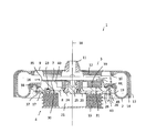
図1に示すように、空気ばね1は、例えば、鉄道車両の車体側と車輪側との間に介在して振動を抑制すると共に、車輪が摩耗した際に、空気を給排気して正規の車体高さに調整するためのものであり、筒状のゴム膜からなるベローズ2の上端部に、車体側に取り付けられる上部材3を止着して、ベローズ2の下端部に、車輪側に取り付けられる下部材4を止着し、その上部材3及び下部材4に、互いに当接して上部材3の上下方向の変位量を制限するストッパ面5、6を形成した構造とされ、さらに、その下部材4に、上下動して下部材4のストッパ面6の高さを調整可能な可動体7と、可動体7を上下動可能に保持する保持体8とを備えたものである。
As shown in FIG. 1, for example, the air spring 1 is interposed between a vehicle body side and a wheel side of a railway vehicle to suppress vibrations, and when a wheel is worn, the air spring 1 supplies and exhausts air. For adjusting the height of the vehicle body, an upper member 3 attached to the vehicle body side is fixed to the upper end portion of the bellows 2 made of a cylindrical rubber film, and the lower end portion of the bellows 2 is attached to the wheel side. The lower member 4 to be attached is fixed, and the upper member 3 and the lower member 4 are formed with stopper surfaces 5 and 6 that abut against each other and limit the amount of displacement of the upper member 3 in the vertical direction. The lower member 4 includes a movable body 7 that can move up and down to adjust the height of the stopper surface 6 of the lower member 4 and a holding body 8 that holds the movable body 7 so as to be movable up and down.
上部材3は、例えば鋼製で円形の上面板9に、その下面からリング状に突出するゴム座10を設けると共に、上面板9の中央部に、上側に突出して加圧空気供給部(図示せず)に連結される連結部11を設けた構造とされる。ゴム座10は、例えばリング状の金属片をゴムで覆ってなり、このゴム座10をベローズ2の上端部に内嵌することにより、ベローズ2の上端部に上部材3が止着されると共に、ゴム座10とベローズ2との間がシールされ、連結部11を介してベローズ2に空気を給排気可能とされる。
The upper member 3 is made of, for example, steel and has a circular upper surface plate 9 provided with a rubber seat 10 that protrudes in a ring shape from the lower surface thereof. It is set as the structure which provided the connection part 11 connected to (not shown). The rubber seat 10 is formed, for example, by covering a ring-shaped metal piece with rubber. By fitting the rubber seat 10 into the upper end portion of the bellows 2, the upper member 3 is fixed to the upper end portion of the bellows 2. The space between the rubber seat 10 and the bellows 2 is sealed, and air can be supplied to and exhausted from the bellows 2 through the connecting portion 11.
上面板9の下面のうち、ゴム座10よりも内側かつ連結部11の周囲には、ゴム製の上ストッパ12が設けられ、この上ストッパ12の下面がストッパ面5とされる。ストッパ面5は、径方向と平行な複数の溝が形成された凹凸状とされ、その溝が、空気が抜けて両ストッパ面5、6が接触した空気ばね1に空気を給入する際の連結部11からベローズ2への空気の通り道とされる。
A rubber upper stopper 12 is provided on the lower surface of the upper surface plate 9 inside the rubber seat 10 and around the connecting portion 11, and the lower surface of the upper stopper 12 serves as the stopper surface 5. The stopper surface 5 has an uneven shape in which a plurality of grooves parallel to the radial direction are formed. The grooves are used when air is supplied to the air spring 1 where the stopper surfaces 5 and 6 are in contact with each other. An air passage from the connecting portion 11 to the bellows 2 is used.
上面板9の周縁部には、下向きに突出する筒部13が形成され、この筒部13が、下端部を上向きかつ内側に押し込むように折り返されると共に給気されたベローズ2の膨みを規制する。筒部13の内面はゴム14で覆われ、上部材3が水平方向に変位する際のベローズ2の摩耗を軽減するようになっている。
A cylindrical portion 13 that protrudes downward is formed at the peripheral edge of the upper surface plate 9, and the cylindrical portion 13 is folded back so as to push the lower end portion upward and inward, and the swelling of the bellows 2 supplied with air is restricted. To do. The inner surface of the cylindrical portion 13 is covered with rubber 14 so as to reduce wear of the bellows 2 when the upper member 3 is displaced in the horizontal direction.
下部材4は、上ストッパ12に当接して上部材3の変位量を制限する下ストッパ16をばね座17に取り付けて、このばね座17を積層ゴム15の上面側に止着した構造とされる。
The lower member 4 has a structure in which a lower stopper 16 that is in contact with the upper stopper 12 and restricts the amount of displacement of the upper member 3 is attached to a spring seat 17, and the spring seat 17 is fixed to the upper surface side of the laminated rubber 15. The
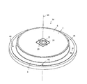
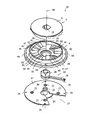
図1~図5に示すように、下ストッパ16は、ばね座17に止着される保持体8と、保持体8が保持する可動体7と、可動体7を中心軸18の周りに回転させるハンドル19とから構成される。
As shown in FIGS. 1 to 5, the lower stopper 16 includes a holding body 8 fixed to the spring seat 17, a movable body 7 held by the holding body 8, and the movable body 7 rotating around a central axis 18. And a handle 19 to be moved.
ばね座17は、例えば鋼製の円板状とされ、下面に形成された円形のずれ止め20を積層ゴム15の中央穴21に係合させると共に、ボルト孔22にボルト23を挿通して積層ゴム15にボルト固定される。このばね座17には、中心から上側に突出してハンドル19のボス部24を支持する支持軸25が形成されると共に、ハンドル19のアーム26を位置させるための切欠27が例えば中心角が60°程度の扇形状に形成されている。
The spring seat 17 is made of, for example, a steel disk. The circular seat stopper 20 formed on the lower surface is engaged with the central hole 21 of the laminated rubber 15, and the bolt 23 is inserted into the bolt hole 22 to be laminated. It is bolted to the rubber 15. The spring seat 17 is formed with a support shaft 25 that protrudes upward from the center and supports the boss portion 24 of the handle 19, and a notch 27 for positioning the arm 26 of the handle 19 has a central angle of 60 °, for example. It is formed in a fan shape.
ハンドル19は、アーム26の基端部に可動体7に係合するボス部24を設けてなり、先端部を操作して可動体7を中心軸18の周りに回転移動させると共に、先端部に設けられた固定部としてのピン孔28を保持体8に固定して、可動体7の回転を阻止するようになっている。
The handle 19 is provided with a boss portion 24 that engages the movable body 7 at the base end portion of the arm 26, operates the distal end portion to rotate the movable body 7 around the central axis 18, and at the distal end portion. A pin hole 28 as a fixed portion provided is fixed to the holding body 8 to prevent the movable body 7 from rotating.
可動体7は、例えばアルミニウムなどの金属や合成樹脂からなる円盤状で、中央部に、ハンドル19のボス部20に嵌合される嵌合穴29が形成され、この可動体7の上面が平面状のストッパ面6とされる。可動体7の下面側には、その複数箇所に可動体7の下面30から下側に突出する水平面31が形成され、可動体7の下面30と各水平面31とを繋ぐように、水平面に対して可動体7の周方向に傾斜する複数のテーパー32と中間水平面33とが交互に形成されている。
The movable body 7 has a disc shape made of, for example, a metal such as aluminum or a synthetic resin, and a fitting hole 29 is formed in the center portion to be fitted to the boss portion 20 of the handle 19, and the upper surface of the movable body 7 is flat. A stopper surface 6 is formed. On the lower surface side of the movable body 7, horizontal surfaces 31 projecting downward from the lower surface 30 of the movable body 7 are formed at a plurality of locations, and the lower surface 30 of the movable body 7 and each horizontal surface 31 are connected with respect to the horizontal surface. Thus, a plurality of tapers 32 and intermediate horizontal surfaces 33 that are inclined in the circumferential direction of the movable body 7 are alternately formed.
保持体8は、例えばアルミニウムなどの金属や合成樹脂からなる円盤状とされ、その中央部に、ばね座17の支持軸25及びハンドル19のボス部24を貫通させる貫通穴34が形成され、上面側に、可動体7を上下動自在かつ中心軸18の周りに回転自在に保持する筒部35が形成されている。
The holding body 8 is formed into a disk shape made of a metal such as aluminum or a synthetic resin, for example, and a through hole 34 is formed in the center portion thereof so as to penetrate the support shaft 25 of the spring seat 17 and the boss portion 24 of the handle 19. On the side, a cylindrical portion 35 is formed that holds the movable body 7 up and down and rotatable around the central axis 18.
この保持体8は、ばね座17との間に、支持軸25に外嵌したハンドル19のボス部24を介在させると共に、ボルト孔36に挿通されてねじ孔46に螺合されるボルト37によって、ばね座17にボルト固定される。保持体8の筒部35よりも外周側にはゴム座38が設けられ、保持体8が、ベローズ2の下端部を止着してシールするビードシートとしても機能する。
The holding body 8 is interposed between the spring seat 17 and a boss portion 24 of the handle 19 that is externally fitted to the support shaft 25, and a bolt 37 that is inserted into the bolt hole 36 and screwed into the screw hole 46. The bolt is fixed to the spring seat 17. A rubber seat 38 is provided on the outer peripheral side of the cylindrical portion 35 of the holding body 8, and the holding body 8 also functions as a bead sheet that fastens and seals the lower end portion of the bellows 2.
保持体8の上面側かつ筒部35の内側には、その複数箇所に保持体8の上面39から上側に突出する水平面40が形成され、保持体8の上面39と各水平面40とを繋ぐように、水平面に対して可動体7の周方向に傾斜する複数のテーパー41と中間水平面42とが交互に形成されている。
Horizontal surfaces 40 protruding upward from the upper surface 39 of the holding body 8 are formed at a plurality of locations on the upper surface side of the holding body 8 and inside the cylindrical portion 35 so as to connect the upper surface 39 of the holding body 8 and each horizontal surface 40. In addition, a plurality of tapers 41 and intermediate horizontal planes 42 that are inclined in the circumferential direction of the movable body 7 with respect to the horizontal plane are alternately formed.
保持体8の筒部35に可動体7が挿入され、可動体7の下面30、水平面31、テーパー32及び中間水平面33と、保持体8の水平面40、上面39、テーパー41及び中間水平面42とが噛合っている。可動体7のテーパー32と保持体8のテーパー41とは、互いに摺動可能とされ、ハンドル19を操作して可動体7を中心軸18の回りに回転させることにより、可動体7が上下方向に移動するようになっている。
The movable body 7 is inserted into the cylindrical portion 35 of the holding body 8. The lower surface 30, the horizontal surface 31, the taper 32 and the intermediate horizontal surface 33 of the movable body 7, and the horizontal surface 40, the upper surface 39, the taper 41 and the intermediate horizontal surface 42 of the holding body 8 Are engaged. The taper 32 of the movable body 7 and the taper 41 of the holding body 8 are slidable with each other, and the movable body 7 is moved in the vertical direction by operating the handle 19 and rotating the movable body 7 around the central axis 18. To move to.
保持体8の水平面40、上面39及び中間水平面42に、可動体7の下面30、水平面31及び中間水平面33が乗り上げた複数の状態で、可動体7が高さ方向に位置決めされる。
The movable body 7 is positioned in the height direction in a plurality of states in which the lower surface 30, the horizontal plane 31 and the intermediate horizontal plane 33 of the movable body 7 ride on the horizontal plane 40, the upper surface 39 and the intermediate horizontal plane 42 of the holding body 8.
保持体8の下面には、ハンドル19のピン孔28に挿通したピン43を挿入する複数のピン挿入孔44が形成され、可動体7が高さ方向に位置決めされた状態で、ハンドル19を保持体8に対して固定するようになっている。ピン孔28に挿通したピン43は、割りピン45によってピン孔28からの脱落が阻止される。
A plurality of pin insertion holes 44 for inserting pins 43 inserted into the pin holes 28 of the handle 19 are formed on the lower surface of the holding body 8, and the handle 19 is held in a state where the movable body 7 is positioned in the height direction. It is designed to be fixed with respect to the body 8. The pin 43 inserted into the pin hole 28 is prevented from dropping from the pin hole 28 by the split pin 45.
次に、下ストッパの動作を説明する。図6に示すように、ばね座17の下側から、その切欠27から露出するハンドル19を操作して、ばね座17の支持軸25の周りにハンドル19のボス部24を回転させる。これにより、ボス部24と嵌合穴29で係合する可動体7が中心軸18の回りに回転し、可動体7のテーパー32と保持体8のテーパー41とが互いに摺動して、可動体7が回転しながら上下方向に移動し、下側のストッパ面6の高さが変化する。
Next, the operation of the lower stopper will be described. As shown in FIG. 6, the handle 19 exposed from the notch 27 is operated from the lower side of the spring seat 17 to rotate the boss portion 24 of the handle 19 around the support shaft 25 of the spring seat 17. As a result, the movable body 7 engaged with the boss portion 24 and the fitting hole 29 rotates around the central axis 18, and the taper 32 of the movable body 7 and the taper 41 of the holding body 8 slide relative to each other to move. The body 7 moves up and down while rotating, and the height of the lower stopper surface 6 changes.
可動体7は、その下面30が保持体8の上面39に載置された状態(a-1、b-1)と、下面30が保持体8の水平面40に載置された状態(a-4、b-4)との間で移動し、その間、下面30が保持体8の中間水平面42に載置された状態(a-2、b-2)、(a-3、b-3)で一旦位置決めされる。
The movable body 7 has a lower surface 30 placed on the upper surface 39 of the holding body 8 (a-1, b-1) and a lower surface 30 placed on the horizontal surface 40 of the holding body 8 (a- 4 and b-4) while the lower surface 30 is placed on the intermediate horizontal surface 42 of the holding body 8 (a-2, b-2), (a-3, b-3) Is once positioned.
可動体7を高さ方向に位置決めして、下側のストッパ面6を所望の高さに調整した状態において、ハンドル19のピン孔28の位置が保持体8の下面のピン挿入孔44の位置に対応するようになっている。ピン孔28及びピン挿入孔44にピン43を挿入し、ピン43の脱落を割りピン45で阻止して、可動体7の上下動を規制し、下側のストッパ面6の高さ調整が完了する。
In a state where the movable body 7 is positioned in the height direction and the lower stopper surface 6 is adjusted to a desired height, the position of the pin hole 28 of the handle 19 is the position of the pin insertion hole 44 on the lower surface of the holding body 8. It comes to correspond to. The pin 43 is inserted into the pin hole 28 and the pin insertion hole 44, the pin 43 is prevented from falling off by the split pin 45, the vertical movement of the movable body 7 is restricted, and the height adjustment of the lower stopper surface 6 is completed. To do.
上記構成によれば、ばね座17の下側からハンドル19を操作して、ストッパ面6の高さを調整することができるので、空気ばね1の上から車体を取り外すことなく、容易にストッパ間隔を調整することができる。
According to the above configuration, the height of the stopper surface 6 can be adjusted by operating the handle 19 from the lower side of the spring seat 17, so that the stopper interval can be easily removed without removing the vehicle body from above the air spring 1. Can be adjusted.
また、下側のストッパ面6を平面状に形成しているので、空気ばね1が水平方向に変位して、上部材3と下部材4との中心位置がずれたとしても、両ストッパ面5、6の間隔が変化することはなく、設定通りのストッパ間隔を維持することができる。しかも、下側のストッパ面6が平面状であり、ストッパ面5、6が突出部の狭い面積で当接することがなく、ストッパ面5、6の損傷を防止することができる。
Further, since the lower stopper surface 6 is formed in a flat shape, even if the air spring 1 is displaced in the horizontal direction and the center positions of the upper member 3 and the lower member 4 are displaced, both the stopper surfaces 5 , 6 does not change, and the stopper interval as set can be maintained. In addition, the lower stopper surface 6 is flat, and the stopper surfaces 5 and 6 do not come into contact with each other in a narrow area of the protruding portion, so that damage to the stopper surfaces 5 and 6 can be prevented.
なお、本発明は、上記の実施の形態に限定されるものではなく、本発明の範囲内において、適宜変更を加えることができる。例えば、空気ばね1は、鉄道車両用のものに限らず、他の用途に用いられるものであってもよい。また、保持体8とばね座17とは、別体に形成することなく、これらを一体に形成することもできる。
In addition, this invention is not limited to said embodiment, A change can be suitably added within the scope of the present invention. For example, the air spring 1 is not limited to one for a rail vehicle, and may be used for other purposes. Further, the holding body 8 and the spring seat 17 can be integrally formed without being formed separately.
可動体7は、保持体8に対して中心軸18の周りに相対的に回転可能であればよく、可動体7に代えて保持体8を回転させるようにしてもよい。また、テーパー32、41は、可動体7及び保持体8のうちの少なくとも一方に形成すればよく、テーパー32、41のうちの一方のみを形成するようにしてもよい。
The movable body 7 only needs to be rotatable around the central axis 18 with respect to the holding body 8, and the holding body 8 may be rotated instead of the movable body 7. Further, the tapers 32 and 41 may be formed on at least one of the movable body 7 and the holding body 8, and only one of the tapers 32 and 41 may be formed.
ストッパ面5、6は、少なくとも一方を平面状に形成すればよく、下側のストッパ面6を平面状に形成する代わりに、上側のストッパ面5のみを平面状にしてもよく、両ストッパ面5、6を平面状にしてもよい。
At least one of the stopper surfaces 5 and 6 may be formed in a flat shape. Instead of forming the lower stopper surface 6 in a flat shape, only the upper stopper surface 5 may be formed in a flat shape. 5 and 6 may be planar.
テーパー32、41を複数形成して、可動体7を高さ方向に位置決めする中間水平面33、42を設ける代わりに、一つのテーパーのみを形成し、可動体7を無段階で位置決めすることもできる。この場合、上下方向に作用する力の一部がテーパーによって周方向に作用する力に変換されるが、ハンドル19を例えば保持体8に固定して可動体7の回転を阻止することにより、可動体7の上下方向の移動を阻止することができる。
Instead of forming a plurality of tapers 32 and 41 and providing intermediate horizontal surfaces 33 and 42 for positioning the movable body 7 in the height direction, it is possible to form only one taper and position the movable body 7 in a stepless manner. . In this case, a part of the force acting in the vertical direction is converted into a force acting in the circumferential direction by the taper. However, the handle 19 is fixed to the holding body 8 to prevent the movable body 7 from rotating. The vertical movement of the body 7 can be prevented.
本発明に係る空気ばねは、例えば鉄道車両の車輪側と車体側との間に介在させて振動を抑制しつつ、そのストッパで上下方向の変位量を制限する用途に好適に採用することができる。
The air spring according to the present invention can be suitably used for, for example, an application in which the amount of displacement in the vertical direction is limited by the stopper while suppressing vibration by being interposed between the wheel side and the vehicle body side of a railway vehicle. .
1 空気ばね
2 ベローズ
3 上部材
4 下部材
5 ストッパ面
6 ストッパ面
7 可動体
8 保持体
9 上面板
10 ゴム座
11 連結部
12 上ストッパ
13 筒部
14 ゴム
15 積層ゴム
16 下ストッパ
17 ばね座
18 中心軸
19 ハンドル
20 ずれ止め
21 中央穴
22 ボルト孔
23 ボルト
24 ボス部
25 支持軸
26 アーム
27 切欠
28 ピン孔
29 嵌合穴
30 下面
31 水平面
32 テーパー
33 中間水平面
34 貫通穴
35 筒部
36 ボルト孔
37 ボルト
38 ゴム座
39 上面
40 水平面
41 テーパー
42 中間水平面
43 ピン
44 ピン挿入孔
45 割りピン
46 ねじ孔 DESCRIPTION OFSYMBOLS 1 Air spring 2 Bellows 3 Upper member 4 Lower member 5 Stopper surface 6 Stopper surface 7 Movable body 8 Holding body 9 Upper surface board 10 Rubber seat 11 Connection part 12 Upper stopper 13 Cylindrical part 14 Rubber 15 Laminated rubber 16 Lower stopper 17 Spring seat 18 Center shaft 19 Handle 20 Slip stop 21 Central hole 22 Bolt hole 23 Bolt 24 Boss portion 25 Support shaft 26 Arm 27 Notch 28 Pin hole 29 Fitting hole 30 Lower surface 31 Horizontal surface 32 Taper 33 Intermediate horizontal surface 34 Through hole 35 Tube portion 36 Bolt hole 37 Bolt 38 Rubber seat 39 Upper surface 40 Horizontal surface 41 Taper 42 Intermediate horizontal surface 43 Pin 44 Pin insertion hole 45 Split pin 46 Screw hole
2 ベローズ
3 上部材
4 下部材
5 ストッパ面
6 ストッパ面
7 可動体
8 保持体
9 上面板
10 ゴム座
11 連結部
12 上ストッパ
13 筒部
14 ゴム
15 積層ゴム
16 下ストッパ
17 ばね座
18 中心軸
19 ハンドル
20 ずれ止め
21 中央穴
22 ボルト孔
23 ボルト
24 ボス部
25 支持軸
26 アーム
27 切欠
28 ピン孔
29 嵌合穴
30 下面
31 水平面
32 テーパー
33 中間水平面
34 貫通穴
35 筒部
36 ボルト孔
37 ボルト
38 ゴム座
39 上面
40 水平面
41 テーパー
42 中間水平面
43 ピン
44 ピン挿入孔
45 割りピン
46 ねじ孔 DESCRIPTION OF
Claims (5)
- ベローズの上下端部にそれぞれ上部材及び下部材を止着してなり、前記上部材及び下部材に、互いに当接して上部材の変位量を制限するストッパ面が形成された空気ばねであって、前記下部材は、上下動して当該下部材のストッパ面の高さを調整可能な可動体と、該可動体を上下動可能に保持する保持体とを備え、前記可動体は、保持体に対して中心軸周りに相対的に回転可能とされ、前記可動体及び保持体のうちの少なくとも一方に、他方に対して摺動可能なテーパーが水平面に対して可動体の周方向に傾斜して形成されたことを特徴とする空気ばね。 An air spring comprising an upper member and a lower member fixed to upper and lower ends of the bellows, respectively, and a stopper face that is in contact with each other and limits the amount of displacement of the upper member. The lower member includes a movable body that can move up and down to adjust the height of the stopper surface of the lower member, and a holding body that holds the movable body so as to be movable up and down. And a taper that is slidable relative to the horizontal plane is inclined in the circumferential direction of the movable body with respect to at least one of the movable body and the holding body. An air spring characterized by being formed.
- 前記上部材及び下部材のうち、少なくとも一方のストッパ面が平面状に形成されたことを特徴とする請求項1に記載の空気ばね。 The air spring according to claim 1, wherein at least one stopper surface of the upper member and the lower member is formed in a flat shape.
- 前記テーパーが複数形成され、各テーパー間に、前記可動体を高さ方向に位置決めする水平面が設けられたことを特徴とする請求項1に記載の空気ばね。 The air spring according to claim 1, wherein a plurality of the tapers are formed, and a horizontal surface for positioning the movable body in a height direction is provided between the respective tapers.
- 前記可動体及び保持体のうちの一方を回転させるハンドルが設けられ、該ハンドルを他方に対して固定する固定部が設けられたことを特徴とする請求項1、2又は3に記載の空気ばね。 The air spring according to claim 1, 2 or 3, wherein a handle for rotating one of the movable body and the holding body is provided, and a fixing portion for fixing the handle to the other is provided. .
- 空気ばねの下部材に設けられ、空気ばねの上部材に当接して上部材の変位量を制限する空気ばね用ストッパであって、上下動して前記下部材のストッパ面の高さを調整可能な可動体と、該可動体を上下動可能に保持する保持体とを備え、前記可動体は、保持体に対して中心軸周りに相対的に回転可能とされ、前記可動体及び保持体のうちの少なくとも一方に、他方に対して摺動可能なテーパーが水平面に対して可動体の周方向に傾斜して形成されたことを特徴とする空気ばね用ストッパ。 An air spring stopper provided on the lower member of the air spring and contacting the upper member of the air spring to limit the amount of displacement of the upper member. The height of the stopper surface of the lower member can be adjusted by moving up and down. A movable body and a holding body that holds the movable body so as to be movable up and down. The movable body is rotatable relative to the holding body around a central axis, and the movable body and the holding body A stopper for an air spring, wherein at least one of them has a taper slidable with respect to the other inclined with respect to a horizontal plane in the circumferential direction of the movable body.
Priority Applications (3)
| Application Number | Priority Date | Filing Date | Title |
|---|---|---|---|
| CN201180061510.4A CN103270332B (en) | 2011-01-07 | 2011-03-28 | Air spring |
| US13/978,634 US9061689B2 (en) | 2011-01-07 | 2011-03-28 | Air spring |
| EP11855016.9A EP2662590B8 (en) | 2011-01-07 | 2011-03-28 | Air spring |
Applications Claiming Priority (2)
| Application Number | Priority Date | Filing Date | Title |
|---|---|---|---|
| JP2011001950A JP5670760B2 (en) | 2011-01-07 | 2011-01-07 | Air spring |
| JP2011-001950 | 2011-01-31 |
Publications (1)
| Publication Number | Publication Date |
|---|---|
| WO2012093501A1 true WO2012093501A1 (en) | 2012-07-12 |
Family
ID=46457366
Family Applications (1)
| Application Number | Title | Priority Date | Filing Date |
|---|---|---|---|
| PCT/JP2011/057613 WO2012093501A1 (en) | 2011-01-07 | 2011-03-28 | Air spring |
Country Status (6)
| Country | Link |
|---|---|
| US (1) | US9061689B2 (en) |
| EP (1) | EP2662590B8 (en) |
| JP (1) | JP5670760B2 (en) |
| CN (1) | CN103270332B (en) |
| TW (1) | TWI513923B (en) |
| WO (1) | WO2012093501A1 (en) |
Families Citing this family (20)
| Publication number | Priority date | Publication date | Assignee | Title |
|---|---|---|---|---|
| JP5912898B2 (en) * | 2012-06-18 | 2016-04-27 | 川崎重工業株式会社 | Railcar bogie |
| US9278699B2 (en) * | 2013-01-08 | 2016-03-08 | Firestone Industrial Products Company, Llc | Lateral support elements, gas spring assemblies and methods |
| WO2014127344A2 (en) * | 2013-02-18 | 2014-08-21 | Firestone Industrial Products Company, Llc | End member assemblies as well as gas spring assemblies and methods of manufacture including same |
| JP6159186B2 (en) * | 2013-07-31 | 2017-07-05 | 川崎重工業株式会社 | Air spring and railway vehicle |
| JP6345450B2 (en) * | 2014-03-14 | 2018-06-20 | 住友電気工業株式会社 | Air spring |
| JP6424086B2 (en) * | 2014-12-26 | 2018-11-14 | 東洋ゴム工業株式会社 | Air spring |
| EP3245419A1 (en) * | 2015-01-12 | 2017-11-22 | Firestone Industrial Products Company, LLC | Lateral support elements, gas spring assemblies, suspension systems and methods |
| DE102016100581A1 (en) * | 2016-01-14 | 2017-07-20 | Bpw Bergische Achsen Kg | Air spring for axles of air-suspended vehicles |
| JP6605986B2 (en) * | 2016-02-24 | 2019-11-13 | 東海旅客鉄道株式会社 | Vehicle body tilt control device and failure determination device for vehicle body tilt control device |
| US10538257B2 (en) * | 2016-10-17 | 2020-01-21 | Sumitomo Electric Industries, Ltd. | Air spring and bogie |
| CN109844359B (en) * | 2016-10-17 | 2021-04-23 | 住友电气工业株式会社 | Air spring and bogie |
| US10449979B2 (en) | 2016-10-17 | 2019-10-22 | Sumitomo Electric Industries, Ltd. | Air spring and bogie |
| SG11201903361UA (en) | 2016-10-17 | 2019-05-30 | Sumitomo Electric Industries | Air spring and bogie |
| US10597050B2 (en) | 2016-10-17 | 2020-03-24 | Sumitomo Electric Industries, Ltd. | Air spring and bogie |
| CN107701642B (en) * | 2017-10-27 | 2021-03-23 | 株洲时代新材料科技股份有限公司 | Pre-pressing type emergency air spring assembly |
| CN107740833A (en) * | 2017-10-27 | 2018-02-27 | 株洲时代新材料科技股份有限公司 | Hourglass air spring assembly |
| JP7094130B2 (en) * | 2018-03-28 | 2022-07-01 | 住友理工株式会社 | Railroad vehicle stopper |
| TWI764746B (en) * | 2021-06-04 | 2022-05-11 | 中台橡膠工業股份有限公司 | Air spring for secondary suspension system |
| TWI772052B (en) * | 2021-06-04 | 2022-07-21 | 中台橡膠工業股份有限公司 | Application of air spring with stop device |
| DE102022130802B3 (en) | 2022-11-22 | 2023-08-24 | Dr. Ing. H.C. F. Porsche Aktiengesellschaft | Suspension strut for a motor vehicle with an adjustment device for adjusting a spring force |
Citations (4)
| Publication number | Priority date | Publication date | Assignee | Title |
|---|---|---|---|---|
| JPH0989029A (en) | 1995-09-27 | 1997-03-31 | Bridgestone Corp | Pneumatic spring having up-and-down moving stopper |
| JP2000035075A (en) * | 1998-07-16 | 2000-02-02 | Sumitomo Electric Ind Ltd | Air spring |
| JP2000088030A (en) * | 1998-09-11 | 2000-03-28 | Sumitomo Metal Ind Ltd | Air spring and its height adjusting device |
| JP2010076608A (en) * | 2008-09-26 | 2010-04-08 | Toyo Tire & Rubber Co Ltd | Air spring and height adjustment method for railway vehicle |
Family Cites Families (14)
| Publication number | Priority date | Publication date | Assignee | Title |
|---|---|---|---|---|
| US3069149A (en) * | 1960-05-31 | 1962-12-18 | Gen Motors Corp | Coil spring suspension with auxiliary overload bumper |
| US5921532A (en) * | 1994-10-07 | 1999-07-13 | Neway Anchorlok International, Inc. | Air spring with internal support member |
| CN2227166Y (en) * | 1995-03-17 | 1996-05-15 | 傅博 | Adjustable rooting basement |
| DE19539151A1 (en) * | 1995-10-20 | 1997-04-24 | Fichtel & Sachs Ag | Vehicle pneumatic suspension element |
| DE19935865B4 (en) * | 1999-07-30 | 2009-10-22 | Audi Ag | Device for changing the spring rate |
| US6820883B2 (en) * | 2001-11-07 | 2004-11-23 | Meritor Heavy Vehicle Technology Llc | Vehicle suspension including dock height holding device |
| CN2654696Y (en) | 2003-11-05 | 2004-11-10 | 天津五市政公路工程有限公司 | Multifunction regulable manhole |
| US7150451B2 (en) * | 2005-02-18 | 2006-12-19 | Gm Global Technology Operations, Inc. | Air spring and jounce shock assembly |
| US7284644B2 (en) * | 2005-03-16 | 2007-10-23 | Bfs Diversified Products, Llc | Multiple load path air spring assembly |
| US7500659B2 (en) * | 2005-04-07 | 2009-03-10 | Bfs Diversified Products, Llc | Air spring assembly and method |
| US8317172B2 (en) * | 2007-01-25 | 2012-11-27 | GM Global Technology Operations LLC | Multistage jounce bumper |
| US8272653B2 (en) * | 2009-06-23 | 2012-09-25 | Teraflex, Inc. | Structures, assemblies, and methods for controlling vehicle suspension |
| AT515230B1 (en) * | 2011-07-08 | 2016-05-15 | Toyo Tire & Rubber Co | Air spring for rail vehicle |
| US8950764B2 (en) * | 2012-01-29 | 2015-02-10 | Firestone Industrial Products Company, Llc | Jounce bumper, end member, gas spring assembly and method of assembly |
-
2011
- 2011-01-07 JP JP2011001950A patent/JP5670760B2/en not_active Expired - Fee Related
- 2011-02-17 TW TW100105245A patent/TWI513923B/en not_active IP Right Cessation
- 2011-03-28 EP EP11855016.9A patent/EP2662590B8/en active Active
- 2011-03-28 CN CN201180061510.4A patent/CN103270332B/en not_active Expired - Fee Related
- 2011-03-28 WO PCT/JP2011/057613 patent/WO2012093501A1/en active Application Filing
- 2011-03-28 US US13/978,634 patent/US9061689B2/en not_active Expired - Fee Related
Patent Citations (4)
| Publication number | Priority date | Publication date | Assignee | Title |
|---|---|---|---|---|
| JPH0989029A (en) | 1995-09-27 | 1997-03-31 | Bridgestone Corp | Pneumatic spring having up-and-down moving stopper |
| JP2000035075A (en) * | 1998-07-16 | 2000-02-02 | Sumitomo Electric Ind Ltd | Air spring |
| JP2000088030A (en) * | 1998-09-11 | 2000-03-28 | Sumitomo Metal Ind Ltd | Air spring and its height adjusting device |
| JP2010076608A (en) * | 2008-09-26 | 2010-04-08 | Toyo Tire & Rubber Co Ltd | Air spring and height adjustment method for railway vehicle |
Also Published As
| Publication number | Publication date |
|---|---|
| US20130313764A1 (en) | 2013-11-28 |
| CN103270332A (en) | 2013-08-28 |
| EP2662590B1 (en) | 2019-10-16 |
| EP2662590A4 (en) | 2018-01-24 |
| JP2012145135A (en) | 2012-08-02 |
| EP2662590B8 (en) | 2019-11-20 |
| US9061689B2 (en) | 2015-06-23 |
| JP5670760B2 (en) | 2015-02-18 |
| CN103270332B (en) | 2015-07-01 |
| EP2662590A1 (en) | 2013-11-13 |
| TWI513923B (en) | 2015-12-21 |
| TW201229402A (en) | 2012-07-16 |
Similar Documents
| Publication | Publication Date | Title |
|---|---|---|
| JP5670760B2 (en) | Air spring | |
| JP4681327B2 (en) | Automatic balance adjustment device | |
| JP5089534B2 (en) | Levitation unit and non-contact support device having the same | |
| US7648207B2 (en) | Rotating structure for armrests | |
| JP2006321481A5 (en) | ||
| KR101299907B1 (en) | Inner diameter adjustable jig for transfer unit | |
| JP5517351B2 (en) | Air spring with stopper | |
| KR20080009038A (en) | Piston-cylinder unit with a protective sleeve | |
| JP2017512519A (en) | Amusement park apparatus having a rail-guided route course and having at least one vehicle guided on the rail | |
| CN107088679B (en) | A kind of oblique pull cutting machine | |
| JP2016540945A (en) | Belt tensioner for drive belt | |
| US10717161B2 (en) | Rotating axis supporting device | |
| TWI758339B (en) | Air spring and bogie | |
| JP2004244010A (en) | Adjuster with caster | |
| CN110730724A (en) | Caster wheel rotation limiting structure | |
| JP5228875B2 (en) | Hi-hat cymbal angle adjustment structure | |
| KR101280909B1 (en) | Chair folding device for table attached chair | |
| JP2014134289A (en) | Pneumatic spring | |
| JP2019044434A (en) | Railroad rail correcting vehicle | |
| JP3201614U (en) | Gas cylinder structure | |
| TWM469401U (en) | Shock absorber damping adjustment set | |
| KR100961969B1 (en) | Honing tool | |
| JP2023085983A (en) | Automobile testing device | |
| JP2005320173A (en) | Lifting device | |
| KR20140003075U (en) | Step height adjustment device for hull block assembly |
Legal Events
| Date | Code | Title | Description |
|---|---|---|---|
| 121 | Ep: the epo has been informed by wipo that ep was designated in this application |
Ref document number: 11855016 Country of ref document: EP Kind code of ref document: A1 |
|
| NENP | Non-entry into the national phase |
Ref country code: DE |
|
| WWE | Wipo information: entry into national phase |
Ref document number: 2011855016 Country of ref document: EP |
|
| WWE | Wipo information: entry into national phase |
Ref document number: 13978634 Country of ref document: US |