WO2018073860A1 - Air spring and bogie - Google Patents
Air spring and bogie Download PDFInfo
- Publication number
- WO2018073860A1 WO2018073860A1 PCT/JP2016/080694 JP2016080694W WO2018073860A1 WO 2018073860 A1 WO2018073860 A1 WO 2018073860A1 JP 2016080694 W JP2016080694 W JP 2016080694W WO 2018073860 A1 WO2018073860 A1 WO 2018073860A1
- Authority
- WO
- WIPO (PCT)
- Prior art keywords
- air spring
- protrusion
- inner cylinder
- outer cylinder
- stopper
- Prior art date
Links
Images


Classifications
-
- B—PERFORMING OPERATIONS; TRANSPORTING
- B61—RAILWAYS
- B61F—RAIL VEHICLE SUSPENSIONS, e.g. UNDERFRAMES, BOGIES OR ARRANGEMENTS OF WHEEL AXLES; RAIL VEHICLES FOR USE ON TRACKS OF DIFFERENT WIDTH; PREVENTING DERAILING OF RAIL VEHICLES; WHEEL GUARDS, OBSTRUCTION REMOVERS OR THE LIKE FOR RAIL VEHICLES
- B61F5/00—Constructional details of bogies; Connections between bogies and vehicle underframes; Arrangements or devices for adjusting or allowing self-adjustment of wheel axles or bogies when rounding curves
- B61F5/02—Arrangements permitting limited transverse relative movements between vehicle underframe or bolster and bogie; Connections between underframes and bogies
- B61F5/04—Bolster supports or mountings
- B61F5/10—Bolster supports or mountings incorporating fluid springs
-
- F—MECHANICAL ENGINEERING; LIGHTING; HEATING; WEAPONS; BLASTING
- F16—ENGINEERING ELEMENTS AND UNITS; GENERAL MEASURES FOR PRODUCING AND MAINTAINING EFFECTIVE FUNCTIONING OF MACHINES OR INSTALLATIONS; THERMAL INSULATION IN GENERAL
- F16F—SPRINGS; SHOCK-ABSORBERS; MEANS FOR DAMPING VIBRATION
- F16F9/00—Springs, vibration-dampers, shock-absorbers, or similarly-constructed movement-dampers using a fluid or the equivalent as damping medium
- F16F9/02—Springs, vibration-dampers, shock-absorbers, or similarly-constructed movement-dampers using a fluid or the equivalent as damping medium using gas only or vacuum
- F16F9/04—Springs, vibration-dampers, shock-absorbers, or similarly-constructed movement-dampers using a fluid or the equivalent as damping medium using gas only or vacuum in a chamber with a flexible wall
- F16F9/05—Springs, vibration-dampers, shock-absorbers, or similarly-constructed movement-dampers using a fluid or the equivalent as damping medium using gas only or vacuum in a chamber with a flexible wall the flexible wall being of the rolling diaphragm type
- F16F9/052—Springs, vibration-dampers, shock-absorbers, or similarly-constructed movement-dampers using a fluid or the equivalent as damping medium using gas only or vacuum in a chamber with a flexible wall the flexible wall being of the rolling diaphragm type characterised by the bumper
Definitions
- the present invention relates to an air spring and a carriage.
- air springs using the elasticity of compressed air are known.
- An example of a conventional air spring is described in, for example, Japanese Patent Laid-Open No. 2000-035075.
- the air spring described in this document has a height adjusting mechanism for keeping the amount of compressive deformation (compression stroke) substantially constant.
- the conventional air spring there is an air spring described in JP2012-017769A.
- the air spring described in this publication is an air spring with a stopper provided with a lowering restricting means.
- an air spring described in JP 2012-145135 A can be cited. This air spring is provided with a stopper for limiting the amount of displacement in the vertical direction.
- An air spring includes an outer cylinder, an inner cylinder combined with the outer cylinder, an outer cylinder and an inner cylinder, and a diaphragm that forms an internal space between the outer cylinder and the inner cylinder.
- the air spring is disposed in the inner space so as to be rotatable on the inner cylinder, and a stopper assembly that can prevent the outer cylinder from moving to the inner cylinder more than necessary, and the stopper assembly on the inner cylinder.
- a rotation mechanism is provided for rotation at The stopper assembly has a stopper portion that protrudes toward the outer cylinder side, and the outer cylinder protrudes toward the inner cylinder side and has four or more protruding portions provided at positions facing the stopper portion as a set.
- Each of the projecting portions belonging to the set is arranged continuously and has a different height, and the projecting portion having the lowest height among the projecting portions belonging to the set is the projection of the projecting portion belonging to the set. It arrange
- FIG. 1 is a cross-sectional view of an air spring according to Embodiment 1 of the present invention.
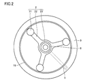
- FIG. 2 is a plan view showing the stopper assembly and the inner cylinder shown in FIG.
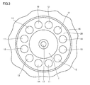
- FIG. 3 is a partial plan view showing the internal structure of the outer cylinder shown in FIG.
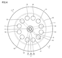
- FIG. 4 is a plan view showing the positional relationship between the stopper assembly shown in FIG. 1 and the protruding portion of the outer cylinder.
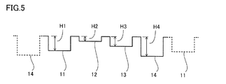
- FIG. 5 is an explanatory diagram showing the arrangement of the protrusions in the first embodiment of the present invention.
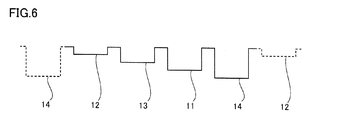
- FIG. 6 is an explanatory diagram showing an arrangement of the protruding portions of the outer cylinder of the air spring in the comparative example.
- FIG. 1 is a cross-sectional view of an air spring according to Embodiment 1 of the present invention.
- FIG. 2 is a plan view showing the stopper assembly and the inner cylinder shown in FIG.
- FIG. 3 is a partial plan view showing the internal structure of the outer cylinder shown in FIG
- FIG. 7 is an explanatory diagram of the positional relationship between the protrusion and the stopper when the outer cylinder of the air spring in the comparative example is close to the inner cylinder.
- FIG. 8 is an explanatory diagram of the positional relationship between the protruding portion and the stopper portion when the outer cylinder of the air spring according to Embodiment 1 of the present invention approaches the inner cylinder.
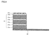
- FIG. 9 is a partial cross-sectional view of the air spring according to Embodiment 2 of the present invention.
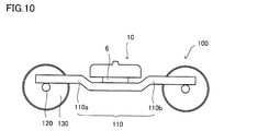
- FIG. 10 is a side view of the carriage according to the third embodiment of the present invention.
- the outer cylinder (6) is provided with a plurality of supported surfaces (6a, 6b, 6c). As shown in FIG. 7 of Patent Document 1, the lowest supported surface (6a) is arranged adjacent to the highest supported surface (6c). In this air spring, the outer cylinder (6) may move not only to the inner cylinder (2) side but also to move horizontally or rotate with respect to the inner cylinder (2). When the position of the stopper is set so that the lowest supported surface (6a) and the raised portion (8b) face each other, the outer cylinder (6) moves to the inner cylinder (2) side.
- the highest supported surface (6c) may be located at a position lower than the upper surface of the raised portion (8b). In this state, when the outer cylinder (6) moves or rotates horizontally with respect to the inner cylinder (2), the side surface of the raised portion (8b) and the side surface of the highest supported surface (6c) collide. There is a possibility.
- the air spring of the present embodiment can solve the problems in the air spring described in Patent Document 1 as described above.
- the air spring according to the present embodiment can be used for various applications such as a suspension device, a vibration isolator, a vehicle height adjustment device, and the like. The vibration transmitted from the wheel to the vehicle can be reduced.
- the air spring of the present embodiment is a self-sealing type air spring, and connects the outer cylinder, the inner cylinder combined with the outer cylinder, the outer cylinder and the inner cylinder, and between the outer cylinder and the inner cylinder. And a diaphragm forming an internal space.
- the outer cylinder and the inner cylinder can be made of a material having rigidity such as metal or fiber reinforced plastic (Fiber Reinforced Plastics).
- the diaphragm can be made of an elastic material such as an elastomer.
- the internal space is a sealed space, and pressurized air is enclosed in the internal space.
- the air spring according to the present embodiment is disposed in the inner space so as to be rotatable on the inner cylinder, and a stopper assembly capable of suppressing the outer cylinder from moving to the inner cylinder more than necessary, and the stopper A rotation mechanism for rotating the assembly on the inner cylinder is also provided.
- the stopper assembly may be manually driven or may be driven by power from a power source.
- the stopper assembly of the air spring of the present embodiment has a stopper portion that protrudes toward the outer cylinder side.
- the outer cylinder of the air spring of the present embodiment has a set of four or more protrusions that protrude to the inner cylinder side and that are provided at positions facing the stopper portion. Each of them is continuously arranged and has a different height, and the projection having the lowest height among the projections belonging to the set is the projection having the highest height among the projections belonging to the set. Arranged not to be adjacent.
- An air spring includes an outer cylinder, an inner cylinder, a diaphragm, a stopper assembly, and a rotation mechanism.
- the inner cylinder is combined with the outer cylinder.
- the diaphragm connects the outer cylinder and the inner cylinder, and forms an internal space between the outer cylinder and the inner cylinder.
- the stopper assembly is disposed in the inner space so as to be rotatable on the inner cylinder, and can prevent the outer cylinder from moving to the inner cylinder more than necessary.
- the stopper assembly has a stopper portion protruding toward the outer cylinder side.
- the outer cylinder has a set of four or more projecting parts projecting toward the inner cylinder side, and each of the projecting parts belonging to the group is continuously arranged and has a different height and belongs to the group.
- the protrusion with the lowest height among the protrusions is arranged so as not to be adjacent to the protrusion with the highest height among the protrusions belonging to the set. Thereby, it can suppress that the side surface of a stopper part and the side surface of a protrusion part collide, and are damaged.
- the protrusion having the lowest height among the protrusions belonging to the set is paired with the protrusion having the second lowest height among the protrusions belonging to the set. You may arrange
- the lowest part among the projecting parts belonging to the set and the projecting part having the highest height among the projecting parts belonging to the set belong to the set.
- the number of protrusions obtained by subtracting 3 from the number of protrusions may be arranged. In this case, since the distance between the lowest protrusion of the protrusions belonging to the set and the highest protrusion of the protrusions belonging to the set is maximized, the side surface of the stopper part and the side surface of the protrusion part Can be further suppressed from colliding and damaging.
- the number of stopper portions may be plural, and the number of sets of protruding portions may be equal to the number of stopper portions.
- the stopper portion includes a rubber layer and a metal layer, and the rubber layer and the metal layer may be alternately arranged.
- an antifriction material may be formed on the upper surface of the stopper portion.
- FIG. 1 shows an air spring according to Embodiment 1 of the present invention.
- the air spring 10 includes an outer cylinder 1, an inner cylinder 9, and a diaphragm 4.
- the outer cylinder 1 includes a top plate, a plurality of projections 11 to 14 projecting from the top plate (projecting toward the inner cylinder 9), and a ring shape rising from the top plate and positioned outside the projections 12 to 14. And a convex portion 16.
- the upper surface plate has a flat plate portion at the center portion and a side wall portion at the peripheral portion.
- a hole is provided in the center of the flat plate portion of the upper surface plate, and the connecting portion 17 is attached to the hole.
- the protrusions 11 to 14 have a cylindrical shape and have different heights as shown in FIG.
- the protrusions 11 to 14 are hollow in the example of FIG. 1, but may be solid.
- the inner cylinder 9 is arranged in a hole portion at the center, a lower surface plate having an upper surface portion around the hole portion, a flange portion 18 rising from the lower surface plate, and an upper surface portion of the lower surface plate.
- the stopper assembly 2 to be operated.
- the stopper assembly 2 includes a plurality of stopper portions 21 having a cylindrical shape, a base portion 22 on which the stopper portions 21 are placed, and a ring portion 23 that is inserted into a hole in the center portion of the lower surface plate.
- the stopper portion 21 has a function of suppressing the outer cylinder 1 from moving to the inner cylinder 9 side by a predetermined amount or more.
- the diaphragm 4 connects the outer cylinder 1 and the inner cylinder 9, and forms an internal space 27 between the outer cylinder 1 and the inner cylinder 9.
- a portion on one end side of the diaphragm 4 extends along the side wall portion and the upper surface plate of the outer cylinder 1, and one end of the diaphragm 4 abuts on the ring-shaped convex portion 16 of the outer cylinder 1.
- the other end of the diaphragm 4 is placed on the peripheral edge of the inner cylinder 9 and abuts on the flange portion 18 of the inner cylinder 9.
- a rubber sheet 26 is disposed between the diaphragm 4 and the peripheral edge of the inner cylinder 9.
- the bottom plate 8 is disposed under the inner cylinder 9.
- the bottom plate 8 has a cylindrical portion at the center, and this cylindrical portion is inserted into the ring portion 23 of the stopper assembly 2.
- a screw hole 33 is provided in the inner cylinder 9, and the bottom plate 8 can be fixed to the inner cylinder 9 by screwing a bolt 28 inserted into the bottom plate 8 into the screw hole 33.
- a lever 5 for rotating the stopper assembly 2 is disposed between the inner cylinder 9 and the bottom plate 8. One end of the lever 5 is fixed to the ring portion 23 by a screw 25, and a handle 7 is attached to the other end of the lever 5 so that the lever 5 can be rotated by hand. Under the bottom plate 8, a laminated rubber 6 is disposed.
- the stopper assembly 2 is appropriately fixed to the inner cylinder 9 or the bottom plate 8 in a state where the stopper portion 21 is rotated so as to face the protruding portions 11 to 14.
- FIG. 2 shows an example of the internal structure of the inner cylinder 9.
- the stopper assembly 2 includes three base portions 22, and the stopper portions 21 are respectively fixed on the outer end portions of the base portions 22.
- the stopper portion 21 protrudes from the base portion 22 toward the outer cylinder 1 side.
- Each of the base parts 22 is arrange
- each of the base portions 22 is arranged with an interval of 120 °. Further, each of the base portions 22 has an equal length.
- the three base portions 22 are simultaneously rotated, and accordingly, the three stopper portions 21 are also simultaneously rotated. At this time, the three base portions 22 slide on the upper surface portion of the lower surface plate of the inner cylinder 9.
- FIG. 3 shows the internal structure of the outer cylinder 1.
- four types of heights 11 to 14 are arranged at equal intervals. These four types of heights 11 to 14 are arranged continuously.
- the four types of projecting portions 11 to 14 having a height form a set.
- the number of protrusions belonging to the set may be four or more.
- Each of the pair of projecting portions 11 to 14 is continuously arranged.
- three sets of four types of protrusions 11 to 14 having different heights are provided. That is, in the example of FIG. 3, a set of protrusions 11 to 14 equal in number to the number of stoppers 21 is provided. Then, as shown in FIG.
- the three protruding portions 12 having the same height are arranged at positions corresponding to the three stopper portions 21.
- the protrusion 11 and the protrusions 13 to 14 are also arranged in the same manner. That is, the arrangement of the protrusions in each set is the same. Thereby, the three stopper portions 21 can be rotated and simultaneously disposed at positions facing the three projecting portions 11 having the same height.
- FIG. 5 schematically shows the arrangement of the protrusions 11 to 14.
- the protrusions 11 to 14 are arranged in the order of the protrusion 11, the protrusion 12, the protrusion 13, and the protrusion 14.
- the protrusion part 11 is adjacent to the protrusion part 14 which belongs to the adjacent group
- the protrusion part 14 is adjacent to the protrusion part 11 which belongs to another adjacent group.
- the protrusion 11 has a height H1.
- the protrusion 12 has a height H2.
- the protrusion 13 has a height H3.
- the protrusion 14 has a height H4.
- the heights H1 to H4 of the protrusions 11 to 14 satisfy the relationship of height H4> height H1> height H3> height H2. That is, the protrusions 11 to 14 are arranged such that the protrusion with the highest height (protrusion 14) is not adjacent to the protrusion with the lowest height (protrusion 12). From another point of view, the protrusion with the lowest height (protrusion 12) is disposed between the protrusions other than the protrusion with the highest height (protrusion 11 and protrusion 13). Yes.
- the protrusion with the lowest height is disposed between the protrusion with the second lowest height (protrusion 13) and the protrusion with the third lowest height (protrusion 11).
- n ⁇ 1 the number of protrusions belonging to the set is 2n (n is an integer of 2 or more) between the protrusions with the lowest height and the protrusions with the highest height. )
- n or n ⁇ 1 when the number of protrusions belonging to the set is 2n + 1)
- the protrusions are preferably disposed.
- FIG. 6 schematically shows the arrangement of the protrusions 11 to 14 in the air spring in the comparative example.
- the protrusions 11 to 14 of the air spring in the comparative example are arranged in the order of the protrusion 12, the protrusion 13, the protrusion 11, and the protrusion 14.
- the protrusion 12 is disposed adjacent to the protrusion 14 belonging to the adjacent set.
- the protrusion 14 is disposed adjacent to the protrusion 12 belonging to another adjacent set. That is, in the air spring in the comparative example, there is a place where the highest protrusion (protrusion 14) is disposed adjacent to the lowest protrusion (protrusion 12).
- FIG. 7 schematically shows the positional relationship between the protruding portions 11 to 14 and the stopper portion 21 when the outer cylinder 1 is close to the inner cylinder 9 in the air spring of the comparative example.
- FIG. 8 schematically shows the positional relationship between the protruding portions 11 to 14 and the stopper portion 21 when the outer cylinder 1 is close to the inner cylinder 9 in the air spring according to the first embodiment. 7 and 8 show a state where the stopper assembly 2 is positioned so that the stopper portion 21 faces the protruding portion 12.
- the protrusion 12 that is the protrusion with the lowest height and the protrusion 14 that is the protrusion with the highest height are arranged adjacent to each other. Therefore, as shown in FIG. 7, when the outer cylinder 1 moves to the inner cylinder 9 side to a position where the stopper portion 21 and the protruding portion 12 approach to a considerable extent, the position of the lower surface of the protruding portion 14 (in the drawing) The one-dot chain line) is lower than the position of the upper surface of the stopper portion (dotted line in the figure).
- the protrusion 12 that is the protrusion with the lowest height is adjacent to the protrusions 11 and 13 that are protrusions other than the protrusion with the highest height. Therefore, as shown in FIG. 8, unless the outer cylinder 1 moves closer to the inner cylinder 9, the lower surfaces of the protruding portions 11 and the protruding portions 13 are not positioned lower than the upper surface of the stopper portion 21. Therefore, in the air spring according to the first embodiment, even if vibration is applied such that the outer cylinder 1 moves horizontally or rotates with respect to the inner cylinder 9, the side surfaces of the protruding portions 11 to 14, the side surfaces of the stopper portion 21, and the like. Is hard to collide. Therefore, in the air spring in the first embodiment, it is possible to suppress the air spring from being damaged, and it is possible to suppress the deterioration of the riding comfort of the vehicle to which the air spring is attached.
- the projecting portion having the lowest height includes the projecting portion having the second lowest height (projecting portion 13) and the projecting portion having the third lowest height (projecting portion). 11), the difference in height between the projections having the lowest height among the projections belonging to the set and the projections adjacent to the projections is minimized. And the side surfaces of the protrusions 11 to 14 can be further prevented from colliding and being damaged.
- n ⁇ 1 the number of protrusions belonging to the set is 2n (where n is 2 or more) between the protrusion with the lowest height and the protrusion with the highest height. Integer)) or n or n-1 (if the number of protrusions belonging to a set is 2n + 1), the lowest protrusion of the protrusions belonging to the set Since the distance between the projecting portion and the projecting portion having the highest height among the projecting portions belonging to the set is maximized, the side surface of the stopper portion and the side surface of the projecting portion can be further prevented from colliding and being damaged.
- the number of sets of the protruding portions 11 to 14 when the number of sets of the protruding portions 11 to 14 is equal to the number of the stopper portions 21, the movement of the outer cylinder 1 toward the inner cylinder 9 is suppressed at a plurality of locations. Therefore, in this case, the movement of the outer cylinder 1 toward the inner cylinder 9 is more reliably suppressed.
- the number of sets of the protrusions 11 to 14 is plural, the number of protrusions increases. As a result, the interval between the protrusions is reduced. That is, when the outer cylinder 1 is subjected to vibration that moves or rotates horizontally with respect to the inner cylinder 9, the side surfaces of the projecting portions 11 to 14 and the side surface of the stopper portion 21 easily collide.
- the air spring according to the first embodiment there is no place where the projecting portion with the highest height (projecting portion 14) is disposed adjacent to the projecting portion with the lowest height (projecting portion 12). Even in such a case, it is possible to prevent the side surfaces of the protruding portions 11 to 14 and the side surfaces of the stopper portion 21 from colliding with each other. Therefore, in this case, the movement of the outer cylinder 1 toward the inner cylinder 9 can be more reliably suppressed, and damage to the air spring and deterioration of the riding comfort of the vehicle to which the air spring is attached can be suppressed. .
- FIG. 9 shows the structure of the stopper portion 21 of the air spring in the second embodiment.
- the stopper portion 21 has a laminated rubber structure. That is, the stopper part 21 has the rubber layer 21a and the metal layer 21b. The rubber layers 21a and the metal layers 21b are alternately arranged in the direction from the bottom surface to the top surface of the stopper portion. A metal layer 21 b is disposed on the upper surface side of the stopper portion 21.
- the stopper portion 21 has higher rigidity against compressive deformation than the case where the stopper portion 21 is configured only by the rubber layer 21a.
- an antifriction material 21c may be provided on the stopper portion 21 (more specifically, on the metal layer 21b disposed on the upper surface side of the stopper 21 portion).
- the antifriction material 21c is a material in which the friction coefficient between the protrusions 11 to 14 is smaller than the friction coefficient between the protrusions 11 to 14 and the metal layer 21b.
- Teflon registered trademark
- the stopper assembly 2 is positioned at a position where the stopper portion 21 and the protruding portions 11 to 14 face each other. Further, the upper surface of the stopper portion 21 and the lower surfaces of the projecting portions 11 to 14 collide, so that the movement of the outer tube 1 toward the inner tube 9 is suppressed.
- the stopper portion 21 and the entire protrusions 11 to 14 are made of metal, when the upper surface of the stopper portion 21 and the upper surface of the protrusions 11 to 14 collide, the stopper portion 21 and the protrusion portions 11 to 14 Due to the hardness, impact, noise, etc. occur.
- the stopper 21 and the protrusions 11 to 14 are entirely formed of rubber, the stopper 21 and the protrusions 11 to 14 are large due to the collision between the upper surface of the stopper 21 and the upper surfaces of the protrusions 11 to 14. Due to the deformation, the movement of the outer cylinder 1 toward the inner cylinder 9 cannot be sufficiently suppressed.
- the stopper part 21 of the air spring in Embodiment 2 has a rubber layer 21a.
- the soft rubber layer 21a can mitigate impact, noise, and the like when the upper surface of the stopper portion 21 and the upper surfaces of the protruding portions 11 to 14 collide.
- the stopper portion 21 of the air spring in the second embodiment has a structure in which the rubber layer 21a and the metal layer 21b are laminated, the stopper portion 21 includes only the rubber layer 21a. In comparison, the rigidity against compression deformation is high. Therefore, in the air spring in the second embodiment, the movement of the outer cylinder 1 toward the inner cylinder 9 can be sufficiently suppressed.
- the sliding between the upper surface of the stopper portion 21 and the upper surfaces of the protruding portions 11 to 14 is smooth. It becomes possible to do.
- Embodiment 3 Below, the structure of the trolley
- FIG. 10 shows a side view of the carriage 100 according to the third embodiment.
- the cart 100 according to the third embodiment includes an air spring 10, a cart frame 110, an axle 120, and wheels 130.
- the carriage frame 110 has a side beam 110a and a side beam 110b.
- the wheels 130 are attached to both ends of the axle 120.
- the axle 120 is attached to the bogie frame 110. More specifically, the bogie frame 110 is attached to the axle 120 by the side beams 110a and 110b being received and supported by the axle 120 via shaft springs (not shown).
- the air spring 10 is an air spring according to the first embodiment or the second embodiment.
- the air spring 10 is attached to the carriage frame 110. More specifically, the laminated rubber 6 side of the air spring 10 is attached to the carriage frame 110.
- the carriage 100 according to the third embodiment includes the air spring 10 that is the air spring according to the first or second embodiment. Therefore, in the cart 100 according to the third embodiment, it is possible to suppress the damage of the air spring and the deterioration of the riding comfort of the vehicle attached to the cart.
Abstract
Description
以下、図1~図9を用いて、本発明の実施の形態における空気ばねを説明するが、その前に、代表的な従来例である上述した特許文献1(特開2000-035075号公報)に記載の空気ばねが包含する課題について説明する。 [Problems to be solved by the present disclosure]
Hereinafter, the air spring according to the embodiment of the present invention will be described with reference to FIGS. 1 to 9, but before that, the above-described Patent Document 1 (Japanese Patent Laid-Open No. 2000-035075), which is a typical conventional example, will be described. The problem which the air spring described in 1 includes will be described.
本実施の形態の空気ばねは、上記のような特許文献1に記載の空気ばねにおける課題を解決可能である。また、本実施の形態の空気ばねは、懸架装置、防振装置、車高調整装置等の様々な用途に使用可能であるが、例えば鉄道車両に用いる場合、車両と台車部(台車および車輪)の間に装着され、車輪から車両に伝わる振動を軽減することができる。 [Effects of the present disclosure]
The air spring of the present embodiment can solve the problems in the air spring described in
最初に本願発明の実施形態を列挙して説明する。 [Description of Embodiment of Present Invention]
First, embodiments of the present invention will be listed and described.
次に本願発明の実施形態の詳細について説明する。
(実施の形態1)
図1に本発明の実施の形態1における空気ばねを示す。図1に示すように、空気ばね10は、外筒1と、内筒9と、ダイアフラム4とを備える。外筒1は、上面板と、上面板から突出する(内筒9側に突出する)複数の突出部11~14と、上面板から立ち上がり、突出部12~14よりも外側に位置するリング状凸部16とを備える。上面板は、中央部に平板部と、周縁部に側壁部とを有する。上面板の平板部の中央部に穴部を設け、この穴部に連結部17を装着する。突出部11~14は、円筒状の形状を有し、図1に示すように、それぞれ異なる高さを有する。突出部11~14は、図1の例では、中空であるが、中実であってもよい。 [Details of the embodiment of the present invention]
Next, the detail of embodiment of this invention is demonstrated.
(Embodiment 1)
FIG. 1 shows an air spring according to
図9に実施の形態2における空気ばねのストッパ部21の構造を示す。図9に示すように、ストッパ部21は、積層ゴム構造を有している。すなわち、ストッパ部21は、ゴム層21aと、金属層21bとを有している。ゴム層21aと金属層21bとは、ストッパ部の底面から上面に向かう方向において交互に配置されている。ストッパ部21の上面側は、金属層21bが配置されている。ストッパ部21は、このような構造を有することにより、ストッパ部21をゴム層21aのみで構成した場合と比較して、圧縮変形に対する剛性が高くなる。 (Embodiment 2)
FIG. 9 shows the structure of the
ストッパアセンブリ2は、ストッパ部21と突出部11~14とが対向する位置に位置決めされる。また、ストッパ部21の上面と突出部11~14の下面とが衝突することにより、外筒1の内筒9側への移動が抑制される。 Below, the effect of the air spring in
The
以下に、実施の形態3に係る台車の構成について説明する。 (Embodiment 3)
Below, the structure of the trolley | bogie which concerns on Embodiment 3 is demonstrated.
上記のとおり、実施の形態3に係る台車100は、実施の形態1又は実施の形態2に係る空気ばねである空気ばね10を有している。そのため、実施の形態3に係る台車100においては、空気ばねの損傷及び台車に取り付けられる車両の乗り心地の悪化を抑制することが可能となる。 The effect of the cart according to the third embodiment will be described below.
As described above, the
Claims (7)
- 外筒と、
前記外筒と組み合わされる内筒と、
前記外筒と前記内筒とを連結し、前記外筒と前記内筒との間に内部空間を形成するダイアフラムと、
前記内筒上で回動可能となるように前記内部空間に配置され、前記外筒が必要以上に前記内筒側に移動するのを抑制可能なストッパアセンブリと、
前記ストッパアセンブリを前記内筒上で回動させる回動機構とを備え、
前記ストッパアセンブリは、前記外筒側に突出するストッパ部を有し、
前記外筒は、前記内筒側に突出し、かつ前記ストッパ部と対向する位置に配置された4以上の突出部を組として有し、
前記組に属する前記突出部の各々は、連続して配置され、かつ高さが異なっており、
前記組に属する前記突出部のうちの最も高さが低い前記突出部は、前記組に属する前記突出部のうち最も高さの高い前記突出部と隣り合わないように配置される、空気ばね。 An outer cylinder,
An inner cylinder combined with the outer cylinder;
A diaphragm connecting the outer cylinder and the inner cylinder, and forming an internal space between the outer cylinder and the inner cylinder;
A stopper assembly that is disposed in the inner space so as to be rotatable on the inner cylinder and is capable of suppressing the outer cylinder from moving to the inner cylinder more than necessary;
A rotation mechanism for rotating the stopper assembly on the inner cylinder,
The stopper assembly has a stopper portion protruding toward the outer cylinder side,
The outer cylinder protrudes toward the inner cylinder and has a set of four or more protruding portions arranged at positions facing the stopper portion,
Each of the protrusions belonging to the set is continuously arranged and has a different height,
The air spring, wherein the protrusion having the lowest height among the protrusions belonging to the set is arranged so as not to be adjacent to the protrusion having the highest height among the protrusions belonging to the set. - 前記組に属する前記突出部のうちの最も高さが低い前記突出部は、前記組に属する前記突出部のうちの高さが2番目に低い前記突出部と前記組に属する前記突出部のうちの高さが3番目に低い前記突出部との間に配置される、請求項1に記載の空気ばね。 The protrusion having the lowest height among the protrusions belonging to the set is the protrusion having the second lowest height among the protrusions belonging to the set and the protrusion belonging to the set. The air spring according to claim 1, wherein the air spring is disposed between the protrusion having the third lowest height.
- 前記組に属する前記突出部のうちの最も低い前記突出部と前記組に属する前記突出部のうちの最も高さの高い前記突出部の間には、前記組に属する前記突出部の数が2n(nは2以上の整数)である場合、n-1個の前記突出部が配置されており、前記組に属する前記突出部の数が2n+1(nは2以上の整数)である場合、n個又はn-1個の前記組に属する前記突出部が配置されている、請求項1に記載の空気ばね。 The number of the protrusions belonging to the set is 2n between the lowest protrusion of the protrusions belonging to the set and the protrusion having the highest height among the protrusions belonging to the set. (N is an integer greater than or equal to 2), n−1 protrusions are arranged, and when the number of protrusions belonging to the set is 2n + 1 (n is an integer greater than or equal to 2), n The air spring according to claim 1, wherein the protrusions belonging to the n or n−1 sets are arranged.
- 前記ストッパ部の数は複数であり、
前記突出部の前記組の数は前記ストッパ部の数に等しい、請求項1に記載の空気ばね。 The number of the stopper portions is plural,
The air spring according to claim 1, wherein the number of the sets of the protruding portions is equal to the number of the stopper portions. - 前記ストッパ部は、ゴム層と金属層とを有し、
前記ゴム層と前記金属層とは交互に積層される、請求項1~4のいずれか1項に記載の空気ばね。 The stopper portion has a rubber layer and a metal layer,
The air spring according to any one of claims 1 to 4, wherein the rubber layer and the metal layer are alternately laminated. - 前記ストッパ部の上面には減摩材が設けられている、請求項1~5のいずれか1項に記載の空気ばね。 The air spring according to any one of claims 1 to 5, wherein an anti-friction material is provided on an upper surface of the stopper portion.
- 請求項1~6のいずれか1項に記載の前記空気ばねを備える、台車。 A carriage comprising the air spring according to any one of claims 1 to 6.
Priority Applications (6)
| Application Number | Priority Date | Filing Date | Title |
|---|---|---|---|
| JP2017511973A JP6898847B2 (en) | 2016-10-17 | 2016-10-17 | Air springs and trolleys |
| SG11201903313YA SG11201903313YA (en) | 2016-10-17 | 2016-10-17 | Air spring and bogie |
| US15/526,396 US10435044B2 (en) | 2016-10-17 | 2016-10-17 | Air spring and bogie |
| CN201680090149.0A CN109844359B (en) | 2016-10-17 | 2016-10-17 | Air spring and bogie |
| PCT/JP2016/080694 WO2018073860A1 (en) | 2016-10-17 | 2016-10-17 | Air spring and bogie |
| TW106135479A TWI739928B (en) | 2016-10-17 | 2017-10-17 | Air spring and bogie |
Applications Claiming Priority (1)
| Application Number | Priority Date | Filing Date | Title |
|---|---|---|---|
| PCT/JP2016/080694 WO2018073860A1 (en) | 2016-10-17 | 2016-10-17 | Air spring and bogie |
Publications (1)
| Publication Number | Publication Date |
|---|---|
| WO2018073860A1 true WO2018073860A1 (en) | 2018-04-26 |
Family
ID=62019083
Family Applications (1)
| Application Number | Title | Priority Date | Filing Date |
|---|---|---|---|
| PCT/JP2016/080694 WO2018073860A1 (en) | 2016-10-17 | 2016-10-17 | Air spring and bogie |
Country Status (6)
| Country | Link |
|---|---|
| US (1) | US10435044B2 (en) |
| JP (1) | JP6898847B2 (en) |
| CN (1) | CN109844359B (en) |
| SG (1) | SG11201903313YA (en) |
| TW (1) | TWI739928B (en) |
| WO (1) | WO2018073860A1 (en) |
Cited By (1)
| Publication number | Priority date | Publication date | Assignee | Title |
|---|---|---|---|---|
| CN110836239A (en) * | 2019-11-11 | 2020-02-25 | 株洲时代新材料科技股份有限公司 | Nonlinear air spring and transverse stiffness design method thereof |
Families Citing this family (3)
| Publication number | Priority date | Publication date | Assignee | Title |
|---|---|---|---|---|
| SG11201903361UA (en) * | 2016-10-17 | 2019-05-30 | Sumitomo Electric Industries | Air spring and bogie |
| CN107740833A (en) * | 2017-10-27 | 2018-02-27 | 株洲时代新材料科技股份有限公司 | Hourglass air spring assembly |
| TWI764746B (en) * | 2021-06-04 | 2022-05-11 | 中台橡膠工業股份有限公司 | Air spring for secondary suspension system |
Citations (5)
| Publication number | Priority date | Publication date | Assignee | Title |
|---|---|---|---|---|
| US5588368A (en) * | 1992-07-30 | 1996-12-31 | Man Ghh Schienenverkehrstechnik Gmbh | Secondary suspension for rail vehicles |
| JPH0989029A (en) * | 1995-09-27 | 1997-03-31 | Bridgestone Corp | Pneumatic spring having up-and-down moving stopper |
| JP2000035075A (en) * | 1998-07-16 | 2000-02-02 | Sumitomo Electric Ind Ltd | Air spring |
| JP2000088030A (en) * | 1998-09-11 | 2000-03-28 | Sumitomo Metal Ind Ltd | Air spring and its height adjusting device |
| JP2012017769A (en) * | 2010-07-06 | 2012-01-26 | Toyo Tire & Rubber Co Ltd | Air spring with stopper |
Family Cites Families (7)
| Publication number | Priority date | Publication date | Assignee | Title |
|---|---|---|---|---|
| JP3999787B2 (en) * | 2005-02-16 | 2007-10-31 | アスモ株式会社 | Floating support structure |
| CN100386228C (en) * | 2006-06-07 | 2008-05-07 | 西南交通大学 | Air spring for low speed magnetic suspension train |
| CN102165213B (en) * | 2009-07-07 | 2014-04-16 | 住友电气工业株式会社 | Air spring for vehicle and railway bogie for vehicle |
| FR2964435B1 (en) * | 2010-09-08 | 2012-08-31 | Ntn Snr Roulements | STOPPER OF SUSPENSION AND SUSPENSION LEG |
| JP5670760B2 (en) | 2011-01-07 | 2015-02-18 | 東洋ゴム工業株式会社 | Air spring |
| CN102352906A (en) * | 2011-07-16 | 2012-02-15 | 西南交通大学 | Free-film type anti-inclination air spring |
| CN104527694B (en) * | 2014-12-31 | 2017-12-08 | 株洲时代新材料科技股份有限公司 | Air spring for rail traffic |
-
2016
- 2016-10-17 CN CN201680090149.0A patent/CN109844359B/en active Active
- 2016-10-17 SG SG11201903313YA patent/SG11201903313YA/en unknown
- 2016-10-17 US US15/526,396 patent/US10435044B2/en active Active
- 2016-10-17 WO PCT/JP2016/080694 patent/WO2018073860A1/en active Application Filing
- 2016-10-17 JP JP2017511973A patent/JP6898847B2/en active Active
-
2017
- 2017-10-17 TW TW106135479A patent/TWI739928B/en active
Patent Citations (5)
| Publication number | Priority date | Publication date | Assignee | Title |
|---|---|---|---|---|
| US5588368A (en) * | 1992-07-30 | 1996-12-31 | Man Ghh Schienenverkehrstechnik Gmbh | Secondary suspension for rail vehicles |
| JPH0989029A (en) * | 1995-09-27 | 1997-03-31 | Bridgestone Corp | Pneumatic spring having up-and-down moving stopper |
| JP2000035075A (en) * | 1998-07-16 | 2000-02-02 | Sumitomo Electric Ind Ltd | Air spring |
| JP2000088030A (en) * | 1998-09-11 | 2000-03-28 | Sumitomo Metal Ind Ltd | Air spring and its height adjusting device |
| JP2012017769A (en) * | 2010-07-06 | 2012-01-26 | Toyo Tire & Rubber Co Ltd | Air spring with stopper |
Cited By (2)
| Publication number | Priority date | Publication date | Assignee | Title |
|---|---|---|---|---|
| CN110836239A (en) * | 2019-11-11 | 2020-02-25 | 株洲时代新材料科技股份有限公司 | Nonlinear air spring and transverse stiffness design method thereof |
| CN110836239B (en) * | 2019-11-11 | 2021-01-22 | 株洲时代瑞唯减振装备有限公司 | Nonlinear air spring and transverse stiffness design method thereof |
Also Published As
| Publication number | Publication date |
|---|---|
| CN109844359A (en) | 2019-06-04 |
| TWI739928B (en) | 2021-09-21 |
| TW201819227A (en) | 2018-06-01 |
| JPWO2018073860A1 (en) | 2019-08-08 |
| US20180290669A1 (en) | 2018-10-11 |
| CN109844359B (en) | 2021-04-23 |
| SG11201903313YA (en) | 2019-05-30 |
| US10435044B2 (en) | 2019-10-08 |
| JP6898847B2 (en) | 2021-07-07 |
Similar Documents
| Publication | Publication Date | Title |
|---|---|---|
| WO2018073860A1 (en) | Air spring and bogie | |
| WO2011004742A1 (en) | Air spring for moving body and truck for moving body | |
| EP3239014B1 (en) | Railway vehicle and vibration damping and suspension device thereof | |
| CN103075456B (en) | Air spring | |
| WO2014013762A1 (en) | Air spring | |
| CN102678818A (en) | Torque fluctuation absorber | |
| EP3725637B1 (en) | Bogie and self-adaptive rotary arm positioning device thereof | |
| CN103133587B (en) | Air spring | |
| JP2015006836A (en) | U-shaped suspension | |
| JP2005231464A (en) | Air spring for rolling stock and bogie | |
| JP2020063761A (en) | Shaft spring | |
| CA1202988A (en) | Wheel suspension with eccentric shear disc | |
| WO2018073864A1 (en) | Air spring and bogie | |
| JP2006057746A (en) | Axial spring device | |
| KR101930733B1 (en) | elastic knuckle for anti-roll bar assembly | |
| JP4613333B2 (en) | Seismic isolation device | |
| JP7205967B2 (en) | Freight car spring device | |
| JP5854542B1 (en) | Air spring cushion roller | |
| JP5309056B2 (en) | Shock absorber | |
| KR102433955B1 (en) | Guide Roller for Roller Guide System of Elevator | |
| JP7228967B2 (en) | joint | |
| KR102316491B1 (en) | Guide Roller for Roller Guide System of Elevator | |
| US11118641B2 (en) | Antivibration centering ring for the foot of a torque tube of an aircraft brake, and a brake fitted with such a ring | |
| JP2011017355A (en) | Air spring for moving body and truck for moving body | |
| JP2005090591A (en) | Structure of stopper rubber |
Legal Events
| Date | Code | Title | Description |
|---|---|---|---|
| WWE | Wipo information: entry into national phase |
Ref document number: 2017511973 Country of ref document: JP |
|
| WWE | Wipo information: entry into national phase |
Ref document number: 15526396 Country of ref document: US |
|
| 121 | Ep: the epo has been informed by wipo that ep was designated in this application |
Ref document number: 16919086 Country of ref document: EP Kind code of ref document: A1 |
|
| NENP | Non-entry into the national phase |
Ref country code: DE |
|
| 122 | Ep: pct application non-entry in european phase |
Ref document number: 16919086 Country of ref document: EP Kind code of ref document: A1 |