EP2661850B1 - Cyclic shift delay techniques for wlan multi-radio devices - Google Patents
Cyclic shift delay techniques for wlan multi-radio devices Download PDFInfo
- Publication number
- EP2661850B1 EP2661850B1 EP11811616.9A EP11811616A EP2661850B1 EP 2661850 B1 EP2661850 B1 EP 2661850B1 EP 11811616 A EP11811616 A EP 11811616A EP 2661850 B1 EP2661850 B1 EP 2661850B1
- Authority
- EP
- European Patent Office
- Prior art keywords
- csd
- frequency
- phase shifts
- segment
- composite signal
- Prior art date
- Legal status (The legal status is an assumption and is not a legal conclusion. Google has not performed a legal analysis and makes no representation as to the accuracy of the status listed.)
- Active
Links
Images


Classifications
-
- H—ELECTRICITY
- H04—ELECTRIC COMMUNICATION TECHNIQUE
- H04B—TRANSMISSION
- H04B7/00—Radio transmission systems, i.e. using radiation field
- H04B7/02—Diversity systems; Multi-antenna system, i.e. transmission or reception using multiple antennas
- H04B7/04—Diversity systems; Multi-antenna system, i.e. transmission or reception using multiple antennas using two or more spaced independent antennas
- H04B7/0413—MIMO systems
- H04B7/0417—Feedback systems
-
- H—ELECTRICITY
- H04—ELECTRIC COMMUNICATION TECHNIQUE
- H04L—TRANSMISSION OF DIGITAL INFORMATION, e.g. TELEGRAPHIC COMMUNICATION
- H04L27/00—Modulated-carrier systems
- H04L27/26—Systems using multi-frequency codes
-
- H—ELECTRICITY
- H04—ELECTRIC COMMUNICATION TECHNIQUE
- H04B—TRANSMISSION
- H04B7/00—Radio transmission systems, i.e. using radiation field
- H04B7/02—Diversity systems; Multi-antenna system, i.e. transmission or reception using multiple antennas
-
- H—ELECTRICITY
- H04—ELECTRIC COMMUNICATION TECHNIQUE
- H04B—TRANSMISSION
- H04B7/00—Radio transmission systems, i.e. using radiation field
- H04B7/02—Diversity systems; Multi-antenna system, i.e. transmission or reception using multiple antennas
- H04B7/04—Diversity systems; Multi-antenna system, i.e. transmission or reception using multiple antennas using two or more spaced independent antennas
- H04B7/06—Diversity systems; Multi-antenna system, i.e. transmission or reception using multiple antennas using two or more spaced independent antennas at the transmitting station
- H04B7/0613—Diversity systems; Multi-antenna system, i.e. transmission or reception using multiple antennas using two or more spaced independent antennas at the transmitting station using simultaneous transmission
- H04B7/0667—Diversity systems; Multi-antenna system, i.e. transmission or reception using multiple antennas using two or more spaced independent antennas at the transmitting station using simultaneous transmission of delayed versions of same signal
- H04B7/0671—Diversity systems; Multi-antenna system, i.e. transmission or reception using multiple antennas using two or more spaced independent antennas at the transmitting station using simultaneous transmission of delayed versions of same signal using different delays between antennas
-
- H—ELECTRICITY
- H04—ELECTRIC COMMUNICATION TECHNIQUE
- H04B—TRANSMISSION
- H04B7/00—Radio transmission systems, i.e. using radiation field
- H04B7/02—Diversity systems; Multi-antenna system, i.e. transmission or reception using multiple antennas
- H04B7/12—Frequency diversity
-
- H—ELECTRICITY
- H04—ELECTRIC COMMUNICATION TECHNIQUE
- H04L—TRANSMISSION OF DIGITAL INFORMATION, e.g. TELEGRAPHIC COMMUNICATION
- H04L27/00—Modulated-carrier systems
- H04L27/18—Phase-modulated carrier systems, i.e. using phase-shift keying
-
- H—ELECTRICITY
- H04—ELECTRIC COMMUNICATION TECHNIQUE
- H04L—TRANSMISSION OF DIGITAL INFORMATION, e.g. TELEGRAPHIC COMMUNICATION
- H04L27/00—Modulated-carrier systems
- H04L27/26—Systems using multi-frequency codes
- H04L27/2601—Multicarrier modulation systems
- H04L27/2626—Arrangements specific to the transmitter only
- H04L27/2627—Modulators
- H04L27/2628—Inverse Fourier transform modulators, e.g. inverse fast Fourier transform [IFFT] or inverse discrete Fourier transform [IDFT] modulators
- H04L27/2633—Inverse Fourier transform modulators, e.g. inverse fast Fourier transform [IFFT] or inverse discrete Fourier transform [IDFT] modulators using partial FFTs
-
- H—ELECTRICITY
- H04—ELECTRIC COMMUNICATION TECHNIQUE
- H04L—TRANSMISSION OF DIGITAL INFORMATION, e.g. TELEGRAPHIC COMMUNICATION
- H04L5/00—Arrangements affording multiple use of the transmission path
-
- H—ELECTRICITY
- H04—ELECTRIC COMMUNICATION TECHNIQUE
- H04L—TRANSMISSION OF DIGITAL INFORMATION, e.g. TELEGRAPHIC COMMUNICATION
- H04L5/00—Arrangements affording multiple use of the transmission path
- H04L5/0001—Arrangements for dividing the transmission path
- H04L5/0003—Two-dimensional division
- H04L5/0005—Time-frequency
- H04L5/0007—Time-frequency the frequencies being orthogonal, e.g. OFDM(A) or DMT
- H04L5/001—Time-frequency the frequencies being orthogonal, e.g. OFDM(A) or DMT the frequencies being arranged in component carriers
-
- H—ELECTRICITY
- H04—ELECTRIC COMMUNICATION TECHNIQUE
- H04L—TRANSMISSION OF DIGITAL INFORMATION, e.g. TELEGRAPHIC COMMUNICATION
- H04L5/00—Arrangements affording multiple use of the transmission path
- H04L5/0001—Arrangements for dividing the transmission path
- H04L5/0014—Three-dimensional division
- H04L5/0023—Time-frequency-space
-
- H—ELECTRICITY
- H04—ELECTRIC COMMUNICATION TECHNIQUE
- H04L—TRANSMISSION OF DIGITAL INFORMATION, e.g. TELEGRAPHIC COMMUNICATION
- H04L5/00—Arrangements affording multiple use of the transmission path
- H04L5/003—Arrangements for allocating sub-channels of the transmission path
- H04L5/0037—Inter-user or inter-terminal allocation
- H04L5/0039—Frequency-contiguous, i.e. with no allocation of frequencies for one user or terminal between the frequencies allocated to another
-
- H—ELECTRICITY
- H04—ELECTRIC COMMUNICATION TECHNIQUE
- H04L—TRANSMISSION OF DIGITAL INFORMATION, e.g. TELEGRAPHIC COMMUNICATION
- H04L5/00—Arrangements affording multiple use of the transmission path
- H04L5/003—Arrangements for allocating sub-channels of the transmission path
- H04L5/0037—Inter-user or inter-terminal allocation
- H04L5/0041—Frequency-non-contiguous
-
- H—ELECTRICITY
- H04—ELECTRIC COMMUNICATION TECHNIQUE
- H04B—TRANSMISSION
- H04B7/00—Radio transmission systems, i.e. using radiation field
- H04B7/02—Diversity systems; Multi-antenna system, i.e. transmission or reception using multiple antennas
- H04B7/04—Diversity systems; Multi-antenna system, i.e. transmission or reception using multiple antennas using two or more spaced independent antennas
- H04B7/06—Diversity systems; Multi-antenna system, i.e. transmission or reception using multiple antennas using two or more spaced independent antennas at the transmitting station
- H04B7/0613—Diversity systems; Multi-antenna system, i.e. transmission or reception using multiple antennas using two or more spaced independent antennas at the transmitting station using simultaneous transmission
- H04B7/0615—Diversity systems; Multi-antenna system, i.e. transmission or reception using multiple antennas using two or more spaced independent antennas at the transmitting station using simultaneous transmission of weighted versions of same signal
- H04B7/0619—Diversity systems; Multi-antenna system, i.e. transmission or reception using multiple antennas using two or more spaced independent antennas at the transmitting station using simultaneous transmission of weighted versions of same signal using feedback from receiving side
- H04B7/0621—Feedback content
- H04B7/0626—Channel coefficients, e.g. channel state information [CSI]
Definitions
- Wireless Local Area Networks include multiple wireless communication devices that communicate over one or more wireless channels.
- a wireless communication device called an access point (AP) provides other wireless communication devices-e.g., client stations or access terminals (AT)-connectivity with a network such as the Internet.
- AP access point
- AT access terminals
- Various examples of wireless communication devices include mobile phones, smart phones, wireless routers, wireless hubs.
- wireless communication electronics are integrated with data processing equipment such as laptops, personal digital assistants, and computers.
- Wireless communication systems such as WLANs can use one or more wireless communication technologies such as orthogonal frequency division multiplexing (OFDM).
- OFDM orthogonal frequency division multiplexing
- a data stream is split into multiple data substreams. Such data substreams are sent over different OFDM subcarriers, which can be referred to as tones or frequency tones.
- Some wireless communication systems use a single-in-single-out (SISO) communication approach, where each wireless communication device uses a single antenna.
- SISO single-in-single-out
- MIMO multiple-in-multiple-out
- WLANs such as those defined in the Institute of Electrical and Electronics Engineers (IEEE) wireless communications standards, e.g., IEEE 802.11a or IEEE 802.11n, can use OFDM to transmit and receive signals. Moreover, WLANs, such as ones based on the IEEE 802.11n standard, can use OFDM and MIMO.
- IEEE Institute of Electrical and Electronics Engineers
- US 2010/260159 A1 relates to a physical layer frame format for WLAN.
- An OFDM data unit conforms to a first communication protocol and may occupy different bandwidths such as 20, 40 or 120 MHz. Additionally, the 80 MHz band needs not to be contiguous. The data unit is suitable for mixed mode situations. Several example data units are having an 80 MHz contiguous bandwidth.
- the modulation of different signals in different sub-bands is rotated by different angles.
- US 2010/290449 A1 relates to preamble extensions.
- a plurality of spatial streams, each stream comprising a plurality of symbols, are mapped to a subcarrier.
- Quadrature Phase Shift Keying is applied.
- Cyclic-delay values may be multiples of 200 ns. It is the object of the present invention to provide a composite signal with improved transmission quality. This object is solved by the subject matter of the independent claims. Preferred embodiments are defined by the dependent claims.
- a described technique for wireless local area networks includes configuring separate radio pathways, including a first radio pathway and a second radio pathway that are operable for either contiguous frequency transmissions or non-contiguous frequency transmissions, to collectively produce a composite signal in a contiguous frequency mode.
- the technique includes generating, via the first radio pathway, a first frequency segment of the composite signal in accordance with a segment bandwidth, generating, via the second radio pathway, a second frequency segment of the composite signal in accordance with the segment bandwidth, the second frequency segment being contiguous with the first frequency segment in a frequency domain; applying, via the first radio pathway, first cyclic shift delay (CSD) phase shifts to the first frequency segment to produce a first output signal; and applying, via the second radio pathway, second CSD phase shifts to the second frequency segment to produce a second output signal; and transmitting the composite signal by transmitting signals comprising the first output signal and the second output signal.
- CSD cyclic shift delay
- the first CSD phase shifts and the second CSD phase shifts are equivalent to CSD phase shifts that correspond to a contiguous non-composite signal having a single frequency segment.
- the first CSD phase shifts and the second CSD phase shifts are applied such that a device receiving the composite signal uses the CSD phase shifts that correspond to the contiguous non-composite signal.
- a wireless communication device can include a first radio unit that is operable for either contiguous frequency transmissions or non-contiguous frequency transmissions, and a second radio unit that is operable for either contiguous frequency transmissions or non-contiguous frequency transmissions.
- the first radio unit can be configured to generate a first frequency segment of a composite signal in accordance with a segment bandwidth, and apply first cyclic shift delay (CSD) phase shifts to the first frequency segment to produce a first output signal.
- the second radio unit can be configured to generate a second frequency segment of the composite signal in accordance with the segment bandwidth, and apply second CSD phase shifts to the second frequency segment to produce a second output signal, the second frequency segment being contiguous with the first frequency segment in a frequency domain.
- CSD cyclic shift delay
- the device can include processor electronics configured to control the radio units to collectively produce the composite signal in a contiguous frequency mode.
- the first CSD phase shifts and the second CSD phase shifts are equivalent to CSD phase shifts that correspond to a contiguous non-composite signal having a single frequency segment.
- the first CSD phase shifts and the second CSD phase shifts are applied such that a device receiving the composite signal uses the CSD phase shifts that correspond to the contiguous non-composite signal.
- a system for wireless communications can include a first radio unit that is operable for either contiguous frequency transmissions or non-contiguous frequency transmissions, the first radio unit being configured to generate a first frequency segment of a composite signal in accordance with a segment bandwidth, and apply first cyclic shift delay (CSD) phase shifts to the first frequency segment to produce a first output signal.
- the system can include a second radio unit that is operable for either contiguous frequency transmissions or non-contiguous frequency transmissions, the second radio unit being configured to generate a second frequency segment of the composite signal in accordance with the segment bandwidth, and apply second CSD phase shifts to the second frequency segment to produce a second output signal, the second frequency segment being contiguous with the first frequency segment in a frequency domain.
- the first CSD phase shifts and the second CSD phase shifts are equivalent to CSD phase shifts that correspond to a contiguous non-composite signal having a single frequency segment.
- the first CSD phase shifts and the second CSD phase shifts are applied such that a device receiving the composite signal uses the CSD phase shifts that correspond to the contiguous non-composite signal.
- the system can include circuitry to produce the composite signal based on a summation of the first output signal and the second output signal, and distribute the composite signal to one or more antenna interfaces.
- the system can include processor electronics configured to control the radio units to collectively produce the composite signal in a contiguous frequency mode.
- the processor electronics can be configured to set, within the first radio unit, a first CSD offset for the first frequency segment, where the first CSD phase shifts are based on the first CSD offset.
- the processor electronics can be configured to set, within the second radio unit, a second CSD offset for the second frequency segment, where the second CSD phase shifts are based on the second CSD offset.
- a composite bandwidth of the composite signal is equal to twice the segment bandwidth.
- the segment bandwidth is 80MHz.
- the composite bandwidth is 160MHz.
- the processor electronics can be configured to control a transmission of an indicator to provide information regarding an application of CSD phase shifts to the composite signal.
- a wireless standard such as IEEE 802.11n and IEEE 802.11ac provides for contiguous transmissions and non-contiguous transmissions.
- a contiguous 160MHz chunk of radio spectrum is required.
- 80+80 non-contiguous transmission two non-contiguous 80MHz chunks of radio spectrum are required.
- devices configured for 80+80 non-contiguous transmissions may increase the likelihood of 160MHz transmissions by using non-contiguous 80MHz chunks of radio spectrum, since it may be easier to locate two free smaller non-contiguous chunks of radio spectrum than a single free larger contiguous chunk of radio spectrum.
- 80+80 non-contiguous transmissions require, within a single device, two radio units for communications.
- Contiguous and non-contiguous 160MHz transmissions can have the same transmission flow before the inverse Fast Fourier Transform (IFFT) of an OFDM communication process.
- the transmissions have joint encoding, but separate 80MHz interleaving.
- a data signal can be encoded the same way for either a contiguous or non-contiguous transmission.
- Each 80MHz segment of a 160MHz transmission can have exactly the same tone mappings as a standalone 80MHz signal.
- two 256-point IFFTs can be applied in each transmission path, instead of a 512-IFFT in the case of a contiguous 160MHz transmission.
- the wireless standard can employ cyclic shift delay (CSD) in the frequency domain to reduce the chance of unintentional beamforming effects at the transmission side.
- CSD cyclic shift delay
- a CSD is equivalent to a linear phase roll on different tones.
- VHT very high throughput
- r VHT ⁇ DATA i Seg , i TX t is the baseband transmit signal from the transmit antenna i TX and in the frequency segment i seg (upper or lower 80MHz).
- N SYM is the number of symbols in a data field
- T SYM is a symbol interval
- T GI is a guard interval duration
- N STS,total is the total number of space-time streams in a packet
- N u represents the number of users associated with the transmission
- N SR is the highest data subcarrier index per frequency segment
- ⁇ F is a subcarrier frequency spacing
- Q k i Seg is a spatial mapping matrix for the subcarrier k in the frequency segment i seg
- ⁇ k ,BW represents a function for tone rotation
- T CS,VHT represents a cyclic shift per space-time stream
- P n k is a pilot mapping for subcarrier k for symbol n.
- each 80MHz segment transmit as a 80MHz signal with the corresponding radio, hence the CSD phase shift(s) in each segment is relative to the corresponding carrier frequency:
- r RF ( t ) is the transmitted radio frequency signal
- N Seg represents the number of frequency segments included in the transmit signal.
- N Seg is set to one for contiguous transmissions and set to two for a non-contiguous transmission using two segments.
- each 80MHz segment (e.g., a lower frequency segment "LSB” and upper frequency segment “USB”) applies 80MHz CSD phase shifts at baseband independently (e.g., LSB and USB 80MHz segments repeat the same CSD phase shifts at the same relative tone index and the same stream index).
- the wireless standard can define a transmit beamforming protocol, where a sounding packet is sent from a beam-former (e.g., a transmitting wireless device) to a beam-formee (e.g., a receiving wireless device), so that the beam-formee is able to perform channel estimation and compute a steering matrix.
- the beam-former computes a steering matrix based on feedback from the beam-formee. Consequently, the beam-formee should know the applied CSD phase shift value of each tone, so that it can remove the CSD of the channel estimation from the sounding packet to compute the accurate channel estimation without a CSD phase shift.
- Adjacent frequency segments can be symmetric with a guard tone (e.g., a zero tone) at the boundary there between.
- a device supporting a 80+80 non-contiguous transmission mode can use two radio units to transmit or receive a contiguous 160MHz signal. Such a device can apply 80MHz CSD phase shifts to a LSB 80MHz segment having a LSB carrier frequency and apply 80MHz CSD phase shifts to a USB 80MHz segment having a USB carrier frequency.
- a device not supporting a 80+80 non-contiguous mode can use a single radio to transmit or receive a contiguous 160MHz signal. Such a device can apply 160MHz CSD phase shifts based on a carrier frequency of a 160MHz contiguous mode.
- a beam-formee should know the values of the CSD phase shift in each tone, so that the beam-formee can remove the phase shift.
- This disclosure describes, among other things, techniques and systems to provide inter-operability among devices with varying levels of support for non-contiguous transmissions.
- FIG. 1 shows an example of a communication process associated with a wireless communication device that supports contiguous and non-contiguous transmissions.
- the process includes configuring separate radio pathways to collectively produce a composite signal in a contiguous frequency mode.
- the radio pathways include first and second radio pathways that are operable for either contiguous or non-contiguous frequency transmissions.
- Configuring the radio pathways can include setting, in the first radio pathway, a first CSD offset for the first frequency segment, the first CSD phase shifts being based on the first CSD offset.
- Configuring the radio pathways can include setting, in the second radio pathway, a second CSD offset for the second frequency segment, the second CSD phase shifts being based on the second CSD offset.
- a composite bandwidth of the composite signal is equal to twice the segment bandwidth.
- the process includes generating, via the first radio pathway, a first frequency segment of the composite signal in accordance with a segment bandwidth.
- the process includes generating, via the second radio pathway, a second frequency segment of the composite signal in accordance with the segment bandwidth, the second frequency segment being contiguous with the first frequency segment in a frequency domain.
- each of the first frequency segment and the second frequency segment include OFDM tones.
- the process includes applying, via the first radio pathway, first CSD phase shifts to the first frequency segment to produce a first output signal.
- the process includes applying, via the second radio pathway, second CSD phase shifts to the second frequency segment to produce a second output signal.
- the first CSD phase shifts and the second CSD phase shifts are equivalent to CSD phase shifts that correspond to a contiguous non-composite signal having a single frequency segment.
- the process can use contiguous 160MHz CSD phase shift values to produce the output signals.
- the first radio pathway can generate 160MHz CSD phase shifts for the first frequency segment based on 80MHz CSD phase shifts and a first phase shift value
- the second radio pathway can generate 160MHz CSD phase shifts for the second frequency segment based on 80MHz CSD phase shifts and a second phase shift value.
- the first radio pathway is different than the second radio pathway.
- the first radio pathway can include first hardware that stores the first phase shift value.
- the second radio pathway can include second hardware that stores the second phase shift value.
- the first and second phase shift values are different and are based on respective predetermined constants.
- the first and second phase shift values are the same and are a predetermined constant.
- the process includes transmitting the composite signal by transmitting signals including the first output signal and the second output signal. Transmitting the composite signal can include summing the first output signal and the second output signal, and transmitting the summed signal via one or more antennas. In some implementations, the process includes transmitting an indicator to provide information regarding an application of CSD phase shifts to the composite signal. In some implementations, the first CSD phase shifts and the second CSD phase shifts are applied such that a device receiving the composite signal uses the CSD phase shifts that correspond to the contiguous non-composite signal.
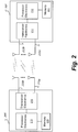
- FIG. 2 shows an example of a wireless network with two wireless communication devices.
- Wireless communication devices 205, 207 such as an access point (AP), base station (BS), wireless headset, access terminal (AT), client station, or mobile station (MS) can include circuitry such as processor electronics 210, 212.
- Processor electronics 210, 212 can include one or more processors that implement one or more techniques presented in this disclosure.
- Wireless communication devices 205, 207 include circuitry such as transceiver electronics 215, 217 to send and receive wireless signals over one or more antennas 220a, 220b, 222a, 222b.
- transceiver electronics 215, 217 include integrated transmitting and receiving circuitry.
- transceiver electronics 215, 217 include multiple radio units.
- a radio unit includes a baseband unit (BBU) and a radio frequency unit (RFU) to transmit and receive signals.
- Transceiver electronics 215, 217 can include one or more of: detector, decoder, modulator, and encoder. Transceiver electronics 215, 217 can include one or more analog circuits.
- Wireless communication devices 205, 207 include one or more memories 225, 227 configured to store information such as data, instructions, or both.
- wireless communication devices 205, 207 include dedicated circuitry for transmitting and dedicated circuitry for receiving.
- a wireless communication device 205, 207 is operable to act as a serving device (e.g., an access point), or a client device.
- a first wireless communication device 205 can transmit data to one or more devices via two or more spatial wireless communication channels such as orthogonal spatial subspaces, e.g., orthogonal Space Division Multiple Access (SDMA) subspaces.
- the first wireless communication device 205 can concurrently transmit data to a second wireless communication device 207 using a spatial wireless channel and can transmit data to a third wireless communication device (not shown) using a different spatial wireless channel.
- the first wireless communication device 205 implements a space division technique to transmit data to two or more wireless communication devices using two or more spatial multiplexing matrices to provide spatially separated wireless channels in a single frequency band.
- Wireless communication devices such as a MIMO enabled access point
- a MIMO enabled access point can participate in sounding to obtain channel state information for each of the client wireless communication devices.
- the access point can compute spatial multiplexing matrices, such as spatial steering matrices, based on the different channel state information to spatially separate signals to different client devices.
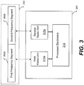
- FIG. 3 shows an example of a multi-radio wireless communication device and a layout of a composite signal that is produced by separate radio units of the device.
- a multi-radio wireless communication device 305 includes processor electronics 310 in communication with two or more radio units 315a, 315b.
- Processor electronics 310 can include one or more processors. In some implementations, processor electronics 310 include specialized logic to perform one or more specific functions.
- the processor electronics 310 can operate the radio units 315a-b to transmit and receive communication signals.
- the radio units 315a-b can generate different portions of a composite signal 350 that includes a first frequency segment 360a and a second frequency segment 360b.
- the first radio unit 315a generates an output signal based on the first frequency segment 360a
- the second radio unit 315b generates an output signal based on the second frequency segment 360b
- the device 305 includes circuitry to produce the composite signal based on a summation of the output signal of the first radio unit 315a and the output signal of the second radio unit 315b, and distributes the composite signal to one or more antenna interfaces.
- the radio units 315a-b can concurrently receive different physical layer frames of a data packet.
- the first radio unit 315a can receive communication signals that include one or more signals indicative of a first physical layer frame of a data packet.
- the first radio unit 315a can produce a first output based on the first physical layer frame.
- the second radio unit 315b can receive communication signals that include one or more signals indicative of a second physical layer frame of the data packet.
- the second radio unit 315b can produce a second output based on the second physical layer frame.
- Processor electronics 310 can combine information based on the first and second outputs of the radio units 315a-b to resolve the data packet.
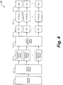
- FIG. 4 shows an example of a functional block diagram of a transmit path of wireless communication device.
- a transmit path 401 of a wireless communication device is configured for MIMO communications.
- a wireless communication device can include multiple transmit paths.
- a transmit path 401 can include an encoding module 405 configured to receive a data steam, such as an audio data stream, a video data stream, or combination thereof.
- the encoding module 405 outputs encoded bit streams to a spatial parsing module 410, which performs spatial mapping to produce multiple outputs.
- Outputs of the spatial parsing module 410 are input into constellation mapping modules 415, respectively.
- a constellation mapping module 415 includes a serial-to-parallel converter that converts an incoming serial stream to multiple parallel streams.
- the constellation mapping module 415 can perform quadrature amplitude modulation (QAM) on multiple streams produced by a serial-to-parallel conversion.
- the constellation mapping module 415 can output OFDM tones that are input to a spatial multiplexing matrix module 420.
- the spatial multiplexing matrix module 420 can multiply the OFDM tones by a spatial multiplexing matrix to produce signal data for multiple transmit antennas.
- Outputs of the spatial multiplexing matrix module 420 are input to IFFT modules 425.
- Outputs of the IFFT modules 425 are input to cyclic prefix (CP) modules 430.
- Outputs of the CP modules 430 are input to digital-to-analog converters (DACs) 435, which produce analog signals for transmission on multiple transmit antennas, respectively.
- DACs digital-to-analog converters
- FIG. 5 shows an example of an architecture that combines multiple transmission signals from separate radio units for transmission on multiple antennas.
- a device 500 can include two or more radio units with respective two or more radio pathways such as transmit paths 501a, 501b that are each configured for MIMO communications.
- a first transmit path 501a generates multiple transmit signals 510a, 510b, 510n for transmission on multiple transmit antennas 520a, 520b, 520n, respectively.
- a second transmit path 501b generates multiple transmit signals 511a, 511b, 511n for transmission on multiple transmit antennas 520a-n, respectively.
- the device 500 can include multiple summers 515a, 515b, 515n that are associated with multiple transmit antennas 520a-n respectively.
- summers 515a-n sum corresponding outputs of DACs in each of the transmit paths 501a-b to produce combined transmit signals for each of the antennas 520a-n.
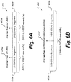
- FIG. 6A shows a layout of an example of a 160MHz composite signal having contiguous frequency segments with separate CSD phase shifts and separate carrier frequencies.
- the composite signal 600 includes two frequency segments 610a, 610b.
- the segments 610a-b include a LSB 80MHz segment 610a and a USB 80MHz segment 610b.
- the LSB 80MHz segment 610a is produced based on a carrier frequency 620a for the LSB.
- the USB 80MHz segment 610b is produced based on a carrier frequency 620b for the USB.
- Radio units of a device can generate the frequency segments 610a-b, respectively, using 80MHz CSD phase shifts.
- FIG. 6B shows a layout of an example of a 160MHz composite signal having contiguous frequency segments and a shared carried frequency.
- the composite signal 650 includes two contiguous frequency segments 655a, 655b that share a single carrier frequency 660.
- the segments 610a-b include a LSB 80MHz segment 655a and a USB 80MHz segment 655b.
- both types of devices should know how to apply and remove CSD phase shifts the same way.
- FIG. 7 shows an example of a technique to generate CSD phase shifts for a composite signal that is interoperable with a non-composite signal.
- a multi-radio device configured to implement the technique of FIG. 7 can use contiguous 160MHz CSD phase shift values to produce, via two radio units, signals corresponding to the LSB 80MHz segment 715a and the USB 80MHz segment 715b.
- the device can produce a composite signal 700 that includes the frequency segments 715a, 715b.
- the technique includes generating 160MHz CSD phase shifts for the LSB segment 715a based on 80MHz CSD phase shifts and a LSB phase shift value.
- the technique includes generating 160MHz CSD phase shifts for the USB segment 715b based on 80MHz CSD phase shifts and a USB phase shift value.
- the 160MHz LSB CSD phase shifts and the 160MHz USB CSD phase shifts are equivalent to CSD phase shifts that correspond to a 160MHz contiguous non-composite signal having a single frequency segment.
- the N seg value for the above-given expression for r RF ( t ) is set to one, despite there being two radio units and two segments.
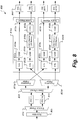
- FIG. 8 shows an example of a multi-radio device architecture with memories for CSD offset values.
- a device 800 includes a scrambler 805, encoder parser 810, forward error correction (FEC) modules 815, stream parser 820, frequency parsers 825a, 825b, radio pathways 830a, 830b, IFFT modules 860.
- the device 800 outputs a composite signal that is based on a LSB frequency segment and a USB frequency segment that are generated, respectively via separate radio pathways 830a-b.
- the radio pathways 830a-b include interleavers (Intlv) 832a-d, QAM modules 834a-d, memories 840a-b, CSD modules 850a-b, and spatial mappers 855a-b.
- the memory 840a is configured to store a CSD offset value for the LSB.
- the CSD module 850a which is communicatively coupled with the memory 840a, uses the CSD offset value for the LSB to apply cyclic shift delays to a modulated signal produced by a QAM module 834b.
- the memory 840b is configured to store a CSD offset value for the USB.
- the CSD module 850b which is communicatively coupled with the memory 840b, uses the CSD offset value for the USB to apply cyclic shift delays to a modulated signal produced by a QAM module 834d.
- the outputs of the radio pathways 830a-b can be transformed via IFFT modules 860 to produce signals in the time domain for over-the-air transmissions.
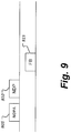
- FIG. 9 shows an example of an announcement frame that includes a CSD indicator.
- a first device can send a NDP announcement (NDPA) 905 frame that includes a non-contiguous flag.
- a non-contiguous flag can be an indicator that provides information regarding an application of CSD phase shifts to a composite signal.
- the non-contiguous flag can be set to one to indicate a transmission of a 160MHz contiguous composite signal from two radio units.
- a second device Based on receiving such an indication, a second device knows that 80MHz CSD phase shift values were applied on two 80MHz segments, respectively, in a subsequently received composite signal such as the NDP 910 or other packets.
- the second device sends a feedback (FB) 915 frame to the first device based on sounding measurements taken from the received version of the NDP 910.
- FB feedback
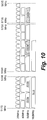
- FIG. 10 shows an example of frequency arrangements for WLAN communications.
- Some wireless standards partition unlicensed radio spectrum into channels.
- the channels can be 20MHz channels, 40MHz channels, 80MHz channels, 160MHz channels, or a combination thereof.
- the multi-radio device 800 of FIG. 8 can be configured for either contiguous frequency transmissions or non-contiguous frequency transmissions.
- the device 800 can generate a 160MHz composite signal via two radio units that are configured to use two non-adjacent 80MHz channels 1005a, 1005b.
- the device 800 can generate a 160MHz composite signal via two radio units that are configured to use two adjacent 80MHz channels 1015a, 1015b.
- a 160MHz channel 1010 occupies the same space as the two adjacent 80MHz channels 1015a, 1015b.
- a single radio device uses a single radio pathway to produce a 160MHz non-composite signal via one radio unit that is configured to use the 160MHz channel 1010.
- data processing apparatus encompasses all apparatus, devices, and machines for processing data, including by way of example a programmable processor, a computer, or multiple processors or computers.
- the apparatus can include, in addition to hardware, code that creates an execution environment for the computer program in question, e.g., code that constitutes processor firmware, a protocol stack, a database management system, an operating system, or a combination of one or more of them.
- a program (also known as a computer program, software, software application, script, or code) can be written in any form of programming language, including compiled or interpreted languages, or declarative or procedural languages, and it can be deployed in any form, including as a stand alone program or as a module, component, subroutine, or other unit suitable for use in a computing environment.
- a program does not necessarily correspond to a file in a file system.
- a program can be stored in a portion of a file that holds other programs or data (e.g., one or more scripts stored in a markup language document), in a single file dedicated to the program in question, or in multiple coordinated files (e.g., files that store one or more modules, sub programs, or portions of code).
- a program can be deployed to be executed on one computer or on multiple computers that are located at one site or distributed across multiple sites and interconnected by a communication network.
Landscapes
- Engineering & Computer Science (AREA)
- Signal Processing (AREA)
- Computer Networks & Wireless Communication (AREA)
- Physics & Mathematics (AREA)
- Discrete Mathematics (AREA)
- General Physics & Mathematics (AREA)
- Mathematical Physics (AREA)
- Mobile Radio Communication Systems (AREA)
- Radio Transmission System (AREA)
Applications Claiming Priority (2)
| Application Number | Priority Date | Filing Date | Title |
|---|---|---|---|
| US201161430428P | 2011-01-06 | 2011-01-06 | |
| PCT/US2011/066964 WO2012094174A1 (en) | 2011-01-06 | 2011-12-22 | Cyclic shift delay techniques for wlan multi-radio devices |
Publications (2)
| Publication Number | Publication Date |
|---|---|
| EP2661850A1 EP2661850A1 (en) | 2013-11-13 |
| EP2661850B1 true EP2661850B1 (en) | 2018-10-03 |
Family
ID=45529202
Family Applications (1)
| Application Number | Title | Priority Date | Filing Date |
|---|---|---|---|
| EP11811616.9A Active EP2661850B1 (en) | 2011-01-06 | 2011-12-22 | Cyclic shift delay techniques for wlan multi-radio devices |
Country Status (6)
| Country | Link |
|---|---|
| US (2) | US8625561B2 (enExample) |
| EP (1) | EP2661850B1 (enExample) |
| JP (1) | JP5901077B2 (enExample) |
| KR (1) | KR102046586B1 (enExample) |
| CN (1) | CN103430503B (enExample) |
| WO (1) | WO2012094174A1 (enExample) |
Families Citing this family (12)
| Publication number | Priority date | Publication date | Assignee | Title |
|---|---|---|---|---|
| US10411846B1 (en) * | 2009-03-24 | 2019-09-10 | Marvell International Ltd. | Multi-radio device for WLAN |
| US10504360B2 (en) | 2011-04-08 | 2019-12-10 | Ross Gilson | Remote control interference avoidance |
| US9281924B2 (en) * | 2011-04-13 | 2016-03-08 | Qualcomm Incorporated | Method and apparatus for generating various transmission modes for WLAN systems |
| US8971429B2 (en) | 2012-09-21 | 2015-03-03 | Qualcomm Incorporated | Cyclic shift delay detection using autocorrelations |
| US9497641B2 (en) | 2012-09-21 | 2016-11-15 | Qualcomm Incorporated | Cyclic shift delay detection using a classifier |
| US9726748B2 (en) * | 2012-09-21 | 2017-08-08 | Qualcomm Incorporated | Cyclic shift delay detection using signaling |
| US8971428B2 (en) | 2012-09-21 | 2015-03-03 | Qualcomm Incorporated | Cyclic shift delay detection using a channel impulse response |
| US10153812B2 (en) | 2015-02-10 | 2018-12-11 | Qualcomm Incorporated | Techniques for supporting multiple bandwidth modes |
| US10056949B2 (en) | 2015-02-10 | 2018-08-21 | Qualcomm Incorporated | Techniques for supporting multiple bandwidth modes |
| US20160255645A1 (en) * | 2015-02-27 | 2016-09-01 | Intel IP Corporation | Cyclic shift diversity in wireless communications |
| CN113067664B (zh) * | 2019-12-16 | 2022-06-14 | 华为技术有限公司 | 一种数据接收方法,数据发送方法以及相关设备 |
| US12438623B2 (en) * | 2022-12-21 | 2025-10-07 | Qualcomm Incorporated | Frequency dependent residual side band training signals |
Family Cites Families (29)
| Publication number | Priority date | Publication date | Assignee | Title |
|---|---|---|---|---|
| JP3808660B2 (ja) | 1999-03-31 | 2006-08-16 | 株式会社東芝 | 通信システム及び端末装置 |
| JP2001053716A (ja) * | 1999-08-17 | 2001-02-23 | Nec Corp | 無線伝送システム、無線伝送方法、送信装置及び受信装置 |
| JP3838237B2 (ja) | 2003-04-30 | 2006-10-25 | ソニー株式会社 | 無線通信システム、送信装置および受信装置 |
| CA2513345C (en) | 2003-06-18 | 2010-08-10 | Nippon Telegraph And Telephone Corporation | Wireless packet communication method and wireless packet communication apparatus |
| KR20050000709A (ko) * | 2003-06-24 | 2005-01-06 | 삼성전자주식회사 | 다중 접속 방식을 사용하는 통신 시스템의 데이터 송수신장치 및 방법 |
| US7738356B2 (en) * | 2005-06-28 | 2010-06-15 | Broadcom Corporation | Multiple stream cyclic-shifted delay transmitter |
| US20070153754A1 (en) | 2005-12-29 | 2007-07-05 | Nir Shapira | Method, apparatus and system of spatial division multiple access communication in a wireless local area network |
| KR100782844B1 (ko) | 2006-01-12 | 2007-12-06 | 삼성전자주식회사 | 무선랜에서 채널 본딩을 이용하여 데이터 프레임을전송하는 방법 및 장치 |
| CN101606339B (zh) * | 2006-01-13 | 2013-10-16 | Lg电子株式会社 | 使用基于反馈信息的天线选择实现发射分集和空间复用的方法和装置 |
| US7804800B2 (en) | 2006-03-31 | 2010-09-28 | Intel Corporation | Efficient training schemes for MIMO based wireless networks |
| JP5106129B2 (ja) * | 2007-01-10 | 2012-12-26 | パナソニック株式会社 | 基地局装置 |
| WO2008155764A2 (en) * | 2007-06-18 | 2008-12-24 | Duolink Ltd. | Wireless network architecture and method for base station utilization |
| CN101527700B (zh) * | 2008-03-05 | 2012-04-25 | 华为技术有限公司 | 正交频分多址系统中反向接入信道rach信号的接收方法及装置 |
| US8660144B2 (en) | 2008-03-11 | 2014-02-25 | Intel Corporation | Multi-receiver frame aggregation |
| US20100290449A1 (en) * | 2008-08-20 | 2010-11-18 | Qualcomm Incorporated | Preamble extensions |
| KR101766489B1 (ko) * | 2008-09-22 | 2017-08-08 | 선 페이턴트 트러스트 | 통신 장치 및 통신 방법 |
| US8295258B2 (en) * | 2009-02-17 | 2012-10-23 | Wavion, Ltd | Enhancing WLAN performance in the presence of interference |
| CN102369674B (zh) | 2009-03-31 | 2014-07-23 | 马维尔国际贸易有限公司 | 用于无线通信的方法、装置及系统 |
| WO2010118383A1 (en) | 2009-04-10 | 2010-10-14 | Marvell World Trade Ltd. | Signaling for multi-dimension wireless resource allocation |
| JP5649011B2 (ja) | 2009-04-13 | 2015-01-07 | マーベル ワールド トレード リミテッド | Wlan用の物理層フレーム形式 |
| US9485783B2 (en) | 2009-05-07 | 2016-11-01 | Qualcomm Incorporated | Enhanced multichannel access for very high throughput |
| US8379757B1 (en) | 2009-05-29 | 2013-02-19 | Marvell International Ltd. | Narrow-band OFDM mode for WLAN |
| CN102498687B (zh) | 2009-08-12 | 2015-09-09 | 马维尔国际贸易有限公司 | 用于无线通信的方法、装置及系统 |
| US20110069775A1 (en) * | 2009-09-21 | 2011-03-24 | Ralink Technology Corporation | Signal processing method and apparatus for mimo system |
| KR20110036485A (ko) | 2009-10-01 | 2011-04-07 | 엘지전자 주식회사 | 무선랜 시스템에서의 데이터 전송방법 및 장치 |
| US7920599B1 (en) * | 2010-02-03 | 2011-04-05 | Anna University | Methods and systems for synchronizing wireless transmission of data packets |
| US8619655B2 (en) * | 2010-06-09 | 2013-12-31 | Broadcom Corporation | Cyclic shift delay (CSD) short training field (STF) for orthogonal frequency division multiplexing (OFDM) signaling within multiple user, multiple access, and/or MIMO wireless communicaitons |
| US8619676B2 (en) | 2010-06-09 | 2013-12-31 | Broadcom Corporation | Legacy cyclic shift delay (CSD) for orthogonal frequency division multiplexing (OFDM) signaling within multiple user, multiple access, and/or MIMO wireless communications |
| US8934572B2 (en) * | 2010-08-31 | 2015-01-13 | Broadcom Corporation | Phase rotation for preambles within multiple user, multiple access, and/or MIMO wireless communications |
-
2011
- 2011-12-22 EP EP11811616.9A patent/EP2661850B1/en active Active
- 2011-12-22 KR KR1020137020145A patent/KR102046586B1/ko not_active Expired - Fee Related
- 2011-12-22 CN CN201180064422.XA patent/CN103430503B/zh active Active
- 2011-12-22 JP JP2013548430A patent/JP5901077B2/ja not_active Expired - Fee Related
- 2011-12-22 WO PCT/US2011/066964 patent/WO2012094174A1/en not_active Ceased
- 2011-12-22 US US13/335,789 patent/US8625561B2/en active Active
-
2014
- 2014-01-03 US US14/147,363 patent/US9397802B2/en active Active
Non-Patent Citations (1)
| Title |
|---|
| None * |
Also Published As
| Publication number | Publication date |
|---|---|
| US9397802B2 (en) | 2016-07-19 |
| EP2661850A1 (en) | 2013-11-13 |
| KR102046586B1 (ko) | 2019-11-19 |
| KR20140018224A (ko) | 2014-02-12 |
| US20140119464A1 (en) | 2014-05-01 |
| US8625561B2 (en) | 2014-01-07 |
| CN103430503A (zh) | 2013-12-04 |
| WO2012094174A1 (en) | 2012-07-12 |
| JP5901077B2 (ja) | 2016-04-06 |
| CN103430503B (zh) | 2016-06-22 |
| JP2014507845A (ja) | 2014-03-27 |
| US20120177019A1 (en) | 2012-07-12 |
Similar Documents
| Publication | Publication Date | Title |
|---|---|---|
| EP2661850B1 (en) | Cyclic shift delay techniques for wlan multi-radio devices | |
| US12170587B2 (en) | Transmitting apparatus | |
| US10419143B1 (en) | Multi-radio device for WLAN | |
| US7616704B2 (en) | Broadband multicarrier transmitter with subchannel frequency diversity for transmitting a plurality of spatial streams | |
| US8917795B1 (en) | Narrow-band OFDM mode for WLAN | |
| WO2021022736A1 (en) | Apparatus and method for enhanced physical downlink control channel transmission and reception | |
| JP7167087B2 (ja) | 送信装置および送信方法 | |
| CN109561507A (zh) | 选择用于传送数据分组的频带 | |
| JP7136975B2 (ja) | 送信方法、受信方法、送信装置、及び受信装置 | |
| US12207184B2 (en) | Terminal apparatus and communication method | |
| US9226270B1 (en) | Multi-radio device for WLAN | |
| CN108292965B (zh) | 发送方法、接收方法、发送装置及接收装置 | |
| US11265119B1 (en) | Multi-radio device for WLAN | |
| US20220124537A1 (en) | Method and apparatus for csi reporting based on a port selection codebook | |
| CN116438766A (zh) | 一种传输信号的方法及装置 | |
| CN118282428A (zh) | 移动通信基站系统和方法 | |
| WO2016203723A1 (ja) | 送信方法、受信方法、送信装置、及び受信装置 |
Legal Events
| Date | Code | Title | Description |
|---|---|---|---|
| PUAI | Public reference made under article 153(3) epc to a published international application that has entered the european phase |
Free format text: ORIGINAL CODE: 0009012 |
|
| 17P | Request for examination filed |
Effective date: 20130703 |
|
| AK | Designated contracting states |
Kind code of ref document: A1 Designated state(s): AL AT BE BG CH CY CZ DE DK EE ES FI FR GB GR HR HU IE IS IT LI LT LU LV MC MK MT NL NO PL PT RO RS SE SI SK SM TR |
|
| DAX | Request for extension of the european patent (deleted) | ||
| RIC1 | Information provided on ipc code assigned before grant |
Ipc: H04L 27/26 20060101AFI20180305BHEP Ipc: H04B 7/0417 20170101ALI20180305BHEP Ipc: H04L 5/00 20060101ALI20180305BHEP Ipc: H04B 7/06 20060101ALI20180305BHEP Ipc: H04L 27/18 20060101ALI20180305BHEP Ipc: H04B 7/02 20060101ALI20180305BHEP Ipc: H04B 7/12 20060101ALI20180305BHEP |
|
| GRAP | Despatch of communication of intention to grant a patent |
Free format text: ORIGINAL CODE: EPIDOSNIGR1 |
|
| RIN1 | Information on inventor provided before grant (corrected) |
Inventor name: ZHANG, HONGYUAN |
|
| INTG | Intention to grant announced |
Effective date: 20180424 |
|
| GRAS | Grant fee paid |
Free format text: ORIGINAL CODE: EPIDOSNIGR3 |
|
| GRAA | (expected) grant |
Free format text: ORIGINAL CODE: 0009210 |
|
| AK | Designated contracting states |
Kind code of ref document: B1 Designated state(s): AL AT BE BG CH CY CZ DE DK EE ES FI FR GB GR HR HU IE IS IT LI LT LU LV MC MK MT NL NO PL PT RO RS SE SI SK SM TR |
|
| REG | Reference to a national code |
Ref country code: GB Ref legal event code: FG4D |
|
| REG | Reference to a national code |
Ref country code: CH Ref legal event code: EP Ref country code: AT Ref legal event code: REF Ref document number: 1049865 Country of ref document: AT Kind code of ref document: T Effective date: 20181015 |
|
| REG | Reference to a national code |
Ref country code: IE Ref legal event code: FG4D Ref country code: DE Ref legal event code: R096 Ref document number: 602011052611 Country of ref document: DE |
|
| REG | Reference to a national code |
Ref country code: NL Ref legal event code: MP Effective date: 20181003 |
|
| REG | Reference to a national code |
Ref country code: LT Ref legal event code: MG4D |
|
| REG | Reference to a national code |
Ref country code: AT Ref legal event code: MK05 Ref document number: 1049865 Country of ref document: AT Kind code of ref document: T Effective date: 20181003 |
|
| PG25 | Lapsed in a contracting state [announced via postgrant information from national office to epo] |
Ref country code: NL Free format text: LAPSE BECAUSE OF FAILURE TO SUBMIT A TRANSLATION OF THE DESCRIPTION OR TO PAY THE FEE WITHIN THE PRESCRIBED TIME-LIMIT Effective date: 20181003 |
|
| PG25 | Lapsed in a contracting state [announced via postgrant information from national office to epo] |
Ref country code: CZ Free format text: LAPSE BECAUSE OF FAILURE TO SUBMIT A TRANSLATION OF THE DESCRIPTION OR TO PAY THE FEE WITHIN THE PRESCRIBED TIME-LIMIT Effective date: 20181003 Ref country code: IS Free format text: LAPSE BECAUSE OF FAILURE TO SUBMIT A TRANSLATION OF THE DESCRIPTION OR TO PAY THE FEE WITHIN THE PRESCRIBED TIME-LIMIT Effective date: 20190203 Ref country code: ES Free format text: LAPSE BECAUSE OF FAILURE TO SUBMIT A TRANSLATION OF THE DESCRIPTION OR TO PAY THE FEE WITHIN THE PRESCRIBED TIME-LIMIT Effective date: 20181003 Ref country code: BG Free format text: LAPSE BECAUSE OF FAILURE TO SUBMIT A TRANSLATION OF THE DESCRIPTION OR TO PAY THE FEE WITHIN THE PRESCRIBED TIME-LIMIT Effective date: 20190103 Ref country code: NO Free format text: LAPSE BECAUSE OF FAILURE TO SUBMIT A TRANSLATION OF THE DESCRIPTION OR TO PAY THE FEE WITHIN THE PRESCRIBED TIME-LIMIT Effective date: 20190103 Ref country code: PL Free format text: LAPSE BECAUSE OF FAILURE TO SUBMIT A TRANSLATION OF THE DESCRIPTION OR TO PAY THE FEE WITHIN THE PRESCRIBED TIME-LIMIT Effective date: 20181003 Ref country code: LT Free format text: LAPSE BECAUSE OF FAILURE TO SUBMIT A TRANSLATION OF THE DESCRIPTION OR TO PAY THE FEE WITHIN THE PRESCRIBED TIME-LIMIT Effective date: 20181003 Ref country code: HR Free format text: LAPSE BECAUSE OF FAILURE TO SUBMIT A TRANSLATION OF THE DESCRIPTION OR TO PAY THE FEE WITHIN THE PRESCRIBED TIME-LIMIT Effective date: 20181003 Ref country code: LV Free format text: LAPSE BECAUSE OF FAILURE TO SUBMIT A TRANSLATION OF THE DESCRIPTION OR TO PAY THE FEE WITHIN THE PRESCRIBED TIME-LIMIT Effective date: 20181003 Ref country code: FI Free format text: LAPSE BECAUSE OF FAILURE TO SUBMIT A TRANSLATION OF THE DESCRIPTION OR TO PAY THE FEE WITHIN THE PRESCRIBED TIME-LIMIT Effective date: 20181003 Ref country code: AT Free format text: LAPSE BECAUSE OF FAILURE TO SUBMIT A TRANSLATION OF THE DESCRIPTION OR TO PAY THE FEE WITHIN THE PRESCRIBED TIME-LIMIT Effective date: 20181003 |
|
| PG25 | Lapsed in a contracting state [announced via postgrant information from national office to epo] |
Ref country code: AL Free format text: LAPSE BECAUSE OF FAILURE TO SUBMIT A TRANSLATION OF THE DESCRIPTION OR TO PAY THE FEE WITHIN THE PRESCRIBED TIME-LIMIT Effective date: 20181003 Ref country code: SE Free format text: LAPSE BECAUSE OF FAILURE TO SUBMIT A TRANSLATION OF THE DESCRIPTION OR TO PAY THE FEE WITHIN THE PRESCRIBED TIME-LIMIT Effective date: 20181003 Ref country code: RS Free format text: LAPSE BECAUSE OF FAILURE TO SUBMIT A TRANSLATION OF THE DESCRIPTION OR TO PAY THE FEE WITHIN THE PRESCRIBED TIME-LIMIT Effective date: 20181003 Ref country code: GR Free format text: LAPSE BECAUSE OF FAILURE TO SUBMIT A TRANSLATION OF THE DESCRIPTION OR TO PAY THE FEE WITHIN THE PRESCRIBED TIME-LIMIT Effective date: 20190104 Ref country code: PT Free format text: LAPSE BECAUSE OF FAILURE TO SUBMIT A TRANSLATION OF THE DESCRIPTION OR TO PAY THE FEE WITHIN THE PRESCRIBED TIME-LIMIT Effective date: 20190203 |
|
| REG | Reference to a national code |
Ref country code: DE Ref legal event code: R097 Ref document number: 602011052611 Country of ref document: DE |
|
| PG25 | Lapsed in a contracting state [announced via postgrant information from national office to epo] |
Ref country code: IT Free format text: LAPSE BECAUSE OF FAILURE TO SUBMIT A TRANSLATION OF THE DESCRIPTION OR TO PAY THE FEE WITHIN THE PRESCRIBED TIME-LIMIT Effective date: 20181003 Ref country code: DK Free format text: LAPSE BECAUSE OF FAILURE TO SUBMIT A TRANSLATION OF THE DESCRIPTION OR TO PAY THE FEE WITHIN THE PRESCRIBED TIME-LIMIT Effective date: 20181003 |
|
| REG | Reference to a national code |
Ref country code: CH Ref legal event code: PL |
|
| PLBE | No opposition filed within time limit |
Free format text: ORIGINAL CODE: 0009261 |
|
| STAA | Information on the status of an ep patent application or granted ep patent |
Free format text: STATUS: NO OPPOSITION FILED WITHIN TIME LIMIT |
|
| PG25 | Lapsed in a contracting state [announced via postgrant information from national office to epo] |
Ref country code: SM Free format text: LAPSE BECAUSE OF FAILURE TO SUBMIT A TRANSLATION OF THE DESCRIPTION OR TO PAY THE FEE WITHIN THE PRESCRIBED TIME-LIMIT Effective date: 20181003 Ref country code: SK Free format text: LAPSE BECAUSE OF FAILURE TO SUBMIT A TRANSLATION OF THE DESCRIPTION OR TO PAY THE FEE WITHIN THE PRESCRIBED TIME-LIMIT Effective date: 20181003 Ref country code: RO Free format text: LAPSE BECAUSE OF FAILURE TO SUBMIT A TRANSLATION OF THE DESCRIPTION OR TO PAY THE FEE WITHIN THE PRESCRIBED TIME-LIMIT Effective date: 20181003 Ref country code: LU Free format text: LAPSE BECAUSE OF NON-PAYMENT OF DUE FEES Effective date: 20181222 Ref country code: MC Free format text: LAPSE BECAUSE OF FAILURE TO SUBMIT A TRANSLATION OF THE DESCRIPTION OR TO PAY THE FEE WITHIN THE PRESCRIBED TIME-LIMIT Effective date: 20181003 Ref country code: EE Free format text: LAPSE BECAUSE OF FAILURE TO SUBMIT A TRANSLATION OF THE DESCRIPTION OR TO PAY THE FEE WITHIN THE PRESCRIBED TIME-LIMIT Effective date: 20181003 |
|
| 26N | No opposition filed |
Effective date: 20190704 |
|
| REG | Reference to a national code |
Ref country code: IE Ref legal event code: MM4A |
|
| REG | Reference to a national code |
Ref country code: BE Ref legal event code: MM Effective date: 20181231 |
|
| PG25 | Lapsed in a contracting state [announced via postgrant information from national office to epo] |
Ref country code: SI Free format text: LAPSE BECAUSE OF FAILURE TO SUBMIT A TRANSLATION OF THE DESCRIPTION OR TO PAY THE FEE WITHIN THE PRESCRIBED TIME-LIMIT Effective date: 20181003 Ref country code: IE Free format text: LAPSE BECAUSE OF NON-PAYMENT OF DUE FEES Effective date: 20181222 |
|
| PG25 | Lapsed in a contracting state [announced via postgrant information from national office to epo] |
Ref country code: BE Free format text: LAPSE BECAUSE OF NON-PAYMENT OF DUE FEES Effective date: 20181231 |
|
| PG25 | Lapsed in a contracting state [announced via postgrant information from national office to epo] |
Ref country code: LI Free format text: LAPSE BECAUSE OF NON-PAYMENT OF DUE FEES Effective date: 20181231 Ref country code: CH Free format text: LAPSE BECAUSE OF NON-PAYMENT OF DUE FEES Effective date: 20181231 |
|
| REG | Reference to a national code |
Ref country code: DE Ref legal event code: R081 Ref document number: 602011052611 Country of ref document: DE Owner name: MARVELL INTERNATIONAL LTD., BM Free format text: FORMER OWNER: MARVELL WORLD TRADE LTD., ST. MICHAEL, BB Ref country code: DE Ref legal event code: R081 Ref document number: 602011052611 Country of ref document: DE Owner name: NXP USA, INC., AUSTIN, US Free format text: FORMER OWNER: MARVELL WORLD TRADE LTD., ST. MICHAEL, BB Ref country code: DE Ref legal event code: R082 Ref document number: 602011052611 Country of ref document: DE Representative=s name: GRUENECKER PATENT- UND RECHTSANWAELTE PARTG MB, DE |
|
| PG25 | Lapsed in a contracting state [announced via postgrant information from national office to epo] |
Ref country code: MT Free format text: LAPSE BECAUSE OF NON-PAYMENT OF DUE FEES Effective date: 20181222 |
|
| REG | Reference to a national code |
Ref country code: GB Ref legal event code: 732E Free format text: REGISTERED BETWEEN 20200109 AND 20200115 |
|
| PGFP | Annual fee paid to national office [announced via postgrant information from national office to epo] |
Ref country code: FR Payment date: 20191224 Year of fee payment: 9 |
|
| PG25 | Lapsed in a contracting state [announced via postgrant information from national office to epo] |
Ref country code: TR Free format text: LAPSE BECAUSE OF FAILURE TO SUBMIT A TRANSLATION OF THE DESCRIPTION OR TO PAY THE FEE WITHIN THE PRESCRIBED TIME-LIMIT Effective date: 20181003 |
|
| PGFP | Annual fee paid to national office [announced via postgrant information from national office to epo] |
Ref country code: GB Payment date: 20191226 Year of fee payment: 9 |
|
| PG25 | Lapsed in a contracting state [announced via postgrant information from national office to epo] |
Ref country code: HU Free format text: LAPSE BECAUSE OF FAILURE TO SUBMIT A TRANSLATION OF THE DESCRIPTION OR TO PAY THE FEE WITHIN THE PRESCRIBED TIME-LIMIT; INVALID AB INITIO Effective date: 20111222 Ref country code: MK Free format text: LAPSE BECAUSE OF NON-PAYMENT OF DUE FEES Effective date: 20181003 Ref country code: CY Free format text: LAPSE BECAUSE OF FAILURE TO SUBMIT A TRANSLATION OF THE DESCRIPTION OR TO PAY THE FEE WITHIN THE PRESCRIBED TIME-LIMIT Effective date: 20181003 |
|
| REG | Reference to a national code |
Ref country code: DE Ref legal event code: R082 Ref document number: 602011052611 Country of ref document: DE Ref country code: DE Ref legal event code: R081 Ref document number: 602011052611 Country of ref document: DE Owner name: NXP USA, INC., AUSTIN, US Free format text: FORMER OWNER: MARVELL INTERNATIONAL LTD., HAMILTON, BM Ref country code: DE Ref legal event code: R082 Ref document number: 602011052611 Country of ref document: DE Representative=s name: GRUENECKER PATENT- UND RECHTSANWAELTE PARTG MB, DE |
|
| REG | Reference to a national code |
Ref country code: DE Ref legal event code: R082 Ref document number: 602011052611 Country of ref document: DE |
|
| REG | Reference to a national code |
Ref country code: DE Ref legal event code: R082 Ref document number: 602011052611 Country of ref document: DE |
|
| GBPC | Gb: european patent ceased through non-payment of renewal fee |
Effective date: 20201222 |
|
| PG25 | Lapsed in a contracting state [announced via postgrant information from national office to epo] |
Ref country code: FR Free format text: LAPSE BECAUSE OF NON-PAYMENT OF DUE FEES Effective date: 20201231 |
|
| PG25 | Lapsed in a contracting state [announced via postgrant information from national office to epo] |
Ref country code: GB Free format text: LAPSE BECAUSE OF NON-PAYMENT OF DUE FEES Effective date: 20201222 |
|
| P01 | Opt-out of the competence of the unified patent court (upc) registered |
Effective date: 20230725 |
|
| PGFP | Annual fee paid to national office [announced via postgrant information from national office to epo] |
Ref country code: DE Payment date: 20251126 Year of fee payment: 15 |