EP1635517B1 - Wireless packet communication method - Google Patents
Wireless packet communication method Download PDFInfo
- Publication number
- EP1635517B1 EP1635517B1 EP04746380.7A EP04746380A EP1635517B1 EP 1635517 B1 EP1635517 B1 EP 1635517B1 EP 04746380 A EP04746380 A EP 04746380A EP 1635517 B1 EP1635517 B1 EP 1635517B1
- Authority
- EP
- European Patent Office
- Prior art keywords
- data
- transmission
- frame
- data packets
- packet
- Prior art date
- Legal status (The legal status is an assumption and is not a legal conclusion. Google has not performed a legal analysis and makes no representation as to the accuracy of the status listed.)
- Active
Links
Images


Classifications
-
- H—ELECTRICITY
- H04—ELECTRIC COMMUNICATION TECHNIQUE
- H04W—WIRELESS COMMUNICATION NETWORKS
- H04W28/00—Network traffic management; Network resource management
- H04W28/02—Traffic management, e.g. flow control or congestion control
- H04W28/06—Optimizing the usage of the radio link, e.g. header compression, information sizing, discarding information
-
- H—ELECTRICITY
- H04—ELECTRIC COMMUNICATION TECHNIQUE
- H04B—TRANSMISSION
- H04B7/00—Radio transmission systems, i.e. using radiation field
- H04B7/02—Diversity systems; Multi-antenna system, i.e. transmission or reception using multiple antennas
-
- H—ELECTRICITY
- H04—ELECTRIC COMMUNICATION TECHNIQUE
- H04L—TRANSMISSION OF DIGITAL INFORMATION, e.g. TELEGRAPHIC COMMUNICATION
- H04L47/00—Traffic control in data switching networks
- H04L47/10—Flow control; Congestion control
- H04L47/36—Flow control; Congestion control by determining packet size, e.g. maximum transfer unit [MTU]
-
- H—ELECTRICITY
- H04—ELECTRIC COMMUNICATION TECHNIQUE
- H04W—WIRELESS COMMUNICATION NETWORKS
- H04W28/00—Network traffic management; Network resource management
- H04W28/02—Traffic management, e.g. flow control or congestion control
- H04W28/10—Flow control between communication endpoints
- H04W28/14—Flow control between communication endpoints using intermediate storage
-
- H—ELECTRICITY
- H04—ELECTRIC COMMUNICATION TECHNIQUE
- H04W—WIRELESS COMMUNICATION NETWORKS
- H04W28/00—Network traffic management; Network resource management
- H04W28/02—Traffic management, e.g. flow control or congestion control
- H04W28/04—Error control
-
- H—ELECTRICITY
- H04—ELECTRIC COMMUNICATION TECHNIQUE
- H04W—WIRELESS COMMUNICATION NETWORKS
- H04W74/00—Wireless channel access, e.g. scheduled or random access
Definitions
- the present invention relates to a wireless packet communication method for transmitting a plurality of data packets simultaneously between two wireless stations (hereinafter STAs) using a plurality of radio channels and Multiple Input Multiple Output (hereinafter MINO). More particularly, the present invention relates to a wireless packet communication method for generation of a plurality of data packets to be transmitted simultaneously.
- STAs wireless stations
- MINO Multiple Input Multiple Output
- a radio channel to be used is determined in advance. Prior to transmission of data packets, carrier sense is performed to detect whether or not that radio channel is idle. Only when that radio channel is idle, one data packet is transmitted. This management process enables a plurality of STAs to share one radio channel in a staggered manner (1) International Standard ISO/IEC 8802-11 ANSI/EEE Std.
- MIMO technique Kurosaki et al., "100Mbit/s SDM-COFDM over MIMO Channel for Broadband Mobile Communications", Technical Reports of the Institute of Electronics, Information and Communication Engineers, A . P 2001-96, RCS2001-135(2001-10 )
- MIMO technique different data packets are transmitted from a plurality of antennas on the same radio channel at the same time.
- the data packets transmitted at the same time on the same radio channel are received by digital signal processing that can deal with the difference in propagation coefficients of the respective data packets received by a plurality of wireless antennas in an opposed STA.
- a MIMO number is determined in accordance with the propagation coefficients and the like.
- each STA has a plurality of wireless network interfaces and can use a plurality of radio channels
- different radio channels can be used between a plurality of STAs.
- improvement of the throughput is promising, as compared with communication performed by time-dividing one radio channel.
- the case is considered where the center frequencies of radio channels #1 and #2 are close to each other and the transmission time is different between data packets that are transmitted simultaneously from the radio channels #1 and #2, as shown in Fig. 28 .
- the data packet transmitted from the radio channel #1 is shorter.
- the radio channel #1 may not receive the ACK packet because of leakage power from the radio channel #2. In this situation, the throughput cannot be improved even if transmission is carried out by using a plurality of radio channels at the same time.
- the data size of a data frame input from a network is not constant.
- the packet time length (transmission time) of each data packet also changes. Therefore, even when a plurality of data packets are transmitted at the same time, as shown in Fig. 28 , it is highly likely that a packet time length difference occurs between the data packets and causes a failure in the receiving of the ACK packet.
- a data frame input from a wired network e.g., Ethernet (registered trademark) frame
- a MAC Media Access Control
- one data frame is converted into one MAC frame from which one data packet is generated. Therefore, even if the data size of a data field in a data frame is small, that data frame is converted into one MAC frame and is transmitted as one data packet (wireless packet).
- the maximum size of the data field of a MAC frame in accordance with IEEE802.11 Standard is 2296 bytes
- the data size of the data field of an Ethernet (registered trademark) frame that is typically used as a data frame is limited to 1500 bytes. Therefore, even if the Ethernet (trademark) frame has the maximum size, that Ethernet frame has some leftover in the maximum size (2296 bytes) of the data field of the MAC frame. That is, the conventional system does not effectively use the maximum data size that can be transmitted in one MAC frame, and has a limitation in the improvement of the throughput.
- Fig. 29 shows an exemplary configuration of a wireless LAN system.
- a mobile terminal (address: S1) 11, a server (address: S2) 12, and a server (address: S3) 13 are connected through an access point (hereinafter AP) (address: AP) 10.
- the mobile terminal 11 and the AP 10 are connected to each other through a wireless line on which wireless packets are transmitted.
- the AP 10 and the servers 12 and 13 are connected through a router and the Internet. Ethernet (registered trademark) frames are transmitted between them.
- a transmission direction from the servers 12 and 13 to the mobile terminal 11 is called as a "downlink”
- a transmission direction from the mobile terminal 11 to the servers 12 and 13 is called as an "uplink".
- Fig. 30 shows a frame format for the downlink of the wireless LAN system.
- an Ethernet frame transmitted from the server 12 or 13 to the AP 10 contains a header, a frame body, and FCS.
- a destination address DA and a source address SA are set to "S1" and "S2", respectively.
- the frame body accommodates an IP packet for which the destination address DA and the source address SA are set to "S1" and "S2", respectively.
- the Ethernet frame transmitted from the server 12 or 13 is converted into a wireless packet in the AP 10 and is transmitted to the mobile terminal 11.
- the wireless packet contains a MAC header, a frame body, FCS, and the like.
- "S1" is set as a destination address DA in a PHY layer
- "AP” is set as BSS (Basic service set) ID corresponding to a source address in the PHY layer
- "S2" is set as a source address SA.
- the frame body accommodates an IP packet for which "S1" is set as the destination address DA and "S2" is set as the source address SA.
- Fig. 31 shows a frame format for the uplink of the wireless LAN system.
- the mobile terminal 1 1 generates an IP packet to the server 12 or 13.
- "S2" is set as a destination address DA
- "S1" is set as a source address SA.
- a wireless packet transmitted from the mobile terminal 1 1 to the AP 10 contains a MAC header, a frame body, FCS, and the like.
- BSSID corresponding to a destination address in the PHY layer is set to "AP”
- a source address SA in the PHY layer is set to "S1”
- a destination address DA is set to "S2”.
- the frame body accommodates the IP packet for which the destination address DA is set to "S2" and the source address SA is set to "S1".
- the wireless packet transmitted from the mobile terminal 1 1 is converted into an Ethernet frame in the AP 10 and is transmitted to the server 12 or 13.
- the Ethernet frame contains a header, a frame body, and FCS.
- a destination address DA and a source address SA are set to "S2" and "S1", respectively.
- the frame body accommodates the IP packet for which the destination address DA and the source address SA are set to "S2" and "S1", respectively.
- a conventional AP generates one wireless packet from one Ethernet frame to the mobile terminal and transmits that wireless packet on the downlink of the PHY layer from the AP to the mobile terminal. From a viewpoint of improving transmission efficiency, a method is considered to be effective that generates one or more wireless packets from a plurality of Ethernet frames transmitted from a plurality of servers to the same mobile terminal and then transmits those one or more wireless packets in one lump.
- a conventional mobile terminal generates one wireless packet from one IP packet to a server and transmits that wireless packet on the uplink of the PHY layer from the mobile terminal to the AP.
- a method is considered to be effective that generates one or more wireless packets from a plurality of IP packets to the same server and transmits those one or more wireless packets in one lump.
- another method can be considered, in which one or more wireless packets are generated from not only IP packets to the same servers but also IP packets that are transmitted to different servers through the same AP, and are transmitted in one lump.
- IP packets to the same server can be found by referring to their destination addresses DA. It is also possible to find whether or not a plurality of IP packets to different servers go through the same AP by checking their destination addresses DA against the AP address.
- JP H05 35624 A relates to data transmission between a computer and a peripheral device such a printer.
- a means for data communication control is part of the computer, divides data sent from the computer into prescribed byte lengths, and constitutes them to a packet to which management information such as the packet number, data length, and error correction code is added. Each packet thereof is allocated to a radio communication control part, and plural packets are transmitted in parallel. On the printer, the packet number is recognized from the management information of the packets received in parallel, and in accordance therewith, the data is reconstituted.
- US 2003/074669 A1 relates to on-demand data transmission.
- a plurality of section packet data are formed by performing packet data transmission/reception and dividing encoded data into a plurality of data segments.
- the plurality of section packet data are coded by performing a specific coding process on each of the plurality of data segments, and the plurality of section packet data arc reformed into the data segments by performing a specific decoding process.
- the plurality of section packet data are then stored in a data memory.
- Each of the plurality of section packet data is repeatedly retrieved from the data memory, and the resulting sequences of section packet data are then sequentially transmitted on the corresponding data transmission channels.
- AP access point
- the invention relates to the third, tenth and eleventh embodiments discussed below.
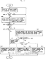
- Fig. 1 is a flowchart according to a first embodiment of the present invention.
- Fig. 2 shows an exemplary operation in the first embodiment of the present invention.
- a transmission-standby data frame in a transmission buffer in the following description is a data frame transmitted between two STAs.
- An idle radio channel is searched from all available radio channels by carrier sense (S001).
- the number of the detected idle channels is assumed to be N.
- N the number of the detected idle channels.
- it is searched whether or not there is a transmission-standby data frame in a transmission buffer (S002 and S003).
- S004 the procedure goes back to the carrier sense.
- N 1, one data block is generated from one data frame (S005 and S006).
- a header field containing control information such as destination information and an FCS (Frame Check Sequence) part containing an error checking code (hereinafter, referred to as "a header and the like") are added to the thus generated data block, thereby generating a data packet.
- the data packet is transmitted by using one radio channel (S007).
- a transmission rate of each radio channel may be fixed in advance, or may be set on a case-by-case basis by selecting one of a plurality of transmission rates determined in advance, for example, based on the quality of a wireless line.
- the transmission rates of the respective radio channels are checked (S008). At this time, the number X of data packets that are to be transmitted simultaneously is determined (X ⁇ N).
- X ⁇ N the number of data packets that are to be transmitted simultaneously.
- a data part of one data frame is fragmented into X so as to generate X data blocks having the same packet time length (S009).
- two radio channels are idle, for example, two data packets can be transmitted at the same time.
- the data part of one data frame is equally fragmented so as to generate two data blocks.
- the data part of one data frame is fragmented into X at a size ratio corresponding to the transmission rates, so as to generate X data blocks having the same packet time length (transmission time) (S010).
- S010 packet time length
- the data part of one data frame is fragmented at a packet size ratio of 1:2 so as to generate two data blocks, as shown in Fig. 2(2) .
- X data packets are generated by adding a header and the like to each of the X data blocks.
- the thus generated X data packets are transmitted simultaneously by using X radio channels (S011).
- the data packets transmitted simultaneously have the same packet time length, as shown in Fig. 2 . Therefore, transmission of the X data packets terminates at the same time.
- ACK packets after that transmission can be received without being affected by leakage power.
- a termination time of transmission of each data packet is different by a time corresponding to a difference of the packet time length.
- a time at which each ACK packet is received is different by the time corresponding to the difference of the packet time length.
- each ACK packet can be received without being affected by leakage power. In other words, it is not always necessary that the packet time lengths of the data packets to be transmitted simultaneously are strictly the same. The phrase "having the same packet time length" in the claims is written considering the above.
- Fig. 3 is a flowchart according to a second embodiment of the present invention.
- a smallest one of the transmission rates is selected as a common transmission rate (S012). In this case, it is not necessary to perform the process in Step S010 of the first embodiment.
- One data frame is fragmented into X in Step S009 so as to generate X data blocks having the same packet time length.
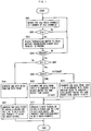
- Fig. 4 is a flowchart according to a third embodiment of the present invention.
- Fig. 5 shows an exemplary operation in the third embodiment of the present invention. It is assumed that radio channels #1 and #2 are provided between two STAs. A transmission stand-by data packet in a transmission buffer in the following description is a data packet to be transmitted between those two STAs.
- a feature of the present embodiment is to use MIMO in the first embodiment.
- An idle radio channel is searched from all available radio channels by carrier sense (S001).
- the number of the detected idle channels is assumed to be N.
- a total number of MIMOs is calculated as "a number of simultaneous transmissions" (S002 and S101).
- S002 and S101 For simplification, it is assumed that the MIMO numbers of the respective radio channels are the same and the number of simultaneous transmissions is a product (NL) of the number N of the idle channels and the MIMO number L.
- transmission rates of the respective radio channels are checked (S008).
- the number X (X ⁇ NL) of data packets to be transmitted simultaneously is also determined.
- a data part of one data frame is fragmented into X so as to generate X data blocks having the same packet time length (S104). For example, when two radio channels are idle and the MIMO number L of each radio channel is 2, four data packets can be transmitted at the same time. Therefore, the data part of one data frame is equally fragmented to generate four data blocks, as shown in Fig. 5(1) .
- transmission rates thereof are 6 Mbit/s and 12 Mbit/s, respectively, and the MIMO number L of each channel is 2
- the data part of one data frame is fragmented at a packet size ratio of 1:2
- each of the resultant data blocks is equally fragmented, thereby generating four data blocks, as shown in Fig. 5(2) .
- transmission rates of respective transmission media for MIMO are different, it is only necessary to perform fragmentation in accordance with the transmission rates in a similar manner.
- X data packets are generated by adding a header and the like to each of the X data blocks.
- the X data packets are transmitted simultaneously by using ceil (X/L) radio channels and MIMO (S107), where ceil (x) represents the smallest integer equal to or larger than x (i.e., an integer obtained by rounding up x).
- ceil (x) represents the smallest integer equal to or larger than x (i.e., an integer obtained by rounding up x).
- ceil (x) represents the smallest integer equal to or larger than x (i.e., an integer obtained by rounding up x).
- the simultaneous transmission of the data packets terminates at the same time, because those data packets have the same packet time length, as shown in Fig. 5 .
- ACK packets after that transmission can be received without being affected by leakage power.
- Fig. 6 is a flowchart according to a fourth embodiment of the present invention.
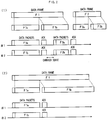
- Fig. 7 shows an exemplary operation in the fourth embodiment of the present invention.
- radio channels #1 and #2 are provided between two radio channels.
- a transmission stand-by data packet in a transmission buffer is a data packet transmitted between those two STAs.
- An idle radio channel is searched from all available radio channels by carrier sense (S001).
- the number of the detected idle channels is assumed to be N.
- it is then searched whether or not there is a transmission-standby data frame in the transmission buffer (S002 and S003).
- S002 and S003 When there is no transmission-standby data frame, the procedure goes back to carrier sense.
- the procedure goes ahead (S004).
- the maximum size Dmax that can be transmitted in one MAC packet is determined, and a total of the maximum data size Dmax • X in the case where simultaneous transmission is performed using X radio channels is calculated.
- data parts of transmission-standby data frames are connected so as not to exceed the above total of the maximum data size (S201).
- the connected data frames are divided into X so as to generate X data blocks having the same packet time length (S202).
- the maximum size in each radio channel Dmax • Ri/Rmax is determined, assuming that a transmission rate of each radio channel is Ri (i is an integer from 1 to X), the maximum transmission rate is Rmax, and the maximum size of data that can be transmitted in one MAC packet is Dmax.
- the total of the maximum data size when simultaneous transmission is performed using X radio channels is calculated.
- data parts of transmission-standby data frames are connected so as not to exceed the above total of the maximum data size (S203).
- the connected data frames are divided into X at a size ratio corresponding to the transmission rates Ri, thereby generating X data blocks having the same packet time length (transmission time) (S204).
- X data packets are generated by adding a header and the like to each data block.
- the X data packets are transmitted simultaneously using X radio channels (S205).
- the three data frames contain a data part F1 of 500 bytes, a data part F2 of 1500 bytes, and a data part F3 of 1000 bytes, respectively.
- a data block of 3000 bytes is generated by connecting those data parts. Then, the thus generated data block is divided at a packet size ratio of 1:2, thereby generating a data block of 1000 bytes and a data block of 2000 bytes.
- a size ratio of data parts of two data packets generated from those two data blocks is 1:2, and is the same as a ratio of the transmission rates of the corresponding radio channels.
- the data packets require the same length of time for transmission, i.e., have the same packet time length. Therefore, ACK packets after the transmission of those data packets can be received without being affected by leakage power.
- Fig. 8 is a flowchart according to a fifth embodiment of the present invention.
- a feature of the present invention is to use MIMO in the fourth embodiment.
- An idle radio channel is searched from all available channels by carrier sense (S001).
- the number of the detected idle channels is assumed to be N.
- a total number of MIMOs of the respective radio channels is calculated as "a number of simultaneous transmissions" (S002 and S101).
- S002 and S101 For simplification, the description is made assuming that the MIMO numbers of the respective radio channels are the same and the number of simultaneous transmissions is a product (NL) of the number N of idle channels and the MIMO number L.
- transmission rates of the respective radio channels are also checked (S008).
- the maximum size Dmax that can be transmitted in one MAC packet is determined, and a total of the maximum data size Dmax • X in the case where X data packets are transmitted simultaneously by using the radio channels and MIMO is calculated.
- data parts of transmission stand-by data frames are connected so as not to exceed the above total of the maximum data size (S211).
- the connected data frames are divided into X, thereby generating X data blocks having the same packet time length (S212).
- the maximum size Dmax • Ri/Rmax for each transmission medium is determined, where a transmission rate of each of transmission media formed by radio channels and MIMO is Ri (i is an integer from 1 to X), the maximum transmission rate is Rmax, and the maximum size that can be transmitted in one MAC packet is Dmax. Then, the total of the maximum data size in the case where X data packets are transmitted simultaneously by using radio channels and MIMO is calculated. Data parts of the transmission stand-by data frames are connected so as not to exceed the total of the maximum data size (S213). The connected data frames are divided into N N at a size ratio corresponding to the transmission rates Ri, thereby generating N N data blocks (S214).
- X data packets are generated by adding a header and the like to each data block.
- the X data packets are transmitted simultaneously by using ceil (X/L) radio channels and MIMO (S216).
- Fig. 9 is a flowchart according to a sixth embodiment of the present invention.
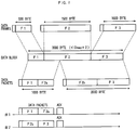
- Figs. 10 and 11 show exemplary operations in the sixth embodiment of the present invention.
- radio channels #1, #2, and #3 are provided between two STAs.
- a transmission stand-by data packet in a transmission buffer in the following description is a data packet transmitted between those two STAs. It is assumed that transmission rates of the respective radio channels are set to be the same.
- An idle radio channel is searched from all available radio channels by carrier sense (S001).
- the number of the detected idle channels is assumed to be N.
- it is then searched whether or not there is a transmission-standby data frame in the transmission buffer (S002 and S003).
- S002 and S003 When there is no transmission-standby data frame, the procedure goes back to carrier sense.
- the procedure goes ahead (S004).
- X (X ⁇ N) of data packets to be transmitted simultaneously is determined.
- N 1 by setting X to 1.
- X data blocks are generated by aggregating transmission-standby data frames in order (S301). Please note that the data frames are aggregated in such a manner that the data size of each data block does not exceed the maximum data size Dmax that can be transmitted in one MAC frame (e.g., 2296 bytes).
- Fig. 10 shows an example in which data frames 1 and 2 are assigned to the radio channel #1, data frames 3, 4, and 5 are assigned to the radio channel #2, and a data frame 6 is assigned to the radio channel #3. An assignment and management method for forming those data blocks will be described later.
- Step S303 for adding dummy data is omitted.
- X data packets are generated by adding a header and the like to each data block and are transmitted simultaneously by using X radio channels (S304).
- the data packets of the respective radio channels are transmitted at approximately the same time in a period from time t1 to time t2, and ACK packets can be received at approximately the same time in a period from time t3 to time t4, as shown in Fig. 10 .
- Fig. 11 shows a method for assigning and managing data frames.
- Fig. 11(1) shows a method in which data frames accumulated in the transmission buffer are assigned to the radio channels in order from the first one of the data frames until the total data size in each radio channel reaches the largest size that does not exceed the maximum data size Dmax, thereby generating data blocks.
- the data frames 1 and 2 are assigned to the radio channel #1
- the data frames 3, 4, and 5 are assigned to the radio channel #2
- the data frame 6 is assigned to the radio channel #3. Please note that given correspondence between the radio channels and data blocks can be employed.
- Fig. 11(2) shows a method in which, starting from the first one of data frames accumulated in the transmission buffer, one of the data frames is assigned to one of the radio channels. This assignment to each of the radio channels is repeated until the total data size in each radio channel reaches the largest size that does not exceed the maximum data size Dmax. In this manner, data blocks are generated.
- the data frames 1, 2, and 3 are assigned to the radio channels #1, #2, and #3 in the first round, respectively.
- the data frames 4, 5, and 6 are assigned to the radio channels #1, #2, and #3 in the second round, respectively.
- the data frames 1 and 4 are assigned to the radio channel #1
- the data frames 2 and 5 are assigned to the radio channel #2
- the data frames 3 and 6 are assigned to the radio channel #3.
- the assignment of the data frame 5 passes the radio channel #2. Instead, the data frame 5 is assigned to the radio channel #3 and it is checked whether or not the data size in the radio channel #3 exceeds the maximum data size Dmax. This operation is repeated. In the case where the data frame 5 cannot be assigned to any of the wireless cannels, the assignment of the data frames ends with the assignment of the data frame 4.
- Fig. 11(3) shows a method in which, starting from the first one of the data frames accumulated in the transmission buffer, one of the data frames is assigned to one of the radio channels, and a next data frame is assigned to one of the radio channels which has the smallest total data size of assigned data frames. The assignment of the next data frame is repeated until the total data size in each radio channel reaches the largest size that does not exceed the maximum data size Dmax. In this manner, data blocks are generated.
- the data frames 1, 2, and 3 are assigned to the radio channels #1, #2, and #3 in the first round, respectively; the following data frame, i.e. the data frame 4 is assigned to the radio channel #3; the following data frame, i.e., the data frame 5 is assigned to the radio channel #1; the following data frame, i.e., the data frame 6 is assigned to the radio channel #2; and the following data frame, i.e., the data frame 7 is assigned to the radio channel #3.
- the data frames 1 and 5 are assigned to the radio channel #1
- the data frames 2 and 6 are assigned to the radio channel #2
- the data frames 3, 4, and 7 are assigned to the radio channel #3.
- the assignment of the data frames ends with the assignment of the data frame 5.
- the assignment and management method shown in Fig. 11(3) allows for assignment of up to 7 data frames and therefore has the highest transmission efficiency among the aforementioned three assignment and management methods. However, this depends on the data sizes of the data frames accumulated in the transmission buffer. That is, it cannot be determined which one of the methods is the best. Therefore, for the data frames accumulated in the transmission buffer, the number of data frames that can be assigned by each of the three assignment and management methods may be compared with those by other methods and one of the assignment and management methods that can maximize the number of assigned data frames may be employed.
- the maximum size Dmax • Ri/Rmax in each radio channel may be determined assuming that a transmission rate of each radio channel is Ri, the maximum transmission rate is Rmax, and the maximum size that can be transmitted on each radio channel is Dmax.
- the process for aggregating the data frames may be performed for each radio channel.
- Fig. 12 is a flowchart according to a seventh embodiment of the present invention.
- a feature of the present embodiment is to use MIMO in the sixth embodiment.
- An idle radio channel is searched from all available channels by carrier sense (S001).
- the number of the detected idle channels is assumed to be N.
- a total number of MIMOs of the respective radio channels is calculated as "a number of simultaneous transmissions" (S002 and S101).
- S002 and S101 For simplification, the description is made assuming that the MIMO numbers of the respective radio channels are the same and the number of simultaneous transmissions is a product (NL) of the number N of idle channels and the MIMO number L.
- the number X (X ⁇ NL) of data packets to be transmitted simultaneously is determined.
- N 1 and L ⁇ 2) or N ⁇ 2
- the transmission-standby data frames are connected in order so as to generate X data blocks (S301). This connection of the data frames is performed in such a manner that the data size of each data block does not exceed the maximum data size Dmax that can be transmitted in one MAC frame (e.g., 2296 bytes).
- Step S303 for adding dummy data is omitted.
- X data packets are generated by adding a header and the like to each of the data blocks. The thus generated X data packets are transmitted simultaneously using ceil (X/L) radio channels and MIMO (S305).
- the maximum size Dmax • L • Ri/Rmax for each transmission medium is determined assuming that a transmission rate of each transmission medium is Ri, the maximum transmission rate is Rmax, and the maximum size of data that can be transmitted by each transmission medium is Dmax.
- the process for aggregating the data frames is performed for each transmission medium.
- Fig. 13 is a flowchart according to an eighth embodiment of the present invention.
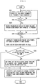
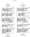
- a procedure is described which selects a frame fragmentation method described in the first to third embodiments or a frame patching method described in the fourth and fifth embodiments in accordance with the number K of transmission-standby data frames.
- Step S001 to S004 it is determined whether the number K of the data frames is 1 or 2 or more (S401).
- the number K of the data frames is 1, X data packets are generated by fragmenting one data frame based on the frame fragmentation method described in the first to third embodiments. The thus generated X data packets are then transmitted simultaneously (S402).
- X data packets are generated by dividing one data frame based on the frame division method described in the first to third embodiments.
- the thus generated X data packets are transmitted simultaneously (S404 and S402). For example, when a ratio of transmission rates of two radio channels is 1:9 and there are two data frames of 1500 bytes, one of two data frames of 300 bytes and 2700 bytes that are generated by the connection and division exceeds Dmax (2296 bytes). Therefore, those two generated data frames cannot be transmitted simultaneously. Instead, data packets (150 bytes and 1350 bytes) generated by dividing each data frame into two are transmitted simultaneously.
- X data packets are generated by the frame patching method described in the fourth and fifth embodiments and are transmitted simultaneously, when the number N of the idle channels is 2 or more (S405 and S406).
- the number N of the idle channels is 1, only one data packet can be transmitted.
- data parts of transmission-standby data frames are aggregated so as not to exceed the maximum data size Dmax, thereby generating one data packet.
- the thus generated one data packet is transmitted by using one radio channel (S407).
- Fig. 14 is a flowchart according to a ninth embodiment of the present invention.
- a procedure is described which selects the frame fragmentation method described in the first to third embodiments or a frame aggregation method described in the sixth and seventh embodiments in accordance with the number K of transmission stand-by data frames.
- Steps S001 to S004 it is determined whether the number K of the data frames is 1 or 2 or more (S401).
- the number K of the data frames is 1, X data packets are generated by fragmenting one data frame based on the frame fragmentation method described in the first to third embodiments and are transmitted simultaneously (S402).
- the number K of the data frames is 2 or more
- data packets are generated from X data frames, respectively, and are transmitted simultaneously (S412 and S413). For example, when all of a plurality of data packets have sizes of 1200 bytes or more, it is not possible to connect a plurality of data packets within Dmax (2296 bytes). Therefore, data packets having the same packet time length are generated from those data frames and are transmitted simultaneously.
- X data packets are generated by the frame aggregation method described in the sixth and seventh embodiments and are transmitted simultaneously, when the number N of the idle channels is 2 or more (S414 and S415).
- the number N of the channels is 1, only one data packet can be transmitted.
- data parts of transmission-standby data frames are aggregated so as not to exceed the maximum data size Dmax, thereby generating one data packet.
- the thus generated one data packet is transmitted by using one radio channel (S416).
- Fig. 2 for example, after two data packets F1a and F1b generated by fragmenting one data frame F1 are transmitted simultaneously; when a next data packet is transmitted, carrier sense is performed.
- a channel occupied time is shortened, although a transmission time is shortened by using simultaneous transmission so as to improve the throughput. That is, the effective throughput of an STA of interest is not always improved.
- the present embodiment and an eleventh embodiment contribute to improvement of the effective throughput of that STA.
- Fig. 15 is a flowchart according to the tenth embodiment of the present invention.
- Fig. 16 shows an exemplary operation in the tenth embodiment of the present invention. It is assumed that two radio channels #1 and #2 are provided between two STAs. In the following description, transmission stand-by data packets in a transmission buffer are data packets transmitted between those two STAs.
- T is set to 0 in default setting (S500).
- An idle radio channel is searched from all available radio channels by carrier sense (S001).
- the number of the detected idle channels is assumed to be N.
- N When one or more idle radio channels are detected, it is searched whether or not there is a transmission-standby data frame in the transmission buffer (S002 and S003).
- S002 and S003 When no transmission-standby data frame is present, the procedure goes back to carrier sense.
- S004 When there is a transmission-standby data frame, the procedure goes ahead (S004).
- N 1, one data packet is generated from one data frame and is then transmitted by using one radio channel, as in the first embodiment. However, this case is not shown in the drawings.
- X data packets are generated from one data frame by the frame fragmentation method described in the first to third embodiments, and are then transmitted simultaneously (S501). Moreover, a transmission time T of those data packets generated from the data frame is calculated and a timer is made to start (S502 and S503). Then, the procedure goes back to Step S003 and next data packets are transmitted simultaneously by using the currently idle channel without performing carrier sense. The transmission of the next data packets is continuously performed until the time T passes after the start of the timer (S504).
- continuous transmission of data packets can be performed in accordance with a Group ACK procedure that is discussed in IEEE802.11 TGe, for example.
- Fig. 17 is a flowchart according to the eleventh embodiment of the present invention.
- the present embodiment has a feature that the number of consecutive transmissions that corresponds to the number of fragmentation X is employed as a period of consecutive transmissions.
- the number of consecutive transmissions is assumed to be C and C is set to 0 in default setting.
- X data packets are generated from one data frame by the frame fragmentation method described in the first to third embodiments, and are transmitted simultaneously (S501).
- the number of consecutive transmissions C is incremented (S511).
- the procedure goes back to Step S003 and next data packets are continuously transmitted simultaneously by using the currently idle channel without performing carrier sense. This transmission is repeated until C reaches X (S512).
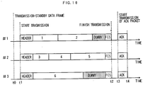
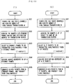
- Fig. 18 is flowcharts according to a twelfth embodiment of the present invention.
- Fig. 18(1) shows a procedure of an AP in a downlink
- Fig. 18(2) shows a procedure of a mobile terminal in an uplink
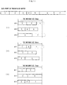
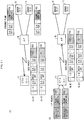
- Fig. 19 shows exemplary frame formats for the downlink and the uplink in the twelfth embodiment.
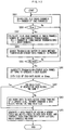
- the AP searches an idle radio channel by carrier sense (S611). Then, the AP acquires the number K of Ethernet frames that are the same in a destination address (an address of a mobile terminal) as the first Ethernet frame in the transmission buffer (S612). Then, the AP selects N (1 ⁇ N ⁇ K) Ethernet frames that are to be transmitted in one lump from the K Ethernet frames within a range in which the selected Ethernet frames can be accommodated in one wireless packet (S613). The AP also acquires a source address (SA) from a header of each of the N Ethernet frames (S614).
- SA source address
- the AP adds control information to a frame body (IP packet) of each of the N Ethernet frames.
- the control information contains the source address SA of the corresponding Ethernet frame.
- the AP generates a wireless packet that contains a frame body obtained by aggregating the frame bodies of the N Ethernet frames with the control information added thereto and also contains a MAC header and FCS added to the frame body.
- the MAC header contains a destination address DA, BSSID, and a source addresses SA.
- the AP transmits the thus generated wireless packet (S615).
- the frame body of that wireless packet is generated so as not to exceed the maximum data size that can be transmitted in one MAC frame (e.g., 2296 bytes).
- Fig. 19(1) shows an example in which an AP 10 generates one wireless packet from Ethernet frames transmitted from servers 12 and 13 and transmits it in one lump.
- an identifier for specifying a frame format "S1" as the destination address DA, "AP” as BSSID, and a given address (e.g., AP) as the source address SA are set.
- the frame body of the wireless packet accommodates the frame body (IP packet) of the Ethernet frame transmitted from the server 12 with its source address SA (S2) added thereto and the frame body (IP packet) of the Ethernet frame transmitted from the server 13 with its source address SA (S3) added thereto.
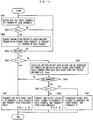
- the mobile terminal searches an idle radio channel by carrier sense, when IP packets are accumulated in the transmission buffer (S621). Then, the mobile terminal acquires the number K of IP packets in the transmission buffer that are sent to the same AP (S622). The mobile terminal selects N (1 ⁇ N ⁇ K) IP packets that are to be transmitted in one lump from the K IP packets within a range in which the selected IP packets can be accommodated in one wireless packet (S623). The mobile terminal acquires a destination address DA from an IP header of each of the N IP packets (S624). Then, the mobile terminal adds control information to a frame body of each of the N IP packets. The control information contains the destination address DA of the corresponding IP packet.
- the mobile terminal then generates a wireless packet that contains a frame body obtained by aggregating the N frame bodies with the control information added thereto and also contains a MAC header and FCS added to the frame body.
- the MAC header contains BSSID, a source address SA, and a destination address DA.
- the mobile terminal transmits the thus generated wireless packet (S625).
- the frame body of that wireless packet is generated so as not to exceed the maximum data size that can be transmitted in one MAC frame (e.g., 2296 bytes).
- Fig. 19(2) shows an example in which one wireless packet is generated from IP packets to servers 12 and 13 in a mobile terminal 11 and is transmitted in one lump.
- an identifier for specifying a frame format "AP" as BSSID, "S1" as the source address SA, and a given address (e.g., AP) as the destination address DA are set.
- the frame body of the wireless packet accommodates the IP packet to the server 12 with its destination address DA (S2) added thereto and the IP packet to the server 13 with its destination address DA (S3) added thereto.
- Fig. 20 includes flowcharts according to the thirteenth embodiment of the present invention.
- Fig. 20(1) shows a procedure of an AP in a downlink
- Fig. 20(2) shows a procedure of a mobile terminal in an uplink
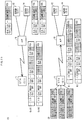
- Fig. 21 shows frame formats for the downlink and the uplink in the thirteenth embodiment.
- the AP searches an idle radio channel by carrier sense and acquires a number of simultaneous transmissions M (S631).
- a case is considered in which simultaneous transmission is performed using a plurality of radio channels.
- MIMO number or a number corresponding to a total number of MIMOs of a plurality of radio channels in the case where MIMO is used may be used as the number of simultaneous transmissions M.
- the AP acquires the number K of Ethernet frames that are the same in a destination address (an address of a mobile terminal) as the first Ethernet frame in the transmission buffer (S632). Then, the AP selects M (M ⁇ K) Ethernet frames that are to be transmitted simultaneously from the K Ethernet frames (S633), and acquires a source address (SA) from a header of each of the M Ethernet frames (S634). Then, the AP adds control information to a frame body (IP packet) of each of the M Ethernet frames. The control information contains the source address SA of the corresponding Ethernet frame.
- the AP further adds a MAC header containing a destination address DA, BSSID, and a source address SA and FCS to each of the M Ethernet frames, thereby generating wireless packets.
- the AP transmits the thus generated wireless packets simultaneously (S635).
- Fig. 21(1) shows an example in which an AP 10 generates wireless packets from Ethernet frames respectively transmitted from servers 12 and 13 and transmits those wireless packets simultaneously by using two radio channels.
- a wireless packet transmitted on a radio channel #1 "S1" as the destination address DA, "AP” as BSSID, and "S2" as the source address SA are set.
- a wireless packet transmitted on a radio channel #2 "S1" as the destination address DA, "AP” as BSSID, and "S3" as the source address SA are set.
- the frame bodies of the wireless packets accommodate the frame bodies (IP packets) of the Ethernet frames transmitted from the servers 12 and 13 with their source addresses SA, respectively. Please note that the source address SA that is put before the frame body may be omitted.
- the mobile terminal searches an idle radio channel by carrier sense and acquires the number of simultaneous transmissions M (S641). Then, the mobile terminal acquires the number K of IP packets in the transmission buffer that are sent to the same AP (S642). The mobile terminal selects M (M ⁇ K) IP packets that are to be transmitted simultaneously from the K IP packets (S643) and acquires a destination address DA from an IP header of each of the M IP packets (S644). Then, the mobile terminal generates wireless packets by adding control information containing the destination address DA of the corresponding IP packet to a frame body of each of the M IP packets and further adding a MAC header and FCS. The MAC header contains BSSID, a source address SA, and a destination address DA. The mobile terminal transmits the thus generated wireless packets simultaneously (S645).
- Fig. 21(2) shows an example in which a mobile terminal 11 generates wireless packets from IP packets to servers 12 and 13, respectively, and transmits those wireless packets simultaneously by using two radio channels.
- MAC header of a wireless packet transmitted on a radio channel #1 "AP” as BSSID, "S1” as the source address SA, and "S2" as the destination address DA are set.
- AP as BSSID, "S1” as the source address SA, and "S3" as the destination address DA are set.
- the frame bodies of the wireless packets accommodate the IP packets to be transmitted to the servers 12 and 13 with their destination addresses DA, respectively.
- the destination address DA that is put before the frame body may be omitted.
- Fig. 22 includes flowcharts according to a fourteenth embodiment of the present invention.
- Fig. 22(1) shows a procedure of an AP in a downlink
- Fig. 22(2) shows a procedure of a mobile terminal in an uplink
- Fig. 23 shows frame formats for the downlink and the uplink in the fourteenth embodiment.
- the AP searches an idle radio channel by carrier sense and acquires a number of simultaneous transmissions M (S651).
- a case is considered in which simultaneous transmission is performed using a plurality of radio channels.
- MIMO number or a number corresponding to a total number of MIMOs of a plurality of radio channels in the case where MIMO is used may be used as the number of simultaneous transmissions M.
- the AP acquires the number K of Ethernet frames that are the same in a destination address (an address of a mobile terminal) as the first Ethernet frame in the transmission buffer (S652). Then, the AP selects N (1 ⁇ N ⁇ K) Ethernet frames that are to be transmitted simultaneously from the K Ethernet frames within a range in which the selected Ethernet frames can be accommodated in M wireless packets (S653). The AP also acquires a source address SA from a header of each of the N Ethernet frames (S654). Then, the AP adds control information containing the source address SA of the corresponding Ethernet frame to a frame body (IP packet) of each of the N Ethernet frames, and connects the N frames bodies so as to generate a first block (S655).
- IP packet frame body
- the AP divides the first block into M so as to generate M blocks (S656).
- the AP generates M wireless packets that accommodate the M blocks as frame bodies, respectively, by adding a MAC header that contains a destination address DA, BSSID, and a source address SA, and FCS to each of the frame bodies.
- the AP transmits the M wireless packets simultaneously (S657).
- the frame body of the wireless packet is generated so as not to exceed the maximum data size that can be transmitted in one MAC frame (e.g., 2296 bytes).
- Fig. 23(1) shows an example in which an AP 10 converts three Ethernet frames respectively transmitted from servers 12 to 14 into two wireless packets and transmits those wireless packets simultaneously by using two radio channels.
- an Ethernet frame transmitted from the server 12 and a part of an Ethernet frame transmitted from the server 13 are aggregated to each other, and a remaining part of the Ethernet frame from the server 13 and an Ethernet frame from the server 14 are aggregated to each other.
- "S1" as the destination address DA, "AP" as BSSID, and a given address (e.g., AP) as the source address SA are set.
- the mobile terminal searches an idle radio channel by carrier sense and acquires the number of simultaneous transmissions M (S661). Then, the mobile terminal acquires the number K of IP packets in the transmission buffer that are sent to the same AP (S662). The mobile terminal selects N (1 ⁇ N ⁇ K) IP packets that are to be transmitted simultaneously from the K IP packets within a range in which the selected IP packets can be accommodated in M wireless packets (S663). The mobile terminal also acquires a destination address DA from an IP header of each of the N IP packets (S664). Then, the mobile terminal adds control information to each of the N IP packets.
- the control information contains the destination address DA of the corresponding IP packet.
- the mobile terminal then connects the N IP packets so as to generate a first block (S665) and thereafter generates M blocks by dividing the first block into M (S666). Then, the mobile terminal generates wireless packets by adding a MAC header and FCS to each of the M blocks serving as frame bodies of the wireless packets.
- the MAC header contains BSSID, a source address SA, and a destination address DA. The mobile terminal transmits those wireless packets simultaneously (S667).
- Fig. 23(2) shows an example in which a mobile terminal 11 generates wireless packets from IP packets to the servers 12 to 14 and transmits those wireless packets simultaneously by using two radio channels.
- an IP packet to the server 12 and a part of an IP packet to the server 13 are aggregated to each other, and a remaining part of the IP packet to the server 13 and an IP packet to the server 14 are aggregated to each other.
- "AP" as BSSID, "S1" as the source address SA, and a given address (e.g., AP) as the destination address DA are set.
- AP as BSSID
- S1 as the source address SA
- a given address e.g., AP
- the IP packets to the servers 12 to 14 are accommodated with the destination addresses DA thereof, while being fragmented, if necessary.
- Fig. 24 includes flowcharts according to a fifteenth embodiment of the present invention.
- Fig. 24(1) shows a procedure of an AP in a downlink
- Fig. 24(2) shows a procedure of a mobile terminal in an uplink
- Fig. 25 shows frame formats for the downlink and the uplink in the fifteenth embodiment.
- the AP searches an idle radio channel by carrier sense and acquires a number of simultaneous transmissions M (S671).
- a case is considered in which simultaneous transmission is performed using a plurality of radio channels.
- MIMO number or a number corresponding to a total number of MIMOs of a plurality of radio channels in the case where MIMO is used may be used as the number of simultaneous transmissions M.
- the AP acquires the number K of Ethernet frames that are the same in a destination address (an address of a mobile terminal) as the first Ethernet frame in the transmission buffer (S672).
- the AP selects N (1 ⁇ N ⁇ K) Ethernet frames for generating M wireless packets, by aggregating the K Ethernet frames in order within a range in which the selected Ethernet frames can be accommodated in the respective wireless packets (S673).
- the AP also acquires a source address SA from a header of each of the N Ethernet frames (S674).
- the AP adds control information containing the source address SA of the corresponding Ethernet frame to a frame body (IP packets) of each of the N Ethernet frames and aggregates the N frame bodies to one another, and generates M wireless packets in each of which a MAC header containing a destination address DA, BSSID, and a source address SA, and FCS are added.
- the AP then transmits the M wireless packets simultaneously (S675).
- the packet time lengths of the wireless packets are different, the packet time lengths of all the wireless packets are made the same by adding dummy data, if necessary.
- Fig. 25(1) shows an example in which an AP 10 converts three Ethernet frames respectively transmitted from servers 12 to 14 into two wireless packets and transmits those wireless packets simultaneously by using two radio channels.
- an Ethernet frame from the server 12 and an Ethernet frame from the server 13 are aggregated to each other, and an Ethernet frame from the server 14 is aggregated to dummy data.
- "S1" as the destination address DA, "AP" as BSSID, and a given address (e.g., AP) as the source address SA are set.
- the mobile terminal searches an idle radio channel by carrier sense and acquires the number of simultaneous transmissions M (S681). Then, the mobile terminal acquires the number K of IP packets in the transmission buffer that are sent to the same AP (S682).
- the mobile terminal selects N (1 ⁇ N ⁇ K) IP packets for generating M wireless packets by aggregating the K IP packets in order within a range in which the selected IP packets can be accommodated in the respective wireless packets (S683).
- the mobile terminal also acquires a destination address DA from an IP header of each of the N IP packets (S684).
- the mobile terminal generates wireless packets by adding control information containing the destination address DA of the corresponding IP packet to each of the N IP packets, aggregating the N IP packets, and further adding MAC headers each containing BSSID, a source address SA, and a destination address DA, and FCSs.
- the mobile terminal transmits those wireless packets simultaneously (S685).
- Fig. 25(2) shows an example in which a mobile terminal 11 generates wireless packets from IP packets to servers 12 to 14 and transmits those wireless packets simultaneously by using two radio channels.
- an IP packet to the server 12 and an IP packet to the server 13 are aggregated to each other, and an IP packet to the server 14 is aggregated to dummy data.
- "AP" as BSSID, "S1" as the source address SA, and a given address (e.g., AP) as the destination address DA are set.
- AP as BSSID
- S1 as the source address SA
- a given address e.g., AP
- the IP packets to the servers 12 to 14 are accommodated in order with the destination addresses DA thereof.
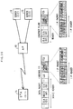
- Fig. 26 shows an exemplary frame format according to a sixteenth embodiment of the present invention.
- a wireless packet communication method corresponding to any of the twelfth to fifteenth embodiments is applied as a method for transferring wireless packets between STAs in a Multi-Hop Wireless Network.
- a frame aggregation method of the twelfth embodiment is applied.
- the thirteenth to fifteenth embodiments can be applied in a similar manner.
- Fig. 26 shows the case where an STA (S1) 21 and an STA (S2) 22 transmit wireless packets to an STA (S4) 24 via an STA (S3) 23.
- STA 23 selects two data frames respectively transmitted from the STAs 21 and 22 to the STA 24, adds addresses (S1 and S2) of the STAs 21 and 22 as source addresses SA to frame bodies of the two data frames, respectively, aggregates the frame bodies with the corresponding source addresses SA to each other, generates one wireless packet by adding a MAC header, and transmits the wireless packet in one lump.
- the transmission in the opposite direction can be carried out in a similar manner.
- the STA 24 adds addresses of the STAs 21 and 22 (S1 and S2) as destination addresses DA to frame bodies of the data frames, respectively, aggregates the frame bodies, generates one wireless packet by adding a MAC header, and transmits that wireless packet in one lump.
- Fig. 27 shows an exemplary frame format according to a seventeenth embodiment of the present invention.
- the wireless packet communication method corresponding to any of the twelfth to fifteenth embodiments is applied as a method for transferring wireless packets between STAs in a Wireless Bridge.
- the frame aggregation method of the twelfth embodiment is applied.
- the methods of the thirteenth to fifteenth embodiments can be applied in a similar manner.
- Fig. 27 shows the case where, when a terminal (S1) 31 and a terminal (S3) 32 transmit Ethernet frames to a terminal (S3) 33, an STA (API) 41 connected to the terminals 31 and 32 and an STA (AP2) 42 connected to the terminal 33 intervene.
- the STA 41 selects two Ethernet frames respectively transmitted from the terminals 31 and 32 to the terminal 33, adds addresses (S1 and S2) of the terminals 31 and 32 as source addresses SA to frame bodies of the two Ethernet frames, respectively, aggregates the frame bodies with the corresponding source addresses SA to each other, generates one wireless packet by adding a MAC header, and transmits the wireless packet in one lump.
- the transmission in the opposite direction can be carried out in a similar manner.
- the STA 42 When transferring Ethernet frames to the terminals 31 and 32 that are accumulated in the transmission buffer, to the STA 41, the STA 42 adds addresses (S1 and S2) of the terminals 31 and 32 as destination addresses DA to frame bodies of the selected Ethernet frames, respectively, aggregates the frame bodies with the destination addresses DA to each other, generates one wireless packet by adding a MAC header, and transmits that wireless packet in one lump.
- the present invention it is possible to easily generate a plurality of data packets having the same packet time length from transmission-standby data frames in a transmission buffer in accordance with the number of the transmission-standby data frames and the number of idle channels, while effectively using the maximum size of a data field that can be accommodated in a MAC packet.
- a plurality of radio channels are idle at the same time, the thus generated data packets can be transmitted simultaneously and the maximum throughput can be largely improved.
Description
- The present invention relates to a wireless packet communication method for transmitting a plurality of data packets simultaneously between two wireless stations (hereinafter STAs) using a plurality of radio channels and Multiple Input Multiple Output (hereinafter MINO). More particularly, the present invention relates to a wireless packet communication method for generation of a plurality of data packets to be transmitted simultaneously.
- In a conventional wireless packet communication method, a radio channel to be used is determined in advance. Prior to transmission of data packets, carrier sense is performed to detect whether or not that radio channel is idle. Only when that radio channel is idle, one data packet is transmitted. This management process enables a plurality of STAs to share one radio channel in a staggered manner (1) International Standard ISO/IEC 8802-11 ANSI/EEE Std. 802.11, 1999 edition, Information technology - Telecommunications and information exchange between system - local and metropolitan area networks - Specific requirements - part 11: Wireless LAN Medium Access Control (MAC) and Physical Layer (PHY) specifications, (2) Low-powered Data Communication System/Broadband Mobile Access Communication System (CSMA) Standard, ARIB STD-T71 version 1.0, Association of Radio Industries and Businesses, settled in 2000).
- In order to improve a maximum throughput of the above wireless packet communication method, a method is known which broadens the frequency band per radio channel so as to increase the data transmission rate in the PHY layer.
- However, it is necessary to provide a transmission deferral duration of a predetermined length that is independent of the data transmission rate in the PHY layer immediately after the transmission of a packet in order to avoid collision of packets, as pointed out, for example, in an article (lizuka et al., "5 GHz Wireless LAN System Based on the IEEE802.11a standard - Packet Transmission Characteristics -", B-5-124, Proceedings of the Electronics Information and Communication Engineers, Society Conference 2000, September 2000). When such a transmission deferral duration is provided, the transmission efficiency of data packets (a ratio of the maximum throughput to the data transmission rate in the PHY layer) decreases with the increase in the data transmission rate in the PHY layer. Thus, it is difficult to significantly improve the throughput by only increasing the data transmission rate in the PHY layer.
- On the other hand, the application of a MIMO technique (Kurosaki et al., "100Mbit/s SDM-COFDM over MIMO Channel for Broadband Mobile Communications", Technical Reports of the Institute of Electronics, Information and Communication Engineers, A . P 2001-96, RCS2001-135(2001-10)) has been considered for improving the maximum throughput without broadening the frequency band per radio channel. In the MIMO technique, different data packets are transmitted from a plurality of antennas on the same radio channel at the same time. The data packets transmitted at the same time on the same radio channel are received by digital signal processing that can deal with the difference in propagation coefficients of the respective data packets received by a plurality of wireless antennas in an opposed STA. A MIMO number is determined in accordance with the propagation coefficients and the like.
- On the other hand, in the case where each STA has a plurality of wireless network interfaces and can use a plurality of radio channels, different radio channels can be used between a plurality of STAs. In this case, improvement of the throughput is promising, as compared with communication performed by time-dividing one radio channel.
- However, when the center frequencies of a plurality of radio channels used at the same time are close to each other, the effect of leakage power, which leaks from one radio channel to a frequency band used by another radio channel, becomes large. In general, in the case of transmitting a data packet, after a transmit-side STA sends a data packet, a receive-side STA sends back an acknowledge packet (ACK packet, NACK packet) for the received data packet to the transmit-side STA. When the transmit-side STA tries to receive that acknowledge packet, the effect of leakage power from another radio channel that carries out transmission at the same time becomes a problem.
- For example, the case is considered where the center frequencies of
radio channels # 1 and #2 are close to each other and the transmission time is different between data packets that are transmitted simultaneously from theradio channels # 1 and #2, as shown inFig. 28 . In the shown example, the data packet transmitted from theradio channel # 1 is shorter. Thus, when an ACK packet for that data packet is received, the data packet on theradio channel # 2 is still in transit. Therefore, theradio channel # 1 may not receive the ACK packet because of leakage power from theradio channel # 2. In this situation, the throughput cannot be improved even if transmission is carried out by using a plurality of radio channels at the same time. - If transmission rates of the respective radio channels are the same, the above situation occurs because of a difference in packet time length (transmission time = data size) between data packets. Considering the transmission rates of the respective radio channels, the above situation occurs because of the difference in packet time length (transmission time = data size/transmission rate) between data packets.
- In a wireless LAN system or the like, the data size of a data frame input from a network is not constant. Thus, in the case where input data frames are sequentially converted into data packets and are transmitted, the packet time length (transmission time) of each data packet also changes. Therefore, even when a plurality of data packets are transmitted at the same time, as shown in
Fig. 28 , it is highly likely that a packet time length difference occurs between the data packets and causes a failure in the receiving of the ACK packet. - Moreover, in a wireless LAN system operating in accordance with IEEE802.11 Standard, for example, a data frame input from a wired network (e.g., Ethernet (registered trademark) frame) is converted into a MAC (Media Access Control) frame and a data packet generated from that MAC frame is transmitted as a wireless packet to a wireless line.
- In a conventional system, one data frame is converted into one MAC frame from which one data packet is generated. Therefore, even if the data size of a data field in a data frame is small, that data frame is converted into one MAC frame and is transmitted as one data packet (wireless packet). For example, the maximum size of the data field of a MAC frame in accordance with IEEE802.11 Standard is 2296 bytes, whereas the data size of the data field of an Ethernet (registered trademark) frame that is typically used as a data frame is limited to 1500 bytes. Therefore, even if the Ethernet (trademark) frame has the maximum size, that Ethernet frame has some leftover in the maximum size (2296 bytes) of the data field of the MAC frame. That is, the conventional system does not effectively use the maximum data size that can be transmitted in one MAC frame, and has a limitation in the improvement of the throughput.
- As described above, in order to further improve the throughput, it is necessary to overcome the problem of different packet time lengths in the case of simultaneous transmission using a plurality of radio channels (i.e., different data sizes when the transmission rates of the radio channels are the same) and the problem of inefficiency in the case where the data size of a data frame is smaller than the maximum size of a data field of a MAC frame.
-
Fig. 29 shows an exemplary configuration of a wireless LAN system. InFig. 29 , a mobile terminal (address: S1) 11, a server (address: S2) 12, and a server (address: S3) 13 are connected through an access point (hereinafter AP) (address: AP) 10. Themobile terminal 11 and the AP 10 are connected to each other through a wireless line on which wireless packets are transmitted. The AP 10 and theservers servers mobile terminal 11 is called as a "downlink", and a transmission direction from themobile terminal 11 to theservers -
Fig. 30 shows a frame format for the downlink of the wireless LAN system. InFig. 30 , an Ethernet frame transmitted from theserver server 12 to themobile terminal 11, a destination address DA and a source address SA are set to "S1" and "S2", respectively. The frame body accommodates an IP packet for which the destination address DA and the source address SA are set to "S1" and "S2", respectively. - The Ethernet frame transmitted from the
server mobile terminal 11. The wireless packet contains a MAC header, a frame body, FCS, and the like. In the MAC header of the wireless packet corresponding to the Ethernet frame transmitted from theserver 12, "S1" is set as a destination address DA in a PHY layer, "AP" is set as BSS (Basic service set) ID corresponding to a source address in the PHY layer, and "S2" is set as a source address SA. The frame body accommodates an IP packet for which "S1" is set as the destination address DA and "S2" is set as the source address SA. -
Fig. 31 shows a frame format for the uplink of the wireless LAN system. InFig. 31 , themobile terminal 1 1 generates an IP packet to theserver server 12, "S2" is set as a destination address DA and "S1" is set as a source address SA. A wireless packet transmitted from themobile terminal 1 1 to the AP 10 contains a MAC header, a frame body, FCS, and the like. In the MAC header of the wireless packet accommodating the IP packet to theserver 12, BSSID corresponding to a destination address in the PHY layer is set to "AP", a source address SA in the PHY layer is set to "S1", and a destination address DA is set to "S2". The frame body accommodates the IP packet for which the destination address DA is set to "S2" and the source address SA is set to "S1". - The wireless packet transmitted from the
mobile terminal 1 1 is converted into an Ethernet frame in the AP 10 and is transmitted to theserver server 12, a destination address DA and a source address SA are set to "S2" and "S1", respectively. The frame body accommodates the IP packet for which the destination address DA and the source address SA are set to "S2" and "S1", respectively. - A conventional AP generates one wireless packet from one Ethernet frame to the mobile terminal and transmits that wireless packet on the downlink of the PHY layer from the AP to the mobile terminal. From a viewpoint of improving transmission efficiency, a method is considered to be effective that generates one or more wireless packets from a plurality of Ethernet frames transmitted from a plurality of servers to the same mobile terminal and then transmits those one or more wireless packets in one lump.
- Similarly, a conventional mobile terminal generates one wireless packet from one IP packet to a server and transmits that wireless packet on the uplink of the PHY layer from the mobile terminal to the AP. From a viewpoint of improving transmission efficiency, a method is considered to be effective that generates one or more wireless packets from a plurality of IP packets to the same server and transmits those one or more wireless packets in one lump.
Moreover, for the uplink of the PHY layer from the mobile terminal to the AP, another method can be considered, in which one or more wireless packets are generated from not only IP packets to the same servers but also IP packets that are transmitted to different servers through the same AP, and are transmitted in one lump. In the mobile terminal, IP packets to the same server can be found by referring to their destination addresses DA. It is also possible to find whether or not a plurality of IP packets to different servers go through the same AP by checking their destination addresses DA against the AP address. -
JP H05 35624 A -
US 2003/074669 A1 relates to on-demand data transmission. In the described system, a plurality of section packet data are formed by performing packet data transmission/reception and dividing encoded data into a plurality of data segments. The plurality of section packet data are coded by performing a specific coding process on each of the plurality of data segments, and the plurality of section packet data arc reformed into the data segments by performing a specific decoding process. The plurality of section packet data are then stored in a data memory. Each of the plurality of section packet data is repeatedly retrieved from the data memory, and the resulting sequences of section packet data are then sequentially transmitted on the corresponding data transmission channels. - It is an object of the present invention to provide a wireless packet communication method that can easily generate a plurality of data packets having the same packet time length in the case of transmitting a plurality of data packets simultaneously between two STAs by using a plurality of radio channel at the same time. It is another object of the present invention to provide a wireless packet communication method that can generate a plurality of data packets from one Ethernet frame or IP packet or from a plurality of Ethernet frames or IP packets to the same destination for each of a downlink and an uplink in a PHY layer between a mobile terminal and an access point (hereinafter AP) or between STAs.
- The invention is defined by the independent claims. Preferred embodiments are set out in the dependent claims.
- The invention relates to the third, tenth and eleventh embodiments discussed below.
- The other embodiments do not form part of the invention but are useful for understanding the invention.
-
-
Fig. 1 is a flowchart of a procedure according to a first embodiment of the present invention; -
Fig. 2 is a time chart of an exemplary operation in the first embodiment of the present invention; -
Fig. 3 is a flowchart of a procedure according to a second embodiment of the present invention; -
Fig. 4 is a flowchart of a procedure according to a third embodiment of the present invention; -
Fig. 5 is a time chart of an exemplary operation in the third embodiment of the present invention; -
Fig. 6 is a flowchart of a procedure according to a fourth embodiment of the present invention; -
Fig. 7 is a time chart of an exemplary operation in the fourth embodiment of the present invention; -
Fig. 8 is a flowchart of a procedure according to a fifth embodiment of the present invention; -
Fig. 9 is a flowchart of a procedure according to a sixth embodiment of the present invention; -
Fig. 10 is a time chart of an exemplary operation in the sixth embodiment of the present invention; -
Fig. 11 is a diagram showing examples of aggregation of data frames as exemplary operations in the sixth embodiment of the present invention; -
Fig. 12 is a flowchart of a procedure according to a seventh embodiment of the present invention; -
Fig. 13 is a flowchart of a procedure according to an eighth embodiment of the present invention; -
Fig. 14 is a flowchart of a procedure according to a ninth embodiment of the present invention; -
Fig. 15 is a flowchart of a procedure according to a tenth embodiment of the present invention; -
Fig. 16 is a time chart of an exemplary operation in the tenth embodiment of the present invention; -
Fig. 17 is a flowchart of a procedure according to an eleventh embodiment of the present invention; -
Fig. 18 is flowcharts of procedures according to a twelfth embodiment of the present invention; -
Fig. 19 is a diagram showing frame formats for an uplink and a downlink in the twelfth embodiment of the present invention; -
Fig. 20 includes flowcharts of procedures according to a thirteenth embodiment of the present invention; -
Fig. 21 is a diagram showing frame formats for an uplink and a downlink in the thirteenth embodiment of the present invention; -
Fig. 22 includes flowcharts of procedures according to a fourteenth embodiment of the present invention; -
Fig. 23 is a diagram showing frame formats for an uplink and a downlink in the fourteenth embodiment of the present invention; -
Fig. 24 includes flowcharts of procedures according to a fifteenth embodiment of the present invention; -
Fig. 25 is a diagram showing frame formats for an uplink and a downlink in the fifteenth embodiment of the present invention; -
Fig. 26 is an exemplary frame format according to a sixteenth embodiment of the present invention; -
Fig. 27 is an exemplary frame format according to a seventeenth embodiment of the present invention; -
Fig. 28 is a time chart for explaining a problem in the case where center frequencies of a plurality of radio channels are close to each other; -
Fig. 29 is a diagram showing an exemplary configuration of a wireless LAN system; -
Fig. 30 is a diagram showing an exemplary frame format for a downlink of the wireless LAN system; and -
Fig. 31 is a diagram showing an exemplary frame format for an uplink of the wireless LAN system. -
Fig. 1 is a flowchart according to a first embodiment of the present invention.Fig. 2 shows an exemplary operation in the first embodiment of the present invention. Please note that a transmission-standby data frame in a transmission buffer in the following description is a data frame transmitted between two STAs. - An idle radio channel is searched from all available radio channels by carrier sense (S001). The number of the detected idle channels is assumed to be N. In the case where one or more idle radio channels are detected, it is searched whether or not there is a transmission-standby data frame in a transmission buffer (S002 and S003). When there is no transmission-standby data frame, the procedure goes back to the carrier sense. When there is any transmission-standby data frame, the procedure goes ahead (S004). In the case where N = 1, one data block is generated from one data frame (S005 and S006). A header field containing control information such as destination information and an FCS (Frame Check Sequence) part containing an error checking code (hereinafter, referred to as "a header and the like") are added to the thus generated data block, thereby generating a data packet. The data packet is transmitted by using one radio channel (S007).
- A transmission rate of each radio channel may be fixed in advance, or may be set on a case-by-case basis by selecting one of a plurality of transmission rates determined in advance, for example, based on the quality of a wireless line.
- In the case where N ≥ 2, the transmission rates of the respective radio channels are checked (S008). At this time, the number X of data packets that are to be transmitted simultaneously is determined (X ≤ N). When the transmission rates of the respective radio channels are the same, a data part of one data frame is fragmented into X so as to generate X data blocks having the same packet time length (S009). When two radio channels are idle, for example, two data packets can be transmitted at the same time. Thus, as shown in
Fig. 2(1) , the data part of one data frame is equally fragmented so as to generate two data blocks. - On the other hand, when the transmission rates of the respective radio channels are different, the data part of one data frame is fragmented into X at a size ratio corresponding to the transmission rates, so as to generate X data blocks having the same packet time length (transmission time) (S010). For example, when two radio channels (#1 and #2) are idle and their transmission rates are 6 Mbit/s and 12 Mbit/s, respectively, the data part of one data frame is fragmented at a packet size ratio of 1:2 so as to generate two data blocks, as shown in
Fig. 2(2) . - After the X data blocks are generated in Step S009 or S010, X data packets are generated by adding a header and the like to each of the X data blocks. The thus generated X data packets are transmitted simultaneously by using X radio channels (S011). The data packets transmitted simultaneously have the same packet time length, as shown in
Fig. 2 . Therefore, transmission of the X data packets terminates at the same time. Thus, ACK packets after that transmission can be received without being affected by leakage power. - If a plurality of data packets transmitted simultaneously have different packet time lengths, a termination time of transmission of each data packet is different by a time corresponding to a difference of the packet time length. Thus, a time at which each ACK packet is received is different by the time corresponding to the difference of the packet time length. However, when the difference of the packet time length between the data packets is sufficiently small and the difference of the transmission termination time between the data packets is shorter than a time until receiving of an ACK packet starts, each ACK packet can be received without being affected by leakage power. In other words, it is not always necessary that the packet time lengths of the data packets to be transmitted simultaneously are strictly the same. The phrase "having the same packet time length" in the claims is written considering the above.
-
Fig. 3 is a flowchart according to a second embodiment of the present invention. - In the present embodiment, when the transmission rates of the idle radio channels are different in the first embodiment, a smallest one of the transmission rates is selected as a common transmission rate (S012). In this case, it is not necessary to perform the process in Step S010 of the first embodiment. One data frame is fragmented into X in Step S009 so as to generate X data blocks having the same packet time length.
-
Fig. 4 is a flowchart according to a third embodiment of the present invention.Fig. 5 shows an exemplary operation in the third embodiment of the present invention. It is assumed thatradio channels # 1 and #2 are provided between two STAs. A transmission stand-by data packet in a transmission buffer in the following description is a data packet to be transmitted between those two STAs. - A feature of the present embodiment is to use MIMO in the first embodiment. An idle radio channel is searched from all available radio channels by carrier sense (S001). The number of the detected idle channels is assumed to be N. In the case where one or more idle radio channels are detected, a total number of MIMOs is calculated as "a number of simultaneous transmissions" (S002 and S101). For simplification, it is assumed that the MIMO numbers of the respective radio channels are the same and the number of simultaneous transmissions is a product (NL) of the number N of the idle channels and the MIMO number L.
- Next, it is searched whether or not there is a transmission-standby data frame in a transmission buffer (S003). When there is no transmission-standby data frame, the procedure goes back to carrier sense. When there is a transmission-standby data frame, the procedure goes ahead (S004). In the case where N = 1, X data packets are generated by fragmenting one data frame into X and are then transmitted by using one radio channel and MIMO (S005, S102, and S103).
- In the case where N ≥ 2, transmission rates of the respective radio channels are checked (S008). The number X (X ≤ NL) of data packets to be transmitted simultaneously is also determined. When the transmission rates of the respective radio channels are the same, a data part of one data frame is fragmented into X so as to generate X data blocks having the same packet time length (S104). For example, when two radio channels are idle and the MIMO number L of each radio channel is 2, four data packets can be transmitted at the same time. Therefore, the data part of one data frame is equally fragmented to generate four data blocks, as shown in
Fig. 5(1) . - On the other hand, when the transmission rates of the respective radio channels are different, the data part of one data frame is fragmented into N at a size ratio corresponding to the transmission rates, thereby generating N data blocks (S105). Then, each of the N data block is fragmented into L to generate X (= NL) data blocks having the same packet time length (transmission time) (S106). For example, when two radio channels (#1 and #2) are idle, transmission rates thereof are 6 Mbit/s and 12 Mbit/s, respectively, and the MIMO number L of each channel is 2, the data part of one data frame is fragmented at a packet size ratio of 1:2, and each of the resultant data blocks is equally fragmented, thereby generating four data blocks, as shown in
Fig. 5(2) . In the case where transmission rates of respective transmission media for MIMO are different, it is only necessary to perform fragmentation in accordance with the transmission rates in a similar manner. - After the X data blocks are generated in Step S104 or S106, X data packets are generated by adding a header and the like to each of the X data blocks. The X data packets are transmitted simultaneously by using ceil (X/L) radio channels and MIMO (S107), where ceil (x) represents the smallest integer equal to or larger than x (i.e., an integer obtained by rounding up x). The simultaneous transmission of the data packets terminates at the same time, because those data packets have the same packet time length, as shown in
Fig. 5 . Thus, ACK packets after that transmission can be received without being affected by leakage power. -
Fig. 6 is a flowchart according to a fourth embodiment of the present invention.Fig. 7 shows an exemplary operation in the fourth embodiment of the present invention. In this example, it is assumed thatradio channels # 1 and #2 are provided between two radio channels. In the following description, a transmission stand-by data packet in a transmission buffer is a data packet transmitted between those two STAs. - An idle radio channel is searched from all available radio channels by carrier sense (S001). The number of the detected idle channels is assumed to be N. When one or more idle radio channels are detected, it is then searched whether or not there is a transmission-standby data frame in the transmission buffer (S002 and S003). When there is no transmission-standby data frame, the procedure goes back to carrier sense. When there is a transmission-standby data frame, the procedure goes ahead (S004).
- First, the number X (X ≤ N) of radio channels to be used for simultaneous transmission is determined, and transmission rates of those radio channels are checked (S008). Although it is assumed that N ≥ 2 in the following description, a similar description can be applied to the case where N = 1 by setting X to 1. When the transmission rates of the respective radio channels are the same, the maximum size Dmax that can be transmitted in one MAC packet is determined, and a total of the maximum data size Dmax • X in the case where simultaneous transmission is performed using X radio channels is calculated. Then, data parts of transmission-standby data frames are connected so as not to exceed the above total of the maximum data size (S201). The connected data frames are divided into X so as to generate X data blocks having the same packet time length (S202).
- On the other hand, when the transmission rates of the respective radio channels are different, the maximum size in each radio channel Dmax • Ri/Rmax is determined, assuming that a transmission rate of each radio channel is Ri (i is an integer from 1 to X), the maximum transmission rate is Rmax, and the maximum size of data that can be transmitted in one MAC packet is Dmax. In addition, the total of the maximum data size when simultaneous transmission is performed using X radio channels is calculated. Then, data parts of transmission-standby data frames are connected so as not to exceed the above total of the maximum data size (S203). The connected data frames are divided into X at a size ratio corresponding to the transmission rates Ri, thereby generating X data blocks having the same packet time length (transmission time) (S204). After the X data blocks are generated in Step S202 or S204, X data packets are generated by adding a header and the like to each data block. The X data packets are transmitted simultaneously using X radio channels (S205).
- A process for generating two data packets from three data frames in the case where two radio channels have transmission rates of 12 Mbit/s and 24 Mbit/s, respectively, is now described with reference to
Fig. 7 . The three data frames contain a data part F1 of 500 bytes, a data part F2 of 1500 bytes, and a data part F3 of 1000 bytes, respectively. A data block of 3000 bytes is generated by connecting those data parts. Then, the thus generated data block is divided at a packet size ratio of 1:2, thereby generating a data block of 1000 bytes and a data block of 2000 bytes. A size ratio of data parts of two data packets generated from those two data blocks is 1:2, and is the same as a ratio of the transmission rates of the corresponding radio channels. Thus, the data packets require the same length of time for transmission, i.e., have the same packet time length. Therefore, ACK packets after the transmission of those data packets can be received without being affected by leakage power. -
Fig. 8 is a flowchart according to a fifth embodiment of the present invention. - A feature of the present invention is to use MIMO in the fourth embodiment. An idle radio channel is searched from all available channels by carrier sense (S001). The number of the detected idle channels is assumed to be N. In the case where one or more idle radio channels are detected, a total number of MIMOs of the respective radio channels is calculated as "a number of simultaneous transmissions" (S002 and S101). For simplification, the description is made assuming that the MIMO numbers of the respective radio channels are the same and the number of simultaneous transmissions is a product (NL) of the number N of idle channels and the MIMO number L.
- Next, it is searched whether or not there is a transmission-standby data frame in a transmission buffer (S003). When no transmission-standby data frame is present, the procedure goes back to carrier sense. When there is a transmission-standby data frame, the procedure goes ahead (S004).
- First, the number NN of radio channels to be used for simultaneous transmission, a MIMO number LN of each radio channel, and a number of simultaneous transmissions X that is the number of data packets to be transmitted simultaneously (X = NNLN ≤ NL) are determined. In this step, transmission rates of the respective radio channels are also checked (S008). Although the following description is made assuming that NNLN ≥ 2, it can be also applied to the case where NNLN = 1 by setting X to 1. When the transmission rates of the respective radio channels are the same, the maximum size Dmax that can be transmitted in one MAC packet is determined, and a total of the maximum data size Dmax • X in the case where X data packets are transmitted simultaneously by using the radio channels and MIMO is calculated. Then, data parts of transmission stand-by data frames are connected so as not to exceed the above total of the maximum data size (S211). The connected data frames are divided into X, thereby generating X data blocks having the same packet time length (S212).
- On the other hand, when the transmission rates of the respective radio channels are different, the maximum size Dmax • Ri/Rmax for each transmission medium is determined, where a transmission rate of each of transmission media formed by radio channels and MIMO is Ri (i is an integer from 1 to X), the maximum transmission rate is Rmax, and the maximum size that can be transmitted in one MAC packet is Dmax. Then, the total of the maximum data size in the case where X data packets are transmitted simultaneously by using radio channels and MIMO is calculated. Data parts of the transmission stand-by data frames are connected so as not to exceed the total of the maximum data size (S213). The connected data frames are divided into NN at a size ratio corresponding to the transmission rates Ri, thereby generating NN data blocks (S214). Next, each data block is divided into LN so as to generate X (= NNLN ≤ NL) data blocks having the same packet time length (transmission time) (S215). If the transmission rates of the respective transmission media for MIMO are different, it is only necessary to perform division in accordance with the respective transmission rates in a similar manner.
- After the X data blocks are generated in Step S212 or S215, X data packets are generated by adding a header and the like to each data block. The X data packets are transmitted simultaneously by using ceil (X/L) radio channels and MIMO (S216).
-
Fig. 9 is a flowchart according to a sixth embodiment of the present invention.Figs. 10 and11 show exemplary operations in the sixth embodiment of the present invention. In the shown example,radio channels # 1, #2, and #3 are provided between two STAs. A transmission stand-by data packet in a transmission buffer in the following description is a data packet transmitted between those two STAs. It is assumed that transmission rates of the respective radio channels are set to be the same. - An idle radio channel is searched from all available radio channels by carrier sense (S001). The number of the detected idle channels is assumed to be N. When one or more idle radio channels are detected, it is then searched whether or not there is a transmission-standby data frame in the transmission buffer (S002 and S003). When there is no transmission-standby data frame, the procedure goes back to carrier sense. When there is a transmission-standby data frame, the procedure goes ahead (S004).
- First, the number X (X ≤ N) of data packets to be transmitted simultaneously is determined. Although it is assumed that N ≥ 2 in the following description, a similar description can be also applied to the case where N = 1 by setting X to 1. Then, X data blocks are generated by aggregating transmission-standby data frames in order (S301). Please note that the data frames are aggregated in such a manner that the data size of each data block does not exceed the maximum data size Dmax that can be transmitted in one MAC frame (e.g., 2296 bytes).
Fig. 10 shows an example in which data frames 1 and 2 are assigned to theradio channel # 1, data frames 3, 4, and 5 are assigned to theradio channel # 2, and adata frame 6 is assigned to theradio channel # 3. An assignment and management method for forming those data blocks will be described later. - Next, the data sizes of the data blocks are compared with each other. When the data sizes are different, dummy data is added to each of data blocks other than a data block having the largest data size, thereby making the data sizes of all the data blocks the same (S302 and S303). In the example of
Fig. 10 , dummy data is added to the data blocks of theradio channels # 1 and #3. Thus, the data sizes of the data blocks of theradio channels # 1 and #3 are made the same as that of theradio channel # 2. When the data sizes of the respective data blocks are the same, Step S303 for adding dummy data is omitted. - Next, X data packets are generated by adding a header and the like to each data block and are transmitted simultaneously by using X radio channels (S304). The data packets of the respective radio channels are transmitted at approximately the same time in a period from time t1 to time t2, and ACK packets can be received at approximately the same time in a period from time t3 to time t4, as shown in
Fig. 10 . -
Fig. 11 shows a method for assigning and managing data frames.Fig. 11(1) shows a method in which data frames accumulated in the transmission buffer are assigned to the radio channels in order from the first one of the data frames until the total data size in each radio channel reaches the largest size that does not exceed the maximum data size Dmax, thereby generating data blocks. In the shown example, the data frames 1 and 2 are assigned to theradio channel # 1, the data frames 3, 4, and 5 are assigned to theradio channel # 2, and thedata frame 6 is assigned to theradio channel # 3. Please note that given correspondence between the radio channels and data blocks can be employed. -
Fig. 11(2) shows a method in which, starting from the first one of data frames accumulated in the transmission buffer, one of the data frames is assigned to one of the radio channels. This assignment to each of the radio channels is repeated until the total data size in each radio channel reaches the largest size that does not exceed the maximum data size Dmax. In this manner, data blocks are generated. In the shown example, the data frames 1, 2, and 3 are assigned to theradio channels # 1, #2, and #3 in the first round, respectively. The data frames 4, 5, and 6 are assigned to theradio channels # 1, #2, and #3 in the second round, respectively. As a result, the data frames 1 and 4 are assigned to theradio channel # 1, the data frames 2 and 5 are assigned to theradio channel # 2, and the data frames 3 and 6 are assigned to theradio channel # 3. - If the data size in the
radio channel # 2 exceeds the maximum data size Dmax when thedata frame 5 is assigned to theradio channel # 2 in the second round, for example, the assignment of thedata frame 5 passes theradio channel # 2. Instead, thedata frame 5 is assigned to theradio channel # 3 and it is checked whether or not the data size in theradio channel # 3 exceeds the maximum data size Dmax. This operation is repeated. In the case where thedata frame 5 cannot be assigned to any of the wireless cannels, the assignment of the data frames ends with the assignment of thedata frame 4. -
Fig. 11(3) shows a method in which, starting from the first one of the data frames accumulated in the transmission buffer, one of the data frames is assigned to one of the radio channels, and a next data frame is assigned to one of the radio channels which has the smallest total data size of assigned data frames. The assignment of the next data frame is repeated until the total data size in each radio channel reaches the largest size that does not exceed the maximum data size Dmax. In this manner, data blocks are generated. - In the shown example, the data frames 1, 2, and 3 are assigned to the
radio channels # 1, #2, and #3 in the first round, respectively; the following data frame, i.e. thedata frame 4 is assigned to theradio channel # 3; the following data frame, i.e., thedata frame 5 is assigned to theradio channel # 1; the following data frame, i.e., thedata frame 6 is assigned to theradio channel # 2; and the following data frame, i.e., thedata frame 7 is assigned to theradio channel # 3. As a result, the data frames 1 and 5 are assigned to theradio channel # 1, the data frames 2 and 6 are assigned to theradio channel # 2, and the data frames 3, 4, and 7 are assigned to theradio channel # 3. - If the data size in the
radio channel # 2 exceeds the maximum data size Dmax when thedata frame 6 is assigned to theradio channel # 2, for example, there is no other radio channel that can accommodate thedata frame 6. Thus, the assignment of the data frames ends with the assignment of thedata frame 5. - The assignment and management method shown in
Fig. 11(3) allows for assignment of up to 7 data frames and therefore has the highest transmission efficiency among the aforementioned three assignment and management methods. However, this depends on the data sizes of the data frames accumulated in the transmission buffer. That is, it cannot be determined which one of the methods is the best. Therefore, for the data frames accumulated in the transmission buffer, the number of data frames that can be assigned by each of the three assignment and management methods may be compared with those by other methods and one of the assignment and management methods that can maximize the number of assigned data frames may be employed. - When the transmission rates of the respective radio channels are different, the maximum size Dmax • Ri/Rmax in each radio channel may be determined assuming that a transmission rate of each radio channel is Ri, the maximum transmission rate is Rmax, and the maximum size that can be transmitted on each radio channel is Dmax. In accordance with the thus determined maximum size, the process for aggregating the data frames may be performed for each radio channel.
-
Fig. 12 is a flowchart according to a seventh embodiment of the present invention. - A feature of the present embodiment is to use MIMO in the sixth embodiment. An idle radio channel is searched from all available channels by carrier sense (S001). The number of the detected idle channels is assumed to be N. In the case where one or more idle radio channels are detected, a total number of MIMOs of the respective radio channels is calculated as "a number of simultaneous transmissions" (S002 and S101). For simplification, the description is made assuming that the MIMO numbers of the respective radio channels are the same and the number of simultaneous transmissions is a product (NL) of the number N of idle channels and the MIMO number L.
- Next, it is searched whether or not there is a transmission-standby data frame in a transmission buffer (S003). When no transmission-standby data frame is present, the procedure goes back to carrier sense. When there is a transmission-standby data frame, the procedure goes ahead (S004).
- First, the number X (X ≤ NL) of data packets to be transmitted simultaneously is determined. Although the following description is made assuming that (N = 1 and L ≥ 2) or N ≥ 2, a similar description can be applied to the case where N = 1 and L = 1 by setting X to 1. Next, the transmission-standby data frames are connected in order so as to generate X data blocks (S301). This connection of the data frames is performed in such a manner that the data size of each data block does not exceed the maximum data size Dmax that can be transmitted in one MAC frame (e.g., 2296 bytes).
- Then, the data sizes of the respective data blocks are compared. When the data sizes are different, dummy data is added to each of data blocks other than a data block having the largest size, thereby making the data sizes of all the data blocks the same (S302 and S303). When the data sizes of the data blocks are the same, Step S303 for adding dummy data is omitted. Then, X data packets are generated by adding a header and the like to each of the data blocks. The thus generated X data packets are transmitted simultaneously using ceil (X/L) radio channels and MIMO (S305).
- In the case where transmission rates of respective transmission media such as the radio channels or MIMO are different, the maximum size Dmax • L • Ri/Rmax for each transmission medium is determined assuming that a transmission rate of each transmission medium is Ri, the maximum transmission rate is Rmax, and the maximum size of data that can be transmitted by each transmission medium is Dmax. In accordance with the thus determined maximum size, the process for aggregating the data frames is performed for each transmission medium.
-
Fig. 13 is a flowchart according to an eighth embodiment of the present invention. - In the present embodiment, a procedure is described which selects a frame fragmentation method described in the first to third embodiments or a frame patching method described in the fourth and fifth embodiments in accordance with the number K of transmission-standby data frames. Although the following description is made for the case where MIMO is not used, a similar description can be applied to a case of using MIMO.
- When the number N of the idle channels is 1 or more and the number K of the data frames is 1 or more as a result of Steps S001 to S004, it is determined whether the number K of the data frames is 1 or 2 or more (S401). In the case where the number K of the data frames is 1, X data packets are generated by fragmenting one data frame based on the frame fragmentation method described in the first to third embodiments. The thus generated X data packets are then transmitted simultaneously (S402).
- In the case where the number K of the data frames is 2 or more, it is calculated whether or not data blocks can be generated so as not to exceed the maximum size Dmax by connecting and dividing a plurality of data frames (S403). If such generation of the data blocks is impossible, the frame patching method cannot be applied. Thus, X data packets are generated by dividing one data frame based on the frame division method described in the first to third embodiments. The thus generated X data packets are transmitted simultaneously (S404 and S402). For example, when a ratio of transmission rates of two radio channels is 1:9 and there are two data frames of 1500 bytes, one of two data frames of 300 bytes and 2700 bytes that are generated by the connection and division exceeds Dmax (2296 bytes). Therefore, those two generated data frames cannot be transmitted simultaneously. Instead, data packets (150 bytes and 1350 bytes) generated by dividing each data frame into two are transmitted simultaneously.
- On the other hand, if the aforementioned generation of the data blocks is possible, X data packets are generated by the frame patching method described in the fourth and fifth embodiments and are transmitted simultaneously, when the number N of the idle channels is 2 or more (S405 and S406). When the number N of the idle channels is 1, only one data packet can be transmitted. Thus, data parts of transmission-standby data frames are aggregated so as not to exceed the maximum data size Dmax, thereby generating one data packet. The thus generated one data packet is transmitted by using one radio channel (S407).
-
Fig. 14 is a flowchart according to a ninth embodiment of the present invention. - In the present embodiment, a procedure is described which selects the frame fragmentation method described in the first to third embodiments or a frame aggregation method described in the sixth and seventh embodiments in accordance with the number K of transmission stand-by data frames. Although the following description is made for the case where MIMO is not used, a similar description can be applied to a case of using MIMO.
- When the number N of the idle channels is 1 or more and the number K of the data frames is 1 or more as a result of Steps S001 to S004, it is determined whether the number K of the data frames is 1 or 2 or more (S401). In the case where the number K of the data frames is 1, X data packets are generated by fragmenting one data frame based on the frame fragmentation method described in the first to third embodiments and are transmitted simultaneously (S402).
- In the case where the number K of the data frames is 2 or more, it is calculated whether or not data blocks can be generated by aggregating a plurality of data frames in such a manner that the size of each data block does not exceed the maximum size Dmax (S411). If such generation of the data blocks is not possible, the frame aggregation method cannot be applied. Thus, data packets are generated from X data frames, respectively, and are transmitted simultaneously (S412 and S413). For example, when all of a plurality of data packets have sizes of 1200 bytes or more, it is not possible to connect a plurality of data packets within Dmax (2296 bytes). Therefore, data packets having the same packet time length are generated from those data frames and are transmitted simultaneously.
- On the other hand, if the aforementioned generation of the data blocks is possible, X data packets are generated by the frame aggregation method described in the sixth and seventh embodiments and are transmitted simultaneously, when the number N of the idle channels is 2 or more (S414 and S415). When the number N of the channels is 1, only one data packet can be transmitted. Thus, data parts of transmission-standby data frames are aggregated so as not to exceed the maximum data size Dmax, thereby generating one data packet. The thus generated one data packet is transmitted by using one radio channel (S416).
- In the aforementioned embodiments, as shown in
Fig. 2 , for example, after two data packets F1a and F1b generated by fragmenting one data frame F1 are transmitted simultaneously; when a next data packet is transmitted, carrier sense is performed. In this case, when the corresponding radio channel is used by another STA, a channel occupied time is shortened, although a transmission time is shortened by using simultaneous transmission so as to improve the throughput. That is, the effective throughput of an STA of interest is not always improved. The present embodiment and an eleventh embodiment contribute to improvement of the effective throughput of that STA. -
Fig. 15 is a flowchart according to the tenth embodiment of the present invention.Fig. 16 shows an exemplary operation in the tenth embodiment of the present invention. It is assumed that tworadio channels # 1 and #2 are provided between two STAs. In the following description, transmission stand-by data packets in a transmission buffer are data packets transmitted between those two STAs. - First, a transmission time in the case where one data frame is transmitted as one data packet without being fragmented is assumed to be T. T is set to 0 in default setting (S500).
- An idle radio channel is searched from all available radio channels by carrier sense (S001). The number of the detected idle channels is assumed to be N. When one or more idle radio channels are detected, it is searched whether or not there is a transmission-standby data frame in the transmission buffer (S002 and S003). When no transmission-standby data frame is present, the procedure goes back to carrier sense. When there is a transmission-standby data frame, the procedure goes ahead (S004). In the case where N = 1, one data packet is generated from one data frame and is then transmitted by using one radio channel, as in the first embodiment. However, this case is not shown in the drawings.
- In the case where N ≥ 2, X data packets are generated from one data frame by the frame fragmentation method described in the first to third embodiments, and are then transmitted simultaneously (S501). Moreover, a transmission time T of those data packets generated from the data frame is calculated and a timer is made to start (S502 and S503). Then, the procedure goes back to Step S003 and next data packets are transmitted simultaneously by using the currently idle channel without performing carrier sense. The transmission of the next data packets is continuously performed until the time T passes after the start of the timer (S504). Please note that: continuous transmission of data packets can be performed in accordance with a Group ACK procedure that is discussed in IEEE802.11 TGe, for example.
- In the example of
Fig. 16 , after two data packets F1a and F1b that are generated by fragmenting a data frame F1 are transmitted simultaneously, two data packets F2a and F2b that are generated by fragmenting the following data frame F2 can be continuously transmitted simultaneously. Therefore, the effective throughput can be improved. -
Fig. 17 is a flowchart according to the eleventh embodiment of the present invention. - The present embodiment has a feature that the number of consecutive transmissions that corresponds to the number of fragmentation X is employed as a period of consecutive transmissions.
- First, the number of consecutive transmissions is assumed to be C and C is set to 0 in default setting. X data packets are generated from one data frame by the frame fragmentation method described in the first to third embodiments, and are transmitted simultaneously (S501). At this time, the number of consecutive transmissions C is incremented (S511). Then, the procedure goes back to Step S003 and next data packets are continuously transmitted simultaneously by using the currently idle channel without performing carrier sense. This transmission is repeated until C reaches X (S512).
-
Fig. 18 is flowcharts according to a twelfth embodiment of the present invention.Fig. 18(1) shows a procedure of an AP in a downlink, andFig. 18(2) shows a procedure of a mobile terminal in an uplink.Fig. 19 shows exemplary frame formats for the downlink and the uplink in the twelfth embodiment. - Referring to
Fig. 18(1) , when Ethernet frames are accumulated in a transmission buffer, the AP searches an idle radio channel by carrier sense (S611). Then, the AP acquires the number K of Ethernet frames that are the same in a destination address (an address of a mobile terminal) as the first Ethernet frame in the transmission buffer (S612). Then, the AP selects N (1 ≤ N ≤ K) Ethernet frames that are to be transmitted in one lump from the K Ethernet frames within a range in which the selected Ethernet frames can be accommodated in one wireless packet (S613). The AP also acquires a source address (SA) from a header of each of the N Ethernet frames (S614). Then, the AP adds control information to a frame body (IP packet) of each of the N Ethernet frames. The control information contains the source address SA of the corresponding Ethernet frame. The AP generates a wireless packet that contains a frame body obtained by aggregating the frame bodies of the N Ethernet frames with the control information added thereto and also contains a MAC header and FCS added to the frame body. The MAC header contains a destination address DA, BSSID, and a source addresses SA. The AP transmits the thus generated wireless packet (S615). The frame body of that wireless packet is generated so as not to exceed the maximum data size that can be transmitted in one MAC frame (e.g., 2296 bytes). -
Fig. 19(1) shows an example in which anAP 10 generates one wireless packet from Ethernet frames transmitted fromservers server 12 with its source address SA (S2) added thereto and the frame body (IP packet) of the Ethernet frame transmitted from theserver 13 with its source address SA (S3) added thereto. - Returning to
Fig. 18(2) , the mobile terminal searches an idle radio channel by carrier sense, when IP packets are accumulated in the transmission buffer (S621). Then, the mobile terminal acquires the number K of IP packets in the transmission buffer that are sent to the same AP (S622). The mobile terminal selects N (1 ≤ N ≤ K) IP packets that are to be transmitted in one lump from the K IP packets within a range in which the selected IP packets can be accommodated in one wireless packet (S623). The mobile terminal acquires a destination address DA from an IP header of each of the N IP packets (S624). Then, the mobile terminal adds control information to a frame body of each of the N IP packets. The control information contains the destination address DA of the corresponding IP packet. The mobile terminal then generates a wireless packet that contains a frame body obtained by aggregating the N frame bodies with the control information added thereto and also contains a MAC header and FCS added to the frame body. The MAC header contains BSSID, a source address SA, and a destination address DA. The mobile terminal transmits the thus generated wireless packet (S625). The frame body of that wireless packet is generated so as not to exceed the maximum data size that can be transmitted in one MAC frame (e.g., 2296 bytes). -
Fig. 19(2) shows an example in which one wireless packet is generated from IP packets toservers mobile terminal 11 and is transmitted in one lump. In the MAC header of the wireless packet, an identifier for specifying a frame format, "AP" as BSSID, "S1" as the source address SA, and a given address (e.g., AP) as the destination address DA are set. The frame body of the wireless packet accommodates the IP packet to theserver 12 with its destination address DA (S2) added thereto and the IP packet to theserver 13 with its destination address DA (S3) added thereto. -
Fig. 20 includes flowcharts according to the thirteenth embodiment of the present invention.Fig. 20(1) shows a procedure of an AP in a downlink, andFig. 20(2) shows a procedure of a mobile terminal in an uplink.Fig. 21 shows frame formats for the downlink and the uplink in the thirteenth embodiment. - Referring to
Fig. 20(1) , when Ethernet frames are accumulated in a transmission buffer, the AP searches an idle radio channel by carrier sense and acquires a number of simultaneous transmissions M (S631). In this description, a case is considered in which simultaneous transmission is performed using a plurality of radio channels. Alternatively, MIMO number or a number corresponding to a total number of MIMOs of a plurality of radio channels in the case where MIMO is used may be used as the number of simultaneous transmissions M. - Then, the AP acquires the number K of Ethernet frames that are the same in a destination address (an address of a mobile terminal) as the first Ethernet frame in the transmission buffer (S632). Then, the AP selects M (M ≤ K) Ethernet frames that are to be transmitted simultaneously from the K Ethernet frames (S633), and acquires a source address (SA) from a header of each of the M Ethernet frames (S634). Then, the AP adds control information to a frame body (IP packet) of each of the M Ethernet frames. The control information contains the source address SA of the corresponding Ethernet frame. The AP further adds a MAC header containing a destination address DA, BSSID, and a source address SA and FCS to each of the M Ethernet frames, thereby generating wireless packets. The AP transmits the thus generated wireless packets simultaneously (S635).
-
Fig. 21(1) shows an example in which anAP 10 generates wireless packets from Ethernet frames respectively transmitted fromservers radio channel # 1, "S1" as the destination address DA, "AP" as BSSID, and "S2" as the source address SA are set. In the MAC header of a wireless packet transmitted on aradio channel # 2, "S1" as the destination address DA, "AP" as BSSID, and "S3" as the source address SA are set. The frame bodies of the wireless packets accommodate the frame bodies (IP packets) of the Ethernet frames transmitted from theservers - Returning to
Fig. 20(2) , when IP packets are accumulated in the transmission buffer, the mobile terminal searches an idle radio channel by carrier sense and acquires the number of simultaneous transmissions M (S641). Then, the mobile terminal acquires the number K of IP packets in the transmission buffer that are sent to the same AP (S642). The mobile terminal selects M (M ≤ K) IP packets that are to be transmitted simultaneously from the K IP packets (S643) and acquires a destination address DA from an IP header of each of the M IP packets (S644). Then, the mobile terminal generates wireless packets by adding control information containing the destination address DA of the corresponding IP packet to a frame body of each of the M IP packets and further adding a MAC header and FCS. The MAC header contains BSSID, a source address SA, and a destination address DA. The mobile terminal transmits the thus generated wireless packets simultaneously (S645). -
Fig. 21(2) shows an example in which amobile terminal 11 generates wireless packets from IP packets toservers radio channel # 1, "AP" as BSSID, "S1" as the source address SA, and "S2" as the destination address DA are set. In the MAC header of a wireless packet transmitted on aradio channel # 2, "AP" as BSSID, "S1" as the source address SA, and "S3" as the destination address DA are set. The frame bodies of the wireless packets accommodate the IP packets to be transmitted to theservers -
Fig. 22 includes flowcharts according to a fourteenth embodiment of the present invention.Fig. 22(1) shows a procedure of an AP in a downlink, andFig. 22(2) shows a procedure of a mobile terminal in an uplink.Fig. 23 shows frame formats for the downlink and the uplink in the fourteenth embodiment. - Referring to
Fig. 22(1) , when Ethernet frames are accumulated in a transmission buffer, the AP searches an idle radio channel by carrier sense and acquires a number of simultaneous transmissions M (S651). In this description, a case is considered in which simultaneous transmission is performed using a plurality of radio channels. Alternatively, MIMO number or a number corresponding to a total number of MIMOs of a plurality of radio channels in the case where MIMO is used may be used as the number of simultaneous transmissions M. - Then, the AP acquires the number K of Ethernet frames that are the same in a destination address (an address of a mobile terminal) as the first Ethernet frame in the transmission buffer (S652). Then, the AP selects N (1 ≤ N ≤ K) Ethernet frames that are to be transmitted simultaneously from the K Ethernet frames within a range in which the selected Ethernet frames can be accommodated in M wireless packets (S653). The AP also acquires a source address SA from a header of each of the N Ethernet frames (S654). Then, the AP adds control information containing the source address SA of the corresponding Ethernet frame to a frame body (IP packet) of each of the N Ethernet frames, and connects the N frames bodies so as to generate a first block (S655). The AP divides the first block into M so as to generate M blocks (S656). The AP generates M wireless packets that accommodate the M blocks as frame bodies, respectively, by adding a MAC header that contains a destination address DA, BSSID, and a source address SA, and FCS to each of the frame bodies. The AP transmits the M wireless packets simultaneously (S657). The frame body of the wireless packet is generated so as not to exceed the maximum data size that can be transmitted in one MAC frame (e.g., 2296 bytes).
-
Fig. 23(1) shows an example in which anAP 10 converts three Ethernet frames respectively transmitted fromservers 12 to 14 into two wireless packets and transmits those wireless packets simultaneously by using two radio channels. In this example, an Ethernet frame transmitted from theserver 12 and a part of an Ethernet frame transmitted from theserver 13 are aggregated to each other, and a remaining part of the Ethernet frame from theserver 13 and an Ethernet frame from theserver 14 are aggregated to each other. In the MAC header of a wireless packet transmitted on aradio channel # 1, "S1" as the destination address DA, "AP" as BSSID, and a given address (e.g., AP) as the source address SA are set. In the MAC header of a wireless packet transmitted on aradio channel # 2, "S1" as the destination address DA, "AP" as BSSID, and a given address (e.g., AP) as the source address SA are set. In the frame bodies of the wireless packets, the frame bodies (IP packets) of the Ethernet frames transmitted from theservers 12 to 14 are accommodated with the source addresses SA thereof, while being fragmented, if necessary. - Returning to
Fig. 22(2) , when IP packets are accumulated in the transmission buffer, the mobile terminal searches an idle radio channel by carrier sense and acquires the number of simultaneous transmissions M (S661). Then, the mobile terminal acquires the number K of IP packets in the transmission buffer that are sent to the same AP (S662). The mobile terminal selects N (1 ≤ N ≤ K) IP packets that are to be transmitted simultaneously from the K IP packets within a range in which the selected IP packets can be accommodated in M wireless packets (S663). The mobile terminal also acquires a destination address DA from an IP header of each of the N IP packets (S664). Then, the mobile terminal adds control information to each of the N IP packets. The control information contains the destination address DA of the corresponding IP packet. The mobile terminal then connects the N IP packets so as to generate a first block (S665) and thereafter generates M blocks by dividing the first block into M (S666). Then, the mobile terminal generates wireless packets by adding a MAC header and FCS to each of the M blocks serving as frame bodies of the wireless packets. The MAC header contains BSSID, a source address SA, and a destination address DA. The mobile terminal transmits those wireless packets simultaneously (S667). -
Fig. 23(2) shows an example in which amobile terminal 11 generates wireless packets from IP packets to theservers 12 to 14 and transmits those wireless packets simultaneously by using two radio channels. In this example, an IP packet to theserver 12 and a part of an IP packet to theserver 13 are aggregated to each other, and a remaining part of the IP packet to theserver 13 and an IP packet to theserver 14 are aggregated to each other. In the MAC header of a wireless packet transmitted on aradio channel # 1, "AP" as BSSID, "S1" as the source address SA, and a given address (e.g., AP) as the destination address DA are set. In the MAC header of a wireless packet transmitted on aradio channel # 2, "AP" as BSSID, "S1" as the source address SA, and a given address (e.g., AP) as the destination address DA are set. In the frame bodies of the wireless packets, the IP packets to theservers 12 to 14 are accommodated with the destination addresses DA thereof, while being fragmented, if necessary. -
Fig. 24 includes flowcharts according to a fifteenth embodiment of the present invention.Fig. 24(1) shows a procedure of an AP in a downlink, andFig. 24(2) shows a procedure of a mobile terminal in an uplink.Fig. 25 shows frame formats for the downlink and the uplink in the fifteenth embodiment. - Referring to
Fig. 24(1) , when Ethernet frames are accumulated in a transmission buffer, the AP searches an idle radio channel by carrier sense and acquires a number of simultaneous transmissions M (S671). In this description, a case is considered in which simultaneous transmission is performed using a plurality of radio channels. Alternatively, MIMO number or a number corresponding to a total number of MIMOs of a plurality of radio channels in the case where MIMO is used may be used as the number of simultaneous transmissions M. - Next, the AP acquires the number K of Ethernet frames that are the same in a destination address (an address of a mobile terminal) as the first Ethernet frame in the transmission buffer (S672). The AP then selects N (1 ≤ N ≤ K) Ethernet frames for generating M wireless packets, by aggregating the K Ethernet frames in order within a range in which the selected Ethernet frames can be accommodated in the respective wireless packets (S673). The AP also acquires a source address SA from a header of each of the N Ethernet frames (S674). Then, the AP adds control information containing the source address SA of the corresponding Ethernet frame to a frame body (IP packets) of each of the N Ethernet frames and aggregates the N frame bodies to one another, and generates M wireless packets in each of which a MAC header containing a destination address DA, BSSID, and a source address SA, and FCS are added. The AP then transmits the M wireless packets simultaneously (S675). In the case where the packet time lengths of the wireless packets are different, the packet time lengths of all the wireless packets are made the same by adding dummy data, if necessary.
-
Fig. 25(1) shows an example in which anAP 10 converts three Ethernet frames respectively transmitted fromservers 12 to 14 into two wireless packets and transmits those wireless packets simultaneously by using two radio channels. In this example, an Ethernet frame from theserver 12 and an Ethernet frame from theserver 13 are aggregated to each other, and an Ethernet frame from theserver 14 is aggregated to dummy data. In the MAC header of a wireless packet transmitted on aradio channel # 1, "S1" as the destination address DA, "AP" as BSSID, and a given address (e.g., AP) as the source address SA are set. In the MAC header of a wireless packet transmitted on aradio channel # 2, "S1" as the destination address DA, "AP" as BSSID, and a given address (e.g., AP) as the source address SA are set. In the frame bodies of the wireless packets, frame bodies (IP packets) of the Ethernet frames respectively transmitted from theservers 12 to 14 are accommodated in order with the source addresses SA thereof. - Returning to
Fig. 24(2) , when IP packets are accumulated in the transmission buffer, the mobile terminal searches an idle radio channel by carrier sense and acquires the number of simultaneous transmissions M (S681). Then, the mobile terminal acquires the number K of IP packets in the transmission buffer that are sent to the same AP (S682). The mobile terminal selects N (1 ≤ N ≤ K) IP packets for generating M wireless packets by aggregating the K IP packets in order within a range in which the selected IP packets can be accommodated in the respective wireless packets (S683). The mobile terminal also acquires a destination address DA from an IP header of each of the N IP packets (S684). Then, the mobile terminal generates wireless packets by adding control information containing the destination address DA of the corresponding IP packet to each of the N IP packets, aggregating the N IP packets, and further adding MAC headers each containing BSSID, a source address SA, and a destination address DA, and FCSs. The mobile terminal transmits those wireless packets simultaneously (S685). -
Fig. 25(2) shows an example in which amobile terminal 11 generates wireless packets from IP packets toservers 12 to 14 and transmits those wireless packets simultaneously by using two radio channels. In this example; an IP packet to theserver 12 and an IP packet to theserver 13 are aggregated to each other, and an IP packet to theserver 14 is aggregated to dummy data. In the MAC header of a wireless packet transmitted on aradio channel # 1, "AP" as BSSID, "S1" as the source address SA, and a given address (e.g., AP) as the destination address DA are set. In the MAC header of a wireless packet transmitted on aradio channel # 2, "AP" as BSSID, "S1" as the source address SA, and a given address (e.g., AP) as the destination address DA are set. In the frame bodies, the IP packets to theservers 12 to 14 are accommodated in order with the destination addresses DA thereof. -
Fig. 26 shows an exemplary frame format according to a sixteenth embodiment of the present invention. In the present embodiment, a wireless packet communication method corresponding to any of the twelfth to fifteenth embodiments is applied as a method for transferring wireless packets between STAs in a Multi-Hop Wireless Network. In the following description, an example is described in which a frame aggregation method of the twelfth embodiment is applied. The thirteenth to fifteenth embodiments can be applied in a similar manner. -
Fig. 26 shows the case where an STA (S1) 21 and an STA (S2) 22 transmit wireless packets to an STA (S4) 24 via an STA (S3) 23. When transferring data frames accumulated in a transmission buffer to theSTA 24, theSTA 23 selects two data frames respectively transmitted from theSTAs STA 24, adds addresses (S1 and S2) of theSTAs - The transmission in the opposite direction can be carried out in a similar manner. When transmitting data frames that are accumulated in the transmission buffer and are to be transmitted to the
STAs STA 23, theSTA 24 adds addresses of theSTAs 21 and 22 (S1 and S2) as destination addresses DA to frame bodies of the data frames, respectively, aggregates the frame bodies, generates one wireless packet by adding a MAC header, and transmits that wireless packet in one lump. -
Fig. 27 shows an exemplary frame format according to a seventeenth embodiment of the present invention. In the present embodiment, the wireless packet communication method corresponding to any of the twelfth to fifteenth embodiments is applied as a method for transferring wireless packets between STAs in a Wireless Bridge. In the following description, an example is described in which the frame aggregation method of the twelfth embodiment is applied. The methods of the thirteenth to fifteenth embodiments can be applied in a similar manner. -
Fig. 27 shows the case where, when a terminal (S1) 31 and a terminal (S3) 32 transmit Ethernet frames to a terminal (S3) 33, an STA (API) 41 connected to theterminals STA 42, theSTA 41 selects two Ethernet frames respectively transmitted from theterminals terminals - The transmission in the opposite direction can be carried out in a similar manner. When transferring Ethernet frames to the
terminals STA 41, theSTA 42 adds addresses (S1 and S2) of theterminals - According to the present invention, it is possible to easily generate a plurality of data packets having the same packet time length from transmission-standby data frames in a transmission buffer in accordance with the number of the transmission-standby data frames and the number of idle channels, while effectively using the maximum size of a data field that can be accommodated in a MAC packet. Thus, if a plurality of radio channels are idle at the same time, the thus generated data packets can be transmitted simultaneously and the maximum throughput can be largely improved.
Claims (6)
- A wireless packet communication method for transmitting X data packets simultaneously from a first to a second wireless station, STAs, by using a plurality of radio channels determined to be idle by carrier sense and MIMO, Multiple Input Multiple Output, X corresponding to the product of a MIMO number and the number of radio channels determined to be idle, X defining the number of transmission radio channels for respectively transmitting X data packets simultaneously, the wireless packet communication method comprising:when the transmission rates of respective radio channels for transmitting said X data packets simultaneously are the same:fragmenting (S104) a data part extracted from a data field of one data frame to be transmitted, to generate X data blocks that have a same packet time length, the packet time length being data size or transmission duration time; andgenerating (S107) X data packets by adding, to each of said X data blocks, a header field containing control information and a frame check sequence field containing an error checking code, to transmit the X data packets simultaneously; andwhen the transmission rates of respective radio channels for transmitting said X data packets simultaneously are different:fragmenting (S106) a data part extracted from a data field of one data frame to be transmitted in accordance with transmission rates of respective channels to generate X data blocks that have a same packet time length, the packet time length being transmission duration time; andgenerating (S107) X data packets by adding, to each of said X data blocks, a header field containing control information and a frame check sequence field containing an error checking code, to transmit the X data packets simultaneously;wherein the MIMO number represents a number of simultaneous transmissions by using MIMO.
- The wireless packet communication method according to Claim 1, further comprising:
after simultaneous transmission of the X data packets, generating and continuously transmitting X further data packets for the following data frame using X radio channels without performing carrier sense, until a time corresponding to a transmission time of data packets generated from said one data frame without fragmentation passes. - The wireless packet communication method according to Claim 1, further comprising:
after simultaneous transmission of the X data packets, generating and transmitting X further data packets generated each time from a further data frame using X radio channels X-1 times without performing carrier sense. - A wireless station, STA, configured to transmit X data packets simultaneously to another wireless station by using a plurality of radio channels determined to be idle by carrier sense and MIMO, Multiple Input Multiple Output, X corresponding to the product of a MIMO number and the number of radio channels determined to be idle, X defining the number of transmission radio channels for respectively transmitting X data packets simultaneously, the wireless packet communication apparatus comprising:a unit configured, when the transmission rates of respective transmission radio channels for transmitting X data packets simultaneously are the same, to generate X data blocks that have a same packet time length by fragmenting a data part extracted from a data field of one data frame to be transmitted, the packet time length being data size or transmission duration time; anda unit configured in this case to generate X data packets by adding, to each of said X data blocks, a header field containing control information and a frame check sequence field containing an error checking code, and to transmit said X data packets simultaneously; anda unit configured when the transmission rates of respective radio channels for transmitting said X data packets simultaneously are different, to generate X data blocks that have same packet time length by fragmenting a data part extracted from a data field of one data frame to be transmitted in accordance with transmission rates of respective channels, the packet time length being transmission duration time; anda unit configured in this case to generate X data packets by adding, to each of said X data blocks, a header field containing control information and a frame check sequence field containing an error checking code, and to transmit the X data packets simultaneously;wherein the MIMO number represents a number of simultaneous transmissions by using MIMO.
- The wireless station according to Claim 4, wherein
the wireless station is further configured to, after simultaneous transmission of the X data packets, generate and continuously transmit X further data packets for the following data frame using X radio channels without performing carrier sense, until a time corresponding to a transmission time of data packets generated from said one data frame without being fragmented passes. - The wireless station according to Claim 4, wherein
the wireless station is further configured to, after simultaneous transmission of the X data packets, generate and transmit X further data packets each time generated from a further data frame using X radio channels X-1 times without performing carrier sense.
Applications Claiming Priority (9)
| Application Number | Priority Date | Filing Date | Title |
|---|---|---|---|
| JP2003173953 | 2003-06-18 | ||
| JP2003173914 | 2003-06-18 | ||
| JP2003177096 | 2003-06-20 | ||
| JP2003177097 | 2003-06-20 | ||
| JP2003207699 | 2003-08-18 | ||
| JP2003349223 | 2003-10-08 | ||
| JP2004017247 | 2004-01-26 | ||
| JP2004158078 | 2004-05-27 | ||
| PCT/JP2004/008911 WO2004114609A1 (en) | 2003-06-18 | 2004-06-18 | Radio packet communication method |
Publications (3)
| Publication Number | Publication Date |
|---|---|
| EP1635517A1 EP1635517A1 (en) | 2006-03-15 |
| EP1635517A4 EP1635517A4 (en) | 2017-07-05 |
| EP1635517B1 true EP1635517B1 (en) | 2021-04-14 |
Family
ID=33545736
Family Applications (1)
| Application Number | Title | Priority Date | Filing Date |
|---|---|---|---|
| EP04746380.7A Active EP1635517B1 (en) | 2003-06-18 | 2004-06-18 | Wireless packet communication method |
Country Status (6)
| Country | Link |
|---|---|
| US (2) | US7953115B2 (en) |
| EP (1) | EP1635517B1 (en) |
| JP (1) | JP3917638B2 (en) |
| KR (1) | KR100807466B1 (en) |
| CA (1) | CA2513345C (en) |
| WO (1) | WO2004114609A1 (en) |
Families Citing this family (46)
| Publication number | Priority date | Publication date | Assignee | Title |
|---|---|---|---|---|
| CN100473226C (en) * | 2003-09-09 | 2009-03-25 | 日本电信电话株式会社 | Radio packet communication method and radio packet communication apparatus |
| US8090857B2 (en) * | 2003-11-24 | 2012-01-03 | Qualcomm Atheros, Inc. | Medium access control layer that encapsulates data from a plurality of received data units into a plurality of independently transmittable blocks |
| KR100654449B1 (en) * | 2005-02-01 | 2006-12-06 | 삼성전자주식회사 | Apparatus and method for transmitting/receiving data through a plurality of wireless link in a wireless network interface |
| JP4632805B2 (en) * | 2005-02-15 | 2011-02-16 | 三菱電機株式会社 | Multi-path multi-hop wireless LAN system |
| US20070171933A1 (en) * | 2006-01-23 | 2007-07-26 | Interdigital Technology Corporation | Medium access control and physical layer headers for high throughput data in wlan systems |
| JP4566922B2 (en) * | 2006-02-10 | 2010-10-20 | 日本電信電話株式会社 | Wireless communication method |
| KR100728038B1 (en) * | 2006-03-03 | 2007-06-14 | 삼성전자주식회사 | Method and apparatus for transmitting data on plc network by aggregating data |
| JP4675825B2 (en) * | 2006-05-19 | 2011-04-27 | 三菱電機株式会社 | Data transfer method |
| CN100576822C (en) | 2006-08-23 | 2009-12-30 | 上海贝尔阿尔卡特股份有限公司 | Transfer of data in the cordless communication network and analytic method and device thereof |
| US8861597B2 (en) * | 2006-09-18 | 2014-10-14 | Sharp Laboratories Of America, Inc. | Distributed channel time allocation for video streaming over wireless networks |
| JP2007221817A (en) * | 2007-03-27 | 2007-08-30 | Kyocera Corp | Wireless base station, channel allocation system and channel allocation method |
| JP5155313B2 (en) * | 2007-07-18 | 2013-03-06 | パナソニック株式会社 | Reception device, transmission device, and adaptive transmission rate control method |
| RU2475977C2 (en) * | 2007-09-26 | 2013-02-20 | Нек Корпорейшн | Transfer device, transfer system, transfer method and transfer program |
| US20090132885A1 (en) * | 2007-11-20 | 2009-05-21 | Samsung Electronics Co. Ltd. | System and method for retransmitting data in a communication system |
| JP4996451B2 (en) | 2007-12-28 | 2012-08-08 | 株式会社東芝 | Wireless communication apparatus, wireless communication method, and program |
| EP2334026A4 (en) | 2008-08-08 | 2014-10-22 | Fujitsu Ltd | Communication device, transmission data generation program, and transmission data generation method |
| US8464138B2 (en) * | 2008-08-20 | 2013-06-11 | Qualcomm Incorporated | Effective utilization of header space for error correction in aggregate frames |
| JP5010573B2 (en) * | 2008-11-27 | 2012-08-29 | 株式会社東芝 | Wireless device and control method thereof |
| US8542706B2 (en) * | 2008-12-08 | 2013-09-24 | Qualcomm Incorporated | Method and apparatus related to packet fragmentation and reconstruction |
| CN102257775B (en) * | 2008-12-19 | 2014-10-22 | 松下电器产业株式会社 | Transmitter terminal and receiver terminal |
| US8773969B1 (en) | 2009-03-24 | 2014-07-08 | Marvell International Ltd. | Multi-radio device for WLAN |
| US9226270B1 (en) | 2009-03-24 | 2015-12-29 | Marvell International Ltd. | Multi-radio device for WLAN |
| US10411846B1 (en) * | 2009-03-24 | 2019-09-10 | Marvell International Ltd. | Multi-radio device for WLAN |
| JP5493459B2 (en) | 2009-05-08 | 2014-05-14 | ソニー株式会社 | Communication apparatus and communication method |
| JP5316208B2 (en) | 2009-05-08 | 2013-10-16 | ソニー株式会社 | COMMUNICATION DEVICE AND COMMUNICATION METHOD, COMPUTER PROGRAM, AND COMMUNICATION SYSTEM |
| US20100303096A1 (en) * | 2009-06-02 | 2010-12-02 | Assaf Kasher | Apparatus and mehtods for increased mac header protection |
| EP3057244B1 (en) | 2009-11-04 | 2017-09-20 | Electronics and Telecommunications Research Institute | Method and apparatus for transmitting a data frame in a wireless communication system |
| KR101650573B1 (en) * | 2009-11-27 | 2016-08-23 | 삼성전자주식회사 | Method and apparatus for adaptive resource allocation in multi-user ofdm system |
| CA2792925C (en) | 2010-03-11 | 2016-05-24 | Electronics And Telecommunications Research Institute | Method and apparatus for transceiving data in a mimo system |
| KR101655269B1 (en) * | 2010-05-28 | 2016-09-07 | 삼성전자주식회사 | Apparatus and method for resource segmetation in wireless communication system |
| US8989213B2 (en) * | 2010-09-15 | 2015-03-24 | Qualcomm Incorporated | Physical layer header with access point identifier |
| US8619786B2 (en) | 2010-10-20 | 2013-12-31 | Qualcomm Incorporated | Facilitating distributed channel access for transmissions in a wireless communication environment |
| CN103430503B (en) | 2011-01-06 | 2016-06-22 | 马维尔国际贸易有限公司 | Cyclic shift delay technology for the many radio-frequency apparatus of WLAN |
| JP5218867B2 (en) * | 2011-03-31 | 2013-06-26 | 横河電機株式会社 | Provisioning device and network parameter setting method in provisioning network |
| JP5857661B2 (en) * | 2011-11-18 | 2016-02-10 | 沖電気工業株式会社 | Packet processing apparatus and method |
| US9014135B2 (en) * | 2012-01-03 | 2015-04-21 | Telefonaktiebolaget L M Ericsson (Publ) | Methods and apparatus for link adaptation for single user and multi-user MIMO |
| WO2013108676A1 (en) * | 2012-01-19 | 2013-07-25 | 三菱電機株式会社 | Multiple gateway device, multiple line communication system, multiple line communication method and program |
| JP5522211B2 (en) * | 2012-07-30 | 2014-06-18 | 富士通株式会社 | COMMUNICATION DEVICE, TRANSMISSION DATA GENERATION PROGRAM, AND TRANSMISSION DATA GENERATION METHOD |
| US9065483B2 (en) * | 2013-01-21 | 2015-06-23 | Micron Technology, Inc. | Determining soft data using a classification code |
| DE102013207826B3 (en) * | 2013-04-29 | 2014-07-17 | Ge Energy Power Conversion Gmbh | Method for operating a slave node of a digital bus system |
| US9516540B2 (en) | 2013-10-14 | 2016-12-06 | Netgear, Inc. | Systems and methods for implementing a wireless device that supports WLAN modules operating simultaneously in different wireless bands |
| JP5888376B2 (en) * | 2014-08-21 | 2016-03-22 | ソニー株式会社 | COMMUNICATION DEVICE, COMMUNICATION METHOD, AND COMMUNICATION SYSTEM |
| KR102291462B1 (en) * | 2014-09-05 | 2021-08-18 | 삼성에스디에스 주식회사 | Method for Managing Channel for Transmission of Chunk Data, Parallel Transmission Method and Reception Method of Chunk Data |
| US10270890B2 (en) * | 2015-07-13 | 2019-04-23 | Gainspan Corporation | Transmitting IP packets originating in a wireless station when the IP packets are destined for delivery to multiple destinations via an access point |
| WO2018168701A1 (en) * | 2017-03-14 | 2018-09-20 | 日本電気株式会社 | Communication device, communication system, and communication method |
| US11184264B2 (en) | 2020-02-21 | 2021-11-23 | Rohde & Schwarz Gmbh & Co. Kg | Error rate test method and test system for testing a device under test |
Family Cites Families (22)
| Publication number | Priority date | Publication date | Assignee | Title |
|---|---|---|---|---|
| JP3209530B2 (en) * | 1991-02-26 | 2001-09-17 | 富士通株式会社 | Data transmission equipment |
| JPH07111695B2 (en) * | 1991-07-25 | 1995-11-29 | 株式会社メルコ | Data transfer method, data transmission device and restoration device |
| JP3462314B2 (en) * | 1995-08-11 | 2003-11-05 | Kddi株式会社 | Packet communication device |
| JPH11154989A (en) | 1997-11-19 | 1999-06-08 | Nec Mobile Commun Ltd | Load distribution system and load distribution method for inter-device communication |
| KR100457508B1 (en) * | 1999-10-29 | 2004-11-17 | 삼성전자주식회사 | Apparatus for setting time stamp offset and method thereof |
| US6975666B2 (en) * | 1999-12-23 | 2005-12-13 | Institut National De La Recherche Scientifique | Interference suppression in CDMA systems |
| JP2002064459A (en) * | 2000-08-16 | 2002-02-28 | Nippon Telegr & Teleph Corp <Ntt> | Ofdm transmission/reception circuit |
| US7164669B2 (en) * | 2001-01-19 | 2007-01-16 | Adaptix, Inc. | Multi-carrier communication with time division multiplexing and carrier-selective loading |
| US6747993B2 (en) * | 2001-02-01 | 2004-06-08 | Motorola, Inc. | Method and apparatus for adjusting a communication timer in a communication network |
| US7116722B2 (en) * | 2001-02-09 | 2006-10-03 | Lucent Technologies Inc. | Wireless communication system using multi-element antenna having a space-time architecture |
| US7260115B1 (en) * | 2001-02-28 | 2007-08-21 | Symbol Technologies, Inc. | System and method of ordering the transmission of data packets in a radio system |
| EP1255369A1 (en) * | 2001-05-04 | 2002-11-06 | TELEFONAKTIEBOLAGET LM ERICSSON (publ) | Link adaptation for wireless MIMO transmission schemes |
| US7027523B2 (en) * | 2001-06-22 | 2006-04-11 | Qualcomm Incorporated | Method and apparatus for transmitting data in a time division duplexed (TDD) communication system |
| JP2003101604A (en) * | 2001-09-20 | 2003-04-04 | Sony Corp | Method and device for transmitting data, and method and device for receiving data |
| US7248604B2 (en) * | 2001-10-30 | 2007-07-24 | Ipr Licensing, Inc. | Throughput in multi-rate wireless networks using variable-length packets and other techniques |
| US7630403B2 (en) * | 2002-03-08 | 2009-12-08 | Texas Instruments Incorporated | MAC aggregation frame with MSDU and fragment of MSDU |
| US7224704B2 (en) * | 2002-04-01 | 2007-05-29 | Texas Instruments Incorporated | Wireless network scheduling data frames including physical layer configuration |
| US6801580B2 (en) * | 2002-04-09 | 2004-10-05 | Qualcomm, Incorporated | Ordered successive interference cancellation receiver processing for multipath channels |
| US20040081131A1 (en) * | 2002-10-25 | 2004-04-29 | Walton Jay Rod | OFDM communication system with multiple OFDM symbol sizes |
| US7046651B2 (en) * | 2003-04-04 | 2006-05-16 | Nokia Corporation | System topologies for optimum capacity transmission over wireless local area networks |
| US20050051433A1 (en) * | 2003-04-23 | 2005-03-10 | Zdunek Alan D. | Method and apparatus for monitoring, dosing and distribution of chemical solutions |
| US7532600B2 (en) * | 2003-04-25 | 2009-05-12 | Alcatel-Lucent Usa Inc. | Method and system for using hybrid ARQ in communication systems that use multiple input multiple output antenna systems |
-
2004
- 2004-06-18 JP JP2005507284A patent/JP3917638B2/en not_active Expired - Fee Related
- 2004-06-18 US US10/542,209 patent/US7953115B2/en active Active
- 2004-06-18 CA CA2513345A patent/CA2513345C/en active Active
- 2004-06-18 WO PCT/JP2004/008911 patent/WO2004114609A1/en active Application Filing
- 2004-06-18 KR KR20057014988A patent/KR100807466B1/en active IP Right Grant
- 2004-06-18 EP EP04746380.7A patent/EP1635517B1/en active Active
-
2011
- 2011-04-18 US US13/088,801 patent/US8989219B2/en active Active
Non-Patent Citations (1)
| Title |
|---|
| None * |
Also Published As
| Publication number | Publication date |
|---|---|
| CA2513345A1 (en) | 2004-12-29 |
| JPWO2004114609A1 (en) | 2006-07-27 |
| US7953115B2 (en) | 2011-05-31 |
| JP3917638B2 (en) | 2007-05-23 |
| US20060139201A1 (en) | 2006-06-29 |
| CA2513345C (en) | 2010-08-10 |
| EP1635517A4 (en) | 2017-07-05 |
| WO2004114609A1 (en) | 2004-12-29 |
| KR20060016743A (en) | 2006-02-22 |
| US8989219B2 (en) | 2015-03-24 |
| KR100807466B1 (en) | 2008-02-25 |
| EP1635517A1 (en) | 2006-03-15 |
| US20110194517A1 (en) | 2011-08-11 |
Similar Documents
| Publication | Publication Date | Title |
|---|---|---|
| EP1635517B1 (en) | Wireless packet communication method | |
| US9832057B2 (en) | Control frame format for WLAN | |
| US9462505B2 (en) | MAC header compression in long-range wireless local area networks | |
| US7668143B2 (en) | Wireless packet communication method and apparatus | |
| KR100574960B1 (en) | The dividing method for payload intra-frame | |
| AU2010201589B2 (en) | Method and apparatus for protecting high throughput stations | |
| EP1635492B1 (en) | Wireless packet communication method and wireless packet communication apparatus | |
| US20060034317A1 (en) | Method and apparatus for transmitting ACK frame | |
| EP1667364A1 (en) | Radio packet communication method and radio packet communication apparatus | |
| CN100542131C (en) | Radio packet communication method and wireless packet communication apparatus |
Legal Events
| Date | Code | Title | Description |
|---|---|---|---|
| PUAI | Public reference made under article 153(3) epc to a published international application that has entered the european phase |
Free format text: ORIGINAL CODE: 0009012 |
|
| 17P | Request for examination filed |
Effective date: 20050714 |
|
| AK | Designated contracting states |
Kind code of ref document: A1 Designated state(s): DE FR GB |
|
| DAX | Request for extension of the european patent (deleted) | ||
| RBV | Designated contracting states (corrected) |
Designated state(s): DE FR GB |
|
| REG | Reference to a national code |
Ref country code: DE Ref legal event code: R079 Ref document number: 602004054950 Country of ref document: DE Free format text: PREVIOUS MAIN CLASS: H04L0012560000 Ipc: H04W0072040000 |
|
| RA4 | Supplementary search report drawn up and despatched (corrected) |
Effective date: 20170608 |
|
| RIC1 | Information provided on ipc code assigned before grant |
Ipc: H04W 72/04 20090101AFI20170601BHEP |
|
| STAA | Information on the status of an ep patent application or granted ep patent |
Free format text: STATUS: EXAMINATION IS IN PROGRESS |
|
| 17Q | First examination report despatched |
Effective date: 20170922 |
|
| GRAP | Despatch of communication of intention to grant a patent |
Free format text: ORIGINAL CODE: EPIDOSNIGR1 |
|
| STAA | Information on the status of an ep patent application or granted ep patent |
Free format text: STATUS: GRANT OF PATENT IS INTENDED |
|
| INTG | Intention to grant announced |
Effective date: 20201112 |
|
| GRAS | Grant fee paid |
Free format text: ORIGINAL CODE: EPIDOSNIGR3 |
|
| GRAA | (expected) grant |
Free format text: ORIGINAL CODE: 0009210 |
|
| STAA | Information on the status of an ep patent application or granted ep patent |
Free format text: STATUS: THE PATENT HAS BEEN GRANTED |
|
| AK | Designated contracting states |
Kind code of ref document: B1 Designated state(s): DE FR GB |
|
| REG | Reference to a national code |
Ref country code: GB Ref legal event code: FG4D |
|
| REG | Reference to a national code |
Ref country code: DE Ref legal event code: R096 Ref document number: 602004054950 Country of ref document: DE |
|
| REG | Reference to a national code |
Ref country code: DE Ref legal event code: R097 Ref document number: 602004054950 Country of ref document: DE |
|
| PLBE | No opposition filed within time limit |
Free format text: ORIGINAL CODE: 0009261 |
|
| STAA | Information on the status of an ep patent application or granted ep patent |
Free format text: STATUS: NO OPPOSITION FILED WITHIN TIME LIMIT |
|
| 26N | No opposition filed |
Effective date: 20220117 |
|
| PGFP | Annual fee paid to national office [announced via postgrant information from national office to epo] |
Ref country code: FR Payment date: 20230622 Year of fee payment: 20 Ref country code: DE Payment date: 20230620 Year of fee payment: 20 |
|
| PGFP | Annual fee paid to national office [announced via postgrant information from national office to epo] |
Ref country code: GB Payment date: 20230620 Year of fee payment: 20 |