EP2661329B1 - Improvements in or relating to ultrasound generating apparatus, and methods for generating ultrasound - Google Patents
Improvements in or relating to ultrasound generating apparatus, and methods for generating ultrasound Download PDFInfo
- Publication number
- EP2661329B1 EP2661329B1 EP12701779.6A EP12701779A EP2661329B1 EP 2661329 B1 EP2661329 B1 EP 2661329B1 EP 12701779 A EP12701779 A EP 12701779A EP 2661329 B1 EP2661329 B1 EP 2661329B1
- Authority
- EP
- European Patent Office
- Prior art keywords
- waveform
- output
- ultrasound
- pulse
- operable
- Prior art date
- Legal status (The legal status is an assumption and is not a legal conclusion. Google has not performed a legal analysis and makes no representation as to the accuracy of the status listed.)
- Active
Links
- 238000002604 ultrasonography Methods 0.000 title claims description 37
- 238000000034 method Methods 0.000 title claims description 14
- 238000013016 damping Methods 0.000 claims description 9
- 238000005259 measurement Methods 0.000 claims description 8
- 238000012360 testing method Methods 0.000 description 5
- 239000000463 material Substances 0.000 description 4
- 238000009659 non-destructive testing Methods 0.000 description 4
- 230000015556 catabolic process Effects 0.000 description 3
- 238000006731 degradation reaction Methods 0.000 description 3
- 238000012545 processing Methods 0.000 description 3
- 238000004458 analytical method Methods 0.000 description 2
- 238000010586 diagram Methods 0.000 description 2
- 238000002592 echocardiography Methods 0.000 description 2
- 239000004593 Epoxy Substances 0.000 description 1
- 229910000831 Steel Inorganic materials 0.000 description 1
- 230000003321 amplification Effects 0.000 description 1
- 230000005540 biological transmission Effects 0.000 description 1
- 239000003990 capacitor Substances 0.000 description 1
- 239000000919 ceramic Substances 0.000 description 1
- 238000004891 communication Methods 0.000 description 1
- 238000007796 conventional method Methods 0.000 description 1
- 238000013461 design Methods 0.000 description 1
- 230000000694 effects Effects 0.000 description 1
- 239000003822 epoxy resin Substances 0.000 description 1
- 230000005284 excitation Effects 0.000 description 1
- 230000005669 field effect Effects 0.000 description 1
- 239000003292 glue Substances 0.000 description 1
- 238000003384 imaging method Methods 0.000 description 1
- 238000011065 in-situ storage Methods 0.000 description 1
- 230000003993 interaction Effects 0.000 description 1
- HFGPZNIAWCZYJU-UHFFFAOYSA-N lead zirconate titanate Chemical group [O-2].[O-2].[O-2].[O-2].[O-2].[Ti+4].[Zr+4].[Pb+2] HFGPZNIAWCZYJU-UHFFFAOYSA-N 0.000 description 1
- 229910052451 lead zirconate titanate Inorganic materials 0.000 description 1
- 238000003199 nucleic acid amplification method Methods 0.000 description 1
- 229920000647 polyepoxide Polymers 0.000 description 1
- 238000011084 recovery Methods 0.000 description 1
- 238000007493 shaping process Methods 0.000 description 1
- 239000010959 steel Substances 0.000 description 1
- 230000004936 stimulating effect Effects 0.000 description 1
- 238000003860 storage Methods 0.000 description 1
- 238000012546 transfer Methods 0.000 description 1
- 238000012285 ultrasound imaging Methods 0.000 description 1
Images

Classifications
-
- G—PHYSICS
- G01—MEASURING; TESTING
- G01N—INVESTIGATING OR ANALYSING MATERIALS BY DETERMINING THEIR CHEMICAL OR PHYSICAL PROPERTIES
- G01N29/00—Investigating or analysing materials by the use of ultrasonic, sonic or infrasonic waves; Visualisation of the interior of objects by transmitting ultrasonic or sonic waves through the object
- G01N29/34—Generating the ultrasonic, sonic or infrasonic waves, e.g. electronic circuits specially adapted therefor
- G01N29/346—Generating the ultrasonic, sonic or infrasonic waves, e.g. electronic circuits specially adapted therefor with amplitude characteristics, e.g. modulated signal
-
- B—PERFORMING OPERATIONS; TRANSPORTING
- B06—GENERATING OR TRANSMITTING MECHANICAL VIBRATIONS IN GENERAL
- B06B—METHODS OR APPARATUS FOR GENERATING OR TRANSMITTING MECHANICAL VIBRATIONS OF INFRASONIC, SONIC, OR ULTRASONIC FREQUENCY, e.g. FOR PERFORMING MECHANICAL WORK IN GENERAL
- B06B1/00—Methods or apparatus for generating mechanical vibrations of infrasonic, sonic, or ultrasonic frequency
- B06B1/02—Methods or apparatus for generating mechanical vibrations of infrasonic, sonic, or ultrasonic frequency making use of electrical energy
- B06B1/0207—Driving circuits
-
- G—PHYSICS
- G01—MEASURING; TESTING
- G01N—INVESTIGATING OR ANALYSING MATERIALS BY DETERMINING THEIR CHEMICAL OR PHYSICAL PROPERTIES
- G01N29/00—Investigating or analysing materials by the use of ultrasonic, sonic or infrasonic waves; Visualisation of the interior of objects by transmitting ultrasonic or sonic waves through the object
- G01N29/04—Analysing solids
- G01N29/07—Analysing solids by measuring propagation velocity or propagation time of acoustic waves
-
- G—PHYSICS
- G01—MEASURING; TESTING
- G01S—RADIO DIRECTION-FINDING; RADIO NAVIGATION; DETERMINING DISTANCE OR VELOCITY BY USE OF RADIO WAVES; LOCATING OR PRESENCE-DETECTING BY USE OF THE REFLECTION OR RERADIATION OF RADIO WAVES; ANALOGOUS ARRANGEMENTS USING OTHER WAVES
- G01S15/00—Systems using the reflection or reradiation of acoustic waves, e.g. sonar systems
- G01S15/88—Sonar systems specially adapted for specific applications
- G01S15/89—Sonar systems specially adapted for specific applications for mapping or imaging
-
- A—HUMAN NECESSITIES
- A61—MEDICAL OR VETERINARY SCIENCE; HYGIENE
- A61B—DIAGNOSIS; SURGERY; IDENTIFICATION
- A61B8/00—Diagnosis using ultrasonic, sonic or infrasonic waves
- A61B8/58—Testing, adjusting or calibrating the diagnostic device
Definitions
- the present invention relates to ultrasound generating apparatus and methods for generating ultrasound.
- ultrasound is used to refer to sound at a frequency above the audible range, typically above 20kHz.
- Ultrasound has been used for various testing techniques, such as non-destructive testing in which ultrasound is injected into a workpiece and then detected, to reveal information about the workpiece. The nature and quality of the information which can be revealed both depend on the manner in which the ultrasound is generated and used.
- U.S. patent application US 2009/0143681 relates to a method for measuring thicknesses of materials of multi-layered structure.
- This method includes transmitting one or more ultrasound signals including different frequencies into a multi-layered structure consisting of two or more materials with one or more ultrasound transducers, measuring materials, acoustic properties for which are different at the frequencies in use, measuring ultrasound signals reflected from the front surface and back surface of the multi-layered structure with one or more ultrasound transducers and determining thicknesses of the materials within the multi-layered structure from the reflected ultrasound signals.
- U.S. patent application US 2009/0206676 describes an ultrasound transmit pulse waveform generator for driving a piezoelectric transducer in medical ultrasound imaging, non-destructive testing (NDT) ultrasound imaging applications, and includes a capacitor, switching programmable current sources, and a power amplifier.
- NDT non-destructive testing
- Ultrasound generating apparatus suitable for ultrasonic measurement of a dimension of a workpiece, and in accordance with the present invention, is defined in the accompanying claims, to which reference should now be made.
- Fig. 1 illustrates ultrasound generating apparatus indicated generally at 10 and comprising an arbitrary waveform generator 12 operable to provide a waveform output at 14 representing a waveform.
- a power amplifier 16 is operable to receive the waveform output 14 and to amplify the waveform output 14 in power and amplitude to provide a power output at 18 for applying to an ultrasonic transducer.
- An example ultrasonic transducer is indicated at 20.
- arbitrary waveform generator is used to refer to an arrangement which can produce a waveform output representing any of a very wide range of waveforms defined by the user.
- Many examples will be known to the skilled reader. These include software packages.
- One example of software packages which can be used in an example of the invention being described is the LabVIEWTM software available from National Instruments Corporation.
- Fig. 2 illustrates the apparatus 10 in more detail.
- the arbitrary waveform generator 12 is based on a software package such as that described above, running on a computer device 22.
- the computer device 22 may be a conventional PC or other computer device including processing apparatus 24, input devices such as a keyboard 26 and output devices such as a display 28.
- the software 29 running in the processing apparatus 24 allows the generator 12 to provide a representation of the waveform on the display 28.
- the user inputs, such as the keyboard 26, allow a user to define the parameters of the waveform represented on the display 28. For example, the user may choose the shape and frequency of the represented waveform, or other parameters. Thus, the user manipulates a digital representation within the computer device 22.
- Fine control of the waveform shape is expected to be improved if the software creates the waveform as a time series of discrete samples. If each sample can be individually manipulated, considerable control can be provided for the user when defining the shape of the waveform. This degree of control is enhanced as the sample rate increases.
- a sample rate of at least 100MS/s (million samples per second). This allows samples at 10 times the frequency of a 10MHz waveform, for a 10MHz transducer.
- the computer device 22 incorporates, or has associated with it, a digital-to-analogue convertor 30.
- the computer device 22 uses the converter 30 to provide a signal to the power amplifier 16, at 32.
- the signal at 32 represents the waveform defined by the user. Examples will be described below.
- signals will be at low voltage and low power, typical of voltage and power levels found within conventional computer devices such as the device 22 and signal processor circuits such as the digital-to-analogue convertor 30.
- a waveform at 32 may have an amplitude of 1 V (2 V peak-to-peak).
- the purpose of the power amplifier 16 is to receive the waveform output at 32, at low voltage and low power levels, and to amplify the waveform output 32 in power and amplitude.
- the power amplifier 16 amplifying the waveform output 32 from an amplitude of 1 V (2 V, peak-to-peak) to an amplitude of 10 V (20 V, peak-to-peak).
- the power amplifier 16 is based around an operational amplifier 34 and also includes appropriate conventional ancillary circuits such as power supplies (not shown).
- the term "operational amplifier” is used to refer to one of a class of devices which provide very high gain voltage amplification. Gain may be many thousands. The devices have two inputs and a single output which represents the voltage difference between the inputs, multiplied by the gain of the device. That is, the operational amplifier has a differential input.
- Various feedback techniques allow the overall gain to be dictated by external components and to be highly independent of the operating conditions. We envisage that the use of an operational amplifier will provide the advantage that the signal from the arbitrary signal generator can be amplified in amplitude and power, with minimal degradation of the shape of the waveform.
- operational amplifiers which contribute to the low level of signal degradation in the circumstances being described include high bandwidth, high linearity, low noise, short rise time and high slew rate, which may generally be termed "high speed".
- high speed One example of an appropriate operational amplifier circuit is a non-inverting operational amplifier configuration using the THS3001TM device available from Texas Instruments Inc.
- the output of the operational amplifier 34 forms the power output 18 of the power amplifier 16 and is supplied to the ultrasonic transducer 20. Accordingly, when the apparatus 10 is in use, the arbitrary waveform which has been created under user control within the computer device 22 is converted to an analogue form at the converter 30, amplified from signal levels at 32 to power levels at 18 by the operational amplifier 34, and then used by the ultrasonic transducer 20 to create ultrasound.
- An example of an ultrasonic transducer is a lead zirconate titanate piezo ceramic transducer.
- the transducer 20 will be associated with a workpiece 36, usually by placing the transducer 20 into intimate contact with the workpiece 36 to provide good transfer of ultrasound from the transducer 20 into the body of the workpiece 36.
- the transducer 20 is also used to collect reflected ultrasound (echo) from the workpiece 36, which is passed through an appropriate interface circuit 38 and analogue-to-digital converter 40 to be received by the computer device 22 for recording and analysis.
- reflected ultrasound echo
- separate transducers may be used to create ultrasound and to detect echoes. This may help block the transmitted ultrasound from directly affecting the echo receiving transducer.
- the possibility of separate transducers is indicated in Fig. 2 by a broken line dividing the transducer 20.
- an arbitrary waveform generator 12 such as a generator based on an appropriate software package, will allow the waveform output 14 to have very high quality, because of the precise control available to the user when defining the shape of the waveform.
- the waveform output 14 will have a high signal-to noise ratio.
- an operational amplifier 34 will allow the power and amplitude to be amplified (to create the power output 18) while retaining a high signal-to-noise ratio. Consequently, the ultrasound which is ultimately introduced to the workpiece 36 is expected to have sufficient power to penetrate the workpiece 36, create reflections and other interactions, and thus reveal information about the workpiece 36, and to do so in a manner which provides high-quality output (and thus high-quality information).
- Fig. 3 illustrates waveforms appearing at various points in the apparatus.
- Fig. 3 (a) illustrates a time series of discrete output values 42 representing samples of a generally sinusoidal waveform. Individual manipulation of each of these samples (including the height and polarity of the sample) provides a high level of control over the waveform shape, particularly at a high sample rate, such as at least 100MS/s and at least 10 times the frequency of the waveform.
- the waveform is represented purely in a digital representation within the generator 12, and will be available to the user, through the display 28.
- Fig. 3 (b) shows the output of the converter 30 after receiving the waveform samples of Fig. 3 (a) .
- the analogue waveform, forming the waveform output 14 has the approximately sinusoidal shape defined by the samples of Fig. 3 (a) and is at relatively low power and amplitude (1V; 2V peak-to-peak).
- This waveform is then applied to the power amplifier 16, to provide the power output 18, illustrated at Fig. 3 (c) in truncated form.
- the waveform of Fig. 3 (c) has the same shape as the waveform of Fig.
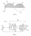
- FIG. 4 illustrates an example waveform which we have found to be advantageous in ultrasonic non-destructive testing.
- the waveform 44 includes two pulses 46, 48 which are a generating pulse 46 and a damping pulse 48.
- the generating pulse 46 is a pulse of a high frequency carrier on which a generally sinusoidal amplitude envelope is imposed.
- the damping pulse 48 is also a pulse of the high frequency carrier, and also in a generally sinusoidal amplitude envelope.
- the purpose of the generating pulse 46 is to excite the transducer 20 to generate ultrasound in the workpiece 36.
- stimulating a transducer 20 with a sinusoidal pulse such as the pulse 46 can result in resonance effects within the transducer 20, which may cause the ultrasound vibrations in the workpiece 36 to be longer than the signal provided to the transducer 20.
- An example is indicated at 47.
- the purpose of the damping pulse 48 is to address this issue.
- the timing and phase of the damping pulse 48 can be chosen to cause the damping pulse 48 to damp any residual resonance within the transducer 20.
- FIG. 5 An alternative ultrasound generating system 100 is depicted schematically in Fig. 5 .
- the system 100 shares many features in common with the apparatus 10.
- the system 100 includes an ultrasonic transceiver 118, and a control system 120 including a pulse generation module 124 and a controller module 126.
- the ultrasonic transducer 118 comprises a piezoelectric transducer which is fixed in use to an item under test (not shown) using a fixing such as glue. If desired, the ultrasonic transducer might be deposited in situ on the surface of the item.
- the fixing selected depends primarily on the item and the conditions it is expected to experience in use, but needs to enable good transmission of ultrasound signals over the temperature range expected in use.
- the sensor may be covered with a backing to assist in transmitting the ultrasonic signal to the item, such as an epoxy resin backing, for example steel reinforced epoxy.
- the transducer 118 has a centre frequency of approximately 10MHz, although other frequencies are possible.
- the pulse generation module 124 is operable to generate a voltage pulse having a peak amplitude of approximately 10V.
- the pulse generation module includes a pulse generator 140, an amplifier 142 and a signal blocker 144 (if required).
- the pulse generator is operable to generate a voltage pulse of substantially 1V which has a repeatable shape.
- the pulse comprises a square wave which physically manifests itself as a sine wave with a frequency of substantially 10MHz
- the pulse generator 140 comprises a first programmable element such as a field programmable gate array (FPGA 1).
- FPGA 1 is operable to receive the reflected signal.
- the amplifier 142 is operable to amplify the shaped signal produced by the FPGA 1 to approximately a 10V pulse without altering the frequency or shape. If such a high voltage signal were received by the FPGA 1, then it would damage the FPGA 1. Therefore, when the amplifier is active the signal blocker 144, which in this example is a field-effect transistor (FET), is activated simultaneously to ensure that no portion of the 10V signal can be transmitted back towards the FPGA 1. As soon as the amplifier has transmitted the 10V pulse, the signal blocker 144 is deactivated to allow the reflected signal to be detected by the FPGA 1.
- FET field-effect transistor
- separate transducers may be used for generating ultrasound and for sensing echoes, as noted above in relation to Fig. 2 . If so, a natural block is created between the excitation energy and the sensing transducer, which may make the signal blocker 144 unnecessary.
- the controller module 126 includes a further programmable element 146 such as a second field programmable gate array (FPGA 2) and a processor 148, and a memory 149.
- the FPGA 2 is operable to collect temperature data from a temperature sensor 150, such as a thermocouple, arranged to measure the temperature of the item under test.
- the processor 148 is in signal communication with both programmable elements 140 and 146, and receives signal data from FPGA 1 and temperature data from FPGA 2. The processor uses the received signal data and temperature data to produce a dimensional measurement.
- system 100 performs the following two sets of operations substantially simultaneously under control of the processor.
- programmable element 140 generates a 1V pulse 50ns in duration.
- the signal blocker 144 is activated, and the amplifier 142 amplifies the 1 V pulse to 10V.
- the signal blocker is then deactivated.
- the 10V signal is transmitted to the ultrasonic transceiver 118 over a cable.
- the ultrasonic transceiver converts the signal to an ultrasonic pulse, and transmits the pulse into the item under test.
- a reflected ultrasonic pulse is subsequently received by the ultrasonic transceiver, converted to an electrical signal, and detected by the programmable element 140.
- Data identifying the received signal (and in particular a collection of discrete measurements which together are indicative of the shape of the received signal) is transmitted to the processor for analysis/storage, and in particular for generation of a time of flight value.
- the processor instructs the second programmable element 146 to collect temperature data from the temperature sensor 150.
- a measured temperature value (which consists of two measurements) is stored in memory until FPGA 1 has collected the received signal.
- the processor determines a time of flight which is calibrated using the temperature value. A temperature independent dimensional value is then calculated. That value is indicative of a dimension, such as the thickness of the item under test.
Landscapes
- Engineering & Computer Science (AREA)
- Physics & Mathematics (AREA)
- Radar, Positioning & Navigation (AREA)
- Remote Sensing (AREA)
- General Physics & Mathematics (AREA)
- Acoustics & Sound (AREA)
- Computer Networks & Wireless Communication (AREA)
- Health & Medical Sciences (AREA)
- Life Sciences & Earth Sciences (AREA)
- Chemical & Material Sciences (AREA)
- Analytical Chemistry (AREA)
- Biochemistry (AREA)
- General Health & Medical Sciences (AREA)
- Immunology (AREA)
- Pathology (AREA)
- Mechanical Engineering (AREA)
- Length Measuring Devices Characterised By Use Of Acoustic Means (AREA)
- Investigating Or Analyzing Materials By The Use Of Ultrasonic Waves (AREA)
- Ultra Sonic Daignosis Equipment (AREA)
Applications Claiming Priority (2)
| Application Number | Priority Date | Filing Date | Title |
|---|---|---|---|
| US201161430229P | 2011-01-06 | 2011-01-06 | |
| PCT/US2012/020043 WO2012094294A1 (en) | 2011-01-06 | 2012-01-03 | Improvements in or relating to ultrasound generating apparatus, and methods for generating ultrasound |
Publications (2)
| Publication Number | Publication Date |
|---|---|
| EP2661329A1 EP2661329A1 (en) | 2013-11-13 |
| EP2661329B1 true EP2661329B1 (en) | 2014-09-10 |
Family
ID=45558382
Family Applications (2)
| Application Number | Title | Priority Date | Filing Date |
|---|---|---|---|
| EP12702625.0A Active EP2649468B1 (en) | 2011-01-06 | 2012-01-03 | Ultrasonic measurement |
| EP12701779.6A Active EP2661329B1 (en) | 2011-01-06 | 2012-01-03 | Improvements in or relating to ultrasound generating apparatus, and methods for generating ultrasound |
Family Applications Before (1)
| Application Number | Title | Priority Date | Filing Date |
|---|---|---|---|
| EP12702625.0A Active EP2649468B1 (en) | 2011-01-06 | 2012-01-03 | Ultrasonic measurement |
Country Status (8)
| Country | Link |
|---|---|
| US (2) | US9341602B2 (enExample) |
| EP (2) | EP2649468B1 (enExample) |
| JP (2) | JP5993871B2 (enExample) |
| KR (2) | KR20130137203A (enExample) |
| CN (2) | CN103380386B (enExample) |
| CA (2) | CA2823923A1 (enExample) |
| DK (2) | DK2649468T3 (enExample) |
| WO (2) | WO2012094294A1 (enExample) |
Families Citing this family (34)
| Publication number | Priority date | Publication date | Assignee | Title |
|---|---|---|---|---|
| US8997550B2 (en) * | 2012-06-19 | 2015-04-07 | General Electric Company | Method and system for correcting for temperature variations in ultrasonic testing systems |
| GB2512835A (en) * | 2013-04-08 | 2014-10-15 | Permasense Ltd | Ultrasonic detection of a change in a surface of a wall |
| DE102014202021A1 (de) * | 2014-02-05 | 2015-08-06 | Mahle International Gmbh | Verfahren zur Messung einer Wandstärke bei Hohlventilen |
| US20150233786A1 (en) * | 2014-02-14 | 2015-08-20 | Caterpillar Inc. | Ultrasonic measurement device |
| US10520302B2 (en) * | 2015-10-02 | 2019-12-31 | Honeywell International Inc. | Monitoring thickness uniformity |
| KR101670336B1 (ko) * | 2015-10-07 | 2016-10-28 | 금오공과대학교 산학협력단 | 고주파 영상 초음파 시스템을 위한 파워 앰프 선형자 |
| CN105855230A (zh) * | 2016-04-07 | 2016-08-17 | 马宁 | 一种模具超声波清洗机声波发生器 |
| CN105973997A (zh) * | 2016-04-28 | 2016-09-28 | 长沙金码高科技实业有限公司 | 一种超声波收发器 |
| FR3051913B1 (fr) * | 2016-05-25 | 2020-12-11 | Electricite De France | Procede de detection par ultrasons de defauts dans un materiau |
| CN106385290B (zh) * | 2016-08-16 | 2019-07-09 | 北京小米移动软件有限公司 | 超声波校准方法及装置 |
| US10386336B2 (en) * | 2016-08-24 | 2019-08-20 | Imam Abdulrahman Bin Faisal University | Ultrasonic pulse velocity tester |
| US12162160B2 (en) | 2016-12-23 | 2024-12-10 | Gecko Robotics, Inc. | System, apparatus and method for improved location identification with prism |
| ES2901649T3 (es) | 2016-12-23 | 2022-03-23 | Gecko Robotics Inc | Robot de inspección |
| US11307063B2 (en) | 2016-12-23 | 2022-04-19 | Gtc Law Group Pc & Affiliates | Inspection robot for horizontal tube inspection having vertically positionable sensor carriage |
| WO2020185719A2 (en) | 2019-03-08 | 2020-09-17 | Gecko Robotics, Inc. | Inspection robot |
| US12358141B2 (en) | 2016-12-23 | 2025-07-15 | Gecko Robotics, Inc. | Systems, methods, and apparatus for providing interactive inspection map for inspection robot |
| US10371669B2 (en) | 2017-02-02 | 2019-08-06 | Caterpillar Inc. | Ultrasonic sensing wear life of ground engaging tools |
| CN107802283A (zh) * | 2017-10-31 | 2018-03-16 | 深圳市第二人民医院 | 用于甲状腺疾病检查的成像系统 |
| DE102018205048A1 (de) * | 2018-04-04 | 2019-10-10 | Robert Bosch Gmbh | Verfahren und Vorrichtung zur Funktionsüberwachung von Ultraschallsensoren |
| KR102645311B1 (ko) | 2018-08-13 | 2024-03-08 | 삼성디스플레이 주식회사 | 두께 측정 장치 및 이를 이용한 두께 측정 방법 |
| JP7276744B2 (ja) | 2019-02-26 | 2023-05-18 | 国立大学法人豊橋技術科学大学 | 超音波検査装置及び超音波検査方法 |
| CN110530978B (zh) * | 2019-08-27 | 2022-06-21 | 南昌航空大学 | 高温铸锻件持续检测电磁超声探头、探伤装置及探伤方法 |
| CN111721966A (zh) * | 2020-06-29 | 2020-09-29 | 北京奥特美克科技股份有限公司 | 基于时差法的流速测量方法、装置、设备及可读存储介质 |
| US20220061807A1 (en) * | 2020-08-26 | 2022-03-03 | University Of Southern California | Actively damped ultrasonic transducer |
| CN112684456B (zh) * | 2020-12-22 | 2024-05-17 | 安徽配隆天环保科技有限公司 | 一种无人机超声立体成像模型系统 |
| EP4326493A4 (en) | 2021-04-20 | 2025-03-12 | Gecko Robotics, Inc. | FLEXIBLE INSPECTION ROBOT |
| CA3173120A1 (en) | 2021-04-22 | 2022-10-22 | Chase David | Systems, methods, and apparatus for ultra-sonic inspection of a surface |
| KR102568815B1 (ko) * | 2021-10-12 | 2023-08-22 | 한국건설기술연구원 | 콘크리트 비파괴검사를 위한 초음파 tof 추정 자동화 장치 및 방법 |
| US12247952B2 (en) | 2021-10-21 | 2025-03-11 | Council Of Scientific And Industrial Research | Ultrasonic pulse velocity tester device with threshold error correction |
| KR102791941B1 (ko) * | 2022-03-29 | 2025-04-08 | 서울대학교산학협력단 | 박막 두께 측정장치 및 방법 |
| CN119585642A (zh) * | 2022-07-29 | 2025-03-07 | 株式会社村田制作所 | 物体感测装置 |
| CN115365098B (zh) * | 2022-08-02 | 2024-09-27 | 山东科技大学 | 一种cmut传感器的频率追踪电路 |
| CN116642442B (zh) * | 2023-05-27 | 2025-03-25 | 东北电力大学 | 一种多角度超声检测换热污垢厚度方法、系统及装置 |
| US20250068190A1 (en) * | 2023-08-21 | 2025-02-27 | Saudi Arabian Oil Company | Monitoring Corrosion and Flushing Corrosive Media from Dead Legs in Piping |
Family Cites Families (40)
| Publication number | Priority date | Publication date | Assignee | Title |
|---|---|---|---|---|
| US3485087A (en) * | 1965-10-05 | 1969-12-23 | Branson Instr | Ultrasonic inspection apparatus |
| US3636778A (en) * | 1970-06-05 | 1972-01-25 | Atomic Energy Commission | Method and means for dimensional inspection of tubing |
| JPS57136107A (en) * | 1981-02-17 | 1982-08-23 | Teitsuu Denshi Kenkyusho:Kk | Ultrasonic thickness measuring method and apparatus |
| JPS58103440A (ja) * | 1981-07-31 | 1983-06-20 | オリンパス光学工業株式会社 | 超音波診断装置 |
| JPS61104276A (ja) * | 1984-10-29 | 1986-05-22 | Tokyo Keiki Co Ltd | 超音波パルスの送受信装置 |
| JPS61215908A (ja) * | 1985-02-20 | 1986-09-25 | Shimadzu Corp | 配管検査装置 |
| JPS6246282A (ja) | 1985-08-24 | 1987-02-28 | Matsushita Electric Ind Co Ltd | 超音波計測装置 |
| JPS6375512A (ja) * | 1986-09-18 | 1988-04-05 | Nippon Kurauto Kureemaa Fuerusutaa Kk | 超音波厚さ計 |
| US4711120A (en) * | 1986-10-06 | 1987-12-08 | Association Of American Railroads | Method of wear monitoring using ultrasonic phase comparison |
| JP2943567B2 (ja) * | 1993-07-14 | 1999-08-30 | 日本鋼管株式会社 | 管内形状検査装置 |
| DE4400210A1 (de) * | 1994-01-05 | 1995-08-10 | Branson Ultraschall | Verfahren und Einrichtung zum Betrieb eines Generators zur HF-Energieversorgung eines Ultraschallwandlers |
| CN1052791C (zh) * | 1994-01-28 | 2000-05-24 | 北京市市政工程研究院 | 在超声波检测分析仪上实现声时自动判读的方法 |
| JP3929508B2 (ja) * | 1994-04-21 | 2007-06-13 | 株式会社日立メディコ | 超音波断層装置 |
| US5577230A (en) * | 1994-08-10 | 1996-11-19 | At&T Corp. | Apparatus and method for computer processing using an enhanced Harvard architecture utilizing dual memory buses and the arbitration for data/instruction fetch |
| JP3379386B2 (ja) * | 1996-12-05 | 2003-02-24 | 住友金属工業株式会社 | 耐火物の損耗評価方法及びその装置、並びに耐火物の管理方法及びその装置 |
| JP2000005180A (ja) * | 1998-06-25 | 2000-01-11 | Olympus Optical Co Ltd | 音響インピーダンス測定装置 |
| JP3658504B2 (ja) * | 1998-07-09 | 2005-06-08 | 株式会社日立製作所 | 表面層厚さ測定装置 |
| GB0021114D0 (en) | 2000-08-29 | 2000-10-11 | Univ Sheffield | Method and apparatus for determining thickness of lubricant film |
| JP2002286441A (ja) * | 2001-03-28 | 2002-10-03 | Babcock Hitachi Kk | 厚さ測定装置 |
| JP2004535882A (ja) * | 2001-07-24 | 2004-12-02 | サンライト メディカル リミテッド | 超音波を用いた骨年齢評価方法 |
| JP4192490B2 (ja) * | 2002-04-26 | 2008-12-10 | 株式会社日立メディコ | 超音波診断装置 |
| JP2004053266A (ja) * | 2002-07-16 | 2004-02-19 | Fujimitsu Komuten:Kk | コンクリート構造物の版厚測定方法及び版厚測定システム |
| JP3913144B2 (ja) * | 2002-08-27 | 2007-05-09 | 株式会社日立製作所 | 配管検査方法及び装置 |
| US6897628B2 (en) * | 2003-05-16 | 2005-05-24 | Sulphco, Inc. | High-power ultrasound generator and use in chemical reactions |
| GB0414705D0 (en) | 2004-07-01 | 2004-08-04 | Univ Paisley The | Improvements to ultrasound transducers |
| TWI282779B (en) * | 2004-07-14 | 2007-06-21 | Asia Optical Co Inc | Molding core for molding glass |
| CN101040190B (zh) * | 2004-10-11 | 2012-02-29 | Nxp股份有限公司 | 非线性频率和相位测量方案 |
| JP4742675B2 (ja) * | 2005-05-20 | 2011-08-10 | 三菱化学株式会社 | 筒状体内面付着層の厚さ測定方法 |
| US20070068605A1 (en) | 2005-09-23 | 2007-03-29 | U.I.T., Llc | Method of metal performance improvement and protection against degradation and suppression thereof by ultrasonic impact |
| CN100408248C (zh) * | 2005-10-24 | 2008-08-06 | 中国电子科技集团公司第四十五研究所 | 自适应超声波换能器驱动电源 |
| DE102005060582A1 (de) * | 2005-12-17 | 2007-07-05 | Ndt Systems & Services Ag | Verfahren und System zur zerstörungsfreien Prüfung eines metallischen Werkstücks |
| CN101187650B (zh) * | 2006-01-12 | 2010-07-07 | 大连理工大学 | 一种离心球铁管球化率和壁厚的超声无损检测方法 |
| US7246522B1 (en) | 2006-02-24 | 2007-07-24 | Battelle Memorial Institute | Methods and apparatus for multi-parameter acoustic signature inspection |
| CN201012353Y (zh) * | 2007-03-22 | 2008-01-30 | 深圳市艾柯森自动化设备有限公司 | 数字式超声波发生器 |
| US7391242B1 (en) * | 2007-04-07 | 2008-06-24 | Ball Newton E | Sawtooth waveform generator |
| US8679019B2 (en) * | 2007-12-03 | 2014-03-25 | Bone Index Finland Oy | Method for measuring of thicknesses of materials using an ultrasound technique |
| CN201145594Y (zh) * | 2007-12-18 | 2008-11-05 | 深圳职业技术学院 | 一种超声波流量检测装置 |
| US7977820B2 (en) | 2008-02-14 | 2011-07-12 | Supertex, Inc. | Ultrasound transmit pulse generator |
| US8317706B2 (en) * | 2009-06-29 | 2012-11-27 | White Eagle Sonic Technologies, Inc. | Post-beamforming compression in ultrasound systems |
| CN102122166B (zh) * | 2011-03-29 | 2013-07-03 | 江洪 | 智能家居系统及其工作方法 |
-
2012
- 2012-01-03 EP EP12702625.0A patent/EP2649468B1/en active Active
- 2012-01-03 EP EP12701779.6A patent/EP2661329B1/en active Active
- 2012-01-03 DK DK12702625.0T patent/DK2649468T3/da active
- 2012-01-03 US US13/977,779 patent/US9341602B2/en active Active
- 2012-01-03 CA CA2823923A patent/CA2823923A1/en not_active Abandoned
- 2012-01-03 US US13/977,986 patent/US9335305B2/en active Active
- 2012-01-03 CA CA2823926A patent/CA2823926A1/en not_active Abandoned
- 2012-01-03 JP JP2013548456A patent/JP5993871B2/ja not_active Expired - Fee Related
- 2012-01-03 WO PCT/US2012/020043 patent/WO2012094294A1/en not_active Ceased
- 2012-01-03 KR KR1020137020359A patent/KR20130137203A/ko not_active Withdrawn
- 2012-01-03 WO PCT/US2012/020047 patent/WO2012094298A1/en not_active Ceased
- 2012-01-03 DK DK12701779.6T patent/DK2661329T3/da active
- 2012-01-03 KR KR1020137020795A patent/KR20140040692A/ko not_active Withdrawn
- 2012-01-03 JP JP2013548458A patent/JP5792321B2/ja not_active Expired - Fee Related
- 2012-01-03 CN CN201280009369.8A patent/CN103380386B/zh active Active
- 2012-01-03 CN CN201280007223.XA patent/CN103384571B/zh active Active
Also Published As
| Publication number | Publication date |
|---|---|
| JP2014503072A (ja) | 2014-02-06 |
| CA2823926A1 (en) | 2012-07-12 |
| US20140020468A1 (en) | 2014-01-23 |
| US20140224023A1 (en) | 2014-08-14 |
| JP5993871B2 (ja) | 2016-09-14 |
| WO2012094298A1 (en) | 2012-07-12 |
| EP2649468A1 (en) | 2013-10-16 |
| JP2014507643A (ja) | 2014-03-27 |
| EP2661329A1 (en) | 2013-11-13 |
| US9335305B2 (en) | 2016-05-10 |
| EP2649468B1 (en) | 2014-09-10 |
| KR20140040692A (ko) | 2014-04-03 |
| CN103380386A (zh) | 2013-10-30 |
| KR20130137203A (ko) | 2013-12-16 |
| US9341602B2 (en) | 2016-05-17 |
| CN103384571A (zh) | 2013-11-06 |
| CN103384571B (zh) | 2016-03-30 |
| DK2661329T3 (da) | 2014-10-13 |
| JP5792321B2 (ja) | 2015-10-07 |
| CN103380386B (zh) | 2016-01-20 |
| CA2823923A1 (en) | 2012-07-12 |
| WO2012094294A1 (en) | 2012-07-12 |
| DK2649468T3 (da) | 2014-11-03 |
Similar Documents
| Publication | Publication Date | Title |
|---|---|---|
| EP2661329B1 (en) | Improvements in or relating to ultrasound generating apparatus, and methods for generating ultrasound | |
| De Marchi et al. | A signal processing approach to exploit chirp excitation in Lamb wave defect detection and localization procedures | |
| JP2014503072A5 (enExample) | ||
| CN101576537A (zh) | 超声相控阵激励装置 | |
| Feeney et al. | High-frequency measurement of ultrasound using flexural ultrasonic transducers | |
| JPH08334431A (ja) | 非破壊検査装置 | |
| US5569854A (en) | Apparatus and method for transmitting and receiving ultrasonic waves having an acoustoelectric, ultrasonic transducer | |
| Yan et al. | A self-calibrating piezoelectric transducer with integral sensor for in situ energy calibration of acoustic emission | |
| JP4795925B2 (ja) | 超音波厚さ測定方法および装置 | |
| EP3469351B1 (en) | Method and device for compensating for coupling nonuniformities in ultrasonic testing | |
| CN110161126B (zh) | 适用于宽温域的固体应力波幅值衰减系数测试装置及方法 | |
| CN210427468U (zh) | 适用于宽温域的固体应力波幅值衰减系数测试装置 | |
| Yan et al. | A conical piezoelectric transducer with integral sensor as a self-calibrating acoustic emission energy source | |
| JP2018021809A (ja) | 超音波変位計測装置及び超音波変位計測方法 | |
| Lan et al. | Surface-to-surface calibration of acoustic emission sensors | |
| CN112526600B (zh) | 一种扫频超声波激发信号的振幅补偿方法及系统 | |
| US12265185B2 (en) | Variable resonance frequency acoustic wave emission and/or detection device | |
| Jian et al. | Miniature wideband ultrasonic transducers to measure compression and shear waves in solid | |
| WO2018015722A1 (en) | Non-destructive testing apparatus | |
| Vechera et al. | Study of the efficiency of the ultrasonic piezoelectric transducer of an echoscope depending on the geometric shape of the damper | |
| SU842567A1 (ru) | Ультразвуковой способ контрол КАчЕСТВА МНОгОСлОйНыХ издЕлий | |
| RU2554320C1 (ru) | Способ относительной калибровки преобразователей акустической эмиссии | |
| Juhrig et al. | A multichannel ultrasound pulser with arbitrary signal excitation unit for scanning acoustic microscopy | |
| RU2530450C1 (ru) | Способ измерения толщины изделия с помощью ультразвуковых импульсов | |
| Liang et al. | Design and Test of Capacitive Micro-machined Ultrasonic Transducer Array for the Air-coupled Ultrasound Imaging Applications |
Legal Events
| Date | Code | Title | Description |
|---|---|---|---|
| PUAI | Public reference made under article 153(3) epc to a published international application that has entered the european phase |
Free format text: ORIGINAL CODE: 0009012 |
|
| 17P | Request for examination filed |
Effective date: 20130712 |
|
| AK | Designated contracting states |
Kind code of ref document: A1 Designated state(s): AL AT BE BG CH CY CZ DE DK EE ES FI FR GB GR HR HU IE IS IT LI LT LU LV MC MK MT NL NO PL PT RO RS SE SI SK SM TR |
|
| DAX | Request for extension of the european patent (deleted) | ||
| GRAP | Despatch of communication of intention to grant a patent |
Free format text: ORIGINAL CODE: EPIDOSNIGR1 |
|
| INTG | Intention to grant announced |
Effective date: 20140509 |
|
| GRAS | Grant fee paid |
Free format text: ORIGINAL CODE: EPIDOSNIGR3 |
|
| GRAA | (expected) grant |
Free format text: ORIGINAL CODE: 0009210 |
|
| AK | Designated contracting states |
Kind code of ref document: B1 Designated state(s): AL AT BE BG CH CY CZ DE DK EE ES FI FR GB GR HR HU IE IS IT LI LT LU LV MC MK MT NL NO PL PT RO RS SE SI SK SM TR |
|
| REG | Reference to a national code |
Ref country code: GB Ref legal event code: FG4D |
|
| REG | Reference to a national code |
Ref country code: CH Ref legal event code: EP |
|
| REG | Reference to a national code |
Ref country code: IE Ref legal event code: FG4D |
|
| REG | Reference to a national code |
Ref country code: DK Ref legal event code: T3 Effective date: 20141006 |
|
| REG | Reference to a national code |
Ref country code: AT Ref legal event code: REF Ref document number: 686381 Country of ref document: AT Kind code of ref document: T Effective date: 20141015 |
|
| REG | Reference to a national code |
Ref country code: DE Ref legal event code: R096 Ref document number: 602012003072 Country of ref document: DE Effective date: 20141016 |
|
| REG | Reference to a national code |
Ref country code: SE Ref legal event code: TRGR |
|
| PG25 | Lapsed in a contracting state [announced via postgrant information from national office to epo] |
Ref country code: NO Free format text: LAPSE BECAUSE OF FAILURE TO SUBMIT A TRANSLATION OF THE DESCRIPTION OR TO PAY THE FEE WITHIN THE PRESCRIBED TIME-LIMIT Effective date: 20141210 Ref country code: LT Free format text: LAPSE BECAUSE OF FAILURE TO SUBMIT A TRANSLATION OF THE DESCRIPTION OR TO PAY THE FEE WITHIN THE PRESCRIBED TIME-LIMIT Effective date: 20140910 Ref country code: ES Free format text: LAPSE BECAUSE OF FAILURE TO SUBMIT A TRANSLATION OF THE DESCRIPTION OR TO PAY THE FEE WITHIN THE PRESCRIBED TIME-LIMIT Effective date: 20140910 Ref country code: GR Free format text: LAPSE BECAUSE OF FAILURE TO SUBMIT A TRANSLATION OF THE DESCRIPTION OR TO PAY THE FEE WITHIN THE PRESCRIBED TIME-LIMIT Effective date: 20141211 Ref country code: FI Free format text: LAPSE BECAUSE OF FAILURE TO SUBMIT A TRANSLATION OF THE DESCRIPTION OR TO PAY THE FEE WITHIN THE PRESCRIBED TIME-LIMIT Effective date: 20140910 |
|
| REG | Reference to a national code |
Ref country code: NL Ref legal event code: VDEP Effective date: 20140910 |
|
| REG | Reference to a national code |
Ref country code: LT Ref legal event code: MG4D |
|
| PG25 | Lapsed in a contracting state [announced via postgrant information from national office to epo] |
Ref country code: RS Free format text: LAPSE BECAUSE OF FAILURE TO SUBMIT A TRANSLATION OF THE DESCRIPTION OR TO PAY THE FEE WITHIN THE PRESCRIBED TIME-LIMIT Effective date: 20140910 Ref country code: CY Free format text: LAPSE BECAUSE OF FAILURE TO SUBMIT A TRANSLATION OF THE DESCRIPTION OR TO PAY THE FEE WITHIN THE PRESCRIBED TIME-LIMIT Effective date: 20140910 Ref country code: LV Free format text: LAPSE BECAUSE OF FAILURE TO SUBMIT A TRANSLATION OF THE DESCRIPTION OR TO PAY THE FEE WITHIN THE PRESCRIBED TIME-LIMIT Effective date: 20140910 Ref country code: HR Free format text: LAPSE BECAUSE OF FAILURE TO SUBMIT A TRANSLATION OF THE DESCRIPTION OR TO PAY THE FEE WITHIN THE PRESCRIBED TIME-LIMIT Effective date: 20140910 |
|
| REG | Reference to a national code |
Ref country code: AT Ref legal event code: MK05 Ref document number: 686381 Country of ref document: AT Kind code of ref document: T Effective date: 20140910 |
|
| PG25 | Lapsed in a contracting state [announced via postgrant information from national office to epo] |
Ref country code: NL Free format text: LAPSE BECAUSE OF FAILURE TO SUBMIT A TRANSLATION OF THE DESCRIPTION OR TO PAY THE FEE WITHIN THE PRESCRIBED TIME-LIMIT Effective date: 20140910 |
|
| PG25 | Lapsed in a contracting state [announced via postgrant information from national office to epo] |
Ref country code: RO Free format text: LAPSE BECAUSE OF FAILURE TO SUBMIT A TRANSLATION OF THE DESCRIPTION OR TO PAY THE FEE WITHIN THE PRESCRIBED TIME-LIMIT Effective date: 20140910 Ref country code: PT Free format text: LAPSE BECAUSE OF FAILURE TO SUBMIT A TRANSLATION OF THE DESCRIPTION OR TO PAY THE FEE WITHIN THE PRESCRIBED TIME-LIMIT Effective date: 20150112 Ref country code: EE Free format text: LAPSE BECAUSE OF FAILURE TO SUBMIT A TRANSLATION OF THE DESCRIPTION OR TO PAY THE FEE WITHIN THE PRESCRIBED TIME-LIMIT Effective date: 20140910 Ref country code: IS Free format text: LAPSE BECAUSE OF FAILURE TO SUBMIT A TRANSLATION OF THE DESCRIPTION OR TO PAY THE FEE WITHIN THE PRESCRIBED TIME-LIMIT Effective date: 20150110 Ref country code: SK Free format text: LAPSE BECAUSE OF FAILURE TO SUBMIT A TRANSLATION OF THE DESCRIPTION OR TO PAY THE FEE WITHIN THE PRESCRIBED TIME-LIMIT Effective date: 20140910 Ref country code: CZ Free format text: LAPSE BECAUSE OF FAILURE TO SUBMIT A TRANSLATION OF THE DESCRIPTION OR TO PAY THE FEE WITHIN THE PRESCRIBED TIME-LIMIT Effective date: 20140910 |
|
| PG25 | Lapsed in a contracting state [announced via postgrant information from national office to epo] |
Ref country code: PL Free format text: LAPSE BECAUSE OF FAILURE TO SUBMIT A TRANSLATION OF THE DESCRIPTION OR TO PAY THE FEE WITHIN THE PRESCRIBED TIME-LIMIT Effective date: 20140910 Ref country code: AT Free format text: LAPSE BECAUSE OF FAILURE TO SUBMIT A TRANSLATION OF THE DESCRIPTION OR TO PAY THE FEE WITHIN THE PRESCRIBED TIME-LIMIT Effective date: 20140910 |
|
| REG | Reference to a national code |
Ref country code: DE Ref legal event code: R097 Ref document number: 602012003072 Country of ref document: DE |
|
| PG25 | Lapsed in a contracting state [announced via postgrant information from national office to epo] |
Ref country code: BE Free format text: LAPSE BECAUSE OF NON-PAYMENT OF DUE FEES Effective date: 20150131 |
|
| PLBE | No opposition filed within time limit |
Free format text: ORIGINAL CODE: 0009261 |
|
| STAA | Information on the status of an ep patent application or granted ep patent |
Free format text: STATUS: NO OPPOSITION FILED WITHIN TIME LIMIT |
|
| 26N | No opposition filed |
Effective date: 20150611 |
|
| REG | Reference to a national code |
Ref country code: CH Ref legal event code: PL |
|
| PG25 | Lapsed in a contracting state [announced via postgrant information from national office to epo] |
Ref country code: LU Free format text: LAPSE BECAUSE OF FAILURE TO SUBMIT A TRANSLATION OF THE DESCRIPTION OR TO PAY THE FEE WITHIN THE PRESCRIBED TIME-LIMIT Effective date: 20150103 |
|
| PG25 | Lapsed in a contracting state [announced via postgrant information from national office to epo] |
Ref country code: MC Free format text: LAPSE BECAUSE OF FAILURE TO SUBMIT A TRANSLATION OF THE DESCRIPTION OR TO PAY THE FEE WITHIN THE PRESCRIBED TIME-LIMIT Effective date: 20140910 |
|
| PG25 | Lapsed in a contracting state [announced via postgrant information from national office to epo] |
Ref country code: LI Free format text: LAPSE BECAUSE OF NON-PAYMENT OF DUE FEES Effective date: 20150131 Ref country code: CH Free format text: LAPSE BECAUSE OF NON-PAYMENT OF DUE FEES Effective date: 20150131 |
|
| REG | Reference to a national code |
Ref country code: IE Ref legal event code: MM4A |
|
| PG25 | Lapsed in a contracting state [announced via postgrant information from national office to epo] |
Ref country code: SI Free format text: LAPSE BECAUSE OF FAILURE TO SUBMIT A TRANSLATION OF THE DESCRIPTION OR TO PAY THE FEE WITHIN THE PRESCRIBED TIME-LIMIT Effective date: 20140910 |
|
| REG | Reference to a national code |
Ref country code: FR Ref legal event code: PLFP Year of fee payment: 5 |
|
| PG25 | Lapsed in a contracting state [announced via postgrant information from national office to epo] |
Ref country code: IE Free format text: LAPSE BECAUSE OF NON-PAYMENT OF DUE FEES Effective date: 20150103 |
|
| PG25 | Lapsed in a contracting state [announced via postgrant information from national office to epo] |
Ref country code: BE Free format text: LAPSE BECAUSE OF FAILURE TO SUBMIT A TRANSLATION OF THE DESCRIPTION OR TO PAY THE FEE WITHIN THE PRESCRIBED TIME-LIMIT Effective date: 20140910 |
|
| PG25 | Lapsed in a contracting state [announced via postgrant information from national office to epo] |
Ref country code: MT Free format text: LAPSE BECAUSE OF FAILURE TO SUBMIT A TRANSLATION OF THE DESCRIPTION OR TO PAY THE FEE WITHIN THE PRESCRIBED TIME-LIMIT Effective date: 20140910 |
|
| REG | Reference to a national code |
Ref country code: FR Ref legal event code: PLFP Year of fee payment: 6 |
|
| PG25 | Lapsed in a contracting state [announced via postgrant information from national office to epo] |
Ref country code: SM Free format text: LAPSE BECAUSE OF FAILURE TO SUBMIT A TRANSLATION OF THE DESCRIPTION OR TO PAY THE FEE WITHIN THE PRESCRIBED TIME-LIMIT Effective date: 20140910 Ref country code: HU Free format text: LAPSE BECAUSE OF FAILURE TO SUBMIT A TRANSLATION OF THE DESCRIPTION OR TO PAY THE FEE WITHIN THE PRESCRIBED TIME-LIMIT; INVALID AB INITIO Effective date: 20120103 Ref country code: BG Free format text: LAPSE BECAUSE OF FAILURE TO SUBMIT A TRANSLATION OF THE DESCRIPTION OR TO PAY THE FEE WITHIN THE PRESCRIBED TIME-LIMIT Effective date: 20140910 |
|
| PGFP | Annual fee paid to national office [announced via postgrant information from national office to epo] |
Ref country code: DK Payment date: 20170125 Year of fee payment: 6 |
|
| PGFP | Annual fee paid to national office [announced via postgrant information from national office to epo] |
Ref country code: IT Payment date: 20170124 Year of fee payment: 6 |
|
| PG25 | Lapsed in a contracting state [announced via postgrant information from national office to epo] |
Ref country code: TR Free format text: LAPSE BECAUSE OF FAILURE TO SUBMIT A TRANSLATION OF THE DESCRIPTION OR TO PAY THE FEE WITHIN THE PRESCRIBED TIME-LIMIT Effective date: 20140910 |
|
| REG | Reference to a national code |
Ref country code: FR Ref legal event code: PLFP Year of fee payment: 7 |
|
| PG25 | Lapsed in a contracting state [announced via postgrant information from national office to epo] |
Ref country code: MK Free format text: LAPSE BECAUSE OF FAILURE TO SUBMIT A TRANSLATION OF THE DESCRIPTION OR TO PAY THE FEE WITHIN THE PRESCRIBED TIME-LIMIT Effective date: 20140910 |
|
| REG | Reference to a national code |
Ref country code: DK Ref legal event code: EBP Effective date: 20180131 |
|
| PG25 | Lapsed in a contracting state [announced via postgrant information from national office to epo] |
Ref country code: AL Free format text: LAPSE BECAUSE OF FAILURE TO SUBMIT A TRANSLATION OF THE DESCRIPTION OR TO PAY THE FEE WITHIN THE PRESCRIBED TIME-LIMIT Effective date: 20140910 |
|
| PG25 | Lapsed in a contracting state [announced via postgrant information from national office to epo] |
Ref country code: DK Free format text: LAPSE BECAUSE OF NON-PAYMENT OF DUE FEES Effective date: 20180131 |
|
| PG25 | Lapsed in a contracting state [announced via postgrant information from national office to epo] |
Ref country code: IT Free format text: LAPSE BECAUSE OF NON-PAYMENT OF DUE FEES Effective date: 20180103 |
|
| PGFP | Annual fee paid to national office [announced via postgrant information from national office to epo] |
Ref country code: SE Payment date: 20210127 Year of fee payment: 10 |
|
| REG | Reference to a national code |
Ref country code: SE Ref legal event code: EUG |
|
| PG25 | Lapsed in a contracting state [announced via postgrant information from national office to epo] |
Ref country code: SE Free format text: LAPSE BECAUSE OF NON-PAYMENT OF DUE FEES Effective date: 20220104 |
|
| P01 | Opt-out of the competence of the unified patent court (upc) registered |
Effective date: 20230523 |
|
| P02 | Opt-out of the competence of the unified patent court (upc) changed |
Effective date: 20230527 |
|
| PGFP | Annual fee paid to national office [announced via postgrant information from national office to epo] |
Ref country code: DE Payment date: 20250129 Year of fee payment: 14 |
|
| PGFP | Annual fee paid to national office [announced via postgrant information from national office to epo] |
Ref country code: FR Payment date: 20250127 Year of fee payment: 14 |
|
| PGFP | Annual fee paid to national office [announced via postgrant information from national office to epo] |
Ref country code: GB Payment date: 20250127 Year of fee payment: 14 |