EP2649468B1 - Ultrasonic measurement - Google Patents
Ultrasonic measurement Download PDFInfo
- Publication number
- EP2649468B1 EP2649468B1 EP12702625.0A EP12702625A EP2649468B1 EP 2649468 B1 EP2649468 B1 EP 2649468B1 EP 12702625 A EP12702625 A EP 12702625A EP 2649468 B1 EP2649468 B1 EP 2649468B1
- Authority
- EP
- European Patent Office
- Prior art keywords
- time
- ultrasonic
- flight
- item
- signal
- Prior art date
- Legal status (The legal status is an assumption and is not a legal conclusion. Google has not performed a legal analysis and makes no representation as to the accuracy of the status listed.)
- Active
Links
- 238000005259 measurement Methods 0.000 title claims description 49
- 238000000034 method Methods 0.000 claims description 54
- 239000002131 composite material Substances 0.000 claims description 41
- 239000000463 material Substances 0.000 claims description 24
- 230000000694 effects Effects 0.000 claims description 13
- 239000002184 metal Substances 0.000 claims description 8
- 229910052751 metal Inorganic materials 0.000 claims description 8
- PNEYBMLMFCGWSK-UHFFFAOYSA-N Alumina Chemical compound [O-2].[O-2].[O-2].[Al+3].[Al+3] PNEYBMLMFCGWSK-UHFFFAOYSA-N 0.000 claims description 6
- 229910000831 Steel Inorganic materials 0.000 claims description 4
- 239000004033 plastic Substances 0.000 claims description 4
- 229920003023 plastic Polymers 0.000 claims description 4
- 239000010959 steel Substances 0.000 claims description 4
- 229910045601 alloy Inorganic materials 0.000 claims description 3
- 239000000956 alloy Substances 0.000 claims description 3
- 239000005995 Aluminium silicate Substances 0.000 claims description 2
- 229910001369 Brass Inorganic materials 0.000 claims description 2
- RYGMFSIKBFXOCR-UHFFFAOYSA-N Copper Chemical compound [Cu] RYGMFSIKBFXOCR-UHFFFAOYSA-N 0.000 claims description 2
- ATJFFYVFTNAWJD-UHFFFAOYSA-N Tin Chemical compound [Sn] ATJFFYVFTNAWJD-UHFFFAOYSA-N 0.000 claims description 2
- 239000004411 aluminium Substances 0.000 claims description 2
- 229910052782 aluminium Inorganic materials 0.000 claims description 2
- XAGFODPZIPBFFR-UHFFFAOYSA-N aluminium Chemical compound [Al] XAGFODPZIPBFFR-UHFFFAOYSA-N 0.000 claims description 2
- 229910000323 aluminium silicate Inorganic materials 0.000 claims description 2
- 235000012211 aluminium silicate Nutrition 0.000 claims description 2
- 229910052797 bismuth Inorganic materials 0.000 claims description 2
- JCXGWMGPZLAOME-UHFFFAOYSA-N bismuth atom Chemical compound [Bi] JCXGWMGPZLAOME-UHFFFAOYSA-N 0.000 claims description 2
- 239000010951 brass Substances 0.000 claims description 2
- 239000000919 ceramic Substances 0.000 claims description 2
- 239000004567 concrete Substances 0.000 claims description 2
- 239000010949 copper Substances 0.000 claims description 2
- 229910052802 copper Inorganic materials 0.000 claims description 2
- 239000011133 lead Substances 0.000 claims description 2
- 150000002739 metals Chemical class 0.000 claims description 2
- 239000011135 tin Substances 0.000 claims description 2
- 229910052718 tin Inorganic materials 0.000 claims description 2
- YKTSYUJCYHOUJP-UHFFFAOYSA-N [O--].[Al+3].[Al+3].[O-][Si]([O-])([O-])[O-] Chemical compound [O--].[Al+3].[Al+3].[O-][Si]([O-])([O-])[O-] YKTSYUJCYHOUJP-UHFFFAOYSA-N 0.000 claims 1
- 238000000576 coating method Methods 0.000 claims 1
- -1 coatings Substances 0.000 claims 1
- 238000012360 testing method Methods 0.000 description 21
- 238000002604 ultrasonography Methods 0.000 description 13
- 230000008859 change Effects 0.000 description 11
- 239000000314 lubricant Substances 0.000 description 5
- 238000004458 analytical method Methods 0.000 description 4
- 238000013459 approach Methods 0.000 description 4
- 239000003990 capacitor Substances 0.000 description 4
- 238000004891 communication Methods 0.000 description 4
- 230000005284 excitation Effects 0.000 description 4
- 238000005070 sampling Methods 0.000 description 4
- 230000005540 biological transmission Effects 0.000 description 3
- 238000009529 body temperature measurement Methods 0.000 description 3
- 230000006870 function Effects 0.000 description 3
- 230000033001 locomotion Effects 0.000 description 3
- 239000002344 surface layer Substances 0.000 description 3
- 238000012935 Averaging Methods 0.000 description 2
- 230000004913 activation Effects 0.000 description 2
- 230000008602 contraction Effects 0.000 description 2
- 230000005669 field effect Effects 0.000 description 2
- 239000003292 glue Substances 0.000 description 2
- 238000011065 in-situ storage Methods 0.000 description 2
- 238000007689 inspection Methods 0.000 description 2
- 230000004044 response Effects 0.000 description 2
- 238000007619 statistical method Methods 0.000 description 2
- 238000003860 storage Methods 0.000 description 2
- 239000004593 Epoxy Substances 0.000 description 1
- 238000004026 adhesive bonding Methods 0.000 description 1
- PZZYQPZGQPZBDN-UHFFFAOYSA-N aluminium silicate Chemical compound O=[Al]O[Si](=O)O[Al]=O PZZYQPZGQPZBDN-UHFFFAOYSA-N 0.000 description 1
- 238000004364 calculation method Methods 0.000 description 1
- 239000000356 contaminant Substances 0.000 description 1
- 238000012937 correction Methods 0.000 description 1
- 239000013078 crystal Substances 0.000 description 1
- 238000007405 data analysis Methods 0.000 description 1
- 238000000151 deposition Methods 0.000 description 1
- 238000001514 detection method Methods 0.000 description 1
- 238000010586 diagram Methods 0.000 description 1
- 238000009826 distribution Methods 0.000 description 1
- 230000009977 dual effect Effects 0.000 description 1
- 239000003822 epoxy resin Substances 0.000 description 1
- 238000002474 experimental method Methods 0.000 description 1
- 239000012530 fluid Substances 0.000 description 1
- 230000003993 interaction Effects 0.000 description 1
- 230000001678 irradiating effect Effects 0.000 description 1
- 239000010410 layer Substances 0.000 description 1
- 239000007788 liquid Substances 0.000 description 1
- 238000012986 modification Methods 0.000 description 1
- 230000004048 modification Effects 0.000 description 1
- 229910052755 nonmetal Inorganic materials 0.000 description 1
- 229920000647 polyepoxide Polymers 0.000 description 1
- 238000002360 preparation method Methods 0.000 description 1
- 230000008569 process Effects 0.000 description 1
- 238000012545 processing Methods 0.000 description 1
- 230000005855 radiation Effects 0.000 description 1
- 230000002285 radioactive effect Effects 0.000 description 1
- 229920005989 resin Polymers 0.000 description 1
- 239000011347 resin Substances 0.000 description 1
- 239000007787 solid Substances 0.000 description 1
- 238000001228 spectrum Methods 0.000 description 1
- 230000001360 synchronised effect Effects 0.000 description 1
- 230000001960 triggered effect Effects 0.000 description 1
- 238000009683 ultrasonic thickness measurement Methods 0.000 description 1
Images


Classifications
-
- B—PERFORMING OPERATIONS; TRANSPORTING
- B06—GENERATING OR TRANSMITTING MECHANICAL VIBRATIONS IN GENERAL
- B06B—METHODS OR APPARATUS FOR GENERATING OR TRANSMITTING MECHANICAL VIBRATIONS OF INFRASONIC, SONIC, OR ULTRASONIC FREQUENCY, e.g. FOR PERFORMING MECHANICAL WORK IN GENERAL
- B06B1/00—Methods or apparatus for generating mechanical vibrations of infrasonic, sonic, or ultrasonic frequency
- B06B1/02—Methods or apparatus for generating mechanical vibrations of infrasonic, sonic, or ultrasonic frequency making use of electrical energy
- B06B1/0207—Driving circuits
-
- G—PHYSICS
- G01—MEASURING; TESTING
- G01N—INVESTIGATING OR ANALYSING MATERIALS BY DETERMINING THEIR CHEMICAL OR PHYSICAL PROPERTIES
- G01N29/00—Investigating or analysing materials by the use of ultrasonic, sonic or infrasonic waves; Visualisation of the interior of objects by transmitting ultrasonic or sonic waves through the object
- G01N29/34—Generating the ultrasonic, sonic or infrasonic waves, e.g. electronic circuits specially adapted therefor
- G01N29/346—Generating the ultrasonic, sonic or infrasonic waves, e.g. electronic circuits specially adapted therefor with amplitude characteristics, e.g. modulated signal
-
- G—PHYSICS
- G01—MEASURING; TESTING
- G01N—INVESTIGATING OR ANALYSING MATERIALS BY DETERMINING THEIR CHEMICAL OR PHYSICAL PROPERTIES
- G01N29/00—Investigating or analysing materials by the use of ultrasonic, sonic or infrasonic waves; Visualisation of the interior of objects by transmitting ultrasonic or sonic waves through the object
- G01N29/04—Analysing solids
- G01N29/07—Analysing solids by measuring propagation velocity or propagation time of acoustic waves
-
- G—PHYSICS
- G01—MEASURING; TESTING
- G01S—RADIO DIRECTION-FINDING; RADIO NAVIGATION; DETERMINING DISTANCE OR VELOCITY BY USE OF RADIO WAVES; LOCATING OR PRESENCE-DETECTING BY USE OF THE REFLECTION OR RERADIATION OF RADIO WAVES; ANALOGOUS ARRANGEMENTS USING OTHER WAVES
- G01S15/00—Systems using the reflection or reradiation of acoustic waves, e.g. sonar systems
- G01S15/88—Sonar systems specially adapted for specific applications
- G01S15/89—Sonar systems specially adapted for specific applications for mapping or imaging
-
- A—HUMAN NECESSITIES
- A61—MEDICAL OR VETERINARY SCIENCE; HYGIENE
- A61B—DIAGNOSIS; SURGERY; IDENTIFICATION
- A61B8/00—Diagnosis using ultrasonic, sonic or infrasonic waves
- A61B8/58—Testing, adjusting or calibrating the diagnostic device
Definitions
- the present invention relates to ultrasonic measurement, and particularly but not exclusively to apparatus and methods for ultrasonic measurement of dimension.
- an item that has regular contact with another item when in use might change in dimension over time, as it is worn away by the contact. Wear may also occur without contact, for example, through corrosive wear. Determining the effects of wear on an item can be important in calculating the expected life of the item, so that the item can be replaced before it fails or causes damage. Understanding the effects of wear is particularly important in machine components such as vehicle engine components or bearings. Determining the effects of wear can also be useful in testing the performance of an associated component, such as a lubricant.
- the first method of measuring wear requires analysing the surface of the item in question before and after it has been subjected to the effects of wear, for example using a coordinate measuring system. This method is not ideal, as it requires wear to already have occurred. It is also not possible to detect changes in the wear pattern whilst the wear is occurring over time.
- RNT radionucleotide testing
- SLA surface layer activation
- TLA thin layer activation
- This method includes irradiating the surface layer of an item. As wear occurs, irradiated metallic atoms are washed into lubricant, which is then circulated past a scintillation counter. The number of irradiated atoms detected is thus indicative of the rate of wear.
- This method is able to measure wear in close to real time, with only a short time lag due to the time taken for the metallic atoms to circulate. However, this method can only be used in controlled laboratory settings, due to the use of radiation. It is difficult to measure wear of multiple components simultaneously, due to the limited availability of radio isotopes, some of which have limited half lives. Furthermore, the measured wear rate often differs from the actual wear rate, as not all dislodged atoms are necessarily circulated.
- U.S. patent application US 2009/0143681 relates to a method for measuring thicknesses of materials of multi-layered structures.
- This method includes transmitting one or more ultrasound signals including different frequencies into a multi-layered structure consisting of two or more materials with one or more ultrasound transducers, measuring materials, acoustic properties for which are different at the frequencies in use, measuring ultrasound signals reflected from the front surface and back surface of the multi-layered structure with one or more ultrasound transducer and determining thicknesses of the materials within multi-layered structure from the reflected ultrasound signals.
- U.S. patent US 7246522 describes a multi-parameter acoustic signature inspection device and method for non-invasive inspection of containers. Dual acoustic signatures discriminate between various fluids and materials for identification of the same.
- Examples of the present invention provide a method of ultrasonic measurement, the method comprising the steps of:
- the single value might be a value for the dimension of the item.
- the single value might be a time of flight value.
- the item may comprise one or more of: metals, alloys, plastics, concrete, ceramics, coated materials and composite materials.
- the metal may be selected from steel, aluminium, copper, brass, tin, lead, bismuth, and alloys of the above.
- the item may comprise an aluminium oxide and/or an aluminium silicate.
- the method may include the step of determining a time of flight value from the information extracted from a respective received ultrasonic signal.
- a set comprising a plurality of time of flight values may be produced. Each time of flight value in the set may correspond to a respective received signal.
- Producing the value for dimension may comprise combining the plurality of time of flight values to produce a composite time of flight value, and may comprise using the composite time of flight value to determine the value for the dimension of the item.
- Producing the composite time of flight value may comprise performing a statistical operation, such as taking an average of the time of flight values, such as a mean, median or trimmed mean (typically the mean).
- Producing the composite time of flight value may comprise the step of producing a plurality of time of flight sub-values, and combining the time of flight sub-values to produce the composite time of flight value.
- Each time of flight sub-value may be produced from a sub-set of the time of flight values.
- Producing the value for dimension may comprise producing a composite time of flight value from the information extracted from the plurality of received signals, the composite time of flight value being indicative of an average time of flight, and may comprise using the composite time of flight value to determine the value for the dimension of the item.
- the transmitting and receiving steps may be repeated between 2 and 1,000,000 times over the specified period, which may be a second, or may be a fraction of a second, such as 0.2 seconds, or 0.5 seconds.
- the transmitting and receiving steps may be repeated between 2 and 450,000 times over the specified period, and may be repeated between 1000 and 100,000 times. Where the period is three seconds, the transmitting and receiving steps may be repeated 40,000 times. Where the period is 0.2 seconds the transmitting and receiving steps may be repeated 4005 times.
- the above ranges may be appropriate where the item comprises a metal.
- the number of transmitting and receiving steps may be the same, increased or reduced in dependence on the acoustic properties of the material. For example, the number of transmitting and receiving steps may be halved, or may be reduced to one third, one quarter, or one fifth of the above ranges.
- the method may further comprise the step of repeating the method at intervals to produce a plurality of composite dimensional values.
- the intervals may be regular intervals, for example the method may be repeated once a minute, or once every two minutes, ten minutes, hour, etc.
- the method may be employed wherein the item which is measured is subject to wear and said wear is evaluated by comparing the plurality of dimensional values.
- the step of determining the time of flight value may comprise identifying a time at which a zero amplitude of the reflected signal occurred.
- the zero amplitude may comprise an intercept zero, for example, a zero following a peak amplitude.
- the zero may comprise a first intercept zero.
- the receiving step may comprise receiving a first reflection of the transmitted signal.
- the receiving step may comprise receiving a higher order reflection, for example a second reflection, third reflection, or other multiple reflection.
- the method may further include the step of measuring one or more temperatures within an item.
- the temperatures may be measured over the specified period.
- the method may include the step of adjusting the composite dimensional value (if necessary) to calibrate the value with respect to temperature.
- Examples of the present invention provide an apparatus for determining a dimension of an item, wherein the apparatus is operable to perform the method of the first aspect of the invention.
- the apparatus may be operable to perform any combination of the method steps referred to above with respect to the first aspect of the invention, in any suitable order.
- the apparatus may comprise an ultrasonic transmitter operable to transmit an ultrasonic signal into an item and an ultrasonic receiver operable to receive an ultrasonic signal from an item.
- the ultrasonic transmitter and the ultrasonic receiver may together comprise an ultrasonic transceiver.
- the ultrasonic transceiver may be operable to produce either a broadband ultrasonic pulse, or an ultrasonic pulse having a frequency of between 1 and 100MHz, for example 2 to 50MHz, 3 to 50MHz, or 5 to 20 MHz.
- the ultrasonic transceiver may comprise a frequency of substantially 20MHz.
- the ultrasonic transceiver may comprise a frequency of substantially 10MHz.
- the ultrasonic transceiver may comprise a piezoelectric transducer.
- the apparatus may comprise a control system which is operable to supply an electrical signal to the ultrasonic transceiver to cause the ultrasonic transceiver to transmit the ultrasonic signal.
- the control system may be further operable to receive an electrical signal from the ultrasonic transceiver, the received electrical signal comprising information indicative of a dimension of the item.
- the control system may be operable to cause the ultrasonic transceiver to transmit a plurality of ultrasonic signals in a specified period, and may be operable to receive a plurality of electrical signals from the ultrasonic transceiver in the specified period.
- the control system may be operable to supply a voltage pulse to the ultrasonic transceiver.
- the control system may comprise a pulse generation module operable to supply the voltage pulse.
- the voltage pulse may be shaped, and may comprise a square wave, a triangle wave, or a sine wave, or part thereof.
- a wideband (multiple frequencies) wave can also be used to excite the transceiver.
- the wave may comprise a frequency of between 1 and 100MHz, for example 2 to 50MHz, 3 to 50MHz, or 5 to 20 MHz.
- the wave may comprise a frequency of substantially 20MHz.
- the wave may comprise a frequency of substantially 10MHz.
- the voltage pulse may have a peak amplitude of less than 200V, and may have a peak amplitude of between 2 and 100V, for example 5 and 20V.
- the voltage pulse may have a peak amplitude of approximately 10V.
- the pulse generation module may comprise a pulse generator operable to generate an initial voltage pulse and an amplifier operable to amplify the initial voltage pulse to produce an amplified pulse.
- the pulse generation module may further comprise a signal blocker which is operable to shield the pulse generator from the amplified pulse.
- the signal blocker may comprise a field-effect transistor. The signal blocker may be synchronised with the amplifier, such that the signal blocker is operable only when the amplifier is transmitting the amplified pulse, and is not operable otherwise.
- the ultrasonic transmitter and the ultrasonic receiver may be embodied separately to isolate the receiver from the excitation provided by the transmitter.
- the control system may be operable to extract from the received ultrasonic signals information indicative of a dimension of the item, and may be operable to use the information extracted from the plurality of received signals to determine a single value for the dimension of the item over the specified period.
- the control system may be operable to determine a time of flight value for a respective electrical signal, and to combine a plurality of such time of flight values to produce a composite time of flight value.
- the control system may use the composite time of flight value to produce the dimensional value.
- the apparatus may further include one or more temperature sensors, which may comprise one or more thermocouples.
- the control system may be operable to calibrate the value for dimension using a temperature measurement provided by the temperature sensor.
- an item comprising an apparatus in accordance with the second aspect of the invention.
- the item may be a machine such as a vehicle, or may be comprised within a machine such as a vehicle component (for example, an engine part).
- FIG. 1 an apparatus 10 for measuring a dimension of an item 12 using ultrasound is shown.
- Ultrasound refers to the portion of the sound frequency spectrum which is above human hearing, and typically is taken to include sounds having a frequency of greater than 20kHz. Ultrasound pulses pass through solid bodies at a speed determined by their material properties. Ultrasound pulses are typically reflected from interfaces or boundaries when a change in acoustic properties occurs.
- An ultrasonic signal which is reflected from a boundary includes information about that boundary.
- information about the distance to the boundary can be determined by measuring the time taken for an ultrasonic pulse transmitted into an item to pass through an item to the boundary and return as a reflection. It is possible (knowing the speed of sound in the material from which the item is made) to calculate the distance travelled by the reflected wave from this measured time. That distance is indicative of a dimension of the item, and in particular the distance to the boundary. Where the boundary is a surface, the dimension is indicative of the thickness of the item.
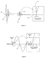
- FIG. 2A shows an ultrasonic transceiver 18 coupled to an item 12.
- the transceiver 18 When the transceiver 18 is excited by a suitable electrical pulse, the transceiver emits an ultrasonic signal i . That signal is transmitted through the item in a direction generally normal to the plane of the surface to which the transceiver is fixed. When the signal reaches a boundary, such as a test surface 28 of the item, at least a portion of the signal is reflected. The reflected signal r is detected at the ultrasonic transceiver 18 and converted to an electrical signal.
- a boundary such as a test surface 28 of the item
- Figure 2A also shows a graphical illustration 30 of the amplitude variations of the transmitted pulse i and the reflected pulse r over time.
- the reflected signal has a generally similar shape to the transmitted signal, but a reduced amplitude, as some signal energy is lost (due to attenuation, and because not all the signal will necessarily be reflected).
- the time 31 between the transmitted pulse and the received pulse is the signal's 'time of flight'. This time of flight 31 is indicative of the distance travelled by the signal, which distance is equal to twice the thickness of the item.
- Figure 2B illustrates a similar situation to Figure 2A , but with an item 112 which is thinner than the item 12 shown in Figure 2A .
- the item 112 is item 12 after it has experienced some wear. It will be seen that the time 31 between the outward i and reflected r pulses in Figure 2B is less that the equivalent time in Figure 2A , because the distance travelled is shorter.
- the term "uncertainty" means a single measurement (X) of thickness is a value such that, X ⁇ U forms a 95% confidence interval for the true, underlying, mean value of the thickness of the sample.
- X the standard deviation that would be obtained from a large sample of repeated thickness measurements of the same sample in a steady state (no wear occurring) at a constant temperature within a short period of time. It is assumed that the sampling procedure is such that the measurements are not autocorrelated. Then the uncertainty is defined as 1.96 s.
- the uncertainty is distinct from the repeatability of the method, as it deliberately does not take into account variation between runs, or due to sample preparation, but rather, is the uncertainty associated with a particular measurement at a particular time, due to short-term variation in the measurement.
- the uncertainty for a wear measurement is defined as 1 ⁇ 2 the width of a 95% confidence interval for the difference between measurements on the same sample before and after wear has occurred, and is equal to 1.96 ⁇ s ⁇ 2.
- the value of s used may be based on raw or temperature-adjusted thickness measurements as appropriate.
- the apparatus 10 shown in Figure 1 is operable to measure multiple values of the time of flight in quick succession over a specified period (such as 1 second). Those multiple values are statistically combined to produce a composite time of flight value which is used to determine a value for the dimension of the item in that specified period.
- the item under test 12 is in contact with a second item 14, and relative motion occurs between the two items, indicated in Figure 1 by arrow 16. Over time, the relative motion between the items 12 and 14 causes wear to both items.
- a lubricant such as an oil-based lubricant may be provided between the items to alter, and in particular reduce, the effects of wear.
- the apparatus 10 includes two main components, namely an ultrasonic transceiver 18 and a control system 20.
- the ultrasonic transceiver takes the form of a piezoelectric transducer which is able to both transmit an ultrasonic pulse into the item under test 12 and receive an ultrasonic pulse from the item 12.
- the ultrasonic transducer is physically coupled to the item 12, for example by gluing the transducer to a surface 22 of the item, or by depositing piezoelectric crystals forming transducer in situ on the item.
- the control system 20 is in communication with the ultrasonic transducer, and is operable to cause the ultrasonic transducer 18 to emit an ultrasonic signal.
- the control system 20 is also operable to interpret ultrasonic signals detected by the transducer.
- the control system 20 includes a pulse generation module 24 and a controller module 26.
- the pulse generation module 24 is operable to generate an electrical pulse to excite the ultrasonic transducer in response to an instruction from the controller module 26. When excited by an electrical pulse, the ultrasonic transducer is caused to emit an ultrasonic pulse.
- the pulse generation module 24 is further operable to receive an electrical signal generated by the ultrasonic transducer.
- the electrical signal is generated when an ultrasonic wave is incident with the ultrasonic transducer.
- the pulse generation module is operable to communicate a received electrical signal to the controller module for interpretation and analysis.
- the apparatus shown in Figure 1 implements the method set out in Figure 7 in order to determine a value for a dimension 11 of the item under test 12.
- an ultrasonic pulse is transmitted through the item 12 under test.
- the controller module causes pulse generation module to generate a voltage pulse, which in turn causes the ultrasonic transducer to generate an ultrasonic pulse.
- the ultrasonic pulse is transmitted into the item 12 because the ultrasonic transducer is coupled, and in this example permanently coupled, to the item.
- the transmitted ultrasonic pulse is subsequently reflected from a test surface 28 of the item, and the reflected pulse is received in step S2.
- the reflected pulse is received at the same location from which the original pulse was transmitted, and in particular at the ultrasonic transducer from which the pulse originated.
- the ultrasonic pulse is converted to an electrical signal by the ultrasonic transceiver, which is forwarded to the controller module for interpretation. Both the received ultrasonic pulse and the converted electrical signal contain information about the distance to the surface.
- a time of flight of the pulse is determined from the electrical signal.
- a single time of flight value can be determined to an uncertainty of ⁇ 1 ⁇ m, which is in general has too large an uncertainty for the purposes of quantifying wear.
- the time of flight value is determined by the control system, and in particular the controller module, and saved in memory.
- step S4 the steps S1 to S3 are repeated until a sufficient number of time of flight values have been collected.
- Sufficient refers to enough data points to represent the thickness of the item to a desired uncertainty based on the variability of the ultrasonic measurement. This number is normally predetermined, but does not necessarily need to be.
- the number of repetitions may be any natural number greater than 1 (e.g. two, ten, one hundred, one thousand, ten thousand, one million, etc). In general, the larger the number of values collected the greater the accuracy that is achieved.
- control system is operable to cause the steps S1 to S3 to repeat a predetermined number of times.
- the control system stores the plurality of time of flight values which are determined in memory, until its memory comprises a set of time of flight values equal in number to the predetermined value.
- step S5 the plurality of measured time of flight values are combined to produce a composite time of flight value.
- a normal distribution of the values is used to statistically combine the values to determine the mean value.
- the standard deviation from the mean may also be used to calculate the standard error of the mean.
- the composite time of flight value is used to produce a single dimensional value, which is indicative of the average distance travelled by each of the ultrasonic pulses over the period in which the plurality of measurements took place.
- the time period selected is short enough such that even in conditions of extreme wear the physical distance is unlikely to change significantly (such as less than 1 nm).
- the plurality of measurements might be made within the same second.
- Such a method and system can be used to measure a dimension of an item, such as its thickness, in real time.
- Multiple dimensional values can be produced if the method set out in Figure 7 is repeated at intervals, e.g. regular intervals such as once every 0.2 seconds, once a second, once a minute, or once every ten minutes.
- the plurality of dimensional values can be stored in memory of the controller module and/or transmitted to a remote location for storage and/or analysis, as appropriate, thus providing an accurate indication of the rate of wear over time, including changes in wear rate.
- the described system and method is robust, and can be used in the field as well as in a laboratory.
- the system can measure extreme changes in thickness, and is not limited to measuring wear of a thin radioactive surface layer.
- the system can be used with any material through which an ultrasonic pulse can be transmitted, such as metal, resin and plastics.
- any number of ultrasonic transducers might be provided in one system 10, or multiple systems 10 could be used in parallel, permitting multiple measurements to be taken simultaneously, on a plurality of different components if required.
- the transmitted ultrasound pulse has too low an amplitude, the reflected return signal may be difficult to detect over background noise, due to attenuation losses and the fact that not all the signal is necessarily reflected.
- a low amplitude transmitted pulse is particularly problematic if the system is used in a wet environment (e.g. where a liquid such as an oil or other lubricant is present on the test surface).
- a pulse generator After emission of a voltage pulse, a pulse generator typically experiences a period of 'relaxation' during which significant noise is generated. The higher the voltage pulse emitted the greater this amount noise, and the longer it takes to die away. If this relaxation period is too great, detection of the returning ultrasound pulse can be difficult, as the signal is likely to be lost in noise.
- the excitation voltage of the pulse generation module has therefore been selected taking these opposing considerations into account.
- a suitable voltage is less than 200V, for example in the range 1-100V, and in particular in the range 3-20V.
- the sample system described below uses a voltage of 10V.
- the voltage pulse generated (and hence the ultrasonic pulse) has a repeatable shape.
- Use of a repeatable pulse shape simplifies measuring time of flight repeatably, and also reduces the impact of noise on the composite time of flight value.
- the pulse generation is repeatable (or at least any variations in generation are predictable and minimised) the system can be more easily calibrated in relation to temperature (more detail below).
- a piezoelectric ultrasonic transducer can be excited by supplying a voltage pulse to the transducer.
- One way of generating such a voltage pulse is using a capacitor.
- Another way is using an operational amplifier. Both methods produce a reasonably repeatable pulse.
- the shape of the signal generated by an amplifier is typically more controllable than that generated by a capacitor, allowing generation of a specific shape of wave.
- using an amplifier enables generation of sine waves (for example by producing a voltage pulse shaped as a square wave, a triangular wave or a sine wave).
- Ultrasonic transducers are generally optimised to function most effectively at a specified frequency, and so producing an excitation pulse in the form of a sine wave at or near this frequency of operation can be more efficient.
- a third consideration in ultrasonic pulse generation relates to the frequency of the ultrasonic transceiver (and so the frequency of the ultrasonic pulse).
- lower frequency signals have better transmission characteristics (e.g. reduced attenuation).
- higher frequency signals are easier to analyse in a repeatable way (discussed in more detail below).
- a suitable frequency might be selected from the range 1-100MHz, and in particular the range 3-50MHz.
- the system described above uses a frequency of 10MHz, although frequencies of up to 30MHz, e.g. 20 MHz, have also been found to give good results.
- the time of flight of the reflected pulse can be measured by noting the time at which a predetermined feature on the reflected wave is received. This received time can be compared with the time at which the equivalent feature on the outgoing pulse was generated (which may either be measured or known) in order to determine the time of flight.
- time of flight is calculated by measuring the time between the peak amplitude of the transmitted signal and the peak amplitude of the return signal.
- interactions with the test surface can distort the shape of the reflected signal, resulting in movement of the peak of the measured reflected signal from its expected location as compared with a simulated reflected peak.
- This phenomenon is shown in Figure 3 , where at 34 the change in amplitude over time of a simulated or 'ideal' reflection is shown in broken lines, overlaid for comparison with a measured reflection in solid lines. It will be seen that the shape of the measured reflection is distorted with respect to the ideal signal, due to noise. In particular, the peak amplitude has changed, as has the time at which that peak occurs as measured on the x-axis.
- the distortions in the shape of the reflected peak are not necessarily consistent from one measurement to the next (for example, surface contaminants may disperse or increase over time).
- these amplitude variations can introduce perceived changes in time of flight which do not correspond to physical changes in dimension, resulting in inaccuracy.
- a logical approach might be to look for the leading edge of the reflected wave. If a capacitor bank has been used to generate the initial pulse, it is typical that there is a delay in reaching the zero amplitude following the pulse emission, and this can impinge on the first reflection. This effect makes resolution of the time at which the reflection occurred 37 (i.e. the time which is equivalent to the start time 35 of the transmitted pulse) difficult.
- Figure 3 illustrates how the start time 37 of the ideal (without noise) reflection can be obscured in detail 36. If the time of flight were measured to the apparent 'zero' 38 a time shift error is introduced. If an operational amplifier system is used, and there is no delay in reaching zero amplitude, there is still a problem in determining when the leading edge threshold value has been triggered. This is shown in Figure 4 , where the background noise of the signal makes identifying the zero amplitude point where the leading edge rises difficult.
- Another difficulty in measuring between the origin times of the two pulses is that, in data analysis, when identifying a wave, typically a threshold value is looked for rather than the actual zero point itself. Because the amplitude of a reflection can change from wave to wave, this method can introduce further error, as illustrated in Figure 4 . In particular, it takes longer for a reflection having a lower peak amplitude (shown in broken lines) to reach the threshold value than another reflection having a higher peak amplitude (shown in solid lines), introducing an apparent difference in time of flight between the two waves, where none in fact exists.
- An intercept zero 40 is one at which the wave re-crosses the amplitude axis (i.e. has zero amplitude but a time after the start time of the pulse).
- the intercept point 40 used in the system described herein is the first intercept zero, or 'second zero', but subsequent intercept points could be used if desired.
- the wave is essentially linear, such that the location of the point can be interpolated repeatably from measurements made before and after crossing the axis with the least disturbances from other noise.
- This point is essentially unaffected by changes in the amplitude of the wave, as shown in Figures 3 and 4 .
- the frequency selected for the signal needs to be balanced with other requirements of the system, particularly the depth of material through which the signal needs to be transmitted.
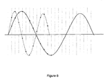
- Figure 8 illustrates two ultrasonic waves which have different frequencies, but are sampled at the same rate.
- the dotted line represents the higher frequency signal
- the solid line represents the lower frequency signal.
- samples' are aggregated and statistical operations performed on them to determine a composite value for the thickness of the material.
- the number of samples which can be taken is physically restricted, because of the necessity to wait until the first reflected signal has been received (and possibly further reflections have died away) before transmitting a second signal.
- a suitable sample set might include between 10,000 and 80,000 samples taken at regular intervals over a 1 second period.
- the example system described below is operable to collect a sample set of approximately 40,000 samples every three seconds.
- Calculating a mean (as opposed to median or mode) from a sample set of this size is computationally intensive.
- a set comprising information derived from a plurality of received signals is broken down into a plurality (and in particular ten) smaller sub-sets. Each sub-set is averaged to product a time of flight 'sub-value', and the resultant sub-values are then combined to produce the composite value.
- This two-stage statistical analysis can be completed more quickly and efficiently than simply producing an average of the complete set of individual measured time of flight values.
- sampling continuously for 1 second is not as accurate as taking multiple sample sets over a 1 second periods (e.g. producing a sample set every 0.2 seconds). This is because the effects of temperature change are likely to be smaller over a shorter time.
- Each sub-set might include a sample size with a range of 2-100,000 time of flight values, such as 2-45,000, 100-10,000 or 3000 to 5000.
- 4005 samples are taken in each sub-set. This number has been selected as the number of discrete samples which are taken in 0.2s. In theory a larger number of smaller sub-sets might allow a composite value to determined more quickly. However, it is difficult to synchronously link sub-sets spanning a time period shorter than 0.2s to temperature.
- ten sub-sets of 4005 are produced over ten consecutive 0.2s periods (which might be 0.1 seconds apart).
- a time of flight sub-value is produced for each sub-set.
- Those ten sub-values are then combined to produce a time of flight values for a three second period. That composite time of flight value includes data from approximately 40,000 individual measurements.
- An alternative approach to calculating a mean of each sub-set would be to interleave a sub-set of samples (e.g. up to 20 sequential samples might be interleaved) to generate a more accurate single wave. These interleaved waves could then be statistically combined as discussed above to produce the composite value.
- a change in temperature changes several properties of the measurement. These properties include amongst others:
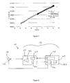
- Figure 5 shows the results of such a calibration.
- the data points were collected during an experiment where a specimen was heated and cooled but not subjected to wear. Each data point is the result of 4005 measurements of thickness captured in 0.2 seconds. The system was run at 100 collections per minute and the thickness plotted against temperature. From this point a linear relationship is assumed and an appropriate 'straight-line' function calculated (although other options are available, such as spline functions, look-up tables or polynomials). This relationship is then used to equate subsequent readings (e.g. during a wear test) to the original. For example, measured thickness might be calibrated back to a standard temperature.
- Temperature variations can significantly alter the measured thickness values. Therefore it can be desirable to acquire accurate temperature measurements substantially simultaneously with the ultrasonic thickness measurements, allowing the dimensional value to be calibrated.
- One way of obtaining accurate and repeatable temperature readings is using a thermocouple mounted on the surface of the item under test next to the ultrasonic sensor. It may also be useful to provide additional temperature reading from other locations, e.g. on a remote surface of the item (e.g. the surface which is subjected to wear) or at another depth in the item.
- An ultrasonic dimension measuring system 100 which takes into account the above considerations is depicted schematically in Figure 6 .
- the system 100 shares many features in common with the apparatus 10.
- the system 100 includes an ultrasonic transceiver 118, and a control system 120 including a pulse generation module 124 and a controller module 126.
- the ultrasonic transducer 118 comprises a piezoelectric transducer which is fixed in use to an item under test (not shown) using a fixing such as glue. If desired, the ultrasonic transducer might be deposited in situ on the surface of the item.
- the fixing selected depends primarily on the item and the conditions it is expected to experience in use, but needs to enable good transmission of ultrasound signals over the temperature range expected in use.
- the sensor may be covered with a backing to assist in transmitting the ultrasonic signal to the item, such as an epoxy resin backing, for example steel reinforced epoxy.
- the transducer 118 has a frequency of approximately 10MHz, although other frequencies are possible, as discussed above.
- the pulse generation module 124 is operable to generate a voltage pulse having a peak amplitude of approximately 10V.
- the pulse generation module includes a pulse generator 140, an amplifier 142 and a signal blocker 144.
- the pulse generator is operable to generate a voltage pulse of substantially 1V which has a repeatable shape.
- the pulse comprises a sine wave with a frequency of substantially 10MHz
- the pulse generator 140 comprises a first programmable element such as a field programmable gate array (FPGA 1).
- FPGA 1 is operable to receive the reflected signal.
- the amplifier 142 is operable to amplify the shaped signal produced by the FPGA 1 to approximately a 10V pulse without altering the frequency. If such a high voltage signal were received by the FPGA 1, then it would damage the FPGA 1. Therefore, when the amplifier is active the signal blocker 144, which in this example is a field-effect transistor (FET), is activated simultaneously to ensure that no portion of the 10V signal can be transmitted back towards the FPGA 1. As soon as the amplifier has transmitted the 10V pulse, the signal blocker 144 is deactivated to allow the reflected signal to be detected by the FPGA 1.
- FET field-effect transistor
- the controller module 126 includes a further programmable element 146 such as a second field programmable gate array (FPGA 2) and a processor 148, and a memory 149.
- the FPGA 2 is operable to collect temperature data from temperature sensors 150, such as thermocouples, arranged to measure the temperature of the item under test.
- the processor 148 is in signal communication with both programmable elements 140 and 146, and receives signal data from FPGA 1 and temperature data from FPGA 2. The processor uses the received signal data and temperature data to produce a dimensional measurement.
- system 100 performs the following two sets of operations substantially simultaneously under control of the processor.
- programmable element 140 generates a 1V pulse 50ns in duration.
- the signal blocker 144 is activated, and the amplifier 142 amplifies the 1V pulse to 10V.
- the signal blocker is then deactivated.
- the 10V signal is transmitted to the ultrasonic transceiver 118 over a cable.
- the ultrasonic transceiver converts the signal to an ultrasonic pulse, and transmits the pulse into the item under test.
- a reflected ultrasonic pulse is subsequently received by the ultrasonic transceiver, converted to an electrical signal, and detected by the programmable element 140.
- Data identifying the received signal (and in particular a collection of discrete measurements which together are indicative of the shape of the received signal) is transmitted to the processor for analysis/storage, and in particular for generation of a time of flight value.
- This set of operations is repeated a predetermined number of times in a specified time period, and in this example is repeated approximately 4005 times in 0.2s.
- the ultrasonic transceiver 118 may be replaced by an ultrasonic transmitter and an ultrasonic receiver embodied separately. This will help to isolate the receiver from the excitation provided by the transmitter, to render the signal blocker 144 unnecessary. This is indicated in Fig. 6 by a broken line through the transceiver 118 to indicate the use of a transmitter and a separate receiver.
- the processor instructs the second programmable element 146 to collect temperature data from the temperature sensor 150.
- a measured temperature value (which consists of two measurements) is stored in memory until FPGA 1 has collected the predetermined number of samples.
- the processor determines a time of flight for each measurement by locating the first intercept zero, as discussed above.
- the set of time of flight values are then averaged to produce a single time of flight value, which is calibrated using the temperature value.
- a temperature independent dimensional value is then calculated. That value is indicative of the thickness of the item under test in the 0.2s over which the measurement operations took place.
- the system is operable to repeat the above operations a predetermined number of times to produce further dimensional values, which can then be combined to produce a more accurate composite dimensional value averaged over a longer time period (e.g. 1s).
- the system is arranged to repeat the above operations ten times (for example at intervals of approximately 0.5 seconds), and to average the resulting ten dimensional values to produce a composite dimensional value for a 5 second period.
- the entire method can be repeated as many times as desired.
- the method might be repeated at regular intervals, for example every minute, or every ten minutes, to produce a plurality of composite dimensional values.
- a record of such composite dimensional values, and perhaps their respective times of measurement, may be stored (either in memory 149 or in another, possibly remote, location), to produce a record showing change in dimension (if any) over time.
- the above system and method can be used to measure dimension in a range of materials such as metal, plastics or composites, and the material properties and thickness will affect the signal quality being generated.
- the system is able to measure changes in dimension of items with initial dimensions ranging between 3-400mm or 3-300mm, more typically 3-100, or 3-30mm, depending on material properties.
- the system can operate under a range of conditions, and in particular is not limited to use in a laboratory.
- the system might be installed in a machine under test, which might be a vehicle such as an automotive vehicle or a nautical vessel, and used to produce real time measurements of dimension whilst the vehicle is in use.
- the system might include multiple ultrasonic transducers, allowing multiple components in the same vehicle to be measured simultaneously.
- each ultrasonic transducer would comprise a respective temperature sensing arrangement, but might share a single processor and single pulse generator.
- the control system might be in communication (for example wireless communication) with a remote control hub. Dimensional measurements, along with other measured data such as time and temperature data, might be transmitted to the control hub by the control system using a wireless transmission device. The data acquired by the system can thus be analysed in substantially real time from a remote location.
- first programmable element 140 might be comprised with a housing including the second programmable element 146, which might be separate from a housing including the amplifier and signal blocker.
- the processor 148 might be comprised in the same housing as the programmable element, or might be remote from the remainder of the system.
- the method steps might be conducted in any suitable order, and in particular that the step of statistically combining the signals might take place at any suitable stage of the method.
- the signal information is combined after time of flight values have been produced for each received signal.
- the time of flight data representing the received electrical signals might be combined prior to producing a composite time of flight value from that combined date.
- a plurality of individual dimensional values might be produced, one for each reflected signal, or sub-set of reflected signals. Those dimensional values might then be statistically combined to produce the composite dimensional value.
Landscapes
- Engineering & Computer Science (AREA)
- Physics & Mathematics (AREA)
- Remote Sensing (AREA)
- Radar, Positioning & Navigation (AREA)
- General Physics & Mathematics (AREA)
- Acoustics & Sound (AREA)
- Computer Networks & Wireless Communication (AREA)
- Analytical Chemistry (AREA)
- Immunology (AREA)
- Pathology (AREA)
- General Health & Medical Sciences (AREA)
- Biochemistry (AREA)
- Chemical & Material Sciences (AREA)
- Life Sciences & Earth Sciences (AREA)
- Health & Medical Sciences (AREA)
- Mechanical Engineering (AREA)
- Length Measuring Devices Characterised By Use Of Acoustic Means (AREA)
- Investigating Or Analyzing Materials By The Use Of Ultrasonic Waves (AREA)
- Ultra Sonic Daignosis Equipment (AREA)
Applications Claiming Priority (2)
| Application Number | Priority Date | Filing Date | Title |
|---|---|---|---|
| US201161430229P | 2011-01-06 | 2011-01-06 | |
| PCT/US2012/020047 WO2012094298A1 (en) | 2011-01-06 | 2012-01-03 | Ultrasonic measurement |
Publications (2)
| Publication Number | Publication Date |
|---|---|
| EP2649468A1 EP2649468A1 (en) | 2013-10-16 |
| EP2649468B1 true EP2649468B1 (en) | 2014-09-10 |
Family
ID=45558382
Family Applications (2)
| Application Number | Title | Priority Date | Filing Date |
|---|---|---|---|
| EP12702625.0A Active EP2649468B1 (en) | 2011-01-06 | 2012-01-03 | Ultrasonic measurement |
| EP12701779.6A Active EP2661329B1 (en) | 2011-01-06 | 2012-01-03 | Improvements in or relating to ultrasound generating apparatus, and methods for generating ultrasound |
Family Applications After (1)
| Application Number | Title | Priority Date | Filing Date |
|---|---|---|---|
| EP12701779.6A Active EP2661329B1 (en) | 2011-01-06 | 2012-01-03 | Improvements in or relating to ultrasound generating apparatus, and methods for generating ultrasound |
Country Status (8)
| Country | Link |
|---|---|
| US (2) | US9335305B2 (enExample) |
| EP (2) | EP2649468B1 (enExample) |
| JP (2) | JP5792321B2 (enExample) |
| KR (2) | KR20140040692A (enExample) |
| CN (2) | CN103380386B (enExample) |
| CA (2) | CA2823926A1 (enExample) |
| DK (2) | DK2649468T3 (enExample) |
| WO (2) | WO2012094298A1 (enExample) |
Families Citing this family (34)
| Publication number | Priority date | Publication date | Assignee | Title |
|---|---|---|---|---|
| US8997550B2 (en) * | 2012-06-19 | 2015-04-07 | General Electric Company | Method and system for correcting for temperature variations in ultrasonic testing systems |
| GB2512835A (en) * | 2013-04-08 | 2014-10-15 | Permasense Ltd | Ultrasonic detection of a change in a surface of a wall |
| DE102014202021A1 (de) * | 2014-02-05 | 2015-08-06 | Mahle International Gmbh | Verfahren zur Messung einer Wandstärke bei Hohlventilen |
| US20150233786A1 (en) * | 2014-02-14 | 2015-08-20 | Caterpillar Inc. | Ultrasonic measurement device |
| US10520302B2 (en) * | 2015-10-02 | 2019-12-31 | Honeywell International Inc. | Monitoring thickness uniformity |
| KR101670336B1 (ko) * | 2015-10-07 | 2016-10-28 | 금오공과대학교 산학협력단 | 고주파 영상 초음파 시스템을 위한 파워 앰프 선형자 |
| CN105855230A (zh) * | 2016-04-07 | 2016-08-17 | 马宁 | 一种模具超声波清洗机声波发生器 |
| CN105973997A (zh) * | 2016-04-28 | 2016-09-28 | 长沙金码高科技实业有限公司 | 一种超声波收发器 |
| FR3051913B1 (fr) * | 2016-05-25 | 2020-12-11 | Electricite De France | Procede de detection par ultrasons de defauts dans un materiau |
| CN106385290B (zh) * | 2016-08-16 | 2019-07-09 | 北京小米移动软件有限公司 | 超声波校准方法及装置 |
| US10386336B2 (en) * | 2016-08-24 | 2019-08-20 | Imam Abdulrahman Bin Faisal University | Ultrasonic pulse velocity tester |
| US11307063B2 (en) | 2016-12-23 | 2022-04-19 | Gtc Law Group Pc & Affiliates | Inspection robot for horizontal tube inspection having vertically positionable sensor carriage |
| US12358141B2 (en) | 2016-12-23 | 2025-07-15 | Gecko Robotics, Inc. | Systems, methods, and apparatus for providing interactive inspection map for inspection robot |
| US12162160B2 (en) | 2016-12-23 | 2024-12-10 | Gecko Robotics, Inc. | System, apparatus and method for improved location identification with prism |
| WO2018119450A1 (en) | 2016-12-23 | 2018-06-28 | Gecko Robotics, Inc. | Inspection robot |
| US10371669B2 (en) | 2017-02-02 | 2019-08-06 | Caterpillar Inc. | Ultrasonic sensing wear life of ground engaging tools |
| CN107802283A (zh) * | 2017-10-31 | 2018-03-16 | 深圳市第二人民医院 | 用于甲状腺疾病检查的成像系统 |
| DE102018205048A1 (de) * | 2018-04-04 | 2019-10-10 | Robert Bosch Gmbh | Verfahren und Vorrichtung zur Funktionsüberwachung von Ultraschallsensoren |
| KR102645311B1 (ko) | 2018-08-13 | 2024-03-08 | 삼성디스플레이 주식회사 | 두께 측정 장치 및 이를 이용한 두께 측정 방법 |
| JP7276744B2 (ja) | 2019-02-26 | 2023-05-18 | 国立大学法人豊橋技術科学大学 | 超音波検査装置及び超音波検査方法 |
| CA3126283A1 (en) | 2019-03-08 | 2020-09-17 | Gecko Robotics, Inc. | Inspection robot |
| CN110530978B (zh) * | 2019-08-27 | 2022-06-21 | 南昌航空大学 | 高温铸锻件持续检测电磁超声探头、探伤装置及探伤方法 |
| CN111721966A (zh) * | 2020-06-29 | 2020-09-29 | 北京奥特美克科技股份有限公司 | 基于时差法的流速测量方法、装置、设备及可读存储介质 |
| US20220061807A1 (en) * | 2020-08-26 | 2022-03-03 | University Of Southern California | Actively damped ultrasonic transducer |
| CN112684456B (zh) * | 2020-12-22 | 2024-05-17 | 安徽配隆天环保科技有限公司 | 一种无人机超声立体成像模型系统 |
| US11865698B2 (en) | 2021-04-20 | 2024-01-09 | Gecko Robotics, Inc. | Inspection robot with removeable interface plates and method for configuring payload interfaces |
| US11971389B2 (en) | 2021-04-22 | 2024-04-30 | Gecko Robotics, Inc. | Systems, methods, and apparatus for ultra-sonic inspection of a surface |
| KR102568815B1 (ko) * | 2021-10-12 | 2023-08-22 | 한국건설기술연구원 | 콘크리트 비파괴검사를 위한 초음파 tof 추정 자동화 장치 및 방법 |
| US12247952B2 (en) | 2021-10-21 | 2025-03-11 | Council Of Scientific And Industrial Research | Ultrasonic pulse velocity tester device with threshold error correction |
| KR102791941B1 (ko) * | 2022-03-29 | 2025-04-08 | 서울대학교산학협력단 | 박막 두께 측정장치 및 방법 |
| CN119585642A (zh) * | 2022-07-29 | 2025-03-07 | 株式会社村田制作所 | 物体感测装置 |
| CN115365098B (zh) * | 2022-08-02 | 2024-09-27 | 山东科技大学 | 一种cmut传感器的频率追踪电路 |
| CN116642442B (zh) * | 2023-05-27 | 2025-03-25 | 东北电力大学 | 一种多角度超声检测换热污垢厚度方法、系统及装置 |
| US20250068190A1 (en) * | 2023-08-21 | 2025-02-27 | Saudi Arabian Oil Company | Monitoring Corrosion and Flushing Corrosive Media from Dead Legs in Piping |
Family Cites Families (40)
| Publication number | Priority date | Publication date | Assignee | Title |
|---|---|---|---|---|
| US3485087A (en) * | 1965-10-05 | 1969-12-23 | Branson Instr | Ultrasonic inspection apparatus |
| US3636778A (en) * | 1970-06-05 | 1972-01-25 | Atomic Energy Commission | Method and means for dimensional inspection of tubing |
| JPS57136107A (en) * | 1981-02-17 | 1982-08-23 | Teitsuu Denshi Kenkyusho:Kk | Ultrasonic thickness measuring method and apparatus |
| JPS58103440A (ja) | 1981-07-31 | 1983-06-20 | オリンパス光学工業株式会社 | 超音波診断装置 |
| JPS61104276A (ja) * | 1984-10-29 | 1986-05-22 | Tokyo Keiki Co Ltd | 超音波パルスの送受信装置 |
| JPS61215908A (ja) * | 1985-02-20 | 1986-09-25 | Shimadzu Corp | 配管検査装置 |
| JPS6246282A (ja) * | 1985-08-24 | 1987-02-28 | Matsushita Electric Ind Co Ltd | 超音波計測装置 |
| JPS6375512A (ja) * | 1986-09-18 | 1988-04-05 | Nippon Kurauto Kureemaa Fuerusutaa Kk | 超音波厚さ計 |
| US4711120A (en) * | 1986-10-06 | 1987-12-08 | Association Of American Railroads | Method of wear monitoring using ultrasonic phase comparison |
| JP2943567B2 (ja) * | 1993-07-14 | 1999-08-30 | 日本鋼管株式会社 | 管内形状検査装置 |
| DE4400210A1 (de) * | 1994-01-05 | 1995-08-10 | Branson Ultraschall | Verfahren und Einrichtung zum Betrieb eines Generators zur HF-Energieversorgung eines Ultraschallwandlers |
| CN1052791C (zh) * | 1994-01-28 | 2000-05-24 | 北京市市政工程研究院 | 在超声波检测分析仪上实现声时自动判读的方法 |
| JP3929508B2 (ja) * | 1994-04-21 | 2007-06-13 | 株式会社日立メディコ | 超音波断層装置 |
| US5577230A (en) * | 1994-08-10 | 1996-11-19 | At&T Corp. | Apparatus and method for computer processing using an enhanced Harvard architecture utilizing dual memory buses and the arbitration for data/instruction fetch |
| JP3379386B2 (ja) * | 1996-12-05 | 2003-02-24 | 住友金属工業株式会社 | 耐火物の損耗評価方法及びその装置、並びに耐火物の管理方法及びその装置 |
| JP2000005180A (ja) * | 1998-06-25 | 2000-01-11 | Olympus Optical Co Ltd | 音響インピーダンス測定装置 |
| JP3658504B2 (ja) * | 1998-07-09 | 2005-06-08 | 株式会社日立製作所 | 表面層厚さ測定装置 |
| GB0021114D0 (en) | 2000-08-29 | 2000-10-11 | Univ Sheffield | Method and apparatus for determining thickness of lubricant film |
| JP2002286441A (ja) * | 2001-03-28 | 2002-10-03 | Babcock Hitachi Kk | 厚さ測定装置 |
| WO2003009758A1 (en) * | 2001-07-24 | 2003-02-06 | Sunlight Medical, Ltd. | Bone age assessment using ultrasound |
| JP4192490B2 (ja) * | 2002-04-26 | 2008-12-10 | 株式会社日立メディコ | 超音波診断装置 |
| JP2004053266A (ja) * | 2002-07-16 | 2004-02-19 | Fujimitsu Komuten:Kk | コンクリート構造物の版厚測定方法及び版厚測定システム |
| JP3913144B2 (ja) | 2002-08-27 | 2007-05-09 | 株式会社日立製作所 | 配管検査方法及び装置 |
| US6897628B2 (en) * | 2003-05-16 | 2005-05-24 | Sulphco, Inc. | High-power ultrasound generator and use in chemical reactions |
| GB0414705D0 (en) | 2004-07-01 | 2004-08-04 | Univ Paisley The | Improvements to ultrasound transducers |
| TWI282779B (en) * | 2004-07-14 | 2007-06-21 | Asia Optical Co Inc | Molding core for molding glass |
| CN101040190B (zh) * | 2004-10-11 | 2012-02-29 | Nxp股份有限公司 | 非线性频率和相位测量方案 |
| JP4742675B2 (ja) * | 2005-05-20 | 2011-08-10 | 三菱化学株式会社 | 筒状体内面付着層の厚さ測定方法 |
| US20070068605A1 (en) | 2005-09-23 | 2007-03-29 | U.I.T., Llc | Method of metal performance improvement and protection against degradation and suppression thereof by ultrasonic impact |
| CN100408248C (zh) * | 2005-10-24 | 2008-08-06 | 中国电子科技集团公司第四十五研究所 | 自适应超声波换能器驱动电源 |
| DE102005060582A1 (de) * | 2005-12-17 | 2007-07-05 | Ndt Systems & Services Ag | Verfahren und System zur zerstörungsfreien Prüfung eines metallischen Werkstücks |
| CN101187650B (zh) * | 2006-01-12 | 2010-07-07 | 大连理工大学 | 一种离心球铁管球化率和壁厚的超声无损检测方法 |
| US7246522B1 (en) | 2006-02-24 | 2007-07-24 | Battelle Memorial Institute | Methods and apparatus for multi-parameter acoustic signature inspection |
| CN201012353Y (zh) * | 2007-03-22 | 2008-01-30 | 深圳市艾柯森自动化设备有限公司 | 数字式超声波发生器 |
| US7391242B1 (en) * | 2007-04-07 | 2008-06-24 | Ball Newton E | Sawtooth waveform generator |
| US8679019B2 (en) | 2007-12-03 | 2014-03-25 | Bone Index Finland Oy | Method for measuring of thicknesses of materials using an ultrasound technique |
| CN201145594Y (zh) * | 2007-12-18 | 2008-11-05 | 深圳职业技术学院 | 一种超声波流量检测装置 |
| US7977820B2 (en) | 2008-02-14 | 2011-07-12 | Supertex, Inc. | Ultrasound transmit pulse generator |
| US8317706B2 (en) * | 2009-06-29 | 2012-11-27 | White Eagle Sonic Technologies, Inc. | Post-beamforming compression in ultrasound systems |
| CN102122166B (zh) * | 2011-03-29 | 2013-07-03 | 江洪 | 智能家居系统及其工作方法 |
-
2012
- 2012-01-03 CA CA2823926A patent/CA2823926A1/en not_active Abandoned
- 2012-01-03 WO PCT/US2012/020047 patent/WO2012094298A1/en not_active Ceased
- 2012-01-03 EP EP12702625.0A patent/EP2649468B1/en active Active
- 2012-01-03 EP EP12701779.6A patent/EP2661329B1/en active Active
- 2012-01-03 DK DK12702625.0T patent/DK2649468T3/da active
- 2012-01-03 CN CN201280009369.8A patent/CN103380386B/zh active Active
- 2012-01-03 JP JP2013548458A patent/JP5792321B2/ja not_active Expired - Fee Related
- 2012-01-03 JP JP2013548456A patent/JP5993871B2/ja not_active Expired - Fee Related
- 2012-01-03 US US13/977,986 patent/US9335305B2/en active Active
- 2012-01-03 US US13/977,779 patent/US9341602B2/en active Active
- 2012-01-03 KR KR1020137020795A patent/KR20140040692A/ko not_active Withdrawn
- 2012-01-03 DK DK12701779.6T patent/DK2661329T3/da active
- 2012-01-03 CA CA2823923A patent/CA2823923A1/en not_active Abandoned
- 2012-01-03 KR KR1020137020359A patent/KR20130137203A/ko not_active Withdrawn
- 2012-01-03 CN CN201280007223.XA patent/CN103384571B/zh active Active
- 2012-01-03 WO PCT/US2012/020043 patent/WO2012094294A1/en not_active Ceased
Also Published As
| Publication number | Publication date |
|---|---|
| EP2649468A1 (en) | 2013-10-16 |
| JP5792321B2 (ja) | 2015-10-07 |
| KR20140040692A (ko) | 2014-04-03 |
| EP2661329A1 (en) | 2013-11-13 |
| DK2649468T3 (da) | 2014-11-03 |
| CN103384571A (zh) | 2013-11-06 |
| JP2014503072A (ja) | 2014-02-06 |
| EP2661329B1 (en) | 2014-09-10 |
| JP5993871B2 (ja) | 2016-09-14 |
| JP2014507643A (ja) | 2014-03-27 |
| CN103380386A (zh) | 2013-10-30 |
| WO2012094298A1 (en) | 2012-07-12 |
| US9335305B2 (en) | 2016-05-10 |
| US20140224023A1 (en) | 2014-08-14 |
| KR20130137203A (ko) | 2013-12-16 |
| CN103380386B (zh) | 2016-01-20 |
| DK2661329T3 (da) | 2014-10-13 |
| US9341602B2 (en) | 2016-05-17 |
| CN103384571B (zh) | 2016-03-30 |
| CA2823926A1 (en) | 2012-07-12 |
| CA2823923A1 (en) | 2012-07-12 |
| WO2012094294A1 (en) | 2012-07-12 |
| US20140020468A1 (en) | 2014-01-23 |
Similar Documents
| Publication | Publication Date | Title |
|---|---|---|
| EP2649468B1 (en) | Ultrasonic measurement | |
| Michaels | Detection, localization and characterization of damage in plates with an in situ array ofspatially distributed ultrasonic sensors | |
| JP2014507643A5 (enExample) | ||
| Michaels et al. | Imaging algorithms for locating damage via in situ ultrasonic sensors | |
| Poddar et al. | Time reversibility of a Lamb wave for damage detection in a metallic plate | |
| Claes et al. | Determination of the material properties of polymers using laser-generated broadband ultrasound | |
| CN102809610A (zh) | 一种基于改进的动态深度聚焦的相控阵超声检测方法 | |
| Michaels | Ultrasonic wavefield imaging: Research tool or emerging NDE method? | |
| Carcreff et al. | A linear model approach for ultrasonic inverse problems with attenuation and dispersion | |
| CN104034287A (zh) | 一种弹性各向异性金属基体热障涂层厚度超声测量方法 | |
| Cao et al. | A correlation-based approach to corrosion detection with lamb wave mode cutoff | |
| Xu et al. | Sparse estimation of propagation distances in Lamb wave inspection | |
| JP2015062016A (ja) | 多数の超音波パルス形状を使用した検出装置 | |
| JP5507279B2 (ja) | 超音波検査方法及びその装置 | |
| Miqueleti et al. | Acoustic impedance measurement method using spherical waves | |
| US10620162B2 (en) | Ultrasonic inspection methods and systems | |
| JP5301913B2 (ja) | 超音波肉厚算出方法及びその装置 | |
| Martin et al. | Ultrasonic ranging gets thermal correction | |
| Lenz et al. | Measurement of the sound velocity in fluids using the echo signals from scattering particles | |
| JP2006084447A (ja) | 超音波非破壊計測方法及びそれに用いる超音波非破壊計測装置 | |
| Sando et al. | High-frequency ultrasonic airborne Doppler method for noncontact elasticity measurements of living tissues | |
| Sodagar et al. | An alternative approach for measuring the scattered acoustic pressure field of immersed single and multiple cylinders | |
| RU2687846C1 (ru) | Способ определения толщины стенки трубопровода в зоне дефекта типа "потеря металла" на основе статистической стабилизации параметров сигнала по данным ультразвуковой секции WM | |
| Claes et al. | Detection of ultrasonic plate waves using ceramic strip transducers | |
| Ma et al. | Thickness determination of dual-layer coatings based on ultrasonic spectral filtering |
Legal Events
| Date | Code | Title | Description |
|---|---|---|---|
| PUAI | Public reference made under article 153(3) epc to a published international application that has entered the european phase |
Free format text: ORIGINAL CODE: 0009012 |
|
| 17P | Request for examination filed |
Effective date: 20130712 |
|
| AK | Designated contracting states |
Kind code of ref document: A1 Designated state(s): AL AT BE BG CH CY CZ DE DK EE ES FI FR GB GR HR HU IE IS IT LI LT LU LV MC MK MT NL NO PL PT RO RS SE SI SK SM TR |
|
| DAX | Request for extension of the european patent (deleted) | ||
| REG | Reference to a national code |
Ref country code: DE Ref legal event code: R079 Ref document number: 602012003073 Country of ref document: DE Free format text: PREVIOUS MAIN CLASS: G01S0015890000 Ipc: B06B0001020000 |
|
| GRAP | Despatch of communication of intention to grant a patent |
Free format text: ORIGINAL CODE: EPIDOSNIGR1 |
|
| RIC1 | Information provided on ipc code assigned before grant |
Ipc: G01N 29/07 20060101ALI20140428BHEP Ipc: B06B 1/02 20060101AFI20140428BHEP Ipc: G01S 15/89 20060101ALI20140428BHEP |
|
| INTG | Intention to grant announced |
Effective date: 20140523 |
|
| GRAS | Grant fee paid |
Free format text: ORIGINAL CODE: EPIDOSNIGR3 |
|
| GRAA | (expected) grant |
Free format text: ORIGINAL CODE: 0009210 |
|
| AK | Designated contracting states |
Kind code of ref document: B1 Designated state(s): AL AT BE BG CH CY CZ DE DK EE ES FI FR GB GR HR HU IE IS IT LI LT LU LV MC MK MT NL NO PL PT RO RS SE SI SK SM TR |
|
| REG | Reference to a national code |
Ref country code: GB Ref legal event code: FG4D |
|
| REG | Reference to a national code |
Ref country code: CH Ref legal event code: EP |
|
| REG | Reference to a national code |
Ref country code: IE Ref legal event code: FG4D |
|
| REG | Reference to a national code |
Ref country code: AT Ref legal event code: REF Ref document number: 686380 Country of ref document: AT Kind code of ref document: T Effective date: 20141015 |
|
| REG | Reference to a national code |
Ref country code: DE Ref legal event code: R096 Ref document number: 602012003073 Country of ref document: DE Effective date: 20141016 |
|
| REG | Reference to a national code |
Ref country code: DK Ref legal event code: T3 Effective date: 20141027 |
|
| REG | Reference to a national code |
Ref country code: SE Ref legal event code: TRGR |
|
| PG25 | Lapsed in a contracting state [announced via postgrant information from national office to epo] |
Ref country code: FI Free format text: LAPSE BECAUSE OF FAILURE TO SUBMIT A TRANSLATION OF THE DESCRIPTION OR TO PAY THE FEE WITHIN THE PRESCRIBED TIME-LIMIT Effective date: 20140910 Ref country code: GR Free format text: LAPSE BECAUSE OF FAILURE TO SUBMIT A TRANSLATION OF THE DESCRIPTION OR TO PAY THE FEE WITHIN THE PRESCRIBED TIME-LIMIT Effective date: 20141211 Ref country code: LT Free format text: LAPSE BECAUSE OF FAILURE TO SUBMIT A TRANSLATION OF THE DESCRIPTION OR TO PAY THE FEE WITHIN THE PRESCRIBED TIME-LIMIT Effective date: 20140910 Ref country code: ES Free format text: LAPSE BECAUSE OF FAILURE TO SUBMIT A TRANSLATION OF THE DESCRIPTION OR TO PAY THE FEE WITHIN THE PRESCRIBED TIME-LIMIT Effective date: 20140910 Ref country code: NO Free format text: LAPSE BECAUSE OF FAILURE TO SUBMIT A TRANSLATION OF THE DESCRIPTION OR TO PAY THE FEE WITHIN THE PRESCRIBED TIME-LIMIT Effective date: 20141210 |
|
| REG | Reference to a national code |
Ref country code: NL Ref legal event code: VDEP Effective date: 20140910 |
|
| REG | Reference to a national code |
Ref country code: LT Ref legal event code: MG4D |
|
| PG25 | Lapsed in a contracting state [announced via postgrant information from national office to epo] |
Ref country code: LV Free format text: LAPSE BECAUSE OF FAILURE TO SUBMIT A TRANSLATION OF THE DESCRIPTION OR TO PAY THE FEE WITHIN THE PRESCRIBED TIME-LIMIT Effective date: 20140910 Ref country code: RS Free format text: LAPSE BECAUSE OF FAILURE TO SUBMIT A TRANSLATION OF THE DESCRIPTION OR TO PAY THE FEE WITHIN THE PRESCRIBED TIME-LIMIT Effective date: 20140910 Ref country code: CY Free format text: LAPSE BECAUSE OF FAILURE TO SUBMIT A TRANSLATION OF THE DESCRIPTION OR TO PAY THE FEE WITHIN THE PRESCRIBED TIME-LIMIT Effective date: 20140910 Ref country code: HR Free format text: LAPSE BECAUSE OF FAILURE TO SUBMIT A TRANSLATION OF THE DESCRIPTION OR TO PAY THE FEE WITHIN THE PRESCRIBED TIME-LIMIT Effective date: 20140910 |
|
| REG | Reference to a national code |
Ref country code: AT Ref legal event code: MK05 Ref document number: 686380 Country of ref document: AT Kind code of ref document: T Effective date: 20140910 |
|
| PG25 | Lapsed in a contracting state [announced via postgrant information from national office to epo] |
Ref country code: NL Free format text: LAPSE BECAUSE OF FAILURE TO SUBMIT A TRANSLATION OF THE DESCRIPTION OR TO PAY THE FEE WITHIN THE PRESCRIBED TIME-LIMIT Effective date: 20140910 |
|
| PG25 | Lapsed in a contracting state [announced via postgrant information from national office to epo] |
Ref country code: IS Free format text: LAPSE BECAUSE OF FAILURE TO SUBMIT A TRANSLATION OF THE DESCRIPTION OR TO PAY THE FEE WITHIN THE PRESCRIBED TIME-LIMIT Effective date: 20150110 Ref country code: EE Free format text: LAPSE BECAUSE OF FAILURE TO SUBMIT A TRANSLATION OF THE DESCRIPTION OR TO PAY THE FEE WITHIN THE PRESCRIBED TIME-LIMIT Effective date: 20140910 Ref country code: SK Free format text: LAPSE BECAUSE OF FAILURE TO SUBMIT A TRANSLATION OF THE DESCRIPTION OR TO PAY THE FEE WITHIN THE PRESCRIBED TIME-LIMIT Effective date: 20140910 Ref country code: PT Free format text: LAPSE BECAUSE OF FAILURE TO SUBMIT A TRANSLATION OF THE DESCRIPTION OR TO PAY THE FEE WITHIN THE PRESCRIBED TIME-LIMIT Effective date: 20150112 Ref country code: CZ Free format text: LAPSE BECAUSE OF FAILURE TO SUBMIT A TRANSLATION OF THE DESCRIPTION OR TO PAY THE FEE WITHIN THE PRESCRIBED TIME-LIMIT Effective date: 20140910 Ref country code: RO Free format text: LAPSE BECAUSE OF FAILURE TO SUBMIT A TRANSLATION OF THE DESCRIPTION OR TO PAY THE FEE WITHIN THE PRESCRIBED TIME-LIMIT Effective date: 20140910 |
|
| PG25 | Lapsed in a contracting state [announced via postgrant information from national office to epo] |
Ref country code: PL Free format text: LAPSE BECAUSE OF FAILURE TO SUBMIT A TRANSLATION OF THE DESCRIPTION OR TO PAY THE FEE WITHIN THE PRESCRIBED TIME-LIMIT Effective date: 20140910 Ref country code: AT Free format text: LAPSE BECAUSE OF FAILURE TO SUBMIT A TRANSLATION OF THE DESCRIPTION OR TO PAY THE FEE WITHIN THE PRESCRIBED TIME-LIMIT Effective date: 20140910 |
|
| REG | Reference to a national code |
Ref country code: DE Ref legal event code: R097 Ref document number: 602012003073 Country of ref document: DE |
|
| PG25 | Lapsed in a contracting state [announced via postgrant information from national office to epo] |
Ref country code: BE Free format text: LAPSE BECAUSE OF NON-PAYMENT OF DUE FEES Effective date: 20150131 |
|
| PLBE | No opposition filed within time limit |
Free format text: ORIGINAL CODE: 0009261 |
|
| STAA | Information on the status of an ep patent application or granted ep patent |
Free format text: STATUS: NO OPPOSITION FILED WITHIN TIME LIMIT |
|
| 26N | No opposition filed |
Effective date: 20150611 |
|
| REG | Reference to a national code |
Ref country code: CH Ref legal event code: PL |
|
| PG25 | Lapsed in a contracting state [announced via postgrant information from national office to epo] |
Ref country code: LU Free format text: LAPSE BECAUSE OF FAILURE TO SUBMIT A TRANSLATION OF THE DESCRIPTION OR TO PAY THE FEE WITHIN THE PRESCRIBED TIME-LIMIT Effective date: 20150103 |
|
| PG25 | Lapsed in a contracting state [announced via postgrant information from national office to epo] |
Ref country code: MC Free format text: LAPSE BECAUSE OF FAILURE TO SUBMIT A TRANSLATION OF THE DESCRIPTION OR TO PAY THE FEE WITHIN THE PRESCRIBED TIME-LIMIT Effective date: 20140910 |
|
| PG25 | Lapsed in a contracting state [announced via postgrant information from national office to epo] |
Ref country code: CH Free format text: LAPSE BECAUSE OF NON-PAYMENT OF DUE FEES Effective date: 20150131 Ref country code: LI Free format text: LAPSE BECAUSE OF NON-PAYMENT OF DUE FEES Effective date: 20150131 |
|
| REG | Reference to a national code |
Ref country code: IE Ref legal event code: MM4A |
|
| PG25 | Lapsed in a contracting state [announced via postgrant information from national office to epo] |
Ref country code: SI Free format text: LAPSE BECAUSE OF FAILURE TO SUBMIT A TRANSLATION OF THE DESCRIPTION OR TO PAY THE FEE WITHIN THE PRESCRIBED TIME-LIMIT Effective date: 20140910 |
|
| REG | Reference to a national code |
Ref country code: FR Ref legal event code: PLFP Year of fee payment: 5 |
|
| PG25 | Lapsed in a contracting state [announced via postgrant information from national office to epo] |
Ref country code: IE Free format text: LAPSE BECAUSE OF NON-PAYMENT OF DUE FEES Effective date: 20150103 |
|
| PG25 | Lapsed in a contracting state [announced via postgrant information from national office to epo] |
Ref country code: BE Free format text: LAPSE BECAUSE OF FAILURE TO SUBMIT A TRANSLATION OF THE DESCRIPTION OR TO PAY THE FEE WITHIN THE PRESCRIBED TIME-LIMIT Effective date: 20140910 |
|
| PG25 | Lapsed in a contracting state [announced via postgrant information from national office to epo] |
Ref country code: MT Free format text: LAPSE BECAUSE OF FAILURE TO SUBMIT A TRANSLATION OF THE DESCRIPTION OR TO PAY THE FEE WITHIN THE PRESCRIBED TIME-LIMIT Effective date: 20140910 |
|
| REG | Reference to a national code |
Ref country code: FR Ref legal event code: PLFP Year of fee payment: 6 |
|
| PG25 | Lapsed in a contracting state [announced via postgrant information from national office to epo] |
Ref country code: HU Free format text: LAPSE BECAUSE OF FAILURE TO SUBMIT A TRANSLATION OF THE DESCRIPTION OR TO PAY THE FEE WITHIN THE PRESCRIBED TIME-LIMIT; INVALID AB INITIO Effective date: 20120103 Ref country code: BG Free format text: LAPSE BECAUSE OF FAILURE TO SUBMIT A TRANSLATION OF THE DESCRIPTION OR TO PAY THE FEE WITHIN THE PRESCRIBED TIME-LIMIT Effective date: 20140910 Ref country code: SM Free format text: LAPSE BECAUSE OF FAILURE TO SUBMIT A TRANSLATION OF THE DESCRIPTION OR TO PAY THE FEE WITHIN THE PRESCRIBED TIME-LIMIT Effective date: 20140910 |
|
| PGFP | Annual fee paid to national office [announced via postgrant information from national office to epo] |
Ref country code: DK Payment date: 20170125 Year of fee payment: 6 |
|
| PGFP | Annual fee paid to national office [announced via postgrant information from national office to epo] |
Ref country code: IT Payment date: 20170124 Year of fee payment: 6 |
|
| PG25 | Lapsed in a contracting state [announced via postgrant information from national office to epo] |
Ref country code: TR Free format text: LAPSE BECAUSE OF FAILURE TO SUBMIT A TRANSLATION OF THE DESCRIPTION OR TO PAY THE FEE WITHIN THE PRESCRIBED TIME-LIMIT Effective date: 20140910 |
|
| REG | Reference to a national code |
Ref country code: FR Ref legal event code: PLFP Year of fee payment: 7 |
|
| PGFP | Annual fee paid to national office [announced via postgrant information from national office to epo] |
Ref country code: GB Payment date: 20180129 Year of fee payment: 7 |
|
| PGFP | Annual fee paid to national office [announced via postgrant information from national office to epo] |
Ref country code: SE Payment date: 20180129 Year of fee payment: 7 |
|
| PG25 | Lapsed in a contracting state [announced via postgrant information from national office to epo] |
Ref country code: MK Free format text: LAPSE BECAUSE OF FAILURE TO SUBMIT A TRANSLATION OF THE DESCRIPTION OR TO PAY THE FEE WITHIN THE PRESCRIBED TIME-LIMIT Effective date: 20140910 |
|
| REG | Reference to a national code |
Ref country code: DK Ref legal event code: EBP Effective date: 20180131 |
|
| PG25 | Lapsed in a contracting state [announced via postgrant information from national office to epo] |
Ref country code: AL Free format text: LAPSE BECAUSE OF FAILURE TO SUBMIT A TRANSLATION OF THE DESCRIPTION OR TO PAY THE FEE WITHIN THE PRESCRIBED TIME-LIMIT Effective date: 20140910 |
|
| PG25 | Lapsed in a contracting state [announced via postgrant information from national office to epo] |
Ref country code: DK Free format text: LAPSE BECAUSE OF NON-PAYMENT OF DUE FEES Effective date: 20180131 |
|
| PG25 | Lapsed in a contracting state [announced via postgrant information from national office to epo] |
Ref country code: IT Free format text: LAPSE BECAUSE OF NON-PAYMENT OF DUE FEES Effective date: 20180103 |
|
| GBPC | Gb: european patent ceased through non-payment of renewal fee |
Effective date: 20190103 |
|
| PG25 | Lapsed in a contracting state [announced via postgrant information from national office to epo] |
Ref country code: SE Free format text: LAPSE BECAUSE OF NON-PAYMENT OF DUE FEES Effective date: 20190104 |
|
| PG25 | Lapsed in a contracting state [announced via postgrant information from national office to epo] |
Ref country code: GB Free format text: LAPSE BECAUSE OF NON-PAYMENT OF DUE FEES Effective date: 20190103 |
|
| P01 | Opt-out of the competence of the unified patent court (upc) registered |
Effective date: 20230523 |
|
| P02 | Opt-out of the competence of the unified patent court (upc) changed |
Effective date: 20230527 |
|
| PGFP | Annual fee paid to national office [announced via postgrant information from national office to epo] |
Ref country code: DE Payment date: 20250129 Year of fee payment: 14 |
|
| PGFP | Annual fee paid to national office [announced via postgrant information from national office to epo] |
Ref country code: FR Payment date: 20250127 Year of fee payment: 14 |