EP2661228B1 - Device and method for determining actual tissue layer boundaries of a body - Google Patents
Device and method for determining actual tissue layer boundaries of a body Download PDFInfo
- Publication number
- EP2661228B1 EP2661228B1 EP11813435.2A EP11813435A EP2661228B1 EP 2661228 B1 EP2661228 B1 EP 2661228B1 EP 11813435 A EP11813435 A EP 11813435A EP 2661228 B1 EP2661228 B1 EP 2661228B1
- Authority
- EP
- European Patent Office
- Prior art keywords
- tissue layer
- layer boundaries
- fat
- ultrasound images
- boundary
- Prior art date
- Legal status (The legal status is an assumption and is not a legal conclusion. Google has not performed a legal analysis and makes no representation as to the accuracy of the status listed.)
- Active
Links
Images


Classifications
-
- A—HUMAN NECESSITIES
- A61—MEDICAL OR VETERINARY SCIENCE; HYGIENE
- A61B—DIAGNOSIS; SURGERY; IDENTIFICATION
- A61B8/00—Diagnosis using ultrasonic, sonic or infrasonic waves
- A61B8/08—Clinical applications
- A61B8/0858—Clinical applications involving measuring tissue layers, e.g. skin, interfaces
-
- A—HUMAN NECESSITIES
- A61—MEDICAL OR VETERINARY SCIENCE; HYGIENE
- A61B—DIAGNOSIS; SURGERY; IDENTIFICATION
- A61B5/00—Measuring for diagnostic purposes; Identification of persons
- A61B5/48—Other medical applications
- A61B5/4869—Determining body composition
- A61B5/4872—Body fat
-
- G—PHYSICS
- G06—COMPUTING OR CALCULATING; COUNTING
- G06T—IMAGE DATA PROCESSING OR GENERATION, IN GENERAL
- G06T7/00—Image analysis
- G06T7/0002—Inspection of images, e.g. flaw detection
- G06T7/0012—Biomedical image inspection
-
- A—HUMAN NECESSITIES
- A61—MEDICAL OR VETERINARY SCIENCE; HYGIENE
- A61B—DIAGNOSIS; SURGERY; IDENTIFICATION
- A61B5/00—Measuring for diagnostic purposes; Identification of persons
- A61B5/72—Signal processing specially adapted for physiological signals or for diagnostic purposes
- A61B5/7235—Details of waveform analysis
- A61B5/7239—Details of waveform analysis using differentiation including higher order derivatives
-
- A—HUMAN NECESSITIES
- A61—MEDICAL OR VETERINARY SCIENCE; HYGIENE
- A61B—DIAGNOSIS; SURGERY; IDENTIFICATION
- A61B8/00—Diagnosis using ultrasonic, sonic or infrasonic waves
- A61B8/42—Details of probe positioning or probe attachment to the patient
- A61B8/4245—Details of probe positioning or probe attachment to the patient involving determining the position of the probe, e.g. with respect to an external reference frame or to the patient
- A61B8/4254—Details of probe positioning or probe attachment to the patient involving determining the position of the probe, e.g. with respect to an external reference frame or to the patient using sensors mounted on the probe
-
- A—HUMAN NECESSITIES
- A61—MEDICAL OR VETERINARY SCIENCE; HYGIENE
- A61B—DIAGNOSIS; SURGERY; IDENTIFICATION
- A61B8/00—Diagnosis using ultrasonic, sonic or infrasonic waves
- A61B8/46—Ultrasonic, sonic or infrasonic diagnostic devices with special arrangements for interfacing with the operator or the patient
Definitions
- the present invention relates to a device and method for determining actual tissue layer boundaries of a body.
- the invention also relates to a device and method for estimating total values for fat and/or fat-free mass of a body. Further, the invention relates to a computer program for implementing said methods and to a processor for use in said devices.
- tissue layers in body tissues use either modalities that are too complex to be used in a home setting like MRI scan, under-water weighting and skin fold measurements that require proper training to be meaningful or modalities that are too inconsistent to provide meaningful data such as bioelectrical impedance, which is very sensitive to the varying amount of water in the body.
- Measuring body fat using ultrasound devices is disclosed for example in US 5,941,825 .
- This method measures body fat by transmitting into a body ultrasound pulses, measuring at least one reflective distance, selecting the at least one reflective distance, which has the shortest distance to indicate the distance between the inner and outer border of subcutaneous fat tissue, wherein the selecting of the at least one reflective distance corrects for an ultrasound transmission parallax. It is asserted that this allows for a more convenient and precise measurement of layer thicknesses in an object.
- a processor for determining actual tissue layer boundaries of a body from two or more ultrasound images acquired at adjacent positions of a surface of the body, comprising
- a device for determining actual tissue layer boundaries of a body, comprising
- a device for estimating total fat- and/or fat-free mass of a body, comprising a device for determining actual tissue layer boundaries of a body as proposed by the present invention and a body fat estimator for estimating the total fat- and/or fat-free mass of a body based on several actual tissue layer boundaries determined at different places of the body.
- the device according to the present invention acquires two or more ultrasound images at adjacent positions of the surface of the body and uses these images to determine a tissue layer boundary that appears spatially coherent on the acquired images.
- the number of images acquired per position depends on how fast the user moves the probe. For example, if moving slowly, multiple images might be acquired at one position. This can be detected by the movement detection means (e.g., used in computer mice) included in the device. Typically, the area is large enough to cover the body (part) that needs to be measured.
- the movement detection means e.g., used in computer mice
- the user moves the device along a surface of the person and thus obtains ultrasound images from a larger area compared to acquiring only one ultrasound signal or image from one fixed position.
- This allows for a more reliable detection of tissue layer boundaries.
- the inventors realized that, if the user measures only at one fixed position, there could be a small local anomaly in the fat layer at that position and the device might falsely interpret this as a tissue boundary, thus yielding a false estimate of the fat layer.
- the device is moved along an area on the surface of the body and several images are acquired. The local anomaly could be identified as an outlier and an accurate estimate be obtained. Because the several images are typically acquired at different time points, the images can also be referred to as frames of a video. Accordingly, it is also possible to use video processing methods for a more accurate identification of the tissue boundaries.
- the selection means is adapted to select the nearest candidate tissue layer boundary only from among those candidate tissue layer boundaries that have a tissue boundary width exceeding a minimum tissue boundary width.
- tissue boundary width of candidate tissue layer boundaries could be determined for example by counting the number of pixels for which the depth signal is higher than the threshold.
- the minimum tissue boundary width can be a preset constant or it could be dependent on parameters such as e.g. the patient's age or weight.
- the minimum tissue boundary width could also be chosen depending on the resolution of the acquired ultrasound images.
- said nearest candidate tissue layer boundaries are depth values and said means for determining an actual tissue layer boundary is based on averaging said nearest candidate tissue layer boundaries obtained for various ultrasound images.
- said processing means for determining an actual tissue layer boundary determines the actual tissue layer boundary based on the relative frequency of different nearest candidate tissue layer boundaries obtained for various ultrasound images, particularly by using the nearest candidate tissue layer boundary that occurs most frequently. Because ultrasound images are acquired at different adjacent positions, in general the depth values determined for these positions will be different. Using the average of these different depth values is the simplest way of determining one estimate of the actual tissue layer boundary. This approach is appropriate if the different depth values indeed correspond to the same tissue layer boundary. If, however, for some images false depth values are determined, for example because some of the images were corrupted by noise, it is appropriate to determine the actual tissue layer boundary based on the relative frequency of different depth values. For example, if for 20 ultrasound images a depth value of around 3 cm is determined, but for only three images a depth value of 10 cm is determined, it is more sensible to reject the 10 cm depth values and determine the actual tissue layer boundary as 3 cm.
- the detector detects a set of candidate tissue layer boundaries for an ultrasound image by thresholding a weighted sum of said depth signal and a derivative of said depth signal.
- the weighting can also be such that the thresholding is performed only on the derivative signal.
- the derivative of the depth signal may be more informative than the depth signal itself.
- the probe is adapted for acquiring two or more ultrasound images at subsequent time points
- the device further comprises a visual tracking means for tracking tissue layer boundaries over images acquired at subsequent time points, wherein said visual tracking means is adapted to estimate a refined actual tissue layer boundary.
- tissue layer boundaries at each frame can be more accurately and reliably detected. For instance, looking at each individual frame, maybe there are too many uncertainties and it is ambiguous to decide where the tissue layer boundaries are. By tracking tissue layers across multiple frames, it becomes less uncertain or ambiguous to determine the tissue layers.
- visual tracking algorithms can be used to track the deformation of the tissue layers in ultrasound videos. Multiple observations at frame 1...t-1 can be used to estimate/track the tissue layer at frame t.
- the tissue layer detection can be formulated as p x t
- z l : t ⁇ ⁇ p z t
- z l : t - 1 ⁇ p ⁇ x t
- x t is the state of the tissue layer at frame t
- z 1:t are the observations at frames 1 till t.
- a device that estimates a total fat- and/or fat-free mass of a body.
- a total body fat value can be estimated based on the several actual tissue layer boundaries that were determined at different places of the body as previously described.
- the total body fat value is estimated using a formula that involves a weighted sum of predetermined constants, an age of the person, a sum of actual tissue layer boundaries, a square of the sum of actual tissue layer boundaries, and/or a logarithm of the sum of actual tissue layer boundaries.
- BD body density
- the device comprises a user interface for providing a user with instructions to place the probe at certain locations on the body. This embodiment makes the device easier to operate and makes sure that the measurements that were determined at different places of the body are used correctly in above-mentioned formulas.
- the device further comprises a means for detecting movement of the probe, in particular movement of the probe that is tangential to the surface of said body, for determining the relative positions of the acquired ultrasound images. Knowing the relative positions of the acquired ultrasound images enables the device to know the size of the area where the ultrasound images were acquired. This information could be used in a refined version of above-mentioned formulas. Alternatively, the device could detect false placement or false movement of the probe and notify the user.
- the device further comprises a means for comparing properties of said detected movement with properties of an expected movement. For example the device could notify the user if the probe is being moved too fast.
- Fig. 1 shows an example of a probe 10 that is placed on the surface 12 of the person's body 14.
- the body has a first and a second tissue layer 16, 18, which are separated by a tissue layer boundary 20.
- the first tissue layer 16 is fat
- the second tissue layer 18 is some other tissue, for example muscle.
- the ultrasound probe 10 has a transducer 22, which comprises a number of elements 24 for transmitting ultrasound 26 and receiving reflected ultrasound 28.
- Ultrasound can mainly get reflected either from tissue layer boundaries 20 or from local tissue inhomogeneities 30.
- the arrow 32 indicates the direction of increasing depth.
- the elements 24 of the transducer 22 are connected to a reconstruction unit 34, which computes a two-dimensional image.
- Fig. 1 shows that the reconstruction unit 34 is located on the probe 10; however, in general it can be located outside the probe 10.
- the reconstruction unit 34 may also comprise a noise removal means, for example a noise removal means that is adapted to perform filtering or Otsu thresholding.
- the user can move the probe 10 along a direction 38 that is tangential to the surface 12 of the body 14 and orthogonal to the plane of Fig. 1 .
- the probe 10 comprises a tangential movement detection means 40, which can detect such tangential movement.
- the detection means 40 can be designed similar to the detection means that are used in computer mice, for example using an LED or laser with a corresponding photo detector.
- To determine the orientation of the ultrasound probe the probe further comprises an orientation sensor 42. While the user moves the ultrasound probe along the surface 12 of the body 14, the probe continuously acquires images 36.
- the images 36 thus correspond to adjacent positions on the surface 12 of the body 14.
- the images are typically 2D, but could also be 3D image volumes.
- the plurality of images 36 is sometimes also referred to as frames of an ultrasound video.
- Fig. 2 shows a schematic block diagram of a device 8 according to the present invention
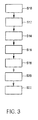
- Fig. 3 shows a flowchart of the corresponding method.
- the probe 10 is positioned on the surface 12 of the body 14.
- the converter 44 converts some of these images to depth signals 46 by summing the intensities of the image 36 along a line that corresponds to essentially constant depths in the body.
- the detector 48 uses thresholding of the depth signal 46 to detect candidate tissue layer boundaries 50.
- the selection means 52 selects from a set of such candidate tissue layer boundaries 50 a nearest candidate tissue layer boundary 54 that is nearest to the surface 12 of the body 14.
- the processing means 56 determines an actual tissue layer boundary 58 from said nearest candidate tissue layer boundaries, which were selected for various images 36.
- the actual tissue layer boundary 58 is displayed on a display 60.
- the device 8 may also comprise a user interface, e.g. for changing settings of the tissue layer measurement.
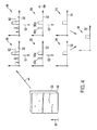
- Fig. 4 shows a schematic view of how an actual tissue layer boundary 58 is determined from 2D ultrasound images 36.
- the images 36 are summed along lines that correspond to equal depths in the body 14.
- This conversion step 44 yields two depth signals 46.
- the depth signals 46 are shown in the figure as plots, where the horizontal axis corresponds to increasing depths within the body 14.
- the vertical axis corresponds to a higher value of the summed intensities.
- the threshold 62 is indicated with a dashed line. If the value of the depth signal 46 is higher than the threshold 62, a candidate tissue layer boundary 50 is detected at this position.
- the value of the threshold 62 can either be a fixed preset value or it can be dependent on the overall average intensity in the images 36. For example the threshold 62 could be designed as ten times the average intensity of one line corresponding to constant depth within the body.
- the first candidate tissue layer boundary 50a is nearer to the surface of the body, however, it has a smaller width than the second candidate tissue layer boundary 50b. Because it is smaller than the required minimum width 64 it is rejected and the nearest candidate tissue layer boundary 54 is only chosen from among the remaining candidate tissue layer boundaries 50, in this case the second candidate tissue layer boundary 50b.
- the processing means 56 determines the actual tissue layer boundary 58 by choosing the nearest candidate tissue layer boundary value 54 that occurs most frequently. If several depth values 54 occur with the same frequency, the average of those values is chosen as actual tissue layer boundary value 58.
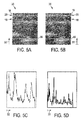
- Fig. 5A shows an acquired ultrasound image 36.
- the direction of increasing depth 32 is from top to bottom of the image, i.e., the top of the image corresponds to the surface 12 of the body 14.
- the image has rectangular dimensions, but in principle also other image dimensions would be possible.
- the image shows a fat layer 16, which is separated by a tissue layer boundary 20 from a second tissue layer 18.
- Fig. 5B shows the same ultrasound image 36 after a noise removal process which is performed using Otsu thresholding. Also shown in Figs. 5A and 5B is an example of a line 66 that corresponds to constant depth in the body 14.
- Fig. 5C shows the depth signal 46 that is obtained by summing the noise-removed image 36 across horizontal lines 66. The direction of increasing depth 32 is now plotted horizontally from left to right.
- Fig. 5D shows a derivative of the depth signal of Fig. 5C .
- the derivative in this case is computed as the absolute value of the mathematical derivative, i.e., it contains only positive values.
- Fig. 5E shows the candidate tissue layer boundaries that are detected by thresholding a sum of the depth signal and the derivative depth signal. Subsequently, an outlier removal process takes place to remove candidates that spread only over a few lines (data points on the depth signal), for example by applying median filtering. At the interface between the probe 10 and the surface 12 of the body 14 ultrasound reflection 28 can occur. Although this is not visible in Fig. 5A , it is clear that in principle this can lead to high intensities in the upper part (corresponding to an area near the surface of the body) of an image 36. It is understood that precautions are taken that these are not falsely identified as nearest candidate tissue layer boundary 54. For example the first two lines of the images 36 could be excluded from the nearest candidate tissue layer boundary detection.
- Fig. 5F shows the resulting candidate tissue layer boundaries 68 that have a tissue boundary width exceeding the minimum tissue boundary width 64.
- Fig. 5G shows the nearest candidate tissue layer boundary 54 that was selected by the selection means.
- the detection of nearest candidate tissue layer boundaries is performed in a similar way for ultrasound images 36 acquired from adjacent positions. This way, for every acquired ultrasound image 36 a nearest candidate tissue layer boundary can be determined.
- the above-mentioned conversion, detection, and selection can be applied only to a subset of the acquired images, for example only for images that were acquired from positions on the surface with at least a certain minimum distance between them.
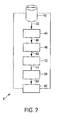
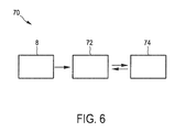
- Fig. 6 shows an example of an embodiment of a device 70 for estimating a fat- and/or fat-free mass of a body.
- the body fat estimator 72 uses actual tissue layer boundary values 58 that are determined by the device 8 for determining actual tissue layer boundaries.
- the determined actual tissue layer boundaries 58 can be shown on the user interface 74.
- the user interface 74 also provides further information about the measurement process and gives the user instructions on how to use the device 70, for example where to place the probe and how to move it.
- the user interface can comprise a (touch) screen, LEDs, dedicated buttons, and/or a loudspeaker.
- the user can also provide the device 70 with information through the user interface 74. For example, the user could enter additional data like e.g. the age and gender of the patient amongst others.
- the user can indicate whether he wants to perform a measurement e.g. at 3, 5 or 7 sites. Based on this selection, the body fat estimator 72 would use the appropriate formula. Finally, the user interface 74 shows the estimated fat- and/or fat-free mass or the estimated body density.
- a computer program may be stored/distributed on a suitable medium, such as an optical storage medium or a solid-state medium supplied together with or as part of other hardware, but may also be distributed in other forms, such as via the Internet or other wired or wireless telecommunication systems.
- a suitable medium such as an optical storage medium or a solid-state medium supplied together with or as part of other hardware, but may also be distributed in other forms, such as via the Internet or other wired or wireless telecommunication systems.
Landscapes
- Health & Medical Sciences (AREA)
- Life Sciences & Earth Sciences (AREA)
- Engineering & Computer Science (AREA)
- Medical Informatics (AREA)
- General Health & Medical Sciences (AREA)
- Physics & Mathematics (AREA)
- Surgery (AREA)
- Nuclear Medicine, Radiotherapy & Molecular Imaging (AREA)
- Biomedical Technology (AREA)
- Molecular Biology (AREA)
- Pathology (AREA)
- Animal Behavior & Ethology (AREA)
- Biophysics (AREA)
- Public Health (AREA)
- Veterinary Medicine (AREA)
- Heart & Thoracic Surgery (AREA)
- Radiology & Medical Imaging (AREA)
- Quality & Reliability (AREA)
- Computer Vision & Pattern Recognition (AREA)
- General Physics & Mathematics (AREA)
- Theoretical Computer Science (AREA)
- Ultra Sonic Daignosis Equipment (AREA)
- Measuring And Recording Apparatus For Diagnosis (AREA)
Priority Applications (1)
| Application Number | Priority Date | Filing Date | Title |
|---|---|---|---|
| EP11813435.2A EP2661228B1 (en) | 2011-01-05 | 2011-12-27 | Device and method for determining actual tissue layer boundaries of a body |
Applications Claiming Priority (3)
| Application Number | Priority Date | Filing Date | Title |
|---|---|---|---|
| EP11150150 | 2011-01-05 | ||
| PCT/IB2011/055959 WO2012093317A1 (en) | 2011-01-05 | 2011-12-27 | Device and method for determining actual tissue layer boundaries of a body |
| EP11813435.2A EP2661228B1 (en) | 2011-01-05 | 2011-12-27 | Device and method for determining actual tissue layer boundaries of a body |
Publications (2)
| Publication Number | Publication Date |
|---|---|
| EP2661228A1 EP2661228A1 (en) | 2013-11-13 |
| EP2661228B1 true EP2661228B1 (en) | 2014-12-24 |
Family
ID=45531484
Family Applications (1)
| Application Number | Title | Priority Date | Filing Date |
|---|---|---|---|
| EP11813435.2A Active EP2661228B1 (en) | 2011-01-05 | 2011-12-27 | Device and method for determining actual tissue layer boundaries of a body |
Country Status (7)
Families Citing this family (13)
| Publication number | Priority date | Publication date | Assignee | Title |
|---|---|---|---|---|
| US8517942B2 (en) | 2010-06-25 | 2013-08-27 | John C. Hill | Method for non-invasive determination of glycogen stores |
| CN103034979B (zh) * | 2012-11-30 | 2015-03-25 | 声泰特(成都)科技有限公司 | 一种超声图像清晰度提升方法 |
| RU2015138681A (ru) * | 2013-02-11 | 2017-03-16 | Конинклейке Филипс Н.В. | Система и способ ультразвуковой визуализации |
| JP6303448B2 (ja) * | 2013-11-29 | 2018-04-04 | セイコーエプソン株式会社 | 超音波測定装置 |
| US9642593B2 (en) | 2014-09-19 | 2017-05-09 | MuscleSound, LLC | System and method for non-invasive determination of human body fat |
| WO2016103839A1 (ja) * | 2014-12-22 | 2016-06-30 | オリンパス株式会社 | 超音波診断装置、超音波診断装置の作動方法および超音波診断装置の作動プログラム |
| WO2017056779A1 (ja) * | 2015-09-29 | 2017-04-06 | 古野電気株式会社 | 超音波組織検出装置、超音波組織検出方法、および、超音波組織検出プログラム |
| US11013490B2 (en) | 2016-11-15 | 2021-05-25 | Musclesound, Inc. | Non-invasive determination of muscle tissue size |
| US11064971B2 (en) | 2016-11-30 | 2021-07-20 | Musclesound, Inc. | Non-Invasive determination of muscle tissue quality and intramuscular fat |
| CN107049240A (zh) * | 2017-01-18 | 2017-08-18 | 英华达(上海)科技有限公司 | 身体年龄计算方法及体脂测量系统 |
| US11096658B2 (en) | 2017-02-02 | 2021-08-24 | Musclesound, Inc. | Non-invasive determination of pennation angle and/or fascicle length |
| US11160493B2 (en) | 2017-03-03 | 2021-11-02 | Musclesound, Inc. | System and method for determining a subject's muscle fuel level, muscle fuel rating, and muscle energy status |
| CN110313938B (zh) * | 2019-08-01 | 2021-03-23 | 无锡海斯凯尔医学技术有限公司 | 皮下组织厚度测量方法、装置、设备及存储介质 |
Family Cites Families (24)
| Publication number | Priority date | Publication date | Assignee | Title |
|---|---|---|---|---|
| JP2759808B2 (ja) * | 1988-10-05 | 1998-05-28 | 株式会社日立メディコ | 超音波診断装置 |
| US5520183A (en) * | 1991-12-19 | 1996-05-28 | Meat Research Corporation | Fat depth measuring apparatus |
| JPH05176925A (ja) * | 1991-12-27 | 1993-07-20 | Shimadzu Corp | 皮下脂肪計測装置 |
| US5734739A (en) * | 1994-05-31 | 1998-03-31 | University Of Washington | Method for determining the contour of an in vivo organ using multiple image frames of the organ |
| US5941825A (en) * | 1996-10-21 | 1999-08-24 | Philipp Lang | Measurement of body fat using ultrasound methods and devices |
| JP2889568B1 (ja) * | 1998-05-18 | 1999-05-10 | 正男 伊藤 | 血管膜厚測定装置及び動脈硬化診断装置 |
| JP2000350727A (ja) | 1999-06-11 | 2000-12-19 | Tanita Corp | 体脂肪分布の測定方法及び測定装置 |
| WO2003009762A1 (en) * | 2001-07-24 | 2003-02-06 | Sunlight Medical, Ltd. | Joint analysis using ultrasound |
| JP4785105B2 (ja) | 2001-08-03 | 2011-10-05 | 株式会社日立メディコ | 超音波画像処理装置 |
| KR100438903B1 (ko) | 2002-01-31 | 2004-07-02 | 한국전자통신연구원 | 초음파 영상으로부터 대상 장기의 지방량을 정량적으로 측정하는 장비 |
| US6835177B2 (en) * | 2002-11-06 | 2004-12-28 | Sonosite, Inc. | Ultrasonic blood vessel measurement apparatus and method |
| US7727153B2 (en) * | 2003-04-07 | 2010-06-01 | Sonosite, Inc. | Ultrasonic blood vessel measurement apparatus and method |
| FR2861199B1 (fr) | 2003-10-20 | 2006-02-10 | Centre Nat Rech Scient | Procede et systeme de determination de la masse grasse corporelle totale, procede et systeme de determination de la composition corporelle |
| US7090640B2 (en) * | 2003-11-12 | 2006-08-15 | Q-Vision | System and method for automatic determination of a region of interest within an image |
| US20080205719A1 (en) | 2005-06-15 | 2008-08-28 | Koninklijke Philips Electronics, N.V. | Method of Model-Based Elastic Image Registration For Comparing a First and a Second Image |
| WO2008023618A1 (en) * | 2006-08-21 | 2008-02-28 | Tohoku University | Ultrasonograph |
| ITPI20060105A1 (it) * | 2006-08-28 | 2008-02-29 | C N R Consiglio Naz Delle Ricerche | Apparecchiatura per la localizzazione automatica delle interfacce lume-intima e media-avventizia in un vaso sanguigno. |
| US7856130B2 (en) * | 2007-03-28 | 2010-12-21 | Eigen, Inc. | Object recognition system for medical imaging |
| US8450703B2 (en) | 2007-07-27 | 2013-05-28 | Koninklijke Philips Electronics N.V. | Method and system for imaging samples |
| US8135179B2 (en) * | 2008-05-05 | 2012-03-13 | Biotronics, Inc. | Systems, methods and devices for use in assessing fat and muscle depth |
| US20100036246A1 (en) | 2008-08-07 | 2010-02-11 | Leonid Kushculey | Automatic fat thickness measurements |
| KR101150005B1 (ko) * | 2008-11-19 | 2012-06-01 | 삼성메디슨 주식회사 | Imt 측정 영역 설정 방법 및 초음파 장치 |
| US9014452B2 (en) * | 2013-08-21 | 2015-04-21 | Seiko Epson Corporation | Orientation-aware average intensity histogram to indicate object boundary depth in ultrasound images |
| US8995739B2 (en) * | 2013-08-21 | 2015-03-31 | Seiko Epson Corporation | Ultrasound image object boundary localization by intensity histogram classification using relationships among boundaries |
-
2011
- 2011-12-27 JP JP2013547923A patent/JP5925215B2/ja active Active
- 2011-12-27 BR BR112013017069A patent/BR112013017069A2/pt not_active IP Right Cessation
- 2011-12-27 RU RU2013136486/14A patent/RU2013136486A/ru not_active Application Discontinuation
- 2011-12-27 EP EP11813435.2A patent/EP2661228B1/en active Active
- 2011-12-27 CN CN201180064347.7A patent/CN103429163B/zh active Active
- 2011-12-27 US US13/997,482 patent/US9579079B2/en active Active
- 2011-12-27 WO PCT/IB2011/055959 patent/WO2012093317A1/en active Application Filing
Also Published As
| Publication number | Publication date |
|---|---|
| CN103429163B (zh) | 2015-07-08 |
| US9579079B2 (en) | 2017-02-28 |
| JP5925215B2 (ja) | 2016-05-25 |
| EP2661228A1 (en) | 2013-11-13 |
| US20130289409A1 (en) | 2013-10-31 |
| RU2013136486A (ru) | 2015-02-10 |
| BR112013017069A2 (pt) | 2019-09-24 |
| CN103429163A (zh) | 2013-12-04 |
| WO2012093317A1 (en) | 2012-07-12 |
| JP2014501593A (ja) | 2014-01-23 |
Similar Documents
| Publication | Publication Date | Title |
|---|---|---|
| EP2661228B1 (en) | Device and method for determining actual tissue layer boundaries of a body | |
| EP3432803B1 (en) | Ultrasound system and method for detecting lung sliding | |
| US20150374343A1 (en) | Ultrasound imaging system and method | |
| EP3223697B1 (en) | Apparatus and method for analyzing body tissue layer in electronic device | |
| US20150359520A1 (en) | Ultrasound probe and ultrasound imaging system | |
| RU2677191C2 (ru) | Установление границ блокирования ребром в анатомически интеллектуальной эхокардиографии | |
| WO2017210778A1 (en) | A method and system for estimating fractional fact content of an object | |
| CN111031927B (zh) | 肺部超声中b线的检测、呈现和报告 | |
| US20190261942A1 (en) | Thrombus detection during scanning | |
| Soleimani et al. | Carotid artery wall motion estimation from consecutive ultrasonic images: Comparison between block-matching and maximum-gradient algorithms | |
| US20200143532A1 (en) | Method and apparatus for analyzing abdominal disease based on medical image | |
| CN103260526A (zh) | 具有峰值强度检测功能的超声成像系统和方法 | |
| US20200253580A1 (en) | Tissue lesion detection and determination using quantitative transmission ultrasound | |
| CN116419716A (zh) | 周期性参数的分析方法和超声成像系统 | |
| WO2013084093A1 (en) | Device for ultrasound imaging | |
| CN102217953B (zh) | 基于多邻域辅助二维超声形变组织图像跟踪方法及装置 | |
| CN106999159B (zh) | 用于将组织性质可视化的装置 | |
| Ito et al. | Rapid and accurate assessment of aortic arch atherosclerosis using simultaneous multi-plane imaging by transesophageal echocardiography | |
| JP4251918B2 (ja) | 超音波診断装置 | |
| CN113164158B (zh) | 用于检测骨折的装置和方法 | |
| JP2021180730A (ja) | 超音波診断装置及び診断支援方法 | |
| CN117281549A (zh) | 超声成像方法和装置 |
Legal Events
| Date | Code | Title | Description |
|---|---|---|---|
| PUAI | Public reference made under article 153(3) epc to a published international application that has entered the european phase |
Free format text: ORIGINAL CODE: 0009012 |
|
| 17P | Request for examination filed |
Effective date: 20130805 |
|
| AK | Designated contracting states |
Kind code of ref document: A1 Designated state(s): AL AT BE BG CH CY CZ DE DK EE ES FI FR GB GR HR HU IE IS IT LI LT LU LV MC MK MT NL NO PL PT RO RS SE SI SK SM TR |
|
| DAX | Request for extension of the european patent (deleted) | ||
| GRAP | Despatch of communication of intention to grant a patent |
Free format text: ORIGINAL CODE: EPIDOSNIGR1 |
|
| RIC1 | Information provided on ipc code assigned before grant |
Ipc: A61B 8/00 20060101ALN20140709BHEP Ipc: G06T 7/00 20060101ALI20140709BHEP Ipc: A61B 8/08 20060101AFI20140709BHEP Ipc: A61B 5/00 20060101ALI20140709BHEP |
|
| INTG | Intention to grant announced |
Effective date: 20140722 |
|
| GRAS | Grant fee paid |
Free format text: ORIGINAL CODE: EPIDOSNIGR3 |
|
| GRAA | (expected) grant |
Free format text: ORIGINAL CODE: 0009210 |
|
| AK | Designated contracting states |
Kind code of ref document: B1 Designated state(s): AL AT BE BG CH CY CZ DE DK EE ES FI FR GB GR HR HU IE IS IT LI LT LU LV MC MK MT NL NO PL PT RO RS SE SI SK SM TR |
|
| REG | Reference to a national code |
Ref country code: GB Ref legal event code: FG4D |
|
| REG | Reference to a national code |
Ref country code: CH Ref legal event code: EP |
|
| REG | Reference to a national code |
Ref country code: IE Ref legal event code: FG4D |
|
| REG | Reference to a national code |
Ref country code: AT Ref legal event code: REF Ref document number: 702717 Country of ref document: AT Kind code of ref document: T Effective date: 20150115 |
|
| REG | Reference to a national code |
Ref country code: DE Ref legal event code: R096 Ref document number: 602011012610 Country of ref document: DE Effective date: 20150219 |
|
| REG | Reference to a national code |
Ref country code: NL Ref legal event code: VDEP Effective date: 20141224 |
|
| PG25 | Lapsed in a contracting state [announced via postgrant information from national office to epo] |
Ref country code: LT Free format text: LAPSE BECAUSE OF FAILURE TO SUBMIT A TRANSLATION OF THE DESCRIPTION OR TO PAY THE FEE WITHIN THE PRESCRIBED TIME-LIMIT Effective date: 20141224 Ref country code: NO Free format text: LAPSE BECAUSE OF FAILURE TO SUBMIT A TRANSLATION OF THE DESCRIPTION OR TO PAY THE FEE WITHIN THE PRESCRIBED TIME-LIMIT Effective date: 20150324 Ref country code: FI Free format text: LAPSE BECAUSE OF FAILURE TO SUBMIT A TRANSLATION OF THE DESCRIPTION OR TO PAY THE FEE WITHIN THE PRESCRIBED TIME-LIMIT Effective date: 20141224 |
|
| REG | Reference to a national code |
Ref country code: LT Ref legal event code: MG4D |
|
| PG25 | Lapsed in a contracting state [announced via postgrant information from national office to epo] |
Ref country code: HR Free format text: LAPSE BECAUSE OF FAILURE TO SUBMIT A TRANSLATION OF THE DESCRIPTION OR TO PAY THE FEE WITHIN THE PRESCRIBED TIME-LIMIT Effective date: 20141224 Ref country code: GR Free format text: LAPSE BECAUSE OF FAILURE TO SUBMIT A TRANSLATION OF THE DESCRIPTION OR TO PAY THE FEE WITHIN THE PRESCRIBED TIME-LIMIT Effective date: 20150325 Ref country code: RS Free format text: LAPSE BECAUSE OF FAILURE TO SUBMIT A TRANSLATION OF THE DESCRIPTION OR TO PAY THE FEE WITHIN THE PRESCRIBED TIME-LIMIT Effective date: 20141224 Ref country code: LV Free format text: LAPSE BECAUSE OF FAILURE TO SUBMIT A TRANSLATION OF THE DESCRIPTION OR TO PAY THE FEE WITHIN THE PRESCRIBED TIME-LIMIT Effective date: 20141224 Ref country code: SE Free format text: LAPSE BECAUSE OF FAILURE TO SUBMIT A TRANSLATION OF THE DESCRIPTION OR TO PAY THE FEE WITHIN THE PRESCRIBED TIME-LIMIT Effective date: 20141224 |
|
| REG | Reference to a national code |
Ref country code: AT Ref legal event code: MK05 Ref document number: 702717 Country of ref document: AT Kind code of ref document: T Effective date: 20141224 |
|
| PG25 | Lapsed in a contracting state [announced via postgrant information from national office to epo] |
Ref country code: BE Free format text: LAPSE BECAUSE OF NON-PAYMENT OF DUE FEES Effective date: 20141231 Ref country code: NL Free format text: LAPSE BECAUSE OF FAILURE TO SUBMIT A TRANSLATION OF THE DESCRIPTION OR TO PAY THE FEE WITHIN THE PRESCRIBED TIME-LIMIT Effective date: 20141224 |
|
| PG25 | Lapsed in a contracting state [announced via postgrant information from national office to epo] |
Ref country code: CZ Free format text: LAPSE BECAUSE OF FAILURE TO SUBMIT A TRANSLATION OF THE DESCRIPTION OR TO PAY THE FEE WITHIN THE PRESCRIBED TIME-LIMIT Effective date: 20141224 Ref country code: RO Free format text: LAPSE BECAUSE OF FAILURE TO SUBMIT A TRANSLATION OF THE DESCRIPTION OR TO PAY THE FEE WITHIN THE PRESCRIBED TIME-LIMIT Effective date: 20141224 Ref country code: EE Free format text: LAPSE BECAUSE OF FAILURE TO SUBMIT A TRANSLATION OF THE DESCRIPTION OR TO PAY THE FEE WITHIN THE PRESCRIBED TIME-LIMIT Effective date: 20141224 Ref country code: SK Free format text: LAPSE BECAUSE OF FAILURE TO SUBMIT A TRANSLATION OF THE DESCRIPTION OR TO PAY THE FEE WITHIN THE PRESCRIBED TIME-LIMIT Effective date: 20141224 Ref country code: ES Free format text: LAPSE BECAUSE OF FAILURE TO SUBMIT A TRANSLATION OF THE DESCRIPTION OR TO PAY THE FEE WITHIN THE PRESCRIBED TIME-LIMIT Effective date: 20141224 |
|
| REG | Reference to a national code |
Ref country code: CH Ref legal event code: PL |
|
| PG25 | Lapsed in a contracting state [announced via postgrant information from national office to epo] |
Ref country code: AT Free format text: LAPSE BECAUSE OF FAILURE TO SUBMIT A TRANSLATION OF THE DESCRIPTION OR TO PAY THE FEE WITHIN THE PRESCRIBED TIME-LIMIT Effective date: 20141224 Ref country code: PL Free format text: LAPSE BECAUSE OF FAILURE TO SUBMIT A TRANSLATION OF THE DESCRIPTION OR TO PAY THE FEE WITHIN THE PRESCRIBED TIME-LIMIT Effective date: 20141224 Ref country code: IS Free format text: LAPSE BECAUSE OF FAILURE TO SUBMIT A TRANSLATION OF THE DESCRIPTION OR TO PAY THE FEE WITHIN THE PRESCRIBED TIME-LIMIT Effective date: 20150424 |
|
| REG | Reference to a national code |
Ref country code: IE Ref legal event code: MM4A |
|
| REG | Reference to a national code |
Ref country code: DE Ref legal event code: R097 Ref document number: 602011012610 Country of ref document: DE |
|
| PG25 | Lapsed in a contracting state [announced via postgrant information from national office to epo] |
Ref country code: MC Free format text: LAPSE BECAUSE OF FAILURE TO SUBMIT A TRANSLATION OF THE DESCRIPTION OR TO PAY THE FEE WITHIN THE PRESCRIBED TIME-LIMIT Effective date: 20141224 |
|
| PG25 | Lapsed in a contracting state [announced via postgrant information from national office to epo] |
Ref country code: LI Free format text: LAPSE BECAUSE OF NON-PAYMENT OF DUE FEES Effective date: 20141231 Ref country code: DK Free format text: LAPSE BECAUSE OF FAILURE TO SUBMIT A TRANSLATION OF THE DESCRIPTION OR TO PAY THE FEE WITHIN THE PRESCRIBED TIME-LIMIT Effective date: 20141224 Ref country code: CH Free format text: LAPSE BECAUSE OF NON-PAYMENT OF DUE FEES Effective date: 20141231 Ref country code: IE Free format text: LAPSE BECAUSE OF NON-PAYMENT OF DUE FEES Effective date: 20141227 |
|
| PLBE | No opposition filed within time limit |
Free format text: ORIGINAL CODE: 0009261 |
|
| STAA | Information on the status of an ep patent application or granted ep patent |
Free format text: STATUS: NO OPPOSITION FILED WITHIN TIME LIMIT |
|
| 26N | No opposition filed |
Effective date: 20150925 |
|
| REG | Reference to a national code |
Ref country code: FR Ref legal event code: PLFP Year of fee payment: 5 |
|
| PG25 | Lapsed in a contracting state [announced via postgrant information from national office to epo] |
Ref country code: IT Free format text: LAPSE BECAUSE OF FAILURE TO SUBMIT A TRANSLATION OF THE DESCRIPTION OR TO PAY THE FEE WITHIN THE PRESCRIBED TIME-LIMIT Effective date: 20141224 |
|
| PG25 | Lapsed in a contracting state [announced via postgrant information from national office to epo] |
Ref country code: SI Free format text: LAPSE BECAUSE OF FAILURE TO SUBMIT A TRANSLATION OF THE DESCRIPTION OR TO PAY THE FEE WITHIN THE PRESCRIBED TIME-LIMIT Effective date: 20141224 |
|
| PG25 | Lapsed in a contracting state [announced via postgrant information from national office to epo] |
Ref country code: SM Free format text: LAPSE BECAUSE OF FAILURE TO SUBMIT A TRANSLATION OF THE DESCRIPTION OR TO PAY THE FEE WITHIN THE PRESCRIBED TIME-LIMIT Effective date: 20141224 |
|
| PG25 | Lapsed in a contracting state [announced via postgrant information from national office to epo] |
Ref country code: BE Free format text: LAPSE BECAUSE OF FAILURE TO SUBMIT A TRANSLATION OF THE DESCRIPTION OR TO PAY THE FEE WITHIN THE PRESCRIBED TIME-LIMIT Effective date: 20141224 |
|
| PG25 | Lapsed in a contracting state [announced via postgrant information from national office to epo] |
Ref country code: BG Free format text: LAPSE BECAUSE OF FAILURE TO SUBMIT A TRANSLATION OF THE DESCRIPTION OR TO PAY THE FEE WITHIN THE PRESCRIBED TIME-LIMIT Effective date: 20141224 Ref country code: CY Free format text: LAPSE BECAUSE OF FAILURE TO SUBMIT A TRANSLATION OF THE DESCRIPTION OR TO PAY THE FEE WITHIN THE PRESCRIBED TIME-LIMIT Effective date: 20141224 Ref country code: PT Free format text: LAPSE BECAUSE OF FAILURE TO SUBMIT A TRANSLATION OF THE DESCRIPTION OR TO PAY THE FEE WITHIN THE PRESCRIBED TIME-LIMIT Effective date: 20141224 |
|
| PG25 | Lapsed in a contracting state [announced via postgrant information from national office to epo] |
Ref country code: LU Free format text: LAPSE BECAUSE OF NON-PAYMENT OF DUE FEES Effective date: 20141227 Ref country code: MT Free format text: LAPSE BECAUSE OF FAILURE TO SUBMIT A TRANSLATION OF THE DESCRIPTION OR TO PAY THE FEE WITHIN THE PRESCRIBED TIME-LIMIT Effective date: 20141224 Ref country code: HU Free format text: LAPSE BECAUSE OF FAILURE TO SUBMIT A TRANSLATION OF THE DESCRIPTION OR TO PAY THE FEE WITHIN THE PRESCRIBED TIME-LIMIT; INVALID AB INITIO Effective date: 20111227 |
|
| REG | Reference to a national code |
Ref country code: FR Ref legal event code: PLFP Year of fee payment: 6 |
|
| PGFP | Annual fee paid to national office [announced via postgrant information from national office to epo] |
Ref country code: TR Payment date: 20141227 Year of fee payment: 4 |
|
| REG | Reference to a national code |
Ref country code: FR Ref legal event code: PLFP Year of fee payment: 7 |
|
| PG25 | Lapsed in a contracting state [announced via postgrant information from national office to epo] |
Ref country code: MK Free format text: LAPSE BECAUSE OF FAILURE TO SUBMIT A TRANSLATION OF THE DESCRIPTION OR TO PAY THE FEE WITHIN THE PRESCRIBED TIME-LIMIT Effective date: 20141224 |
|
| PG25 | Lapsed in a contracting state [announced via postgrant information from national office to epo] |
Ref country code: AL Free format text: LAPSE BECAUSE OF FAILURE TO SUBMIT A TRANSLATION OF THE DESCRIPTION OR TO PAY THE FEE WITHIN THE PRESCRIBED TIME-LIMIT Effective date: 20141224 |
|
| PG25 | Lapsed in a contracting state [announced via postgrant information from national office to epo] |
Ref country code: TR Free format text: LAPSE BECAUSE OF NON-PAYMENT OF DUE FEES Effective date: 20161227 |
|
| PGFP | Annual fee paid to national office [announced via postgrant information from national office to epo] |
Ref country code: GB Payment date: 20231219 Year of fee payment: 13 |
|
| PGFP | Annual fee paid to national office [announced via postgrant information from national office to epo] |
Ref country code: FR Payment date: 20231226 Year of fee payment: 13 |
|
| REG | Reference to a national code |
Ref country code: DE Ref legal event code: R084 Ref document number: 602011012610 Country of ref document: DE |
|
| PGFP | Annual fee paid to national office [announced via postgrant information from national office to epo] |
Ref country code: DE Payment date: 20231227 Year of fee payment: 13 |
|
| REG | Reference to a national code |
Ref country code: GB Ref legal event code: 746 Effective date: 20240620 |
|
| REG | Reference to a national code |
Ref country code: DE Ref legal event code: R119 Ref document number: 602011012610 Country of ref document: DE |
|
| GBPC | Gb: european patent ceased through non-payment of renewal fee |
Effective date: 20241227 |