EP2660356A1 - Organic compound hydrogenation device and hydrogenation method - Google Patents
Organic compound hydrogenation device and hydrogenation method Download PDFInfo
- Publication number
- EP2660356A1 EP2660356A1 EP11854409.7A EP11854409A EP2660356A1 EP 2660356 A1 EP2660356 A1 EP 2660356A1 EP 11854409 A EP11854409 A EP 11854409A EP 2660356 A1 EP2660356 A1 EP 2660356A1
- Authority
- EP
- European Patent Office
- Prior art keywords
- organic compound
- electrode
- hydrogenation
- reducing electrode
- collector layer
- Prior art date
- Legal status (The legal status is an assumption and is not a legal conclusion. Google has not performed a legal analysis and makes no representation as to the accuracy of the status listed.)
- Withdrawn
Links
Images




Classifications
-
- C—CHEMISTRY; METALLURGY
- C25—ELECTROLYTIC OR ELECTROPHORETIC PROCESSES; APPARATUS THEREFOR
- C25B—ELECTROLYTIC OR ELECTROPHORETIC PROCESSES FOR THE PRODUCTION OF COMPOUNDS OR NON-METALS; APPARATUS THEREFOR
- C25B13/00—Diaphragms; Spacing elements
- C25B13/02—Diaphragms; Spacing elements characterised by shape or form
-
- C—CHEMISTRY; METALLURGY
- C01—INORGANIC CHEMISTRY
- C01B—NON-METALLIC ELEMENTS; COMPOUNDS THEREOF; METALLOIDS OR COMPOUNDS THEREOF NOT COVERED BY SUBCLASS C01C
- C01B13/00—Oxygen; Ozone; Oxides or hydroxides in general
- C01B13/02—Preparation of oxygen
- C01B13/0203—Preparation of oxygen from inorganic compounds
- C01B13/0207—Water
-
- C—CHEMISTRY; METALLURGY
- C01—INORGANIC CHEMISTRY
- C01B—NON-METALLIC ELEMENTS; COMPOUNDS THEREOF; METALLOIDS OR COMPOUNDS THEREOF NOT COVERED BY SUBCLASS C01C
- C01B13/00—Oxygen; Ozone; Oxides or hydroxides in general
- C01B13/02—Preparation of oxygen
- C01B13/0229—Purification or separation processes
- C01B13/0248—Physical processing only
-
- C—CHEMISTRY; METALLURGY
- C01—INORGANIC CHEMISTRY
- C01B—NON-METALLIC ELEMENTS; COMPOUNDS THEREOF; METALLOIDS OR COMPOUNDS THEREOF NOT COVERED BY SUBCLASS C01C
- C01B3/00—Hydrogen; Gaseous mixtures containing hydrogen; Separation of hydrogen from mixtures containing it; Purification of hydrogen; Reversible storage of hydrogen
- C01B3/0005—Reversible storage of hydrogen, e.g. by hydrogen getters or electrodes
- C01B3/001—Reversible storage of hydrogen, e.g. by hydrogen getters or electrodes characterised by the uptaking media; Treatment thereof
- C01B3/0015—Organic compounds, e.g. liquid organic hydrogen carriers [LOHC] or metalorganic compounds; Solutions thereof
-
- C—CHEMISTRY; METALLURGY
- C25—ELECTROLYTIC OR ELECTROPHORETIC PROCESSES; APPARATUS THEREFOR
- C25B—ELECTROLYTIC OR ELECTROPHORETIC PROCESSES FOR THE PRODUCTION OF COMPOUNDS OR NON-METALS; APPARATUS THEREFOR
- C25B3/00—Electrolytic production of organic compounds
- C25B3/01—Products
- C25B3/03—Acyclic or carbocyclic hydrocarbons
-
- C—CHEMISTRY; METALLURGY
- C25—ELECTROLYTIC OR ELECTROPHORETIC PROCESSES; APPARATUS THEREFOR
- C25B—ELECTROLYTIC OR ELECTROPHORETIC PROCESSES FOR THE PRODUCTION OF COMPOUNDS OR NON-METALS; APPARATUS THEREFOR
- C25B3/00—Electrolytic production of organic compounds
- C25B3/20—Processes
- C25B3/25—Reduction
-
- C—CHEMISTRY; METALLURGY
- C25—ELECTROLYTIC OR ELECTROPHORETIC PROCESSES; APPARATUS THEREFOR
- C25B—ELECTROLYTIC OR ELECTROPHORETIC PROCESSES FOR THE PRODUCTION OF COMPOUNDS OR NON-METALS; APPARATUS THEREFOR
- C25B9/00—Cells or assemblies of cells; Constructional parts of cells; Assemblies of constructional parts, e.g. electrode-diaphragm assemblies; Process-related cell features
- C25B9/17—Cells comprising dimensionally-stable non-movable electrodes; Assemblies of constructional parts thereof
- C25B9/19—Cells comprising dimensionally-stable non-movable electrodes; Assemblies of constructional parts thereof with diaphragms
-
- C—CHEMISTRY; METALLURGY
- C25—ELECTROLYTIC OR ELECTROPHORETIC PROCESSES; APPARATUS THEREFOR
- C25B—ELECTROLYTIC OR ELECTROPHORETIC PROCESSES FOR THE PRODUCTION OF COMPOUNDS OR NON-METALS; APPARATUS THEREFOR
- C25B9/00—Cells or assemblies of cells; Constructional parts of cells; Assemblies of constructional parts, e.g. electrode-diaphragm assemblies; Process-related cell features
- C25B9/17—Cells comprising dimensionally-stable non-movable electrodes; Assemblies of constructional parts thereof
- C25B9/19—Cells comprising dimensionally-stable non-movable electrodes; Assemblies of constructional parts thereof with diaphragms
- C25B9/23—Cells comprising dimensionally-stable non-movable electrodes; Assemblies of constructional parts thereof with diaphragms comprising ion-exchange membranes in or on which electrode material is embedded
-
- Y—GENERAL TAGGING OF NEW TECHNOLOGICAL DEVELOPMENTS; GENERAL TAGGING OF CROSS-SECTIONAL TECHNOLOGIES SPANNING OVER SEVERAL SECTIONS OF THE IPC; TECHNICAL SUBJECTS COVERED BY FORMER USPC CROSS-REFERENCE ART COLLECTIONS [XRACs] AND DIGESTS
- Y02—TECHNOLOGIES OR APPLICATIONS FOR MITIGATION OR ADAPTATION AGAINST CLIMATE CHANGE
- Y02E—REDUCTION OF GREENHOUSE GAS [GHG] EMISSIONS, RELATED TO ENERGY GENERATION, TRANSMISSION OR DISTRIBUTION
- Y02E60/00—Enabling technologies; Technologies with a potential or indirect contribution to GHG emissions mitigation
- Y02E60/30—Hydrogen technology
- Y02E60/32—Hydrogen storage
-
- Y—GENERAL TAGGING OF NEW TECHNOLOGICAL DEVELOPMENTS; GENERAL TAGGING OF CROSS-SECTIONAL TECHNOLOGIES SPANNING OVER SEVERAL SECTIONS OF THE IPC; TECHNICAL SUBJECTS COVERED BY FORMER USPC CROSS-REFERENCE ART COLLECTIONS [XRACs] AND DIGESTS
- Y02—TECHNOLOGIES OR APPLICATIONS FOR MITIGATION OR ADAPTATION AGAINST CLIMATE CHANGE
- Y02P—CLIMATE CHANGE MITIGATION TECHNOLOGIES IN THE PRODUCTION OR PROCESSING OF GOODS
- Y02P20/00—Technologies relating to chemical industry
- Y02P20/10—Process efficiency
- Y02P20/133—Renewable energy sources, e.g. sunlight
Definitions
- the present invention relates to an organic compound hydrogenation device and hydrogenation method.
- Organic hydride systems are known as methods for storing and transporting hydrogen, wherein hydrogen gas is first reacted with benzene, toluene or the like to obtain a cyclic saturated hydrocarbon, and the product is then transported to an energy consumption area and hydrogen is generated at the consumption area (see Patent Literatures 1 to 4 and Non-Patent Literature 1).
- the hydrogenation device for organic compound(s) comprises an oxidation chamber, a reduction chamber, an electrolyte membrane, an oxidizing electrode and a reducing electrode.
- the oxidation chamber holds a water-containing electrolyte.
- the reduction chamber holds an organic compound(s) with an unsaturated bond (unsaturated bonds).
- the organic compound(s) with an unsaturated bond will hereunder sometimes be referred to simply as "unsaturated compound(s)".
- the electrolyte membrane separates the electrolyte held in the oxidation chamber from the organic compound(s) held in the reduction chamber, and it is ion-permeable.
- the oxidizing electrode generates protons from the water held in the oxidation chamber.
- the reducing electrode hydrogenates the organic compound(s) held in the reduction chamber.
- the hydrogenation device for organic compound(s) comprises an oxidation chamber, a reduction chamber, a proton-conductive electrolyte membrane, an oxidizing electrode and a reducing electrode.
- the oxidation chamber holds a water-containing electrolyte.
- the reduction chamber holds an organic compound(s) with an unsaturated bond (unsaturated bonds).
- the electrolyte membrane separates the interior of the oxidation chamber from the interior of the reduction chamber.
- the oxidizing electrode is situated inside the oxidation chamber.
- the reducing electrode is adjacent to the electrolyte membrane and contacts with the organic compound(s) in the reduction chamber to hydrogenate the organic compound(s).
- the hydrogenation device comprises a membrane-electrode assembly (MEA) having an electron collector layer that allows permeation of the organic compound(s), the reducing electrode and the electrolyte membrane, wherein the reducing electrode is situated between the electron collector layer and the electrolyte membrane, the electrolyte membrane covers the electron collector layer and the reducing electrode, and the electrolyte membrane has an opening exposing the section of the side of the electron collector layer opposite the reducing electrode.
- MEA membrane-electrode assembly
- the hydrogenation device comprises a membrane-electrode assembly having an electron collector layer that allows permeation of the organic compound(s), the reducing electrode formed on one side of the electron collector layer, and the electrolyte membrane covering the electron collector layer and the reducing electrode, wherein an opening is formed on a section of the electrolyte membrane located on the side opposite the reducing electrode sandwiching the electron collector layer, the opening faces the inside of the reduction chamber, and the back side of the section of the electron collector layer on which the reducing electrode has been formed is exposed through the opening.
- the hydrogenation device according to the first aspect and the second aspect of the invention may also comprise a power source that applies a voltage to the oxidizing electrode and the reducing electrode.
- the hydrogenation device according to the first aspect and the second aspect of the invention may also comprise a conductor wire that connects the oxidizing electrode and the power source, and a conductor wire that connects the reducing electrode and the power source.
- the hydrogenation method for organic compound(s) according to the third aspect of the invention is a method wherein a hydrogenation device according to the first aspect or second aspect of the invention as described above is used to apply a voltage to the oxidizing electrode and the reducing electrode through the conductor wires, causing generation of oxygen at the oxidizing electrode and hydrogenation of the organic compound(s) at the reducing electrode.
- the organic compound(s) is preferably at least one selected from the group consisting of benzene, toluene, xylene, ethylbenzene, naphthalene, methylnaphthalene and tetralin.
- the organic compound(s) is preferably a liquid hydrocarbon that undergoes phase separation with water.
- the organic compound(s) and a hydride of the organic compound(s) (hydrogenation product) in the reduction chamber are both preferably present as liquids.
- the hydrogenation device 1a illustrated in Figs. 11 and 12 is used for hydrogenation of an unsaturated compound(s) 4 (an organic compound(s) with unsaturated bonds). Hydrogenation of the unsaturated compound(s) 4 may be carried out, for example, in an ordinary temperature, ordinary pressure environment.
- the hydrogenation device 1a comprises a reduction chamber 2, an oxidation chamber 3, and a membrane-electrode assembly 6a partitioning the reduction chamber 2 and oxidation chamber 3.
- the reduction chamber 2 and oxidation chamber 3 are connected via the membrane-electrode assembly 6a.
- the supporting electrolyte 5 used may be one that is stable in terms of oxidation-reduction potential, and that has the necessary proton conductivity.
- the supporting electrolyte 5 used may be a solid polymer electrolyte membrane imbibed with an aqueous sodium sulfate solution, dilute sulfuric acid and water. If necessary, an inert gas such as nitrogen may be supplied into the supporting electrolyte 5 from the exterior, through a gas tube 11.
- the oxidizing electrode 7 is situated in the supporting electrolyte 5 of the oxidation chamber 3.
- the oxidizing electrode 7 is composed of an oxidation active component, and it has the function of generating protons and oxygen from water.
- the oxidation active component may be a precious metal, transition element, oxide, nitride, sulfide, selenide, oxynitride, thionitride or the like. Of these, precious metals are preferred from the viewpoint of stability under a strongly acidic atmosphere.
- precious metals include platinum (Pt), palladium (Pd), rhodium (Rh), ruthenium (Ru), iridium (Ir) and osmium (Os).
- Transition elements include titanium (Ti), vanadium (V), chromium (Cr), manganese (Mn), iron (Fe), cobalt (Co), nickel (Ni), copper (Cu), zirconium (Zr), niobium (Nb), molybdenum (Mo), silver (Ag) and lanthanum (La).
- Catalysts having the aforementioned oxidation active components supported on an appropriate support are also preferred as constituent materials for the oxidizing electrode 7.
- the support may be one with electrical conductivity, composed of a material with a large surface area.
- the unsaturated compound(s) 4 (preferably a liquid unsaturated compound(s) 4) is present in the reduction chamber 2.
- an inert gas such as nitrogen may be supplied into the unsaturated compound(s) 4 from the exterior, through the gas tube 10.
- the membrane-electrode assembly 6a has an electron collector layer 22, a reducing electrode 24 and an electrolyte membrane 20 layered in that order.
- the electron collector layer 22 contacts with the unsaturated compound(s) 4 present in the reduction chamber 2.
- the electrolyte membrane 20 contacts with the water-containing supporting electrolyte 5 present in the oxidation chamber 3.
- the reducing electrode 24 is sandwiched between the electrolyte membrane 20 and the electron collector layer 22, and contacts with the electrolyte membrane 20 and the electron collector layer 22.
- the reducing electrode 24 is in close contact with the electrolyte membrane 20 and the electron collector layer 22.
- the electrolyte membrane 20 is ion-permeable (preferably with proton conductivity).
- the electrolyte membrane 20 has a function of preventing mixture between the supporting electrolyte 5 in the oxidation chamber 3 and the unsaturated compound(s) 4 in the reduction chamber 2.
- the electrolyte membrane 20 may be a solid polymer membrane, a fluorine resin-based ion exchange membrane or a membrane comprising a liquid with ionic conductivity (such as an ionic liquid, sulfuric acid or phosphoric acid) impregnated in the pores of a porous ceramic membrane.
- the solid polymer membrane may be a perfluorosulfonic acid-based proton-exchange membrane, among which NAFION membranes (registered trademark of DuPont Corp.) is preferred from the viewpoint of the ion permeation rate.
- the thickness of the solid polymer membrane will differ depending on the conditions, but it is preferably 10 to 500 ⁇ m from the viewpoint of hydrogen ion permeability and mechanical strength.
- the fluorine resin-based ion exchange membrane may be an Aciplex membrane (registered trademark of Asahi Kasei Corp.) or a Flemion membrane (registered trademark of Asahi Glass Co., Ltd.).
- the amount of ion-exchange groups on the solid polymer membrane i.e. the ion-exchange capacity (IEC) is preferably 0.1 to 3.0 meq/g from the viewpoint of the ion-exchange rate and stability, and even more preferably 0.3 to 2.0 meq/g from the viewpoint of durability.
- the amount of ion-exchange groups on the solid polymer membrane is the number of moles of sulfonic acid groups per 1 g of dry NAFION.
- the term "meq" stands for milli-equivalents.
- the ion-exchange capacity of a NAFION membrane is generally 1.0 meq/g.
- the electron collector layer 22 is composed of a material having conductivity and voids.
- the electron collector layer 22 may be, for example, carbon paper or carbon cloth.
- the voids in the electron collector layer 22 are constructed in such a manner as to ensure pathways through which the unsaturated compound(s) 4 can access the reducing electrode 24, and the hydride of the unsaturated compound(s) 4 can diffuse into the reduction chamber 2.
- the reducing electrode 24 comprises a reduction active component, and it has a function of hydrogenating (reducing) the unsaturated compound(s) 4.
- the reduction active component may be a precious metal such as Pt, Pd or Ru, or a base metal such as Ni.
- a catalyst having any of the aforementioned reduction active components supported on an appropriate support is preferred as the constituent material of the reducing electrode 24.
- the support may be one composed of a material with electrical conductivity and having a large surface area (for example, about 100 m 2 /g), among which active carbon, carbon nanotubes, carbon nanohoms and carbon paper are preferred from the viewpoint of dispersibility of the reduction active component.
- the oxidizing electrode 7 is connected to a direct current (DC) power supply 8 via a conductor wire W.
- the reducing electrode 24 is connected to the DC power supply 8 via the electron collector layer 22 and a conductor wire W.
- the DC power supply 8 may be, for example, a renewable energy generator such as a solar photovoltaic power generator, a wind power generator, a hydroelectric power generator, a geothermal power generator or a tidal power generator.
- the DC power supply 8 may also be combined with a rectifier.
- the reducing electrode 24 for this embodiment is connected to the DC power supply 8 via the electron collector layer 22 and the conductor wire W, but there is no limitation to this construction, and for example, the conductor wire W may be directly connected to the reducing electrode 24 without passing through the electron collector layer 22.
- the hydrogenation device 1a In the hydrogenation device 1a according to the first embodiment, application of a voltage between the oxidizing electrode 7 and the reducing electrode 24 using the DC power supply 8 causes the electric potential at the oxidizing electrode 7 to be higher than the reducing electrode 24, and the oxygen ions (O 2- ) from water are oxidized on the surface of the oxidizing electrode 7, generating oxygen while also generating protons from the water.
- the protons generated inside the oxidation chamber 3 migrate to the membrane-electrode assembly 6a by the difference in the electric potential between the oxidizing electrode 7 and the reducing electrode 24, passing through the electrolyte 20 and reaching the reducing electrode 24.
- the unsaturated compound(s) 4 in the reduction chamber 2 passes through the electron collector layer 22 and reaches the reducing electrode 24.
- the unsaturated compound(s) 4 is hydrogenated (reduced) by the protons that have reached the reducing electrode 24 and electrons supplied from the reducing electrode 24, being converted to an organic hydride.
- oxygen is generated at the oxidizing electrode 7, while electrons supplied to the reducing electrode 24 from the oxidizing electrode 7 and protons generated inside the oxidation chamber 3 react with the unsaturated compound(s) 4, resulting in hydrogenation of the unsaturated compound(s) 4.
- the hydrogenation reaction of the organic compound(s) according to the first embodiment can be represented by the following chemical reaction formula (1).
- U(n) represents the unsaturated compound(s)
- n is an integer of 1 or greater representing the number of unsaturated bonds in U(n)
- x is an integer of between 1 and n
- U(n-x) represents U(n) with 2x hydrogens added
- n-x is an integer representing the number of unsaturated bonds in U(n-x).
- ⁇ H (change in reaction enthalpy) in the electrolysis reaction of water represented by the following formula (2) is 285.8 kJ/mol
- Vmin between the oxidizing electrode and reducing electrode required for the water electrolysis reaction is 1.23 Volt.
- ⁇ H in the hydrogenation reaction of the liquid unsaturated compound(s) according to the first embodiment is smaller than ⁇ H in the water electrolysis reaction.
- the minimum applied voltage Vmin between the oxidizing electrode and reducing electrode required for hydrogenation reaction of the unsaturated compound(s) for the first embodiment is lower than the 1.23 Volt in the water electrolysis reaction.
- hydrogenation of organic compounds can be carried out at lower energy (low applied voltage) compared to water electrolysis reaction.
- the values of ⁇ H and minimum applied voltage in the water electrolysis reaction and the hydrogenation reaction shown in Table 1 are the values assuming a reaction system temperature of 25°C.
- the H 2 O in formula (2) is liquid, and H 2 and O 2 are gases.
- the ⁇ H values in Table 1 are the changes in reaction enthalpy of the hydrogenation reaction of the unsaturated compounds, averaged by the number of hydrogen pairs added to the unsaturated compound(s).
- the unsaturated compounds and hydrides listed in Table 1 are all liquids.
- the hydrogenation device 1a according to the first embodiment it is possible to fix renewable energy as chemical substances in a more efficient manner than the prior art, since it requires essentially no generation of hydrogen gas by water electrolysis. Consequently, in the hydrogenation device 1a according to the first embodiment, it is not necessary to provide a reactor for generation of hydrogen gas by water electrolysis, separately from the reactor for hydrogenation.
- the unsaturated compound(s) organic hydride
- the hydrogenation device 1a according to the first embodiment the unsaturated compound(s) (organic hydride) which is a liquid under operating conditions can be utilized as an energy carrier (hydrogen carrier), and hence there is virtually no energy loss during transfer between organic hydride containers, and there is no need to use an apparatus for compression or liquefaction, unlike compressed hydrogen or liquefied hydrogen.
- the hydrogenation device 1a according to the first embodiment reduces the energy loss that occurs with storage and transport of electric power, and allows the apparatus to be downsized, compared to the prior art.
- partitioning the oxidation chamber 3 and reduction chamber 2 with the membrane-electrode assembly 6a allows separation and extraction of the hydride of the unsaturated compound(s) 4, when the hydride has been produced at high yield in the reduction chamber 2.
- an organic compound(s) with unsaturated bonds is an organic compound(s) that has one or more double bonds or triple bonds in the molecule and that is liquid at ordinary temperature, ordinary pressure.
- triple bonds include carbon-carbon triple bonds and carbon-nitrogen triple bonds.
- the organic compound(s) with unsaturated bonds is preferably a liquid organic compound(s) from the viewpoint of storage properties and transport properties.
- Examples of unsaturated compounds include olefins, dienes, acetylenes and aromatic compounds.
- aromatic compounds include aromatic compounds with 3- to 14-membered rings (usually aromatic compounds with six-membered rings), polycyclic aromatic compounds having multiple fused aromatic rings, aromatic compounds with substituents such as alkyl groups, and aromatic compounds including hetero atoms such as N.
- the aromatic compound is preferably a liquid aromatic compound(s).
- unsaturated compounds include olefins, dienes, acetylenes, benzene, carbon chain-substituted aromatic compounds, hetero-substituted aromatic compounds, polycyclic aromatic compounds, Schiff bases, hetero aromatic compounds, hetero 5-membered ring compounds, quinones, ketones and the like.
- Olefins include ethylene, propylene, butene, pentene, hexene, heptene, octene, nonene, decene, undecene, dodecene and the like.
- Dienes include arenes, butadiene, pentadiene, hexadiene, heptadiene, octadiene, piperylene, isoprene and the like.
- Acetylenes include acetylene, propyne and vinylacetylene.
- Carbon chain-substituted aromatic compounds include alkyl-substituted aromatic compounds.
- Alkyl-substituted aromatic compounds include toluene, xylene, trimethylbenzene, ethylbenzene, cumene and benzoic acid.
- Hetero-substituted aromatic compounds include anisole, dimethoxybenzene, phenol, aniline and N,N-dimethylaniline.
- Polycyclic aromatic compounds include naphthalene, methylnaphthalene, anthracene, tetracene, phenanthrene, tetralin and azulene.
- Schiff bases include 2-aza-hept-1-en-1-yl-cyclohexane.
- Hetero aromatic compounds include pyridine, pyrimidine, quinoline and isoquinoline.
- Hetero 5-membered ring compounds include furan, thiophene, pyrrole and imidazole.
- Quinones include benzoquinone and naphthoquinone.
- Ketones include acetone and methyl ethyl ketone. Needless to mention, carbon dioxide and carbon monoxide have unsaturated bonds but are generally not considered to be organic compounds, and these are therefore excluded from the unsaturated compounds according to the first embodiment.
- benzenes are water-insoluble before and after hydrogenation, and phase separable with water, and therefore they are more preferred over water-soluble organic compounds such as acetone, in that they can be very easily recovered as products.
- the unsaturated compound(s) 4 and the hydrogenation product (hydride of the unsaturated compound(s) 4) in the reduction chamber 2 are preferably both present as liquids.
- These benzenes may be used as the pure compounds, or as mixtures of multiple compounds.
- the benzenes are hydrogenated in the reduction chamber 2, but preferably control is conducted during operation of the hydrogenation device 1a to minimize the presence of liquid water in the reduction chamber 2, from the viewpoint of limiting reduction in activity of the hydrogenation catalyst in the MEA.
- the unsaturated compound(s) 4 is converted to the reduced compound(s) (organic hydride) as its unsaturated bonds are hydrogenated by the water-derived hydrogen in the reducing electrode 24. That is, according to the invention it is possible to store hydrogen in the form of an organic hydride. In this hydrogenation, it is not necessary for all of the unsaturated bonds of the unsaturated compound(s) to be reduced. For example, naphthalene may be reduced to tetralin, and benzoquinone may be reduced to hydroquinone.
- the unsaturated compound(s) 4 in the hydrogenation reactor 1a is preferably in a liquid state.
- hydrogenation of the unsaturated compound(s) 4 is conducted in a liquid state. This eliminates the need for a vaporizer, condenser or the like, and allows the equipment to be downsized.
- the unsaturated compound(s) 4 and the hydrogenation product in the reduction chamber 2 are preferably both present as liquids.
- the reduced compound(s) of the unsaturated compound(s) After transporting the reduced compound(s) of the unsaturated compound(s) to a desired location as a hydrogen storage substance, it is used as an energy source and converted to mechanical power or electric power.
- the reduced compound(s) may be used as a starting material for generation of hydrogen.
- methods exist for obtaining electric power from fuel cells wherein the fuel is hydrogen obtained by dehydrogenation of the reduced compound(s), in the presence of an appropriate catalyst (see Ichikawa, Nenryo Denchi, Vol. 1(2), 44(2001 ), for example).
- Methods also exist using reduced compounds directly as fuels for fuel cells (see Physical Chemistry Chemical Physics, 8, 1724-1730(2006 ), Z. Shi, J. Power Sources, 176, 122-127(2008 ), USP2008/0152960 , for example).
- the oxygen produced during hydrogenation of the unsaturated compound(s) may be consumed by any desired method, such as in assisted respiration, as a combustion aid or as a chemical starting material, or it may be released into the atmosphere.
- hydrogen gas has been synthesized by electrolysis of water using electric power obtained from renewable energy, such as solar photovoltaic power generation, or by photodecomposition of water.
- hydrogen gas has been converted into the form of liquefied hydrogen or compressed hydrogen in the prior art, for storage and transport.
- liquefied hydrogen must be held at cryogenic temperature, and compressed hydrogen must be held under high pressure.
- storage and transportation of renewable energy in the form of liquefied hydrogen or compressed hydrogen are associated with high energy loss and large equipment sizes.
- renewable energy is converted to the form of an organic hydride storing hydrogen.
- Organic hydrides exist as more stable liquids at ordinary temperature, ordinary pressure, compared to hydrogen, and therefore their storage and transport are easier.
- the hydrogenation method according to the first embodiment produces organic hydrides as clean, high energy substances derived from renewable energy sources in regions that are rich in renewable energy but very far from energy consumption areas, and allows them to be easily stored and transported to consumption areas.
- An electrolyte membrane 20 was attached to the reducing electrode 24 side of an electron collector layer 22 having a reducing electrode 24 formed on one side thereof, and was pressed while heating by a hot press method, to obtain a membrane-electrode assembly 6a. Using the hot press method results in airtight attachment inside the membrane-electrode assembly 6a.
- the steps of connecting the conductor wire W and collector layer 22 may be carried out either before or after the hot press method.
- a hydrogenation device 1 according to the second embodiment of the invention, illustrated in Fig. 1 and Fig. 2 , and a hydrogenation method for an unsaturated compound(s) 4 using the device 1, will now be described.
- the hydrogenation device 1 according to the second embodiment is similar to the hydrogenation device 1a according to the first embodiment, except that it employs a membrane-electrode assembly 6 as illustrated in Figs. 1 , 2 , 6 and 7 , instead of the membrane-electrode assembly 6a shown in Fig. 11 and Fig. 12 used in the hydrogenation device 1a according to the first embodiment.
- Aspects of the membrane-electrode assembly 6 of the hydrogenation device 1 according to the second embodiment will now be explained.
- the membrane-electrode assembly 6 of the hydrogenation device 1 according to the second embodiment has higher adhesiveness (airtightness) between the electron collector layer 22, reducing electrode 24 and electrolyte membrane 20, and more excellent mechanical strength, compared to the membrane-electrode assembly 6a of the hydrogenation device 1a according to the first embodiment.
- the hydrogenation device 1 according to the second embodiment can easily prevent mixture between the contents of the reduction chamber 2 (the unsaturated compound(s) 4 or its hydride) and the electrolyte 5 in the reducing electrode 24.
- the membrane-electrode assembly 6 comprises an electron collector layer 22, a reducing electrode 24 and an electrolyte membrane 20.
- the reducing electrode 24 is formed on the side of the surface of the electron collector layer 22 that is facing the electrolyte 5 inside the oxidation chamber 3 (the facing surface).
- the electrolyte membrane 20 covers the electron collector layer 22 and reducing electrode 24, and contacts with the electron collector layer 22 and reducing electrode 24.
- the electrolyte membrane 20 is in close contact with the electron collector layer 22 and the reducing electrode 24.
- Openings 26 are formed on a section of the electrolyte membrane 20 located on the side opposite from the reducing electrode 24 sandwiching the electron collector layer 22.
- the openings 26 face the interior of the reduction chamber 2.
- the back side of the section of the electron collector layer 22 on which the reducing electrode 24 has been formed (the section opposite from the reducing electrode 24) alone is exposed through the openings 26.
- the electron collector layer 22 exposed through the opening 26 contacts with the unsaturated compound(s) 4 inside the reduction chamber 2.
- the openings 26 function as inlets for the saturated compound(s) 4.
- the hydrogenation device 1 In the hydrogenation device 1 according to the second embodiment, application of a voltage between the oxidizing electrode 7 and the reducing electrode 24 using the power supply 8 causes the electric potential at the oxidizing electrode 7 to be higher than the reducing electrode 24, and the oxygen ions (O 2- ) from water are oxidized on the surface of the oxidizing electrode 7, generating oxygen while also generating protons from the water.
- the protons generated inside the oxidation chamber 3 migrate to the membrane-electrode assembly 6 by the difference in the electric potential between the oxidizing electrode 7 and the reducing electrode 24, passing through the electrolyte 20 and reaching the reducing electrode 24.
- the unsaturated compound(s) 4 in the reduction chamber 2 passes through the electron collector layer 22 via the openings 26, and reaches the reducing electrode 24.
- the unsaturated compound(s) 4 is hydrogenated (reduced) by the protons that have reached the reducing electrode 24 and electrons supplied from the reducing electrode 24.
- oxygen is generated at the oxidizing electrode 7, while electrons supplied to the reducing electrode 24 from the oxidizing electrode 7 and protons generated inside the oxidation chamber 3 react with the unsaturated compound(s) 4, resulting in hydrogenation of the unsaturated compound(s) 4.
- openings 26 are formed in a longitudinal electrolyte membrane 20.
- the electron collector layer 22 having the reducing electrode 24 formed on one side thereof is situated on one half of the electrolyte membrane 20, and the electron collector layer 22 and reducing electrode 24 overlap entirely over the openings 26.
- a bonding agent 30 is coated onto the electrolyte membrane 20, surrounding the electron collector layer 22.
- the electrolyte membrane 20 is folded along a folding line L dividing the electrolyte membrane 20 in half in the longitudinal direction, and attached, the electron collector layer 22, reducing electrode 24 and bonding agent 30 become sandwiched by the electrolyte membrane 20.
- the folded electrolyte membrane 20 is pressed while heating by a hot press method, to obtain a membrane-electrode assembly 6.
- Using the hot press method results in airtight attachment inside the membrane-electrode assembly 6.
- the steps of connecting the conductor wire W and collector layer 22 may be carried out either before or after the hot press method.
- openings 26 were formed in a longitudinal electrolyte membrane 20.
- the dimensions of the openings 26 were 0.5 cm ⁇ 0.5 cm.
- the electrolyte membrane 20 used was a NAFION membrane, imbibed with a 5% Nafion suspension.
- the dimensions of the electrolyte membrane 20 were 2.5 cm ⁇ 7.0 cm.
- the thickness of the electrolyte membrane 20 was 178 ⁇ m (0.007 inch).
- the electron collector layer 22 having the reducing electrode 24 coated and formed on one side thereof was situated on one half of the electrolyte membrane 20, and the electron collector layer 22 and reducing electrode 24 were overlapped over the entire opening 26.
- the electron collector layer 22 having the reducing electrode 24 coated and formed on one side thereof was a fuel cell electrode (product of Chemix, Inc.).
- the electron collector layer 22 of the fuel cell electrode was made of carbon paper.
- the reducing electrode 24 was Pt supported on carbon black (hereunder referred to as "Pt/C catalyst").
- the platinum loading weight with respect to the carbon paper was 2.0 g/cm 2 .
- a bonding agent 30 was coated onto the electrolyte membrane 20, surrounding the electron collector layer 22.
- the bonding agent 30 used was an epoxy-based bonding agent.
- the electrolyte membrane 20 was folded along the folding line L, sandwiching the electron collector layer 22, reducing electrode 24 and bonding agent 30, and the folded electrolyte membrane 20 was pressed while heating by a hot press method.
- a hot press machine as shown in Fig. 8 was used for the hot press method.
- the folded electrolyte membrane 20 was heated at 130°C while applying a pressure of 23 MPa onto the electrolyte membrane 20 for 1 minute.
- a section of the electrolyte membrane 20 was cut out, a conductor wire W was connected to the electron collector layer 22, and the cut section was sealed with an epoxy-based bonding agent to obtain a MEA 4 as a membrane-electrode assembly 6 (see Figs. 2 , 6 , 7 and 9 ).
- a hydrogenation device 1 as illustrated in Fig. 1 and Fig. 2 was fabricated.
- a 100 ml of 0.1 M H 2 SO 4 aqueous solution was used as the supporting electrolyte solution 5 in the oxidation chamber 3.
- 4 ml of toluene product of Wako Corp., purity: 99.8% was used as the liquid unsaturated compound(s) 4 in the reduction chamber 2.
- No liquid water was found in the reduction chamber 2 during this time.
- a Pt wire was used as the oxidizing electrode 7.
- the MEA 4 described above was used as the membrane-electrode assembly 6.
- an electric potential of -0.3 V RHE After applying an electric potential of -0.3 V RHE , using an electrochemical measuring system (potentiostat) for 108 hours, between the oxidizing electrode 7 and reducing electrode 24 of the hydrogenation device 1 comprising the MEA 4, an electric potential of-1.24 V RHE was applied for 17 hours.
- the electrochemical measuring system used was an HZ-5000 by Hokuto Denko Corp.
- the unsaturated compound(s) 4 in the reduction chamber 2 was subjected to gas chromatography analysis with a gas chromatograph (Model: GC-2014 by Shimadzu Corp.).
- the present invention is suitable for fixing and storage of hydrogen using renewable energy generators, such as solar photovoltaic power generators, wind power generators, hydroelectric power generators, geothermal power generators and tidal power generators.
- renewable energy generators such as solar photovoltaic power generators, wind power generators, hydroelectric power generators, geothermal power generators and tidal power generators.
- 1, 1a Hydrogenation devices
- 2 reduction chamber
- 3 oxidation chamber
- 4 liquid organic compound(s) with unsaturated bond
- 5 water-containing supporting electrolyte
- 6a membrane-electrode assemblies
- 7 oxidizing electrode
- 8 DC power supply
- 20 electrolyte membrane
- 22 collector layer
- 24 reducing electrode
- 26 opening
- 10, 11 gas tube.
Landscapes
- Chemical & Material Sciences (AREA)
- Organic Chemistry (AREA)
- Engineering & Computer Science (AREA)
- Chemical Kinetics & Catalysis (AREA)
- Metallurgy (AREA)
- Materials Engineering (AREA)
- Electrochemistry (AREA)
- Inorganic Chemistry (AREA)
- Analytical Chemistry (AREA)
- Health & Medical Sciences (AREA)
- General Health & Medical Sciences (AREA)
- Combustion & Propulsion (AREA)
- Electrolytic Production Of Non-Metals, Compounds, Apparatuses Therefor (AREA)
- Hydrogen, Water And Hydrids (AREA)
Abstract
Description
- The present invention relates to an organic compound hydrogenation device and hydrogenation method.
- Organic hydride systems are known as methods for storing and transporting hydrogen, wherein hydrogen gas is first reacted with benzene, toluene or the like to obtain a cyclic saturated hydrocarbon, and the product is then transported to an energy consumption area and hydrogen is generated at the consumption area (see
Patent Literatures 1 to 4 and Non-Patent Literature 1). -
- [Patent Literature 1] Japanese Unexamined Patent Application Publication No.
2003-045449 - [Patent Literature 2] Japanese Unexamined Patent Application Publication No.
2005-126288 - [Patent Literature 3] Japanese Unexamined Patent Application Publication No.
2005-239479 - [Patent Literature 4] Japanese Unexamined Patent Application Publication No.
2005-511075 -
- [Non-Patent Literature 1] Ichikawa Masaru, J. Jpn. Inst. Energy, Vol.85, 517(2006)
- When a process for fixing renewable energy by an organic hydride system is assembled using conventional technology, it requires a two-stage step of first accomplishing electrolysis of water using electric power obtained by electric power generation from the renewable energy, and hydrogenation of the organic hydride material using the obtained hydrogen. In order to accomplish this, however, it is necessary to separately provide not only a generator of hydrogen gas by electrolysis of water, but also a device for hydrogenation of unsaturated compounds with the hydrogen gas obtained by the electrolysis. In addition, since hydrogenation is generally carried out at high pressure, complicated safety measures must be taken for the hydrogenation reactor as well, and a complex device is therefore required. Thus, conventional organic hydride systems that require a two-stage reaction of water electrolysis and unsaturated compound(s) hydrogenation have been associated with the problems of low efficiency and large equipment sizes.
- It is an object of the present invention, which has been accomplished in light of these problems, to provide an organic compound hydrogenation device and hydrogenation method that allow hydrogen to be stored essentially without generating hydrogen gas.
- The hydrogenation device for organic compound(s) according to a first aspect of the invention comprises an oxidation chamber, a reduction chamber, an electrolyte membrane, an oxidizing electrode and a reducing electrode. The oxidation chamber holds a water-containing electrolyte. The reduction chamber holds an organic compound(s) with an unsaturated bond (unsaturated bonds). The organic compound(s) with an unsaturated bond will hereunder sometimes be referred to simply as "unsaturated compound(s)". The electrolyte membrane separates the electrolyte held in the oxidation chamber from the organic compound(s) held in the reduction chamber, and it is ion-permeable. The oxidizing electrode generates protons from the water held in the oxidation chamber. The reducing electrode hydrogenates the organic compound(s) held in the reduction chamber.
- The hydrogenation device for organic compound(s) according to the second aspect of the invention comprises an oxidation chamber, a reduction chamber, a proton-conductive electrolyte membrane, an oxidizing electrode and a reducing electrode. The oxidation chamber holds a water-containing electrolyte. The reduction chamber holds an organic compound(s) with an unsaturated bond (unsaturated bonds). The electrolyte membrane separates the interior of the oxidation chamber from the interior of the reduction chamber. The oxidizing electrode is situated inside the oxidation chamber. The reducing electrode is adjacent to the electrolyte membrane and contacts with the organic compound(s) in the reduction chamber to hydrogenate the organic compound(s).
- Preferably, the hydrogenation device according to the first aspect and the second aspect of the invention comprises a membrane-electrode assembly (MEA) having an electron collector layer that allows permeation of the organic compound(s), the reducing electrode and the electrolyte membrane, wherein the reducing electrode is situated between the electron collector layer and the electrolyte membrane, the electrolyte membrane covers the electron collector layer and the reducing electrode, and the electrolyte membrane has an opening exposing the section of the side of the electron collector layer opposite the reducing electrode.
- Preferably, the hydrogenation device according to the first aspect and the second aspect of the invention comprises a membrane-electrode assembly having an electron collector layer that allows permeation of the organic compound(s), the reducing electrode formed on one side of the electron collector layer, and the electrolyte membrane covering the electron collector layer and the reducing electrode, wherein an opening is formed on a section of the electrolyte membrane located on the side opposite the reducing electrode sandwiching the electron collector layer, the opening faces the inside of the reduction chamber, and the back side of the section of the electron collector layer on which the reducing electrode has been formed is exposed through the opening.
- The hydrogenation device according to the first aspect and the second aspect of the invention may also comprise a power source that applies a voltage to the oxidizing electrode and the reducing electrode. The hydrogenation device according to the first aspect and the second aspect of the invention may also comprise a conductor wire that connects the oxidizing electrode and the power source, and a conductor wire that connects the reducing electrode and the power source.
- The hydrogenation method for organic compound(s) according to the third aspect of the invention is a method wherein a hydrogenation device according to the first aspect or second aspect of the invention as described above is used to apply a voltage to the oxidizing electrode and the reducing electrode through the conductor wires, causing generation of oxygen at the oxidizing electrode and hydrogenation of the organic compound(s) at the reducing electrode.
- In the hydrogenation method according to the third aspect of the invention, the organic compound(s) is preferably at least one selected from the group consisting of benzene, toluene, xylene, ethylbenzene, naphthalene, methylnaphthalene and tetralin.
- In the hydrogenation method according to the third aspect of the invention, the organic compound(s) is preferably a liquid hydrocarbon that undergoes phase separation with water.
- In the hydrogenation method according to the third aspect of the invention, the organic compound(s) and a hydride of the organic compound(s) (hydrogenation product) in the reduction chamber are both preferably present as liquids.
- In the hydrogenation method according to the third aspect of the invention it is preferred to maintain inclusion of water into the reduction chamber at a minimum.
- According to the invention it is possible to provide an organic compound(s) hydrogenation device and hydrogenation method that allow hydrogen to be stored essentially without generating hydrogen gas.
-
-
Fig. 1 is a simplified cross-sectional view of an organic compound hydrogenation device according to the second embodiment of the invention. -
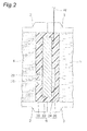
Fig. 2 is a magnified view of section II ofFig. 1 . -
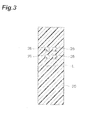
Fig. 3 is a schematic view showing a fabrication process for a membrane-electrode assembly comprising a hydrogenation device according to the second embodiment of the invention. -
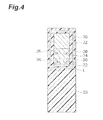
Fig. 4 is a schematic view showing a fabrication process for a membrane-electrode assembly comprising a hydrogenation device according to the second embodiment of the invention. -
Fig. 5 is a schematic view showing a fabrication process for a membrane-electrode assembly comprising a hydrogenation device according to the second embodiment of the invention. -
Fig. 6 is a schematic view of the oxidizing electrode side of a membrane-electrode assembly comprising a hydrogenation device according to the second embodiment of the invention. -
Fig. 7 is a schematic view of the reducing electrode side of a membrane-electrode assembly comprising a hydrogenation device according to the second embodiment of the invention. -
Fig. 8 is a photograph of a hot press machine used in a hot press step carried out during the fabrication process for the membrane-electrode assembly used in an example of the invention. -
Fig. 9 is a photograph of the membrane-electrode assembly used in the example of the invention. -
Fig. 10 is a graph showing conducting time between the oxidizing electrode and reducing electrode, current, and integrated electric charge calculated from the integrated value of the current, for the example of the invention. -
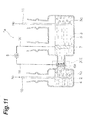
Fig. 11 is a simplified cross-sectional view of an organic compound hydrogenation device according to the first embodiment of the invention. -
Fig. 12 is a magnified view of section XII ofFig. 11 . - Preferred embodiments of the invention will now be described in detail. However, the present invention is not limited to the embodiments described below. Identical or similar parts will be indicated by like reference numerals. Also, the dimensional proportions depicted in the drawings are not necessarily limitative.
- According to the first embodiment, the
hydrogenation device 1a illustrated inFigs. 11 and12 is used for hydrogenation of an unsaturated compound(s) 4 (an organic compound(s) with unsaturated bonds). Hydrogenation of the unsaturated compound(s) 4 may be carried out, for example, in an ordinary temperature, ordinary pressure environment. - The
hydrogenation device 1a comprises areduction chamber 2, anoxidation chamber 3, and a membrane-electrode assembly 6a partitioning thereduction chamber 2 andoxidation chamber 3. Thereduction chamber 2 andoxidation chamber 3 are connected via the membrane-electrode assembly 6a. - Water or a water-containing supporting
electrolyte 5 is present in theoxidation chamber 3. The supportingelectrolyte 5 used may be one that is stable in terms of oxidation-reduction potential, and that has the necessary proton conductivity. For example, the supportingelectrolyte 5 used may be a solid polymer electrolyte membrane imbibed with an aqueous sodium sulfate solution, dilute sulfuric acid and water. If necessary, an inert gas such as nitrogen may be supplied into the supportingelectrolyte 5 from the exterior, through agas tube 11. - The oxidizing
electrode 7 is situated in the supportingelectrolyte 5 of theoxidation chamber 3. The oxidizingelectrode 7 is composed of an oxidation active component, and it has the function of generating protons and oxygen from water. The oxidation active component may be a precious metal, transition element, oxide, nitride, sulfide, selenide, oxynitride, thionitride or the like. Of these, precious metals are preferred from the viewpoint of stability under a strongly acidic atmosphere. Precious metals include platinum (Pt), palladium (Pd), rhodium (Rh), ruthenium (Ru), iridium (Ir) and osmium (Os). Preferred among these as active components are Pt, Rh and Ir, from the viewpoint of activity and selectivity. Transition elements include titanium (Ti), vanadium (V), chromium (Cr), manganese (Mn), iron (Fe), cobalt (Co), nickel (Ni), copper (Cu), zirconium (Zr), niobium (Nb), molybdenum (Mo), silver (Ag) and lanthanum (La). Catalysts having the aforementioned oxidation active components supported on an appropriate support are also preferred as constituent materials for the oxidizingelectrode 7. The support may be one with electrical conductivity, composed of a material with a large surface area. Preferred are active carbon, carbon nanotubes, carbon nanohoms and the like, from the viewpoint of ensuring electrical conductivity and a three-phase boundary. There is no need for the entire oxidizingelectrode 7 to be immersed in the supportingelectrolyte 5, and it is sufficient if contact between theelectrolyte 5 and the oxidizingelectrode 7 is ensured. - The unsaturated compound(s) 4 (preferably a liquid unsaturated compound(s) 4) is present in the
reduction chamber 2. To prevent inclusion of oxygen into thereduction chamber 2, if necessary an inert gas such as nitrogen may be supplied into the unsaturated compound(s) 4 from the exterior, through thegas tube 10. - The membrane-
electrode assembly 6a has anelectron collector layer 22, a reducingelectrode 24 and anelectrolyte membrane 20 layered in that order. Theelectron collector layer 22 contacts with the unsaturated compound(s) 4 present in thereduction chamber 2. Theelectrolyte membrane 20 contacts with the water-containing supportingelectrolyte 5 present in theoxidation chamber 3. The reducingelectrode 24 is sandwiched between theelectrolyte membrane 20 and theelectron collector layer 22, and contacts with theelectrolyte membrane 20 and theelectron collector layer 22. Preferably, the reducingelectrode 24 is in close contact with theelectrolyte membrane 20 and theelectron collector layer 22. - The
electrolyte membrane 20 is ion-permeable (preferably with proton conductivity). Theelectrolyte membrane 20 has a function of preventing mixture between the supportingelectrolyte 5 in theoxidation chamber 3 and the unsaturated compound(s) 4 in thereduction chamber 2. Theelectrolyte membrane 20 may be a solid polymer membrane, a fluorine resin-based ion exchange membrane or a membrane comprising a liquid with ionic conductivity (such as an ionic liquid, sulfuric acid or phosphoric acid) impregnated in the pores of a porous ceramic membrane. The solid polymer membrane may be a perfluorosulfonic acid-based proton-exchange membrane, among which NAFION membranes (registered trademark of DuPont Corp.) is preferred from the viewpoint of the ion permeation rate. The thickness of the solid polymer membrane will differ depending on the conditions, but it is preferably 10 to 500 µm from the viewpoint of hydrogen ion permeability and mechanical strength. The fluorine resin-based ion exchange membrane may be an Aciplex membrane (registered trademark of Asahi Kasei Corp.) or a Flemion membrane (registered trademark of Asahi Glass Co., Ltd.). - The amount of ion-exchange groups on the solid polymer membrane, i.e. the ion-exchange capacity (IEC), is preferably 0.1 to 3.0 meq/g from the viewpoint of the ion-exchange rate and stability, and even more preferably 0.3 to 2.0 meq/g from the viewpoint of durability. When a NAFION membrane is employed as the solid polymer membrane, for example, the amount of ion-exchange groups on the solid polymer membrane is the number of moles of sulfonic acid groups per 1 g of dry NAFION. The term "meq" stands for milli-equivalents. The ion-exchange capacity of a NAFION membrane is generally 1.0 meq/g.
- The
electron collector layer 22 is composed of a material having conductivity and voids. Theelectron collector layer 22 may be, for example, carbon paper or carbon cloth. The voids in theelectron collector layer 22 are constructed in such a manner as to ensure pathways through which the unsaturated compound(s) 4 can access the reducingelectrode 24, and the hydride of the unsaturated compound(s) 4 can diffuse into thereduction chamber 2. - The reducing
electrode 24 comprises a reduction active component, and it has a function of hydrogenating (reducing) the unsaturated compound(s) 4. The reduction active component may be a precious metal such as Pt, Pd or Ru, or a base metal such as Ni. Also, a catalyst having any of the aforementioned reduction active components supported on an appropriate support is preferred as the constituent material of the reducingelectrode 24. The support may be one composed of a material with electrical conductivity and having a large surface area (for example, about 100 m2/g), among which active carbon, carbon nanotubes, carbon nanohoms and carbon paper are preferred from the viewpoint of dispersibility of the reduction active component. - For this embodiment, the oxidizing
electrode 7 is connected to a direct current (DC)power supply 8 via a conductor wire W. The reducingelectrode 24 is connected to theDC power supply 8 via theelectron collector layer 22 and a conductor wire W. TheDC power supply 8 may be, for example, a renewable energy generator such as a solar photovoltaic power generator, a wind power generator, a hydroelectric power generator, a geothermal power generator or a tidal power generator. TheDC power supply 8 may also be combined with a rectifier. The reducingelectrode 24 for this embodiment is connected to theDC power supply 8 via theelectron collector layer 22 and the conductor wire W, but there is no limitation to this construction, and for example, the conductor wire W may be directly connected to the reducingelectrode 24 without passing through theelectron collector layer 22. - In the
hydrogenation device 1a according to the first embodiment, application of a voltage between the oxidizingelectrode 7 and the reducingelectrode 24 using theDC power supply 8 causes the electric potential at the oxidizingelectrode 7 to be higher than the reducingelectrode 24, and the oxygen ions (O2-) from water are oxidized on the surface of the oxidizingelectrode 7, generating oxygen while also generating protons from the water. The protons generated inside theoxidation chamber 3 migrate to the membrane-electrode assembly 6a by the difference in the electric potential between the oxidizingelectrode 7 and the reducingelectrode 24, passing through theelectrolyte 20 and reaching the reducingelectrode 24. On the other hand, the unsaturated compound(s) 4 in thereduction chamber 2 passes through theelectron collector layer 22 and reaches the reducingelectrode 24. Also, the unsaturated compound(s) 4 is hydrogenated (reduced) by the protons that have reached the reducingelectrode 24 and electrons supplied from the reducingelectrode 24, being converted to an organic hydride. - Thus, in the
hydrogenation device 1a according to the first embodiment, oxygen is generated at the oxidizingelectrode 7, while electrons supplied to the reducingelectrode 24 from the oxidizingelectrode 7 and protons generated inside theoxidation chamber 3 react with the unsaturated compound(s) 4, resulting in hydrogenation of the unsaturated compound(s) 4. In other words, in thehydrogenation device 1 a according to the first embodiment, it is possible to add water-derived hydrogen to the unsaturated compound(s) 4 by using renewable energy as an energy source to form an organic hydride, essentially without generating hydrogen gas by electrolysis of water. - The hydrogenation reaction of the organic compound(s) according to the first embodiment can be represented by the following chemical reaction formula (1).

- In formula (1), U(n) represents the unsaturated compound(s), n is an integer of 1 or greater representing the number of unsaturated bonds in U(n), x is an integer of between 1 and n, U(n-x) represents U(n) with 2x hydrogens added, and n-x is an integer representing the number of unsaturated bonds in U(n-x). When U(n) has been completely hydrogenated, x is equal to n, and U(n-x) is U(0), i.e. the compound(s) is free of unsaturated bonds.
- The value of ΔH (change in reaction enthalpy) in the electrolysis reaction of water represented by the following formula (2) is 285.8 kJ/mol, and the minimum applied voltage Vmin between the oxidizing electrode and reducing electrode required for the water electrolysis reaction is 1.23 Volt. On the other hand, as shown in Table 1, ΔH in the hydrogenation reaction of the liquid unsaturated compound(s) according to the first embodiment is smaller than ΔH in the water electrolysis reaction. In addition, the minimum applied voltage Vmin between the oxidizing electrode and reducing electrode required for hydrogenation reaction of the unsaturated compound(s) for the first embodiment is lower than the 1.23 Volt in the water electrolysis reaction. That is, in the
hydrogenation device 1a according to the first embodiment, hydrogenation of organic compounds can be carried out at lower energy (low applied voltage) compared to water electrolysis reaction. The values of ΔH and minimum applied voltage in the water electrolysis reaction and the hydrogenation reaction shown in Table 1 are the values assuming a reaction system temperature of 25°C. The H2O in formula (2) is liquid, and H2 and O2 are gases. The ΔH values in Table 1 are the changes in reaction enthalpy of the hydrogenation reaction of the unsaturated compounds, averaged by the number of hydrogen pairs added to the unsaturated compound(s). The unsaturated compounds and hydrides listed in Table 1 are all liquids.
-
[Table 1] Unsaturated compound Hydrogenated compound ΔH (kJ/mol·2H) Vmin (Volt) Toluene Methylcyclohexane 220.1 1.08 Benzene Cyclohexane 220.0 1.06 Naphthalene Decalin 222.6 1.09 Acetone Isopropyl alcohol 215.3 1.10 - In the
hydrogenation device 1a according to the first embodiment, it is possible to fix renewable energy as chemical substances in a more efficient manner than the prior art, since it requires essentially no generation of hydrogen gas by water electrolysis. Consequently, in thehydrogenation device 1a according to the first embodiment, it is not necessary to provide a reactor for generation of hydrogen gas by water electrolysis, separately from the reactor for hydrogenation. In addition, in thehydrogenation device 1a according to the first embodiment, the unsaturated compound(s) (organic hydride) which is a liquid under operating conditions can be utilized as an energy carrier (hydrogen carrier), and hence there is virtually no energy loss during transfer between organic hydride containers, and there is no need to use an apparatus for compression or liquefaction, unlike compressed hydrogen or liquefied hydrogen. In other words, thehydrogenation device 1a according to the first embodiment reduces the energy loss that occurs with storage and transport of electric power, and allows the apparatus to be downsized, compared to the prior art. - In the
hydrogenation device 1a according to the first embodiment, partitioning theoxidation chamber 3 andreduction chamber 2 with the membrane-electrode assembly 6a allows separation and extraction of the hydride of the unsaturated compound(s) 4, when the hydride has been produced at high yield in thereduction chamber 2. - Conventional hydrogenation of unsaturated compounds using high-pressure hydrogen gas has required many devices including a compressor, heat exchanger, distillation column and gas-liquid separator. Thus, a small-sized hydrogenation device is economically disadvantageous, while larger-sized apparatuses are more advantageous. On the other hand, since renewable energy originally has low energy density, electric power generation plants that utilize renewable energy are on a trend toward smaller sizes. Therefore, it is preferred for renewable energy storage devices to likewise be easily down-sizable. In this regard, since the
hydrogenation device 1a according to the first embodiment that does not employ high-pressure hydrogen gas can have a simple structure and be provided on a small scale, it is easily suited as a storage device for renewable energy. - For the purpose of the first embodiment, an organic compound(s) with unsaturated bonds is an organic compound(s) that has one or more double bonds or triple bonds in the molecule and that is liquid at ordinary temperature, ordinary pressure. Examples of double bonds include carbon-carbon double bonds, carbon-nitrogen double bonds, carbon-oxygen double bonds and nitrogen-oxygen double bonds, such as C=C, C=N, C=O and N=O. Examples of triple bonds include carbon-carbon triple bonds and carbon-nitrogen triple bonds. The organic compound(s) with unsaturated bonds is preferably a liquid organic compound(s) from the viewpoint of storage properties and transport properties.
- Examples of unsaturated compounds include olefins, dienes, acetylenes and aromatic compounds. Examples of aromatic compounds include aromatic compounds with 3- to 14-membered rings (usually aromatic compounds with six-membered rings), polycyclic aromatic compounds having multiple fused aromatic rings, aromatic compounds with substituents such as alkyl groups, and aromatic compounds including hetero atoms such as N. The aromatic compound is preferably a liquid aromatic compound(s).
- Specific examples of unsaturated compounds include olefins, dienes, acetylenes, benzene, carbon chain-substituted aromatic compounds, hetero-substituted aromatic compounds, polycyclic aromatic compounds, Schiff bases, hetero aromatic compounds, hetero 5-membered ring compounds, quinones, ketones and the like. Olefins include ethylene, propylene, butene, pentene, hexene, heptene, octene, nonene, decene, undecene, dodecene and the like. Dienes include arenes, butadiene, pentadiene, hexadiene, heptadiene, octadiene, piperylene, isoprene and the like. Acetylenes include acetylene, propyne and vinylacetylene. Carbon chain-substituted aromatic compounds include alkyl-substituted aromatic compounds. Alkyl-substituted aromatic compounds include toluene, xylene, trimethylbenzene, ethylbenzene, cumene and benzoic acid. Hetero-substituted aromatic compounds include anisole, dimethoxybenzene, phenol, aniline and N,N-dimethylaniline. Polycyclic aromatic compounds include naphthalene, methylnaphthalene, anthracene, tetracene, phenanthrene, tetralin and azulene. Schiff bases include 2-aza-hept-1-en-1-yl-cyclohexane. Hetero aromatic compounds include pyridine, pyrimidine, quinoline and isoquinoline. Hetero 5-membered ring compounds include furan, thiophene, pyrrole and imidazole. Quinones include benzoquinone and naphthoquinone. Ketones include acetone and methyl ethyl ketone. Needless to mention, carbon dioxide and carbon monoxide have unsaturated bonds but are generally not considered to be organic compounds, and these are therefore excluded from the unsaturated compounds according to the first embodiment.
- Of these aforementioned unsaturated compounds, benzene, toluene, xylene, ethylbenzene, naphthalene, methylnaphthalene and tetralin (hereunder also referred to as "benzenes") are water-insoluble before and after hydrogenation, and phase separable with water, and therefore they are more preferred over water-soluble organic compounds such as acetone, in that they can be very easily recovered as products. For the same reason, the unsaturated compound(s) 4 and the hydrogenation product (hydride of the unsaturated compound(s) 4) in the
reduction chamber 2 are preferably both present as liquids. These benzenes may be used as the pure compounds, or as mixtures of multiple compounds. - The benzenes are hydrogenated in the
reduction chamber 2, but preferably control is conducted during operation of thehydrogenation device 1a to minimize the presence of liquid water in thereduction chamber 2, from the viewpoint of limiting reduction in activity of the hydrogenation catalyst in the MEA. - As explained below, the unsaturated compound(s) 4 is converted to the reduced compound(s) (organic hydride) as its unsaturated bonds are hydrogenated by the water-derived hydrogen in the reducing
electrode 24. That is, according to the invention it is possible to store hydrogen in the form of an organic hydride. In this hydrogenation, it is not necessary for all of the unsaturated bonds of the unsaturated compound(s) to be reduced. For example, naphthalene may be reduced to tetralin, and benzoquinone may be reduced to hydroquinone. - The unsaturated compound(s) 4 in the
hydrogenation reactor 1a is preferably in a liquid state. In other words, hydrogenation of the unsaturated compound(s) 4 is conducted in a liquid state. This eliminates the need for a vaporizer, condenser or the like, and allows the equipment to be downsized. For the same reason, the unsaturated compound(s) 4 and the hydrogenation product in thereduction chamber 2 are preferably both present as liquids. - After transporting the reduced compound(s) of the unsaturated compound(s) to a desired location as a hydrogen storage substance, it is used as an energy source and converted to mechanical power or electric power. There are no particular restrictions on the usage of the reduced compound(s), and for example, the reduced compound(s) may be used as a starting material for generation of hydrogen. Specifically, methods exist for obtaining electric power from fuel cells wherein the fuel is hydrogen obtained by dehydrogenation of the reduced compound(s), in the presence of an appropriate catalyst (see Ichikawa, Nenryo Denchi, Vol. 1(2), 44(2001), for example). Methods also exist using reduced compounds directly as fuels for fuel cells (see Physical Chemistry Chemical Physics, 8, 1724-1730(2006), Z. Shi, J. Power Sources, 176, 122-127(2008),
USP2008/0152960 , for example). - The oxygen produced during hydrogenation of the unsaturated compound(s) may be consumed by any desired method, such as in assisted respiration, as a combustion aid or as a chemical starting material, or it may be released into the atmosphere.
- In the prior art, hydrogen gas has been synthesized by electrolysis of water using electric power obtained from renewable energy, such as solar photovoltaic power generation, or by photodecomposition of water. In addition, hydrogen gas has been converted into the form of liquefied hydrogen or compressed hydrogen in the prior art, for storage and transport. However, liquefied hydrogen must be held at cryogenic temperature, and compressed hydrogen must be held under high pressure. Thus, storage and transportation of renewable energy in the form of liquefied hydrogen or compressed hydrogen are associated with high energy loss and large equipment sizes. In the hydrogenation method according to the first embodiment, however, renewable energy is converted to the form of an organic hydride storing hydrogen. Organic hydrides exist as more stable liquids at ordinary temperature, ordinary pressure, compared to hydrogen, and therefore their storage and transport are easier. Thus, the hydrogenation method according to the first embodiment produces organic hydrides as clean, high energy substances derived from renewable energy sources in regions that are rich in renewable energy but very far from energy consumption areas, and allows them to be easily stored and transported to consumption areas.
- An
electrolyte membrane 20 was attached to the reducingelectrode 24 side of anelectron collector layer 22 having a reducingelectrode 24 formed on one side thereof, and was pressed while heating by a hot press method, to obtain a membrane-electrode assembly 6a. Using the hot press method results in airtight attachment inside the membrane-electrode assembly 6a. The steps of connecting the conductor wire W andcollector layer 22 may be carried out either before or after the hot press method. - A
hydrogenation device 1 according to the second embodiment of the invention, illustrated inFig. 1 andFig. 2 , and a hydrogenation method for an unsaturated compound(s) 4 using thedevice 1, will now be described. Thehydrogenation device 1 according to the second embodiment is similar to thehydrogenation device 1a according to the first embodiment, except that it employs a membrane-electrode assembly 6 as illustrated inFigs. 1 ,2 ,6 and7 , instead of the membrane-electrode assembly 6a shown inFig. 11 andFig. 12 used in thehydrogenation device 1a according to the first embodiment. Aspects of the membrane-electrode assembly 6 of thehydrogenation device 1 according to the second embodiment will now be explained. Aspects that are common to thehydrogenation device 1a according to the first embodiment and thehydrogenation device 1 according to the second embodiment will not be explained. The membrane-electrode assembly 6 of thehydrogenation device 1 according to the second embodiment has higher adhesiveness (airtightness) between theelectron collector layer 22, reducingelectrode 24 andelectrolyte membrane 20, and more excellent mechanical strength, compared to the membrane-electrode assembly 6a of thehydrogenation device 1a according to the first embodiment. Thus, thehydrogenation device 1 according to the second embodiment can easily prevent mixture between the contents of the reduction chamber 2 (the unsaturated compound(s) 4 or its hydride) and theelectrolyte 5 in the reducingelectrode 24. - The membrane-
electrode assembly 6 comprises anelectron collector layer 22, a reducingelectrode 24 and anelectrolyte membrane 20. The reducingelectrode 24 is formed on the side of the surface of theelectron collector layer 22 that is facing theelectrolyte 5 inside the oxidation chamber 3 (the facing surface). Theelectrolyte membrane 20 covers theelectron collector layer 22 and reducingelectrode 24, and contacts with theelectron collector layer 22 and reducingelectrode 24. Preferably, theelectrolyte membrane 20 is in close contact with theelectron collector layer 22 and the reducingelectrode 24. -
Openings 26 are formed on a section of theelectrolyte membrane 20 located on the side opposite from the reducingelectrode 24 sandwiching theelectron collector layer 22. Theopenings 26 face the interior of thereduction chamber 2. The back side of the section of theelectron collector layer 22 on which the reducingelectrode 24 has been formed (the section opposite from the reducing electrode 24) alone is exposed through theopenings 26. Theelectron collector layer 22 exposed through the opening 26 contacts with the unsaturated compound(s) 4 inside thereduction chamber 2. Theopenings 26 function as inlets for the saturated compound(s) 4. - In the
hydrogenation device 1 according to the second embodiment, application of a voltage between the oxidizingelectrode 7 and the reducingelectrode 24 using thepower supply 8 causes the electric potential at the oxidizingelectrode 7 to be higher than the reducingelectrode 24, and the oxygen ions (O2-) from water are oxidized on the surface of the oxidizingelectrode 7, generating oxygen while also generating protons from the water. The protons generated inside theoxidation chamber 3 migrate to the membrane-electrode assembly 6 by the difference in the electric potential between the oxidizingelectrode 7 and the reducingelectrode 24, passing through theelectrolyte 20 and reaching the reducingelectrode 24. On the other hand, the unsaturated compound(s) 4 in thereduction chamber 2 passes through theelectron collector layer 22 via theopenings 26, and reaches the reducingelectrode 24. Also, the unsaturated compound(s) 4 is hydrogenated (reduced) by the protons that have reached the reducingelectrode 24 and electrons supplied from the reducingelectrode 24. - Thus, in the
hydrogenation device 1 according to the second embodiment, oxygen is generated at the oxidizingelectrode 7, while electrons supplied to the reducingelectrode 24 from the oxidizingelectrode 7 and protons generated inside theoxidation chamber 3 react with the unsaturated compound(s) 4, resulting in hydrogenation of the unsaturated compound(s) 4. In other words, in thehydrogenation device 1 according to the second embodiment, it is possible to add water-derived hydrogen directly to the unsaturated compound(s) 4 by using renewable energy as an energy source to form an organic hydride, essentially without generating hydrogen gas by electrolysis of water. - As shown in
Fig. 3 ,openings 26 are formed in alongitudinal electrolyte membrane 20. As shown inFig. 4 , theelectron collector layer 22 having the reducingelectrode 24 formed on one side thereof is situated on one half of theelectrolyte membrane 20, and theelectron collector layer 22 and reducingelectrode 24 overlap entirely over theopenings 26. Abonding agent 30 is coated onto theelectrolyte membrane 20, surrounding theelectron collector layer 22. As shown inFig. 4 andFig. 5 , when theelectrolyte membrane 20 is folded along a folding line L dividing theelectrolyte membrane 20 in half in the longitudinal direction, and attached, theelectron collector layer 22, reducingelectrode 24 andbonding agent 30 become sandwiched by theelectrolyte membrane 20. The foldedelectrolyte membrane 20 is pressed while heating by a hot press method, to obtain a membrane-electrode assembly 6. Using the hot press method results in airtight attachment inside the membrane-electrode assembly 6. The steps of connecting the conductor wire W andcollector layer 22 may be carried out either before or after the hot press method. - The present invention will now be explained in greater detail through the following examples, with the understanding that these examples are in no way limitative on the invention.
- As shown in
Fig. 3 , fouropenings 26 were formed in alongitudinal electrolyte membrane 20. The dimensions of theopenings 26 were 0.5 cm × 0.5 cm. Theelectrolyte membrane 20 used was a NAFION membrane, imbibed with a 5% Nafion suspension. The dimensions of theelectrolyte membrane 20 were 2.5 cm × 7.0 cm. The thickness of theelectrolyte membrane 20 was 178 µm (0.007 inch). - As shown in
Fig. 4 , theelectron collector layer 22 having the reducingelectrode 24 coated and formed on one side thereof, was situated on one half of theelectrolyte membrane 20, and theelectron collector layer 22 and reducingelectrode 24 were overlapped over theentire opening 26. Theelectron collector layer 22 having the reducingelectrode 24 coated and formed on one side thereof was a fuel cell electrode (product of Chemix, Inc.). Theelectron collector layer 22 of the fuel cell electrode was made of carbon paper. The reducingelectrode 24 was Pt supported on carbon black (hereunder referred to as "Pt/C catalyst"). The platinum loading weight with respect to the carbon paper was 2.0 g/cm2. - As shown in
Fig. 4 , abonding agent 30 was coated onto theelectrolyte membrane 20, surrounding theelectron collector layer 22. Thebonding agent 30 used was an epoxy-based bonding agent. - As shown in
Fig. 4 andFig. 5 , theelectrolyte membrane 20 was folded along the folding line L, sandwiching theelectron collector layer 22, reducingelectrode 24 andbonding agent 30, and the foldedelectrolyte membrane 20 was pressed while heating by a hot press method. A hot press machine as shown inFig. 8 was used for the hot press method. In the hot press method, the foldedelectrolyte membrane 20 was heated at 130°C while applying a pressure of 23 MPa onto theelectrolyte membrane 20 for 1 minute. - After carrying out the hot press method, a section of the
electrolyte membrane 20 was cut out, a conductor wire W was connected to theelectron collector layer 22, and the cut section was sealed with an epoxy-based bonding agent to obtain aMEA 4 as a membrane-electrode assembly 6 (seeFigs. 2 ,6 ,7 and9 ). - A
hydrogenation device 1 as illustrated inFig. 1 andFig. 2 was fabricated. A 100 ml of 0.1 M H2SO4 aqueous solution was used as the supportingelectrolyte solution 5 in theoxidation chamber 3. Also, 4 ml of toluene (product of Wako Corp., purity: 99.8%) was used as the liquid unsaturated compound(s) 4 in thereduction chamber 2. No liquid water was found in thereduction chamber 2 during this time. A Pt wire was used as the oxidizingelectrode 7. TheMEA 4 described above was used as the membrane-electrode assembly 6. - After applying an electric potential of -0.3 VRHE, using an electrochemical measuring system (potentiostat) for 108 hours, between the oxidizing
electrode 7 and reducingelectrode 24 of thehydrogenation device 1 comprising theMEA 4, an electric potential of-1.24 VRHE was applied for 17 hours. The electrochemical measuring system used was an HZ-5000 by Hokuto Denko Corp. - During application of the electric potential, generation of oxygen gas from the surface of the oxidizing
electrode 7 was visually confirmed. Lack of generation of air bubbles (hydrogen gas) in thereduction chamber 2 was also visually confirmed during application of the electric potential. - Changes in the current value between the oxidizing
electrode 7 and the reducingelectrode 24 were also monitored during application of the electric potential, using an electrochemical measuring system (Model HZ-5000 by Hokuto Denko Corp.). Flow of current was confirmed, as a result, as indicated by the solid line inFig. 10 . - After completing 125 hours of application of the potential, the unsaturated compound(s) 4 in the
reduction chamber 2 was subjected to gas chromatography analysis with a gas chromatograph (Model: GC-2014 by Shimadzu Corp.). - Conditions for the gas chromatography analysis were as follows.
- Column: J&W SCIENTIFIC CATALOG 1223232, DB-FFAP 30 m 0.25 nm 0.25U
- Mobile phase: Nitrogen
- Injection volume: 3 µL
- Flow rate: 2.84 mL/min
- Methylcyclohexane retention time: 1.4 minutes
- Toluene retention time: 4.5 minutes
- As a result of quantification by the gas chromatography analysis, 5.1 × 10⁻³ mol of methylcyclohexane (reduction rate: 13.7%) was confirmed to be produced in the toluene in the
reduction chamber 2. The integrated electric charge, determined from the change in the current integrated value (broken line shown inFig. 10 ), was 4.3 × 10⁻³ mol (reduction rate: 11.5%). Despite some differences in the integrated electric charge and methylcyclohexane production amount, this may be considered to be a high degree of matching between them, taking into account the measuring precision. - Thus, in the examples using the
MEA 4 , it was confirmed that application of a electric potential between the oxidizingelectrode 7 and reducingelectrode 24 generates oxygen at the oxidizingelectrode 7 while hydrogenating toluene at the MEA 4 (membrane-electrode assembly 6) comprising the reducingelectrode 24, generating methylcyclohexane. - According to the invention it is possible to store hydrogen essentially without generating hydrogen gas, and therefore the present invention is suitable for fixing and storage of hydrogen using renewable energy generators, such as solar photovoltaic power generators, wind power generators, hydroelectric power generators, geothermal power generators and tidal power generators.
- 1, 1a: Hydrogenation devices, 2: reduction chamber, 3: oxidation chamber, 4: liquid organic compound(s) with unsaturated bond, 5: water-containing supporting electrolyte, 6, 6a: membrane-electrode assemblies, 7: oxidizing electrode, 8: DC power supply, 20: electrolyte membrane, 22: collector layer, 24: reducing electrode, 26: opening, 10, 11: gas tube.
Claims (11)
- An organic compound(s) hydrogenation device comprising:an oxidation chamber that holds a water-containing electrolyte,a reduction chamber that holds an organic compound(s) with an unsaturated bond,an electrolyte membrane with ion permeability, separating the electrolyte held in the oxidation chamber from the organic compound(s) held in the reduction chamber,an oxidizing electrode that generates protons from the water held in the oxidation chamber, anda reducing electrode that hydrogenates the organic compound(s) held in the reduction chamber.
- An organic compound(s) hydrogenation device comprising:an oxidation chamber that holds a water-containing electrolyte,a reduction chamber that holds an organic compound(s) with an unsaturated bond,a proton conductive electrolyte membrane separating the interior of the oxidation chamber from the interior of the reduction chamber,an oxidizing electrode situated in the oxidation chamber, anda reducing electrode adjacent to the electrolyte membrane, contacting with the organic compound(s) in the reduction chamber to hydrogenate the organic compound(s).
- The organic compound(s) hydrogenation device according to claim 1 or 2, comprising a membrane-electrode assembly having an electron collector layer that allows permeation of the organic compound(s), the reducing electrode, and the electrolyte membrane,
wherein the reducing electrode is situated between the electron collector layer and the electrolyte membrane,
the electrolyte membrane covers the electron collector layer and the reducing electrode, and has an opening exposing the section of the side of the electron collector layer opposite the reducing electrode. - The organic compound(s) hydrogenation device according to claim 1 or 2, comprising a membrane-electrode assembly having an electron collector layer that allows permeation of the organic compound(s), the reducing electrode being formed on one side of the electron collector layer, and the electrolyte membrane covering the electron collector layer and the reducing electrode,
wherein an opening is formed on a section of the electrolyte membrane located on the side opposite the reducing electrode sandwiching the electron collector layer,
the opening faces the inside of the reduction chamber, and
the back side of the section of the electron collector layer on which the reducing electrode has been formed is exposed through the opening. - The organic compound(s) hydrogenation device according to any one of claims 1 to 4, comprising a power source that applies a voltage to the oxidizing electrode and the reducing electrode.
- The organic compound(s) hydrogenation device according to claim 5, comprising:a conductor wire that connects the oxidizing electrode and the power source, anda conductor wire that connects the reducing electrode and the power source.
- An organic hydrogenation method employing a hydrogenation device according to any one of claims 1 to 6, wherein:a voltage is applied to the oxidizing electrode and the reducing electrode through the conductor wires, causing generation of oxygen at the oxidizing electrode and hydrogenation of the organic compound(s) at the reducing electrode.
- The organic hydrogenation method according to claim 7, wherein the organic compound(s) is at least one selected from the group consisting of benzene, toluene, xylene, ethylbenzene, naphthalene, methylnaphthalene and tetralin.
- The organic hydrogenation method according to claim 7, wherein the organic compound(s) is a liquid hydrocarbon that undergoes phase separation with water.
- The organic hydrogenation method according to claim 7, wherein the organic and a hydride of the organic compound(s) in the reduction chamber are both present as liquids.
- The organic hydrogenation method according to claim 7, which maintains inclusion of water into the reduction chamber at a minimum.
Applications Claiming Priority (2)
| Application Number | Priority Date | Filing Date | Title |
|---|---|---|---|
| JP2010293684 | 2010-12-28 | ||
| PCT/JP2011/080487 WO2012091128A1 (en) | 2010-12-28 | 2011-12-28 | Organic compound hydrogenation device and hydrogenation method |
Publications (2)
| Publication Number | Publication Date |
|---|---|
| EP2660356A1 true EP2660356A1 (en) | 2013-11-06 |
| EP2660356A4 EP2660356A4 (en) | 2014-07-09 |
Family
ID=46383215
Family Applications (1)
| Application Number | Title | Priority Date | Filing Date |
|---|---|---|---|
| EP11854409.7A Withdrawn EP2660356A4 (en) | 2010-12-28 | 2011-12-28 | ORGANIC COMPOUND HYDROGENATION DEVICE AND HYDROGENATION METHOD |
Country Status (4)
| Country | Link |
|---|---|
| US (1) | US20130313127A1 (en) |
| EP (1) | EP2660356A4 (en) |
| JP (1) | JP5831913B2 (en) |
| WO (1) | WO2012091128A1 (en) |
Cited By (1)
| Publication number | Priority date | Publication date | Assignee | Title |
|---|---|---|---|---|
| CN106133199A (en) * | 2014-03-28 | 2016-11-16 | 国立大学法人横浜国立大学 | Organic hydride material producing device |
Families Citing this family (25)
| Publication number | Priority date | Publication date | Assignee | Title |
|---|---|---|---|---|
| WO2015005280A1 (en) * | 2013-07-09 | 2015-01-15 | 学校法人早稲田大学 | Hydrogen carrier and hydrogen generation method |
| EP3029177B1 (en) * | 2013-07-30 | 2019-03-20 | JX Nippon Oil & Energy Corporation | Electrochemical reduction apparatus, and production method for hydrogenated aromatic compound |
| JP6400410B2 (en) | 2014-09-25 | 2018-10-03 | 国立大学法人横浜国立大学 | Electrolysis cell for organic chemical hydride production |
| US10889903B2 (en) | 2014-11-10 | 2021-01-12 | National University Corporation Yokohama National University | Oxygen-generating anode |
| JP6501141B2 (en) | 2014-11-21 | 2019-04-17 | 国立大学法人横浜国立大学 | Organic hydride manufacturing apparatus and method of manufacturing organic hydride using the same |
| JP2016204701A (en) * | 2015-04-21 | 2016-12-08 | Jxエネルギー株式会社 | Hydrogenation reaction system of aromatic compound |
| JP6758628B2 (en) | 2016-11-15 | 2020-09-23 | 国立大学法人横浜国立大学 | Organic hydride manufacturing equipment and organic hydride manufacturing method |
| JP6954561B2 (en) | 2017-05-23 | 2021-10-27 | 国立大学法人横浜国立大学 | Organic hydride manufacturing equipment |
| KR20190083546A (en) * | 2018-01-04 | 2019-07-12 | (주)엘켐텍 | Electrochemical hydrogenation reactor and method of hydrogenation using the same |
| JP6998797B2 (en) * | 2018-03-01 | 2022-02-10 | Eneos株式会社 | Organic hydride manufacturing equipment, organic hydride manufacturing method and energy transportation method |
| JP7372797B2 (en) | 2019-09-20 | 2023-11-01 | Eneos株式会社 | Organic hydride generation system and method for controlling the organic hydride generation system |
| JP7426817B2 (en) | 2019-12-26 | 2024-02-02 | Eneos株式会社 | Organic hydride generation system, control device for organic hydride generation system, and control method for organic hydride generation system |
| EP4257731A4 (en) | 2020-12-03 | 2025-04-23 | ENEOS Corporation | ORGANIC HYDRIDE PRODUCTION APPARATUS, WATER REMOVAL DEVICE AND WATER REMOVAL METHOD |
| CN116529425A (en) | 2020-12-04 | 2023-08-01 | 引能仕株式会社 | Organic hydride production device and method for recycling co-water |
| US12351923B2 (en) | 2020-12-04 | 2025-07-08 | Eneos Corporation | Organic hydride producing system, control device for organic hydride producing system, and control method for organic hydride producing system |
| EP4257730A4 (en) | 2020-12-04 | 2025-05-07 | ENEOS Corporation | ORGANIC HYDRIDE PRODUCTION SYSTEM, CONTROL DEVICE FOR ORGANIC HYDRIDE PRODUCTION SYSTEM, AND CONTROL METHOD FOR ORGANIC HYDRIDE PRODUCTION SYSTEM |
| WO2022176511A1 (en) | 2021-02-19 | 2022-08-25 | Eneos株式会社 | Apparatus for producing organic hydride and method for producing organic hydride |
| WO2023146457A2 (en) * | 2022-01-25 | 2023-08-03 | Ghorbani Shiraz Hamid | A method and device for electrochemical hydrogenation of liquid organic hydrogen carriers |
| EP4495294A4 (en) | 2022-03-17 | 2026-03-18 | Eneos Corp | DEVICE FOR THE PRODUCTION OF ORGANIC HYDRIDE |
| US20250198021A1 (en) | 2022-03-17 | 2025-06-19 | Eneos Corporation | Organic hydride production apparatus |
| US20260055520A1 (en) | 2022-08-29 | 2026-02-26 | Eneos Corporation | Apparatus for producing organic hydride and method for producing organic hydride |
| WO2025057732A1 (en) * | 2023-09-12 | 2025-03-20 | Agc株式会社 | Method for producing fluorine-containing polymer |
| AU2024402290A1 (en) * | 2023-12-20 | 2026-06-18 | Commonwealth Scientific And Industrial Research Organisation | Electrochemical reactions |
| WO2026100325A1 (en) * | 2024-11-11 | 2026-05-15 | 花王株式会社 | Organic compound production device and organic compound production method |
| CN119753703B (en) * | 2024-12-12 | 2025-10-31 | 中钢集团鞍山热能研究院有限公司 | Green hydrogenation method for crude anthracene by using electrochemical reactor |
Family Cites Families (14)
| Publication number | Priority date | Publication date | Assignee | Title |
|---|---|---|---|---|
| US3485726A (en) * | 1967-02-14 | 1969-12-23 | Mitsubishi Chem Ind | Method for electrohydrogenation of benzene and substituted derivatives thereof |
| JPS5245707B1 (en) * | 1973-04-16 | 1977-11-17 | ||
| JPS5245707A (en) * | 1975-08-13 | 1977-04-11 | Automob Antipollut & Saf Res Center | Driving circuit for plunger pump |
| JP2700052B2 (en) * | 1995-03-08 | 1998-01-19 | 工業技術院長 | Hydride production method |
| JP3561108B2 (en) * | 1997-01-07 | 2004-09-02 | ペルメレック電極株式会社 | Hydrogenation method and electrolytic cell |
| JP4850996B2 (en) * | 2000-04-28 | 2012-01-11 | パナソニック株式会社 | Electrode plate unit and battery |
| JP2003045449A (en) | 2001-08-01 | 2003-02-14 | Masaru Ichikawa | Chemical power generation / organic hydride manufacturing apparatus and chemical power generation / organic hydride manufacturing method |
| DE10148600A1 (en) * | 2001-10-02 | 2003-04-10 | Bayer Ag | Electrolyzer used for electrolyzing hydrochloric acid has gas diffusion electrodes fixed to current collector |
| US7276353B2 (en) | 2001-12-12 | 2007-10-02 | Virginia Tech Intellectual Properties, Inc. | Chimeric infectious DNA clones, chimeric porcine circoviruses and uses thereof |
| US6949178B2 (en) * | 2002-07-09 | 2005-09-27 | Lynntech, Inc. | Electrochemical method for preparing peroxy acids |
| JP2005126288A (en) | 2003-10-24 | 2005-05-19 | Toyota Motor Corp | Hydrogen storage / release device |
| JP2005239479A (en) | 2004-02-26 | 2005-09-08 | Toyota Motor Corp | Hydrogen gas separator and hydrogen gas generator |
| US8039167B2 (en) | 2006-12-20 | 2011-10-18 | Governors Of The University Of Alberta | Paraffin fuel cell |
| US8512907B2 (en) * | 2007-09-27 | 2013-08-20 | Dai Nippon Printing Co., Ltd. | Membrane catalyst layer assembly with reinforcing films, membrane electrode assembly with reinforcing films, and polymer electrolyte fuel cells |
-
2011
- 2011-12-28 US US13/976,689 patent/US20130313127A1/en not_active Abandoned
- 2011-12-28 EP EP11854409.7A patent/EP2660356A4/en not_active Withdrawn
- 2011-12-28 JP JP2012551057A patent/JP5831913B2/en active Active
- 2011-12-28 WO PCT/JP2011/080487 patent/WO2012091128A1/en not_active Ceased
Cited By (2)
| Publication number | Priority date | Publication date | Assignee | Title |
|---|---|---|---|---|
| CN106133199A (en) * | 2014-03-28 | 2016-11-16 | 国立大学法人横浜国立大学 | Organic hydride material producing device |
| US10202698B2 (en) | 2014-03-28 | 2019-02-12 | Yokohama National University | Device for manufacturing organic hydride |
Also Published As
| Publication number | Publication date |
|---|---|
| JP5831913B2 (en) | 2015-12-09 |
| WO2012091128A1 (en) | 2012-07-05 |
| EP2660356A4 (en) | 2014-07-09 |
| JPWO2012091128A1 (en) | 2014-06-05 |
| US20130313127A1 (en) | 2013-11-28 |
Similar Documents
| Publication | Publication Date | Title |
|---|---|---|
| US20130313127A1 (en) | Organic compound hydrogenation device and hydrogenation method | |
| JP5705214B2 (en) | Organic hydride production equipment | |
| JP6588090B2 (en) | Membrane / electrode assembly, reactor including the membrane / electrode assembly, and method for separating hydrogen | |
| KR101417354B1 (en) | Film electrode-bond and organic hydride manufacturing apparatus | |
| EP3031955A1 (en) | Hydrogen refining pressure-boosting device | |
| US20140144774A1 (en) | Device for manufacturing organic hydride | |
| US20140287347A1 (en) | Method for fabricating a membrane-electrode assembly | |
| JPWO2012128148A1 (en) | Carbon dioxide reduction and fixation system, carbon dioxide reduction and fixation method, and method for producing useful carbon resources | |
| JP6998797B2 (en) | Organic hydride manufacturing equipment, organic hydride manufacturing method and energy transportation method | |
| Li et al. | Design of bifunctional electrodes for co-generation of electrical power and hydrogen peroxide | |
| Ju et al. | Methanol-water co-electrolysis for sustainable hydrogen production with PtRu/C-SnO2 electro-catalyst | |
| AU2010316633B2 (en) | A hydrogen or oxygen electrochemical pumping catalytic membrane reactor and its applications | |
| KR20190083546A (en) | Electrochemical hydrogenation reactor and method of hydrogenation using the same | |
| JP5515145B2 (en) | Method for storing hydrogen generated by light energy | |
| WO2014192089A1 (en) | Device for producing organic hydride | |
| Bannert et al. | Transition Metal Carbide Electrocatalysts (WC, W2C, and Mo2C) Compared to Platinum in a Solid Acid Electrolysis Cell | |
| US20170149079A1 (en) | Nanocomposite electrode material for proton conducting electrochemical devices | |
| JP7105421B2 (en) | Epoxy Derivative Production Apparatus, Epoxy Derivative Production Method, and Epoxy Derivative Production Apparatus Production Method | |
| Murdoch et al. | Closed-Loop Hydrogen Recovery Enabled by Electrochemical Hydrogen Separation | |
| KR20190125885A (en) | Electrochemical dehydrogen reactor and method of dehydrogenation using the same | |
| WO2024034444A1 (en) | Apparatus for producing organic hydride | |
| Kim et al. | Carbon‐Neutralized Direct Methanol Fuel Cell Using Bifunctional (Methanol Oxidation/CO2 Reduction) Electrodes | |
| Shuihua et al. | Effect of methanol concentration on oxygen reduction reaction activity of Pt/C catalysts | |
| EP4621106A1 (en) | Electrolysis system and electrolysis device | |
| WO2024219065A1 (en) | Organic hydride production device and organic hydride production method |
Legal Events
| Date | Code | Title | Description |
|---|---|---|---|
| PUAI | Public reference made under article 153(3) epc to a published international application that has entered the european phase |
Free format text: ORIGINAL CODE: 0009012 |
|
| 17P | Request for examination filed |
Effective date: 20130726 |
|
| AK | Designated contracting states |
Kind code of ref document: A1 Designated state(s): AL AT BE BG CH CY CZ DE DK EE ES FI FR GB GR HR HU IE IS IT LI LT LU LV MC MK MT NL NO PL PT RO RS SE SI SK SM TR |
|
| DAX | Request for extension of the european patent (deleted) | ||
| A4 | Supplementary search report drawn up and despatched |
Effective date: 20140606 |
|
| RIC1 | Information provided on ipc code assigned before grant |
Ipc: C25B 3/04 20060101ALI20140602BHEP Ipc: C07C 5/10 20060101ALI20140602BHEP Ipc: C07C 13/18 20060101ALI20140602BHEP Ipc: C07B 61/00 20060101ALI20140602BHEP Ipc: C01B 3/00 20060101ALI20140602BHEP Ipc: C25B 9/00 20060101AFI20140602BHEP |
|
| 17Q | First examination report despatched |
Effective date: 20150709 |
|
| GRAP | Despatch of communication of intention to grant a patent |
Free format text: ORIGINAL CODE: EPIDOSNIGR1 |
|
| INTG | Intention to grant announced |
Effective date: 20160108 |
|
| STAA | Information on the status of an ep patent application or granted ep patent |
Free format text: STATUS: THE APPLICATION IS DEEMED TO BE WITHDRAWN |
|
| 18D | Application deemed to be withdrawn |
Effective date: 20160519 |