JP6501141B2 - Organic hydride manufacturing apparatus and method of manufacturing organic hydride using the same - Google Patents
Organic hydride manufacturing apparatus and method of manufacturing organic hydride using the same Download PDFInfo
- Publication number
- JP6501141B2 JP6501141B2 JP2014236772A JP2014236772A JP6501141B2 JP 6501141 B2 JP6501141 B2 JP 6501141B2 JP 2014236772 A JP2014236772 A JP 2014236772A JP 2014236772 A JP2014236772 A JP 2014236772A JP 6501141 B2 JP6501141 B2 JP 6501141B2
- Authority
- JP
- Japan
- Prior art keywords
- cathode
- hydride
- anode
- organic hydride
- organic
- Prior art date
- Legal status (The legal status is an assumption and is not a legal conclusion. Google has not performed a legal analysis and makes no representation as to the accuracy of the status listed.)
- Active
Links
- 150000004678 hydrides Chemical class 0.000 title claims description 102
- 238000004519 manufacturing process Methods 0.000 title claims description 46
- 238000005192 partition Methods 0.000 claims description 49
- 239000012528 membrane Substances 0.000 claims description 40
- 239000003054 catalyst Substances 0.000 claims description 36
- UFHFLCQGNIYNRP-UHFFFAOYSA-N Hydrogen Chemical compound [H][H] UFHFLCQGNIYNRP-UHFFFAOYSA-N 0.000 claims description 33
- 239000001257 hydrogen Substances 0.000 claims description 27
- 229910052739 hydrogen Inorganic materials 0.000 claims description 27
- 239000000047 product Substances 0.000 claims description 14
- 239000005518 polymer electrolyte Substances 0.000 claims description 10
- 239000007787 solid Substances 0.000 claims description 9
- XLYOFNOQVPJJNP-UHFFFAOYSA-N water Substances O XLYOFNOQVPJJNP-UHFFFAOYSA-N 0.000 claims description 7
- 239000006227 byproduct Substances 0.000 claims description 6
- 239000000203 mixture Substances 0.000 claims description 6
- 238000007599 discharging Methods 0.000 claims 1
- YXFVVABEGXRONW-UHFFFAOYSA-N Toluene Chemical compound CC1=CC=CC=C1 YXFVVABEGXRONW-UHFFFAOYSA-N 0.000 description 51
- 239000003792 electrolyte Substances 0.000 description 43
- 238000005868 electrolysis reaction Methods 0.000 description 24
- 125000006850 spacer group Chemical group 0.000 description 22
- 239000000758 substrate Substances 0.000 description 19
- 239000007788 liquid Substances 0.000 description 18
- 239000000463 material Substances 0.000 description 18
- UAEPNZWRGJTJPN-UHFFFAOYSA-N methylcyclohexane Chemical compound CC1CCCCC1 UAEPNZWRGJTJPN-UHFFFAOYSA-N 0.000 description 16
- 150000002894 organic compounds Chemical class 0.000 description 16
- 239000002994 raw material Substances 0.000 description 14
- OKTJSMMVPCPJKN-UHFFFAOYSA-N Carbon Chemical compound [C] OKTJSMMVPCPJKN-UHFFFAOYSA-N 0.000 description 13
- 230000002378 acidificating effect Effects 0.000 description 13
- 239000002245 particle Substances 0.000 description 13
- 229910052799 carbon Inorganic materials 0.000 description 12
- 238000000034 method Methods 0.000 description 12
- 238000006243 chemical reaction Methods 0.000 description 10
- 239000007789 gas Substances 0.000 description 8
- GYNNXHKOJHMOHS-UHFFFAOYSA-N methyl-cycloheptane Natural products CC1CCCCCC1 GYNNXHKOJHMOHS-UHFFFAOYSA-N 0.000 description 8
- 238000006722 reduction reaction Methods 0.000 description 8
- 230000000052 comparative effect Effects 0.000 description 7
- 239000000126 substance Substances 0.000 description 7
- FAPWRFPIFSIZLT-UHFFFAOYSA-M Sodium chloride Chemical compound [Na+].[Cl-] FAPWRFPIFSIZLT-UHFFFAOYSA-M 0.000 description 6
- 229910052751 metal Inorganic materials 0.000 description 6
- 239000002184 metal Substances 0.000 description 6
- 238000010248 power generation Methods 0.000 description 6
- 238000012546 transfer Methods 0.000 description 6
- RTAQQCXQSZGOHL-UHFFFAOYSA-N Titanium Chemical compound [Ti] RTAQQCXQSZGOHL-UHFFFAOYSA-N 0.000 description 5
- 239000008151 electrolyte solution Substances 0.000 description 5
- 230000006872 improvement Effects 0.000 description 5
- 238000003860 storage Methods 0.000 description 5
- 239000010936 titanium Substances 0.000 description 5
- 229910052719 titanium Inorganic materials 0.000 description 5
- 229920000557 Nafion® Polymers 0.000 description 4
- QAOWNCQODCNURD-UHFFFAOYSA-N Sulfuric acid Chemical compound OS(O)(=O)=O QAOWNCQODCNURD-UHFFFAOYSA-N 0.000 description 4
- 239000002253 acid Substances 0.000 description 4
- 239000007864 aqueous solution Substances 0.000 description 4
- 239000004020 conductor Substances 0.000 description 4
- 239000000446 fuel Substances 0.000 description 4
- 150000002431 hydrogen Chemical class 0.000 description 4
- 238000005984 hydrogenation reaction Methods 0.000 description 4
- BASFCYQUMIYNBI-UHFFFAOYSA-N platinum Chemical compound [Pt] BASFCYQUMIYNBI-UHFFFAOYSA-N 0.000 description 4
- 230000010287 polarization Effects 0.000 description 4
- 238000003825 pressing Methods 0.000 description 4
- 230000008569 process Effects 0.000 description 4
- 239000011347 resin Substances 0.000 description 4
- 229920005989 resin Polymers 0.000 description 4
- 238000007086 side reaction Methods 0.000 description 4
- 239000000243 solution Substances 0.000 description 4
- 239000002904 solvent Substances 0.000 description 4
- HEMHJVSKTPXQMS-UHFFFAOYSA-M Sodium hydroxide Chemical compound [OH-].[Na+] HEMHJVSKTPXQMS-UHFFFAOYSA-M 0.000 description 3
- 238000000576 coating method Methods 0.000 description 3
- 238000001035 drying Methods 0.000 description 3
- 239000000835 fiber Substances 0.000 description 3
- 229920000554 ionomer Polymers 0.000 description 3
- 150000002500 ions Chemical class 0.000 description 3
- -1 methylcyclohexane Chemical class 0.000 description 3
- 238000007254 oxidation reaction Methods 0.000 description 3
- 230000002093 peripheral effect Effects 0.000 description 3
- 239000000843 powder Substances 0.000 description 3
- 230000009467 reduction Effects 0.000 description 3
- 239000011780 sodium chloride Substances 0.000 description 3
- 238000012360 testing method Methods 0.000 description 3
- 230000032258 transport Effects 0.000 description 3
- QGZKDVFQNNGYKY-UHFFFAOYSA-N Ammonia Chemical compound N QGZKDVFQNNGYKY-UHFFFAOYSA-N 0.000 description 2
- LSNNMFCWUKXFEE-UHFFFAOYSA-M Bisulfite Chemical compound OS([O-])=O LSNNMFCWUKXFEE-UHFFFAOYSA-M 0.000 description 2
- CURLTUGMZLYLDI-UHFFFAOYSA-N Carbon dioxide Chemical compound O=C=O CURLTUGMZLYLDI-UHFFFAOYSA-N 0.000 description 2
- VEXZGXHMUGYJMC-UHFFFAOYSA-N Hydrochloric acid Chemical compound Cl VEXZGXHMUGYJMC-UHFFFAOYSA-N 0.000 description 2
- KDLHZDBZIXYQEI-UHFFFAOYSA-N Palladium Chemical compound [Pd] KDLHZDBZIXYQEI-UHFFFAOYSA-N 0.000 description 2
- NBIIXXVUZAFLBC-UHFFFAOYSA-N Phosphoric acid Chemical compound OP(O)(O)=O NBIIXXVUZAFLBC-UHFFFAOYSA-N 0.000 description 2
- CDBYLPFSWZWCQE-UHFFFAOYSA-L Sodium Carbonate Chemical compound [Na+].[Na+].[O-]C([O-])=O CDBYLPFSWZWCQE-UHFFFAOYSA-L 0.000 description 2
- 230000015572 biosynthetic process Effects 0.000 description 2
- 239000011248 coating agent Substances 0.000 description 2
- 238000005260 corrosion Methods 0.000 description 2
- 230000007797 corrosion Effects 0.000 description 2
- NNBZCPXTIHJBJL-UHFFFAOYSA-N decalin Chemical compound C1CCCC2CCCCC21 NNBZCPXTIHJBJL-UHFFFAOYSA-N 0.000 description 2
- 238000013461 design Methods 0.000 description 2
- 238000010586 diagram Methods 0.000 description 2
- 239000006185 dispersion Substances 0.000 description 2
- 238000009826 distribution Methods 0.000 description 2
- 238000005516 engineering process Methods 0.000 description 2
- 239000004744 fabric Substances 0.000 description 2
- 238000011049 filling Methods 0.000 description 2
- 239000010419 fine particle Substances 0.000 description 2
- 239000012530 fluid Substances 0.000 description 2
- 230000005484 gravity Effects 0.000 description 2
- 230000002209 hydrophobic effect Effects 0.000 description 2
- 239000003014 ion exchange membrane Substances 0.000 description 2
- 229910052741 iridium Inorganic materials 0.000 description 2
- GKOZUEZYRPOHIO-UHFFFAOYSA-N iridium atom Chemical compound [Ir] GKOZUEZYRPOHIO-UHFFFAOYSA-N 0.000 description 2
- 230000000116 mitigating effect Effects 0.000 description 2
- 229910052697 platinum Inorganic materials 0.000 description 2
- 239000011148 porous material Substances 0.000 description 2
- 239000010970 precious metal Substances 0.000 description 2
- 238000012545 processing Methods 0.000 description 2
- 229910052707 ruthenium Inorganic materials 0.000 description 2
- 150000003839 salts Chemical class 0.000 description 2
- 239000003566 sealing material Substances 0.000 description 2
- 238000001308 synthesis method Methods 0.000 description 2
- 238000003786 synthesis reaction Methods 0.000 description 2
- VSSLEOGOUUKTNN-UHFFFAOYSA-N tantalum titanium Chemical compound [Ti].[Ta] VSSLEOGOUUKTNN-UHFFFAOYSA-N 0.000 description 2
- BFKJFAAPBSQJPD-UHFFFAOYSA-N tetrafluoroethene Chemical group FC(F)=C(F)F BFKJFAAPBSQJPD-UHFFFAOYSA-N 0.000 description 2
- 229920000049 Carbon (fiber) Polymers 0.000 description 1
- KZBUYRJDOAKODT-UHFFFAOYSA-N Chlorine Chemical compound ClCl KZBUYRJDOAKODT-UHFFFAOYSA-N 0.000 description 1
- XDTMQSROBMDMFD-UHFFFAOYSA-N Cyclohexane Chemical compound C1CCCCC1 XDTMQSROBMDMFD-UHFFFAOYSA-N 0.000 description 1
- YCKRFDGAMUMZLT-UHFFFAOYSA-N Fluorine atom Chemical compound [F] YCKRFDGAMUMZLT-UHFFFAOYSA-N 0.000 description 1
- GRYLNZFGIOXLOG-UHFFFAOYSA-N Nitric acid Chemical compound O[N+]([O-])=O GRYLNZFGIOXLOG-UHFFFAOYSA-N 0.000 description 1
- 229910002849 PtRu Inorganic materials 0.000 description 1
- 241000220317 Rosa Species 0.000 description 1
- KJTLSVCANCCWHF-UHFFFAOYSA-N Ruthenium Chemical compound [Ru] KJTLSVCANCCWHF-UHFFFAOYSA-N 0.000 description 1
- 229910001069 Ti alloy Inorganic materials 0.000 description 1
- 238000009825 accumulation Methods 0.000 description 1
- 239000006230 acetylene black Substances 0.000 description 1
- 230000002776 aggregation Effects 0.000 description 1
- 238000004220 aggregation Methods 0.000 description 1
- 238000013019 agitation Methods 0.000 description 1
- 229910045601 alloy Inorganic materials 0.000 description 1
- 239000000956 alloy Substances 0.000 description 1
- 229910000147 aluminium phosphate Inorganic materials 0.000 description 1
- 229910021529 ammonia Inorganic materials 0.000 description 1
- QVGXLLKOCUKJST-UHFFFAOYSA-N atomic oxygen Chemical compound [O] QVGXLLKOCUKJST-UHFFFAOYSA-N 0.000 description 1
- 230000004888 barrier function Effects 0.000 description 1
- 230000008901 benefit Effects 0.000 description 1
- 238000001354 calcination Methods 0.000 description 1
- 150000001721 carbon Chemical class 0.000 description 1
- 239000001569 carbon dioxide Substances 0.000 description 1
- 229910002092 carbon dioxide Inorganic materials 0.000 description 1
- 239000004917 carbon fiber Substances 0.000 description 1
- 239000003575 carbonaceous material Substances 0.000 description 1
- 239000000969 carrier Substances 0.000 description 1
- 238000010349 cathodic reaction Methods 0.000 description 1
- 230000008859 change Effects 0.000 description 1
- 239000003638 chemical reducing agent Substances 0.000 description 1
- 239000002131 composite material Substances 0.000 description 1
- 230000006835 compression Effects 0.000 description 1
- 238000007906 compression Methods 0.000 description 1
- 238000000354 decomposition reaction Methods 0.000 description 1
- 230000007423 decrease Effects 0.000 description 1
- 238000006356 dehydrogenation reaction Methods 0.000 description 1
- 238000009792 diffusion process Methods 0.000 description 1
- HTXDPTMKBJXEOW-UHFFFAOYSA-N dioxoiridium Chemical compound O=[Ir]=O HTXDPTMKBJXEOW-UHFFFAOYSA-N 0.000 description 1
- 230000005611 electricity Effects 0.000 description 1
- 238000003487 electrochemical reaction Methods 0.000 description 1
- 238000004146 energy storage Methods 0.000 description 1
- 229910052731 fluorine Inorganic materials 0.000 description 1
- 239000011737 fluorine Substances 0.000 description 1
- 229920002313 fluoropolymer Polymers 0.000 description 1
- 239000006232 furnace black Substances 0.000 description 1
- 238000009499 grossing Methods 0.000 description 1
- 238000010438 heat treatment Methods 0.000 description 1
- 229930195733 hydrocarbon Natural products 0.000 description 1
- 150000002430 hydrocarbons Chemical class 0.000 description 1
- 238000005342 ion exchange Methods 0.000 description 1
- 238000007733 ion plating Methods 0.000 description 1
- 229910000457 iridium oxide Inorganic materials 0.000 description 1
- 239000012263 liquid product Substances 0.000 description 1
- 230000007774 longterm Effects 0.000 description 1
- 238000012423 maintenance Methods 0.000 description 1
- 230000014759 maintenance of location Effects 0.000 description 1
- 229910021645 metal ion Inorganic materials 0.000 description 1
- 238000002156 mixing Methods 0.000 description 1
- 238000012986 modification Methods 0.000 description 1
- 230000004048 modification Effects 0.000 description 1
- 229910017604 nitric acid Inorganic materials 0.000 description 1
- 239000005416 organic matter Substances 0.000 description 1
- 230000003647 oxidation Effects 0.000 description 1
- 239000001301 oxygen Substances 0.000 description 1
- 229910052760 oxygen Inorganic materials 0.000 description 1
- BPUBBGLMJRNUCC-UHFFFAOYSA-N oxygen(2-);tantalum(5+) Chemical compound [O-2].[O-2].[O-2].[O-2].[O-2].[Ta+5].[Ta+5] BPUBBGLMJRNUCC-UHFFFAOYSA-N 0.000 description 1
- 229910052763 palladium Inorganic materials 0.000 description 1
- 230000035699 permeability Effects 0.000 description 1
- 239000003208 petroleum Substances 0.000 description 1
- 239000002243 precursor Substances 0.000 description 1
- 230000009257 reactivity Effects 0.000 description 1
- 230000027756 respiratory electron transport chain Effects 0.000 description 1
- 238000012552 review Methods 0.000 description 1
- 238000000926 separation method Methods 0.000 description 1
- 238000005245 sintering Methods 0.000 description 1
- 239000007921 spray Substances 0.000 description 1
- 230000007480 spreading Effects 0.000 description 1
- 238000003892 spreading Methods 0.000 description 1
- 238000004544 sputter deposition Methods 0.000 description 1
- 239000010935 stainless steel Substances 0.000 description 1
- 229910001220 stainless steel Inorganic materials 0.000 description 1
- 238000006467 substitution reaction Methods 0.000 description 1
- 229910052715 tantalum Inorganic materials 0.000 description 1
- GUVRBAGPIYLISA-UHFFFAOYSA-N tantalum atom Chemical compound [Ta] GUVRBAGPIYLISA-UHFFFAOYSA-N 0.000 description 1
- 229910001936 tantalum oxide Inorganic materials 0.000 description 1
- TXEYQDLBPFQVAA-UHFFFAOYSA-N tetrafluoromethane Chemical compound FC(F)(F)F TXEYQDLBPFQVAA-UHFFFAOYSA-N 0.000 description 1
- 239000010409 thin film Substances 0.000 description 1
- 238000006276 transfer reaction Methods 0.000 description 1
- 229910001456 vanadium ion Inorganic materials 0.000 description 1
- 238000007740 vapor deposition Methods 0.000 description 1
- PXXNTAGJWPJAGM-UHFFFAOYSA-N vertaline Natural products C1C2C=3C=C(OC)C(OC)=CC=3OC(C=C3)=CC=C3CCC(=O)OC1CC1N2CCCC1 PXXNTAGJWPJAGM-UHFFFAOYSA-N 0.000 description 1
- 238000004832 voltammetry Methods 0.000 description 1
- 239000002759 woven fabric Substances 0.000 description 1
Images


Classifications
-
- C—CHEMISTRY; METALLURGY
- C25—ELECTROLYTIC OR ELECTROPHORETIC PROCESSES; APPARATUS THEREFOR
- C25B—ELECTROLYTIC OR ELECTROPHORETIC PROCESSES FOR THE PRODUCTION OF COMPOUNDS OR NON-METALS; APPARATUS THEREFOR
- C25B11/00—Electrodes; Manufacture thereof not otherwise provided for
- C25B11/02—Electrodes; Manufacture thereof not otherwise provided for characterised by shape or form
- C25B11/03—Electrodes; Manufacture thereof not otherwise provided for characterised by shape or form perforated or foraminous
-
- C—CHEMISTRY; METALLURGY
- C25—ELECTROLYTIC OR ELECTROPHORETIC PROCESSES; APPARATUS THEREFOR
- C25B—ELECTROLYTIC OR ELECTROPHORETIC PROCESSES FOR THE PRODUCTION OF COMPOUNDS OR NON-METALS; APPARATUS THEREFOR
- C25B9/00—Cells or assemblies of cells; Constructional parts of cells; Assemblies of constructional parts, e.g. electrode-diaphragm assemblies; Process-related cell features
- C25B9/17—Cells comprising dimensionally-stable non-movable electrodes; Assemblies of constructional parts thereof
- C25B9/19—Cells comprising dimensionally-stable non-movable electrodes; Assemblies of constructional parts thereof with diaphragms
- C25B9/23—Cells comprising dimensionally-stable non-movable electrodes; Assemblies of constructional parts thereof with diaphragms comprising ion-exchange membranes in or on which electrode material is embedded
-
- C—CHEMISTRY; METALLURGY
- C25—ELECTROLYTIC OR ELECTROPHORETIC PROCESSES; APPARATUS THEREFOR
- C25B—ELECTROLYTIC OR ELECTROPHORETIC PROCESSES FOR THE PRODUCTION OF COMPOUNDS OR NON-METALS; APPARATUS THEREFOR
- C25B1/00—Electrolytic production of inorganic compounds or non-metals
- C25B1/01—Products
- C25B1/02—Hydrogen or oxygen
- C25B1/04—Hydrogen or oxygen by electrolysis of water
-
- C—CHEMISTRY; METALLURGY
- C25—ELECTROLYTIC OR ELECTROPHORETIC PROCESSES; APPARATUS THEREFOR
- C25B—ELECTROLYTIC OR ELECTROPHORETIC PROCESSES FOR THE PRODUCTION OF COMPOUNDS OR NON-METALS; APPARATUS THEREFOR
- C25B13/00—Diaphragms; Spacing elements
- C25B13/02—Diaphragms; Spacing elements characterised by shape or form
-
- C—CHEMISTRY; METALLURGY
- C25—ELECTROLYTIC OR ELECTROPHORETIC PROCESSES; APPARATUS THEREFOR
- C25B—ELECTROLYTIC OR ELECTROPHORETIC PROCESSES FOR THE PRODUCTION OF COMPOUNDS OR NON-METALS; APPARATUS THEREFOR
- C25B13/00—Diaphragms; Spacing elements
- C25B13/04—Diaphragms; Spacing elements characterised by the material
- C25B13/08—Diaphragms; Spacing elements characterised by the material based on organic materials
-
- C—CHEMISTRY; METALLURGY
- C25—ELECTROLYTIC OR ELECTROPHORETIC PROCESSES; APPARATUS THEREFOR
- C25B—ELECTROLYTIC OR ELECTROPHORETIC PROCESSES FOR THE PRODUCTION OF COMPOUNDS OR NON-METALS; APPARATUS THEREFOR
- C25B3/00—Electrolytic production of organic compounds
- C25B3/20—Processes
- C25B3/25—Reduction
-
- C—CHEMISTRY; METALLURGY
- C25—ELECTROLYTIC OR ELECTROPHORETIC PROCESSES; APPARATUS THEREFOR
- C25B—ELECTROLYTIC OR ELECTROPHORETIC PROCESSES FOR THE PRODUCTION OF COMPOUNDS OR NON-METALS; APPARATUS THEREFOR
- C25B9/00—Cells or assemblies of cells; Constructional parts of cells; Assemblies of constructional parts, e.g. electrode-diaphragm assemblies; Process-related cell features
- C25B9/70—Assemblies comprising two or more cells
- C25B9/73—Assemblies comprising two or more cells of the filter-press type
-
- Y—GENERAL TAGGING OF NEW TECHNOLOGICAL DEVELOPMENTS; GENERAL TAGGING OF CROSS-SECTIONAL TECHNOLOGIES SPANNING OVER SEVERAL SECTIONS OF THE IPC; TECHNICAL SUBJECTS COVERED BY FORMER USPC CROSS-REFERENCE ART COLLECTIONS [XRACs] AND DIGESTS
- Y02—TECHNOLOGIES OR APPLICATIONS FOR MITIGATION OR ADAPTATION AGAINST CLIMATE CHANGE
- Y02E—REDUCTION OF GREENHOUSE GAS [GHG] EMISSIONS, RELATED TO ENERGY GENERATION, TRANSMISSION OR DISTRIBUTION
- Y02E60/00—Enabling technologies; Technologies with a potential or indirect contribution to GHG emissions mitigation
- Y02E60/30—Hydrogen technology
- Y02E60/36—Hydrogen production from non-carbon containing sources, e.g. by water electrolysis
-
- Y—GENERAL TAGGING OF NEW TECHNOLOGICAL DEVELOPMENTS; GENERAL TAGGING OF CROSS-SECTIONAL TECHNOLOGIES SPANNING OVER SEVERAL SECTIONS OF THE IPC; TECHNICAL SUBJECTS COVERED BY FORMER USPC CROSS-REFERENCE ART COLLECTIONS [XRACs] AND DIGESTS
- Y02—TECHNOLOGIES OR APPLICATIONS FOR MITIGATION OR ADAPTATION AGAINST CLIMATE CHANGE
- Y02P—CLIMATE CHANGE MITIGATION TECHNOLOGIES IN THE PRODUCTION OR PROCESSING OF GOODS
- Y02P20/00—Technologies relating to chemical industry
- Y02P20/10—Process efficiency
- Y02P20/133—Renewable energy sources, e.g. sunlight
Description
本発明は、有機ハイドライド製造装置およびこれを用いた有機ハイドライドの製造方法(以下、単にそれぞれ「電解セル」、「製造方法」とも称す)に関し、詳しくは、不飽和結合を有する有機化合物のカソードにおける還元反応を高い電流効率で、かつ、小さい電力単位にて進行させることができる有機ハイドライド製造装置およびこれを用いた有機ハイドライドの製造方法に関する。 The present invention relates to an organic hydride production apparatus and a method for producing an organic hydride using the same (hereinafter simply referred to as “electrolysis cell” or “production method”, respectively), and more specifically, in the cathode of an organic compound having an unsaturated bond The present invention relates to an organic hydride manufacturing apparatus capable of advancing a reduction reaction with high current efficiency and at a small power unit, and a method of manufacturing an organic hydride using the same.
日本の電力消費量は年間1,000TWh程度であるが、現在は火力発電が原子力発電分をも担っているため、火力発電の割合は90%に達している。一方、二酸化炭素排出量を抑制するための新エネルギーとして、太陽光、風力、水力、地熱発電などの再生可能エネルギーの普及が望まれているが、現段階では発電電力量は全体の1%程度に過ぎない。日本は水資源には恵まれているものの、太陽光や風力に関しては適地とは言い難く、海外からのエネルギーの輸送と貯蔵に頼らざるを得ないのが現状である。また、風力発電および大規模太陽光発電による短周期の出力変動の緩和は考慮されているが、中長周期の出力変動の緩和や大規模エネルギー輸送には適用が困難である。そこで、これら再生可能エネルギーから得た電力を化学エネルギーに変換することが有効と考えられる。電力を直接化学エネルギーに変換するプロセスが電気化学システムであり、二次電池、いわゆる蓄電池は電力を化学エネルギーに変換して貯蔵するデバイスであり、広く用いられている。 Japan's electricity consumption is around 1,000 TWh a year, but now thermal power generation is also responsible for nuclear power, so the proportion of thermal power generation has reached 90%. On the other hand, the spread of renewable energy such as solar power, wind power, water power and geothermal power generation is desired as new energy to reduce carbon dioxide emissions, but at this stage the amount of power generation is about 1% of the whole It is only Although Japan is blessed with water resources, it is difficult to say that it is a suitable place for solar light and wind power, and currently it can not but rely on transport and storage of energy from overseas. In addition, although the mitigation of short-period output fluctuation due to wind power generation and large-scale photovoltaic generation is considered, it is difficult to apply to medium-long-period output fluctuation mitigation and large-scale energy transportation. Therefore, it is considered effective to convert the electric power obtained from these renewable energy into chemical energy. The process of converting power directly into chemical energy is an electrochemical system, and a secondary battery, so-called storage battery, is a device that converts power into chemical energy and stores it, and is widely used.
再生可能エネルギーを基盤とするシステムとしては、世界的な適地に大規模な太陽光発電や風力発電システムを設置し、エネルギーキャリアに変換して輸送して国内でエネルギーを消費するシステムが有望である。エネルギーキャリアとしては液体水素、アンモニア、有機ハイドライドなどが考えられている。しかしながら、水素は常温常圧で気体であり、輸送、貯蔵には特殊なタンカーが必須となるといった欠点を有している。このような状況の中、水素の輸送、貯蔵の代わりになるシクロヘキサンやメチルシクロヘキサン、デカリン等の炭化水素を用いた有機ハイドライドが注目されている。 As a system based on renewable energy, a system that installs large-scale solar power and wind power generation systems in suitable locations around the world, converts them into energy carriers, transports them, and consumes energy domestically is promising . As the energy carrier, liquid hydrogen, ammonia, organic hydride and the like are considered. However, hydrogen is a gas at normal temperature and pressure, and has the disadvantage that a special tanker is essential for transportation and storage. Under such circumstances, attention has been focused on organic hydrides using hydrocarbons such as cyclohexane, methylcyclohexane and decalin, which serve as hydrogen transport and storage alternatives.
有機ハイドライドとして石油と似た性状の液体を選択すれば、比較的大規模なシステムとの親和性に優れ、また、エネルギーシステムの末端までの配送も容易であるという利点がある。すなわち、これらの有機ハイドライドは、常温常圧で液体であり取扱いが容易であり、有機ハイドライドを、電気化学的に水素付加、脱水素することにより水素の代わりにエネルギーキャリアとして貯蔵、運搬が可能になる。 If a liquid having properties similar to petroleum is selected as the organic hydride, there is an advantage that the compatibility with a relatively large scale system is excellent, and the delivery to the end of the energy system is easy. That is, these organic hydrides are liquid at normal temperature and pressure and easy to handle, and by electrochemical hydrogenation and dehydrogenation, the organic hydride can be stored and transported as an energy carrier instead of hydrogen. Become.
従来、メチルシクロヘキサンなどの有機ハイドライドの製造には、再生可能エネルギーを用いて水電解にて水素を製造し、トルエンを水素化反応器で水素付加しメチルシクロヘキサンに変換して行う化学法が用いられてきた(例えば、特許文献1、2)。これに対し、電解合成法は、電気化学的に直接水素を付加することでプロセスを簡略化できる。また、電解合成法は、規模にかかわらず効率損失が少なく、起動停止の追従性に優れている。さらに、高温プロセスを含むシステムでは効率が低下しやすい比較的小規模の再生可能エネルギーの拠点では、特に効率面で優位にエネルギー変換して有機ハイドライドによるエネルギー貯蔵・輸送網に乗せることができる。 Conventionally, in the production of organic hydrides such as methylcyclohexane, a chemical method is used in which hydrogen is produced by water electrolysis using renewable energy, and toluene is hydrogenated in a hydrogenation reactor and converted to methylcyclohexane. (For example, patent documents 1 and 2). On the other hand, the electrolytic synthesis method can simplify the process by adding hydrogen directly electrochemically. In addition, the electrolytic synthesis method has little efficiency loss regardless of the scale, and is excellent in the followability to start and stop. Furthermore, relatively small-scale renewable energy bases whose efficiency is likely to be reduced in systems including high-temperature processes can be converted particularly efficiently in terms of efficiency and put on the energy storage and transportation network by organic hydride.
このような有機ハイドライドを用いた技術について、これまで、種々の検討がなされている。例えば、特許文献3では、不飽和結合を有する有機化合物を還元する電解セルについて提案がなされている。また、特許文献4、5では、有機化合物から膜分離装置を用いて水素を製造する装置について提案がなされている。さらに、特許文献6では、有機化合物から水素を製造し燃料電池に供給する装置について提案されている。さらにまた、特許文献7、8では、有機化合物の電解酸化、還元の方法について提案されている。 Various studies have been made on the technology using such organic hydrides. For example, Patent Document 3 proposes an electrolytic cell for reducing an organic compound having an unsaturated bond. Patent Documents 4 and 5 propose an apparatus for producing hydrogen from an organic compound using a membrane separation apparatus. Further, Patent Document 6 proposes an apparatus for producing hydrogen from an organic compound and supplying the hydrogen to a fuel cell. Furthermore, Patent Documents 7 and 8 propose methods of electrolytic oxidation and reduction of organic compounds.
しかしながら、トルエンのような液体状の有機化合物を原料とし、これを電解し、液体状の有機化合物を得る大型な有機ハイドライド製造用の電解セルは、これまで実用化されたことがなく、電極表面に円滑に原料を供給し、また、表面から生成物を除去するための電極および導電性を有するカソード支持体の構造については知られていない。食塩電解工業においては、イオン交換膜を有する2室型電解セルにて食塩を電気分解することにより、塩素ガス、水酸化ナトリウムおよび水素を同時に製造する。食塩電解に関する非特許文献1の技術を、有機ハイドライドの製造に応用することは容易であるが、有機ハイドライドの製造過程では基本的にガスが発生しないため、食塩電解用の電極および支持体構造をそのまま利用することはできない。 However, a large-sized electrolytic cell for producing an organic hydride which uses a liquid organic compound such as toluene as a raw material and electrolyzes it to obtain a liquid organic compound has never been put to practical use, and the electrode surface It is not known about the structure of the electrode and the cathode support having conductivity for supplying the raw materials smoothly and removing the product from the surface. In the sodium chloride electrolysis industry, chlorine gas, sodium hydroxide and hydrogen are simultaneously produced by electrolyzing sodium chloride in a two-chamber electrolytic cell having an ion exchange membrane. Although it is easy to apply the technique of Non-Patent Document 1 concerning salt electrolysis to the production of organic hydride, since no gas is basically generated in the production process of organic hydride, an electrode and support structure for salt electrolysis is used. It can not be used as it is.
また、低温型燃料電池では、イオン交換膜と電極を接合させ、水素、酸素を原料としてこれらを供給し電力を得る(非特許文献2)。低温型燃料電池のセル構造は有機ハイドライドの電解セルにも応用できると推定される。しかしながら、電極および支持体は、大量のガス原料供給を行えるように最適化されているため、液体の流通のためには改良が必要である。また、大型化を必要とする有機ハイドライドの電解セルへの適用に関しては課題があるといえる。さらに、バナジウムイオンを用いるレドックス電池は、大型の実用装置が商品化されており、使用されている材料は有機ハイドライドの製造装置への利用が期待される(非特許文献3)。しかしながら、接触面積の大きい多孔性材料を電極とし電流値の増大を図ってはいるが、レドックス電池の電流密度は0.05A/cm2以下にとどまり、有機ハイドライドの製造装置の電解セルで要求される条件を満たしていない。 In a low temperature fuel cell, an ion exchange membrane and an electrode are joined, and hydrogen and oxygen are used as raw materials to supply them to obtain electric power (Non-patent Document 2). It is presumed that the cell structure of the low temperature fuel cell can be applied to the electrolysis cell of organic hydride. However, since the electrodes and the support are optimized to be able to supply a large amount of gas feedstock, improvements are needed for fluid flow. Moreover, it can be said that there is a problem in the application to the electrolytic cell of the organic hydride which needs enlargement. Furthermore, as for the redox battery using vanadium ion, a large sized practical apparatus is commercialized and the material currently used is expected to use for the manufacturing apparatus of organic hydride (nonpatent literature 3). However, although a porous material with a large contact area is used as an electrode to increase the current value, the current density of the redox battery is only 0.05 A / cm 2 or less, which is required in the electrolysis cell of the organic hydride manufacturing apparatus Conditions are not met.
有機ハイドライドの製造の際の、不飽和結合を有する有機化合物の還元反応の例として、トルエン(TL)を原料とし、メチルシクロヘキサン(MCH)を還元合成する式を以下に示す。 As an example of the reduction reaction of the organic compound having an unsaturated bond in the production of the organic hydride, a formula for reduction synthesis of methylcyclohexane (MCH) using toluene (TL) as a raw material is shown below.
陰極反応:
TL + 6H+ +6e− → MCH
陽極反応:
2H2O → 4H+ + 4e− + O2
全反応:
2TL + 6H2O → 2MCH + 3O2
Cathodic reaction:
TL + 6H + + 6e - → MCH
Anodic reaction:
2H 2 O → 4H + + 4e − + O 2
All reaction:
2TL + 6H 2 O → 2MCH + 3O 2
有機ハイドライドの電解製造においては、水溶液であるアノード室液と有機化合物であるカソード室液とを完全に分離するために、電解質膜を用いる。アノード室については、食塩電解で開発されているアノード構造を利用することができる。一方、カソード室では、液体原料の供給と液体生成物の排出を速やかに、かつ均一に行うことができる構造でなければならない。トルエンのような液体状の有機化合物を原料とし、これを電解し、液体状の有機化合物を効率よく生成させるには、電極表面に円滑に原料を供給し、また、表面から生成物を除去する必要がある。これが解決されないと局所的に原料の供給と生成物の除去が行われず、電流の不均一化が発生し、副反応により水素を発生させ、目的であるカソードでの不飽和有機物の還元を妨げ、電圧損失を引き起こしてしまう。 In the electrolytic production of organic hydride, an electrolyte membrane is used in order to completely separate the anode chamber liquid which is an aqueous solution and the cathode chamber liquid which is an organic compound. For the anode chamber, the anode structure developed in sodium chloride electrolysis can be used. On the other hand, in the cathode chamber, the structure must be such that supply of the liquid source and discharge of the liquid product can be performed promptly and uniformly. In order to produce a liquid organic compound efficiently by using a liquid organic compound such as toluene as a raw material and electrolyzing this, the raw material is smoothly supplied to the electrode surface and the product is removed from the surface There is a need. If this can not be solved, the supply of the raw material and the removal of the product are not locally performed, current nonuniformity occurs, hydrogen is generated by a side reaction, and the reduction of unsaturated organic matter at the target cathode is hindered. It causes voltage loss.
そこで本発明の目的は、不飽和結合を有する有機化合物のカソードにおける還元反応を高い電流効率で、かつ、小さい電力単位にて進行させることができる有機ハイドライド製造装置およびこれを用いた有機ハイドライドの製造方法を提供することにある。 Therefore, an object of the present invention is to provide an apparatus for producing an organic hydride capable of advancing a reduction reaction at the cathode of an organic compound having an unsaturated bond with high current efficiency and a small power unit, and producing an organic hydride using the same To provide a way.
本発明者らは、上記課題を解消するために鋭意検討した結果、カソード室内の構造を所定のものとすることにより、上記課題を解消することができることを見出し、本発明を完成させるに至った。 MEANS TO SOLVE THE PROBLEM As a result of earnestly examining in order to eliminate the said subject, the present inventors discover that the said subject can be solved by setting the structure in a cathode chamber as a predetermined thing, and came to complete this invention .
すなわち、本発明の有機ハイドライド製造装置は、プロトン伝導性を有する固体高分子電解質膜と、該固体高分子電解質膜の一方の面に設けられ、被水素化物を還元して水素化物を生成する多孔性カソードと、該多孔性カソードを収容し、被水素化物が供給されるカソード室と、前記固体高分子電解質膜の他方の面に設けられ、水を酸化してプロトンを生成する電極触媒含有アノードと、該アノードを収容し、電解液が供給されるアノード室と、を備えた有機ハイドライド製造装置において、
前記カソード室の下端から前記被水素化物が供給され、前記カソード室の上端から生成物、前記被水素化物の未反応物および副生水素が排出される構造を有し、前記カソード室内に、幅0.1mm以上の仕切りが少なくとも一つ形成されていることを特徴とするものである。
That is, the organic hydride production apparatus of the present invention is provided on a solid polymer electrolyte membrane having proton conductivity and on one surface of the solid polymer electrolyte membrane, and is a porous which reduces a hydride to produce a hydride. Cathode, an anode containing the porous cathode, a cathode chamber to which a hydride is supplied, and an electrode catalyst-containing anode provided on the other surface of the solid polymer electrolyte membrane to oxidize water to generate protons And an anode chamber accommodating the anode and supplied with an electrolytic solution.
The object to be hydrogenated is supplied from the lower end of the cathode chamber, and the product, the unreacted product of the object to be hydrogenated and by-product hydrogen are discharged from the upper end of the cathode chamber. It is characterized in that at least one partition of 0.1 mm or more is formed.
本発明の有機ハイドライド製造装置においては、前記仕切りがセル出口側に形成され、前記仕切りを有する部位の面積が電解投影面積の20%以下であることが好ましい。 In the organic hydride manufacturing apparatus of the present invention, it is preferable that the partition is formed on the cell outlet side, and the area of the part having the partition is 20% or less of the electrolytic projection area.
本発明の有機ハイドライドの製造方法は、前記本発明の有機ハイドライド製造装置を用いた有機ハイドライドの製造方法において、
前記カソード室の下端から前記被水素化物を供給し、前記カソード室の上端から生成物、前記被水素化物の未反応物および副生水素を排出することを特徴とするものである。
The method for producing an organic hydride according to the present invention is the method for producing an organic hydride using the apparatus for producing an organic hydride according to the present invention ,
The object to be hydrogenated is supplied from the lower end of the cathode chamber, and the product, the unreacted product of the object to be hydrogenated and by-product hydrogen are discharged from the upper end of the cathode chamber.
本発明の有機ハイドライドの製造方法においては、前記有機ハイドライド製造装置に前記被水素化物を定格流量で供給した時の、前記カソード下端の2点の被水素化物の圧力差をΔPL、前記カソード上端の2点の前記混合物の圧力差をΔPHとしたとき、下記式、
ΔPL≦ΔPH/10
で表される関係を満足することが好ましい。また、有機ハイドライドの製造方法においては、前記被水素化物を定格流量で供給した時、前記カソード室内の前記混合物の圧力差を1kPa/mm以上とすることが好ましい。
In the method for producing an organic hydride of the present invention, the pressure difference between the two hydrides at the lower end of the cathode when the hydride is supplied to the organic hydride production apparatus at a rated flow rate is ΔP L , the cathode upper end the pressure difference between the mixture of two points when the [Delta] P H of the following formula,
ΔP L ≦ ΔP H / 10
It is preferable to satisfy the relationship represented by In the method for producing an organic hydride, when the hydride is supplied at a rated flow rate, the pressure difference of the mixture in the cathode chamber is preferably 1 kPa / mm or more.
本発明によれば、比重の小さい水素ガスを電解セル上部から排出することができ、副生
水素ガスの電解セル内での蓄積を防止することができる。また、有機ハイドライド製造装
置の多孔性カソードに適切な間隔で流路に直交する仕切りを設けることで、電解セル下部から供給される被水素化物を、均一にセル内のカソードに供給することができ、原料を確実に多孔性カソード内に浸透させ、反応させることができる。仕切りがなければ、カソード内の液置換が起きにくいため、目的反応が阻害されてしまう。さらに、仕切りを設けることで、電流集中を防ぐことができ、不飽和結合を有する有機化合物を高電流においても還元することができる。その結果、不飽和結合を有する有機化合物のカソードにおける還元反応を高い電流効率で、かつ、小さい電力原単位にて進行させることができる。
According to the present invention, hydrogen gas having a small specific gravity can be discharged from the top of the electrolytic cell, and accumulation of by-product hydrogen gas in the electrolytic cell can be prevented. Further, by providing partitions orthogonal to the flow path at appropriate intervals in the porous cathode of the organic hydride manufacturing apparatus, the hydride to be supplied from the lower part of the electrolytic cell can be uniformly supplied to the cathode in the cell. The raw materials can be reliably permeated into the porous cathode and reacted. Without the partition, it is difficult for liquid substitution in the cathode to occur, and the target reaction is inhibited. Furthermore, by providing a partition, current concentration can be prevented, and an organic compound having a unsaturated bond can be reduced even at high current. As a result, the reduction reaction at the cathode of the organic compound having an unsaturated bond can be advanced at a high current efficiency and with a small power unit.
以下、本発明の実施の形態を、図面を用いて詳細に説明する。
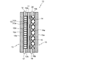
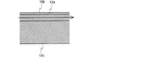
図1は、本発明の一好適な実施の形態に係る有機ハイドライド製造装置(電解セル)の概略構成図である。本発明の電解セル10は、プロトン伝導性を有する固体高分子電解質膜(以下、「電解質膜」とも称す)11と、電解質膜11の一方の面に設けられ、原料である被水素化物を還元して、水素化物を生成するカソード12と、カソード12を収容し、被水素化物が供給されるカソード室13と、電解質膜11の他方の面に設けられ、水を酸化してプロトンを生成する電極触媒含有アノード14(以下、単に「アノード」とも称す)と、アノード14を収容し、電解液が供給されるアノード室15と、を備えている。図示例においては、カソード12は多孔性導電材料であるカソード基材12aとその表面に形成されたカソード触媒層12bとからなる。
Hereinafter, embodiments of the present invention will be described in detail with reference to the drawings.
FIG. 1 is a schematic block diagram of an organic hydride manufacturing apparatus (electrolytic cell) according to a preferred embodiment of the present invention. The
また、図示例においては、カソード室13は、最外部の仕切り板13aと、この仕切り板13aの周縁部と電解質膜11との間に配置されたスペーサ13bからなる。さらに、アノード室15は、最外部の仕切り板15aと、この仕切り板15aの周縁部と電解質膜11との間に配置されたスペーサ15bからなる。さらにまた、仕切り板15aとアノード14との間には、アノード支持用弾性体14aが配置されており、アノード14と電解質膜11との間には、アノードスペーサ16が配置されている。以下、本発明の電解セルの構成について詳細に説明する。
Further, in the illustrated example, the
[カソード室]
本発明の有機ハイドライド製造装置は、カソード室13の下端から被水素化物を供給し、カソード室13の上端から生成物、被水素化物の未反応物および副生水素を排出する構造を有する。図示例においては、カソード室13の下端には、被水素化物入口17が、上端には水素化物出口18が設けられており、アノード室15の下端には酸性電解質入口19が、上端には酸性電解質出口20が設けられている。原料である被水素化物の水素化の反応率を高くすると、電解セル10の出口近傍では被水素化物が低濃度となる。このとき、カソード12への被水素化物の供給が不十分であると、副反応により水素が発生する。水素の発生は、有機化合物の電解系では避けがたい現象であり、特に被水素化物の分解が進み、被水素化物の濃度が低下した場合、定格の電流密度を流そうとすると局部的に水素が発生する。したがって、水素ガスのカソード室13内での蓄積を防止するために、比重の小さい水素ガスをカソード室13上部から排出することが好ましく、これを促進するために、本発明の電解セル10では、液をカソード室13の下部から上部に流すことができる構造としている。
[Cathode chamber]
The organic hydride production apparatus of the present invention has a structure in which the hydride is supplied from the lower end of the
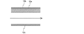
図1に示す例においては、カソード12と仕切り板13aとの間には、カソード支持体12cが介在しており、このカソード支持体12c上に、仕切り12dが設けられている。図2に、本発明の一好適な実施の形態に係る有機ハイドライド製造装置用カソード支持体の概略平面図を、図3に、本発明の一好適な実施の形態に係る有機ハイドライド製造装置のカソード室の概略部分断面図を示す。なお、図3中の矢印は、原料である被水素化物の流れを示す。電解セル10下部から供給される被水素化物を、多孔性導電材料であるカソード基材12aを介して均一に電解セル10内のカソード触媒層12bに供給するために、本発明の有機ハイドライド製造装置においては、図2、3に示すように、適切な間隔で水平の仕切り12dを設けてある。
In the example shown in FIG. 1, the
仕切り12dを設けることで、原料である被水素化物が、多孔性導電材料であるカソード基材12a内に確実に浸透し、高電流密度を与えても反応を進行させることができ、かつ、水素の発生を抑制することができる。また、カソード支持体12cに少なくとも1つの仕切り12dを設けることで、電流集中を防ぐことができ、被水素化物を高電流であっても還元できる。その結果、被水素化物のカソード12における還元反応を高い電流効率で、かつ、小さい電力原単位にて進行させることができる。図示例においては、仕切り12dは、アノード支持用弾性体14aにより押し付けられる力を受け止めて、仕切り12dとカソード12の間の電子伝導性を確保している。
By providing the
低濃度の被水素化物の物質移動を改善するための流路構造として、仕切り12dは、1〜5mmピッチ、0.1〜1mm幅で流路に直交して設けることが好ましい。被水素化物の入口と出口の圧力差も大きくなるが、液の流れがカソード触媒層12b近傍になるため濃度勾配が大きくなり、カソード基材12a内の物質移動が促進されると考えられるためである。仕切り12dとしては、幅0.1mm以上が効果的である。仕切り12dの幅を0.1mm以上とすることで、液体流動時に発生する圧力差を、容易に1kPa/mm以上とすることができる。仕切り12dの幅が0.1mm以下では物質移動への寄与が少なくなり、構造としても複雑になり加工しにくい。なお、液の流路を兼ねるカソード基材12a部分の厚さを0.5〜5mmに調整することで、圧力損失の少ない構造を設計することが可能である。
As a flow path structure for improving the mass transfer of the low concentration object to be hydrided, it is preferable that the
本発明の電解セル10は、被水素化物濃度は、カソード室13の被水素化物入口17より水素化物出口18の方が小さくなる。カソード室13に流入した被水素化物に十分な流速、撹拌がない状態では物質移動が遅くなり、水素化物の濃度が、溶液内部よりもはるかにカソード表面で高くなり、副反応により水素が発生してしまう。電解セル10を大型にする場合、この液流動を確実に均一に維持するために、カソード室13の下部と上部との間に圧力損失があることが好ましい。
In the
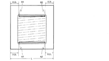
図4は、電解セル内の圧力分布の概略推定図であり、図中の2点鎖線は圧力等高線を示す。図示するように、カソード室13底部から上部に均一に流れる場合には、カソード12の下端の任意の2点、例えば、図示例では、カソード支持体12cの幅をLとしたとき、カソード支持体12cの両側部からそれぞれ0.2Lの位置のA1、A2の被水素化物の圧力差ΔPLの値は、カソード12の上端の任意の2点、例えば、カソード支持体12cの両側部からそれぞれ0.2Lの位置のB1、B2の被水素化物および生成物の混合物の圧力差ΔPHの1/10以下であることが好ましい。この関係が保たれないと、液の流れが不均一化し、局所的な液やガスの滞留が発生し、電解性能の低下を招くことになる。また、被水素化物を定格流量で供給した時、カソード室13内の混合物の圧力差は1kPa/mm以上とすることも好ましい。なお、このような条件を満足させるには、カソード室13内の高さ方向における流路断面積を適宜調整することにより達成することができる。例えば、カソード室13が正方形である場合、上端および下端の流路断面積を上下方向の流路断面積の和の10倍程度とすればよい。
FIG. 4 is a schematic estimation view of pressure distribution in the electrolysis cell, and a two-dot chain line in the drawing indicates a pressure contour. As illustrated, when uniformly flowing from the bottom of the
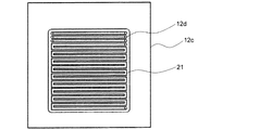
図5に、サーペンタイン流路を有するカソード支持体の概略平面図を、図6に、サーペンタイン流路を有するカソード支持体を備えた有機ハイドライド製造装置のカソード室の概略部分断面図を示す。なお、図6中の矢印は、原料である被水素化物の流れを示す。図5、6に示すサーペンタイン流路を有するカソード支持体12cでは、蛇行する溝21が設けられているだけで、図3、4の仕切り12dにあたる構造が存在しないため、液がカソード基材12a内部に流れ込むことがなく、直線的に流れてしまい、カソード基材12aを介してカソード触媒層12b表面までの物質移動が不十分である。このようなカソード支持体を用いた電解セルにおいては、原料である被水素化物(例えば、トルエン)の濃度が高い場合(モル比20%以上)、例えば電流密度0.4A/cm2のような高電流においても、目的の反応のみが進行する。
FIG. 5 shows a schematic plan view of a cathode support having a serpentine channel, and FIG. 6 shows a schematic partial cross-sectional view of a cathode chamber of an organic hydride manufacturing apparatus provided with a cathode support having a serpentine channel. The arrows in FIG. 6 indicate the flow of the material to be hydrogenated which is the raw material. In the
しかしながら、カソード室13内で被水素化物の濃度が減少する運転状態、例えばカソード室13の出口における被水素化物の濃度が20%以下の場合では、副反応が進行しやすくなる。このような場合、カソード支持体12cに少なくとも1つの仕切り12dを設けてやればよく、好ましくは、仕切り12dを有する部位の面積が電解投影面積の20%以下となるようカソード支持体12cの上部に仕切り12dを複数設ける。これにより、反応効率を向上させることができる。図7は、サーペンタイン流路を有するカソード支持体の上部20%に、仕切りを複数設けたカソード支持体の概略平面図であり、図示する例では、カソード支持体12cの上部に設けられた仕切り12d以外の部分は溝21である。
However, in an operating condition in which the concentration of the hydride is reduced in the
[固体高分子電解質膜]
本発明の電解セル10に用いる電解質膜11としては、酸化反応や有機化合物溶媒に対する長期安定性に優れた、イオン交換基としてスルホン酸を有するフッ素樹脂製材料からなるものが好ましい。電解質膜11は、プロトン伝導性を有する材料(アイオノマー)で形成されており、プロトンを選択的に伝導する一方で、カソード12とアノード14との間で物質が混合したり拡散したりすることを抑制する。電解質膜11の厚さは、5〜300μmが好ましく、10〜200μmがより好ましく、20〜100μmが特に好ましい。電解質膜11の厚さが5μm未満であると、電解質膜11のバリア性が低下し、クロスリークが生じやすくなる。また、電解質膜11の厚さが300μmより厚くなると、イオン移動抵抗が過大になるため好ましくない。
[Solid polymer electrolyte membrane]
As
本発明の電解セル10においては、電解質膜11の表面に凹凸形状を付与することにより親水化してもよく、また、電解質膜11の表面に無機物層を被覆し親水化してもよく、また、これらを併用してもよい。
In the
[カソード]
本発明の電解セル10においては、図示するように、カソード12はカソード基材12aとカソード触媒層12bで構成することができる。本発明の電解セル10のカソード12を構成するカソード基材12aとしては、多孔導電性基材であるカーボンからなるクロス、ペーパー等の繊維焼結体等を用いることができる。多孔性導電基材とする理由は、ガスおよび液の供給や除去のため、適度の多孔性を有しかつ十分な電導性を保つことが好ましいからである。特に、厚さ0.01〜5mm、空隙率が30〜95%、代表的孔径が0.001〜1mmであるものが好ましい。なお、このカソード基材12aの表面に金属成分を共存させると、導電層全体の導電性が向上し、電流の均一化が達成されるため好ましい。
[Cathode]
In the
カーボンクロスは、数μmの径の細いカーボン繊維を数百本の束とし、これを織布としたものであるが、気液透過性に優れているからカソード基材12aとして好ましい。また、カーボンペーパーはカーボン原料繊維を製紙法にて薄膜の前駆体とし、これを焼結したものであるが、これも好適に使用することができる。この炭素製導電性基材に直接給電すると、その不十分な導電性のため、電流の局部集中を起こし、ガス拡散層や反応層にも局部的に集中した電流が供給されて電解効率を低下させるが、金属成分を共存させることにより導電性基材に均一に電流を供給することができる。
The carbon cloth is a bundle of several hundreds of fine carbon fibers with a diameter of several μm and made into a woven fabric, but it is preferable as the
[カソード触媒]
カソード触媒の種類としては、白金、ルテニウム、パラジウム、イリジウム、あるいはそれらの合金から選択される金属の粒子を用いることができる。これらは市販されている粒子を使用してもよいが、公知方法に従って合成し、これを使用してもよい。例えば、合成には、触媒金属イオンを溶解する水溶液に、還元剤を混合して合成する湿式法を採用してもよく、蒸着、スパッターなどの乾式法を採用してもよい。カソード触媒の粒子の粒径は0.001〜1μmが好ましい。
[Cathode catalyst]
As a type of cathode catalyst, particles of a metal selected from platinum, ruthenium, palladium, iridium, or an alloy thereof can be used. Although these may use commercially available particles, they may be synthesized according to known methods and used. For example, for the synthesis, a wet method in which a reducing agent is mixed with an aqueous solution in which catalyst metal ions are dissolved may be employed, or a dry method such as vapor deposition or sputtering may be employed. The particle size of the cathode catalyst particles is preferably 0.001 to 1 μm.
カソード触媒粒子は必ずしもカソード基材12aに担持する必要はないが、担体粒子としてカーボン粒子を使用し、この粒子に展開することにより、触媒表面積を有効に拡大することができる。担体粒子として、通常は炭素微粒子が用いられ、ファーネスブラック、アセチレンブラックなどを使用することができる。炭素微粒子の粒径は0.01〜1μmが好ましい。反応層内の導電性粉末は、親水性触媒粒子の凝集を抑制する機能を有する。
The cathode catalyst particles do not necessarily have to be supported on the
[カソードの製造]
カソード12の製造方法については特に制限はない。例えば、触媒成分粉末、疎水性樹脂、水、ナフサ等の溶剤、アイオノマーであるNafion(登録商標)分散液DE521(DuPont製)を混合し、乾燥後の質量が触媒中のカーボン質量と1:10〜10:1の比率になるよう添加して、適宜溶媒を用いて塗布用の触媒インクを調製する。その後、この触媒インクをカソード基材12aに塗布し、乾燥、焼成によりカソード触媒の粒子をカソード基材12aに固着させればよい。Nafion分散液のアイオノマーは、多孔性構造体内部での導電性のない有機水素化合物における電子移動反応を維持するために有効である。疎水性樹脂(フッ素成分)はガス透過性材料であり、その粉末の粒径としては0.005〜10μmが好ましい。塗布、乾燥、焼成は数回に分けて実施すると、均質なカソード触媒層12bが得られるので好ましい。このようにしてカソード触媒層12bを有するカソード12を作製することができる。
[Manufacture of cathode]
There is no particular limitation on the method of manufacturing the
本発明の電解セル10においては、触媒インク成分を用いてカソード触媒層を電解質膜11上に形成してもよい。電解質膜11の片面にバーコーター塗布法によりカソード触媒層を形成し、カソード−電解質膜複合体とすることもできる。この触媒インクを、電解質膜11上に、触媒中のPtとRuを合わせた質量が電極面積あたり0.5mg/cm2となるようにスプレー塗布し、インク中の溶媒成分を乾燥して、電解質膜−触媒の接合体を得ることもできる。
In the
カソード基材12aは厚さ方向に圧力を加えて使用するため、これによって厚さ方向の導電性が変化することは好ましくない。性能向上および20〜50%の充填率を有する陰極にする目的で、プレス加工を施すことが好ましい。プレス加工は、炭素材料を圧縮することによってその導電性を高めるとともに、圧力を加えて使用した際の充填率および導電性変化を安定化させるために行う。カソード触媒層12bとカソード基材12aの接合度が向上することも導電性向上に寄与する。また、カソード基材12aと反応層の圧縮、およびカソード触媒層12bとカソード基材12aとの接合度の向上によって、原料物質の供給および生成物質の除去能力が増大する。プレス加工装置としては、ホットプレス、ホットローラー等の公知の装置を利用できる。プレス条件としては、室温〜360℃にて、圧力0.1〜5MPaが望ましい。以上により、高い導電性と反応性を有するカソード12を製造することができる。
Since the
[アノード]
本発明の電解セル10のアノード14を構成するアノード基材としては、電解に必要な電流を流すための十分な電気伝導性を有し、電解セル10を構成する機械的強度の必要性から、厚さとしては0.1mmから2mmの板状材料が好ましい。ガス発生電極では気泡による抵抗の増大を避け、被電解液の供給を促進するため、多孔体で酸性電解質に対する耐食性に優れていることが好ましく、チタン製エキスパンドメッシュが汎用されている。メッシュ加工後は3次元的構造となるため、適切に平滑化処理を行う。最適なエキスパンドメッシュの厚さの範囲は0.1〜2mm、短目方向中心間距離は0.1〜4mm、長目方向中心間距離は0.1〜4mm、開口率は30〜70%程度が望ましい。
[anode]
The anode substrate constituting the
[アノードの製造]
アノード14の製造は、好ましくは、アノード基材となるチタンの表面に乾式ブラスト処理、ついで20%硫酸など水溶液中での洗浄処理を行う。その後、洗浄したアノード14表面に、アークイオンプレーティング装置によって、チタン−タンタル層などを形成する。これはチタン基材が電解中に進行する腐食を抑制するためである。チタン−タンタル層の厚さとしては、0.1〜10μmが好ましい。その後、イリジウム(Ir)およびタンタル成分を溶解させた混合水溶液を塗布し、ついで電気炉にて360〜550℃の熱処理を施す操作を複数回繰返すことにより、アノードを製造することができる。本発明の電解セルに係るアノードにおいては、酸化イリジウムと酸化タンタルとからなる電極触媒層を、電極面積当たりのIr金属量換算で1〜40g/m2となるよう形成したものをアノード14として好適に用いることができる。
[Manufacture of anode]
In the manufacture of the
[セル構造]
図1に示す本発明の電解セル10のカソード室13の外部には、電子伝導性を有する仕切り板13aが配設されている。仕切り板13aは、例えば、ステンレス等の金属で形成される。仕切り板13aの周縁部と、電解質膜11との間にスペーサ13bが取り付けられており、仕切り板13a、スペーサ13bおよび電解質膜11で囲まれる空間がカソード室13となっている。スペーサ13bは、被水素化物および水素化物を含む有機物がカソード室13の外へ漏洩することを防ぐシール材を兼ねており、電子的に絶縁性であることが望ましい。スペーサ13bの材料としては、たとえば、4フッ化エチレン樹脂が挙げられる。
Cell structure
Outside the
図示例においては、スペーサ13bの下部に被水素化物入口17が設けられており、この被水素化物入口17からカソード室13にトルエン等の被水素化物が供給される。また、スペーサ13bの上部には水素化物出口18が設けられており、この水素化物出口18を介してトルエンの水素化物であるメチルシクロヘキサン等水素化物を含む有機物が系外に排出される。
In the illustrated example, a
本発明の電解セル10のアノード室15の外部には、電子伝導性を有する仕切り板15aが配設されている。仕切り板15aは、たとえば、チタンなどの金属で形成される。仕切り板15aのアノード14側面の周縁部と、電解質膜11との間にスペーサ15bが取り付けられており、仕切り板15a、アノード室15側端部のスペーサ15bおよび電解質膜11で囲まれる空間がアノード室15となっている。スペーサ15bは、酸性電解液がアノード室15の外へ漏洩することを防ぐシール材を兼ねており、電子的に絶縁性であることが望ましい。スペーサ15bの材料としては、例えば、4フッ化エチレン樹脂等が挙げられる。
Outside the
図示例においては、スペーサ15bの下部に酸性電解液入口19が設けられており、この酸性電解液入口19からアノード室15に酸性電解液が供給される。酸性電解液としては、20℃で測定したイオン伝導度が0.01S/cm以上の硫酸、リン酸、硝酸または塩酸が挙げられる。酸性電解液のイオン伝導度が0.01S/cmより低いと、工業的に十分な電気化学反応を得にくくなる。また、スペーサ15bの上部には酸性電解液出口20が設けられており、この酸性電解液出口20を介してアノード室15に貯蔵されている酸性電解液が系外に排出される。
In the illustrated example, an
また、図示例においては、アノード14と仕切り板15aとの間にはアノード支持用弾性体14aが配置されており、アノード支持用弾性体14aによってアノード14が電解質膜11に押し付けられる。アノード支持用弾性体14aは、例えば、板バネやコイル構造の電子伝導体で形成される。図示例においては、アノード14と電解質膜11との間にアノードスペーサ16が介在しており、アノードスペーサ16によりアノード14と電解質膜11との間に所定のギャップが保たれるように構成されている。このように、アノード室15を構成する仕切り板15aとアノード14との間にアノード支持用弾性体14aを設けてアノード14を保持する構造とすることにより、アノード14の交換等のメンテナンス作業を容易にすることができる。
Further, in the illustrated example, an
アノード支持用弾性体14aは、酸性電解液入口19から流入する酸性電解液に対して耐酸性を有する材料で形成されることが好ましく、基材としてチタンまたはチタン合金が好ましく使用される。アノード支持用弾性体14aを構成する弾性体構造としてはV字型スプリング、Xクロススプリング、クッションコイルのタイプやビビリ繊維の集合体など各種構造が考えられる。それぞれの必要面圧は各部材の接触抵抗を鑑みて、材料厚み等が適宜選択される。
The anode supporting
以下、本発明の実施例を詳細に説明するが、これら実施例は、本発明を好適に説明するための例示に過ぎず、なんら本発明を限定するものではない。 EXAMPLES Hereinafter, examples of the present invention will be described in detail, but these examples are merely examples for suitably explaining the present invention, and the present invention is not limited at all.
<実施例1>
パーフルオロカーボンスルホン酸系膜の両面に貴金属担持カーボン触媒層を接合した電極/膜接合体のカソード側にトルエンを、アノード側に加湿水素を供給してトルエンの水素化反応を電気化学的に評価した。アノードの水素酸化反応の分極は非常に小さいので、アノードを擬似的な可逆水素電極(RHE)兼対極とし、アノードにはPt/C触媒(田中貴金属工業,TEC10E50E)0.5mgcm−2、カソードにはPtRu/C触媒(田中貴金属工業,TEC61E54E)0.5mgcm−2をNafion溶液(デュポン,DE521)とともに塗工したカーボンペーパー(SGLカーボン,35BC)を用いた。電極面積は25cm2とした。電解質膜はNafion NRE212CSとしアノードおよびカソードを接合して膜−電極接合体とした。
Example 1
The hydrogenation reaction of toluene was electrochemically evaluated by supplying toluene to the cathode side of an electrode / membrane assembly in which a noble metal-supported carbon catalyst layer was bonded to both sides of a perfluorocarbon sulfonic acid-based membrane and humidified hydrogen to the anode side. . Since the polarization of the hydrogen oxidation reaction of the anode is very small, the anode is used as a pseudo-reversible hydrogen electrode (RHE) and counter electrode, and the anode is Pt / C catalyst (Tanaka precious metal industry, TEC10E50E) 0.5 mg cm -2 , cathode The carbon paper (SGL carbon, 35BC) which used PtRu / C catalyst (Tanaka precious metal industry, TEC61E54E) 0.5 mgcm <-2 > with Nafion solution (Dupont, DE521) was used. The electrode area was 25 cm 2 . The electrolyte membrane was Nafion NRE 212 CS, and the anode and the cathode were joined to form a membrane-electrode assembly.
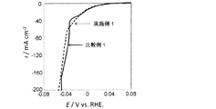
アノードには100%RH加湿水素を100mLmin−1供給、カソードにはTL/MCH(TL濃度5%)を5mLmin−1ポンプで循環した。セル温度は60℃とし、1mVs−1でLinear Scan Voltammetry(LSV)による分極を評価した。カソードの流路構造については、流れ方向に対して1mmピッチ、1mm幅の平行の仕切りを全面に21本設けた図2、3に示すタイプのカソード支持体を用いた。実施例1の電解セルでは60mAcm−2まで水素ガス発生が起こらなかった。カソード出入口の圧力差はΔPLが0.004MPaで、ΔPHが0.044MPaであった。なお、電解セルの構造は図1に示すタイプの構造とした。 The anode was supplied with 100 mL min- 1 humidified hydrogen at 100% RH, and the cathode was circulated with a 5 mL min- 1 pump using TL / MCH (TL concentration: 5%). The cell temperature was 60 ° C., and the polarization by Linear Scan Voltammetry (LSV) was evaluated at 1 mVs −1 . As for the flow channel structure of the cathode, a cathode support of the type shown in FIGS. 2 and 3 was provided with 21 parallel partitions of 1 mm pitch and 1 mm width in the flow direction. In the electrolytic cell of Example 1, hydrogen gas generation did not occur up to 60 mA cm- 2 . The pressure difference between the cathode and the inlet was 0.004 MPa for ΔP L and 0.044 MPa for ΔP H. In addition, the structure of the electrolysis cell was taken as the structure of the type shown in FIG.
<比較例1>
図5に示すタイプの平面構造を有する、1mmピッチのサーペンタイン流路を有するカソード支持体を用いたこと以外は実施例1と同様な試験を実施した。サーペンタイン流路では40mAcm−2で水素ガスの発生が始まった。カソード側の出入口間の圧力差はほぼ0MPaであった。図8に、実施例1の電解セルと比較例1の電解セルにトルエン5%を導入した時の−0.08V〜0.08V vs.RHEでの分極曲線を示す。
Comparative Example 1
The same tests as in Example 1 were carried out except that a cathode support having a 1 mm pitch serpentine channel having a planar structure of the type shown in FIG. 5 was used. In the serpentine flow path, generation of hydrogen gas started at 40 mA cm- 2 . The pressure difference between the inlet and the outlet on the cathode side was approximately 0 MPa. In FIG. 8, when 5% of toluene is introduced into the electrolytic cell of Example 1 and the electrolytic cell of Comparative Example 1, -0.08 V to 0.08 V vs. The polarization curve in RHE is shown.
<実施例2>
図9に示すタイプの平面構造を有するカソード支持体を用いた。カソード支持体12c
の構造は、上端と下端に1.5mmの溝21を一つと溝21に1.5mmの仕切り12d
を一つとした。これ以外は実施例1と同様な試験を実施した。流路では60mAcm−2まで水素ガス発生が起こらなかった。カソード出入口の圧力差はΔPLが0.004MPaで、ΔPHが0.104MPaであった。図10に、実施例2で用いた有機ハイドライド製造装置のカソード室の概略部分断面図を示す。
Example 2
A cathode support having a planar structure of the type shown in FIG. 9 was used.
In the above structure, one 1.5
Was one. The same test as in Example 1 was conducted except for this . It did not occur hydrogen gas generation until 60MAcm -2 in the flow path. The pressure difference between the cathode and the inlet was 0.004 MPa for ΔP L and 0.104 MPa for ΔP H. FIG. 10 shows a schematic partial cross-sectional view of the cathode chamber of the organic hydride manufacturing apparatus used in Example 2.
<比較例2>
トルエンの供給をカソード室の上部から行ったこと以外は実施例1と同様に電解した。サーペンタイン流路では50mAcm−2で水素ガス発生が始まった。なお、100mAcm−2の電流を流したところ5分後に槽電圧が上がり電流が流れなくなった。
Comparative Example 2
Electrolysis was performed in the same manner as in Example 1 except that the supply of toluene was performed from the top of the cathode chamber. Hydrogen gas generation started at 50 mA cm -2 in the serpentine flow channel. When a current of 100 mA cm −2 was applied, the cell voltage rose after 5 minutes and the current stopped flowing.
<比較例3>
図11に示すタイプの平面構造を有する、平坦なカソード支持体12cの上端に出口穴12fと下端に入口穴12eを設け、カーボンペーパー内を流路としたカソード支持体を用いたこと以外は実施例1と同様な試験を実施した。流路では30mAcm−2で水素ガス発生が起こった。
Comparative Example 3
It is carried out except that an
<実施例3>
図7に示すタイプ平面構造を有する、カソード支持体の電解投影面積14%に当たる上部の部分に、流れ方向に対して垂直に1mmピッチ、1mm幅の平行の仕切り12dを設けたカソード支持体12cを用いた。カソード室下部の入口からトルエンを供給し、カソード上部の出口におけるトルエン濃度が5%となるように制御して電解を行ったところ、60mAcm−2まで水素ガス発生が起こらなかった。なお、電解セルの構造は図1に示すタイプの構造とした。
Example 3
A
<比較例4>
カソード支持体として仕切り12dを設けなかったものを用いたこと以外は、実施例4と同様の電解を行ったところ、40mAcm−2で水素ガス発生が起こった。
Comparative Example 4
When electrolysis similar to Example 4 was performed except having used what did not provide
本発明は、上述の実施の形態に限定されるものではなく、当業者の知識に基づいて各種の設計変更等の変形を加えることも可能であり、そのような変形が加えられた実施の形態も本発明の範囲に含まれうるものである。 The present invention is not limited to the embodiments described above, and various modifications such as design changes can be added based on the knowledge of those skilled in the art, and such embodiments can be added. Are also included in the scope of the present invention.
10 有機ハイドライド製造用電解セル(電解セル)
11 固体高分子電解質膜(電解質膜)
12 カソード
12a カソード基材
12b カソード触媒層
12c カソード支持体
12d 仕切り
12e 入口穴
12f 出口穴
13 カソード室
13a 仕切り板
13b スペーサ
14 電極触媒含有アノード(アノード)
14a アノード支持用弾性体
15 アノード室
15a 仕切り板
15b スペーサ
16 アノードスペーサ
17 被水素化物入口
18 水素化物出口
19 酸性電解液入口
20 酸性電解液出口
21 溝
10 Electrolysis cell for production of organic hydride (electrolysis cell)
11 Solid polymer electrolyte membrane (electrolyte membrane)
12
14a Anode supporting
Claims (5)
前記カソード室の下端から前記被水素化物が供給され、前記カソード室の上端から生成物、前記被水素化物の未反応物および副生水素が排出される構造を有し、前記カソード室内に、幅0.1mm以上の仕切りが少なくとも一つ形成されていることを特徴とする有機ハイドライド製造装置。 A solid polymer electrolyte membrane having proton conductivity, a porous cathode provided on one surface of the solid polymer electrolyte membrane for reducing a hydride to form a hydride, and containing the porous cathode A cathode chamber to which a hydride is supplied, and an electrode catalyst-containing anode which is provided on the other surface of the solid polymer electrolyte membrane and which oxidizes water to generate a proton, and the anode; And an anode chamber to be supplied.
The object to be hydrogenated is supplied from the lower end of the cathode chamber, and the product, the unreacted product of the object to be hydrogenated and by-product hydrogen are discharged from the upper end of the cathode chamber. An organic hydride manufacturing apparatus characterized in that at least one partition of 0.1 mm or more is formed.
前記カソード室の下端から前記被水素化物を供給し、前記カソード室の上端から生成物、前記被水素化物の未反応物および副生水素を排出することを特徴とする有機ハイドライドの製造方法。 In the method for producing an organic hydride using the organic hydride producing apparatus according to claim 1 or 2 ,
A method for producing an organic hydride, comprising supplying the object to be hydrogenated from the lower end of the cathode chamber and discharging a product, an unreacted product of the object to be hydrogenated and by-product hydrogen from the upper end of the cathode chamber.
ΔPL≦ΔPH/10
で表される関係を満足する請求項3記載の有機ハイドライドの製造方法。 When the hydride is supplied to the organic hydride production apparatus at a rated flow rate, the pressure difference between the two hydrides at the lower end of the cathode is ΔP L , and the pressure difference between the mixture at the two upper ends of the cathode is ΔP When H , the following formula,
ΔP L ≦ ΔP H / 10
The manufacturing method of the organic hydride of Claim 3 which satisfies the relationship represented by these.
Priority Applications (9)
| Application Number | Priority Date | Filing Date | Title |
|---|---|---|---|
| JP2014236772A JP6501141B2 (en) | 2014-11-21 | 2014-11-21 | Organic hydride manufacturing apparatus and method of manufacturing organic hydride using the same |
| CN201580063189.1A CN107075700B (en) | 2014-11-21 | 2015-11-19 | The manufacturing method of organic hydride material producing device and the organic hydride using it |
| DK15862087.2T DK3222754T3 (en) | 2014-11-21 | 2015-11-19 | APPARATUS FOR THE PRODUCTION OF ORGANIC HYDRID AND THE PROCEDURE FOR THE PRODUCTION OF ORGANIC HYDRID WHEN USING IT |
| CA2968036A CA2968036C (en) | 2014-11-21 | 2015-11-19 | Apparatus for producing organic hydride and method for producing organic hydride using same |
| US15/528,438 US11035045B2 (en) | 2014-11-21 | 2015-11-19 | Apparatus for producing organic hydride and method for producing organic hydride using same |
| PCT/JP2015/082616 WO2016080505A1 (en) | 2014-11-21 | 2015-11-19 | Apparatus for producing organic hydride and method for producing organic hydride using same |
| KR1020177017132A KR102471656B1 (en) | 2014-11-21 | 2015-11-19 | Apparatus for producing organic hydride and method for producing organic hydride using same |
| EP15862087.2A EP3222754B1 (en) | 2014-11-21 | 2015-11-19 | Apparatus for producing organic hydride and method for producing organic hydride using same |
| ES15862087T ES2846853T3 (en) | 2014-11-21 | 2015-11-19 | Apparatus for producing organic hydride and procedure for producing organic hydride using the same |
Applications Claiming Priority (1)
| Application Number | Priority Date | Filing Date | Title |
|---|---|---|---|
| JP2014236772A JP6501141B2 (en) | 2014-11-21 | 2014-11-21 | Organic hydride manufacturing apparatus and method of manufacturing organic hydride using the same |
Publications (3)
| Publication Number | Publication Date |
|---|---|
| JP2016098410A JP2016098410A (en) | 2016-05-30 |
| JP2016098410A5 JP2016098410A5 (en) | 2017-07-06 |
| JP6501141B2 true JP6501141B2 (en) | 2019-04-17 |
Family
ID=56014037
Family Applications (1)
| Application Number | Title | Priority Date | Filing Date |
|---|---|---|---|
| JP2014236772A Active JP6501141B2 (en) | 2014-11-21 | 2014-11-21 | Organic hydride manufacturing apparatus and method of manufacturing organic hydride using the same |
Country Status (9)
| Country | Link |
|---|---|
| US (1) | US11035045B2 (en) |
| EP (1) | EP3222754B1 (en) |
| JP (1) | JP6501141B2 (en) |
| KR (1) | KR102471656B1 (en) |
| CN (1) | CN107075700B (en) |
| CA (1) | CA2968036C (en) |
| DK (1) | DK3222754T3 (en) |
| ES (1) | ES2846853T3 (en) |
| WO (1) | WO2016080505A1 (en) |
Families Citing this family (16)
| Publication number | Priority date | Publication date | Assignee | Title |
|---|---|---|---|---|
| KR102028915B1 (en) | 2014-03-28 | 2019-10-07 | 내셔널 유니버서티 코포레이션 요코하마 내셔널 유니버서티 | Device for producing organic hydride |
| JP6758628B2 (en) * | 2016-11-15 | 2020-09-23 | 国立大学法人横浜国立大学 | Organic hydride manufacturing equipment and organic hydride manufacturing method |
| JP6954561B2 (en) * | 2017-05-23 | 2021-10-27 | 国立大学法人横浜国立大学 | Organic hydride manufacturing equipment |
| JP2019056136A (en) | 2017-09-20 | 2019-04-11 | 株式会社東芝 | Electrochemical reaction device |
| KR20190083546A (en) | 2018-01-04 | 2019-07-12 | (주)엘켐텍 | Electrochemical hydrogenation reactor and method of hydrogenation using the same |
| DE102018201287A1 (en) * | 2018-01-29 | 2019-08-01 | Siemens Aktiengesellschaft | Porous electrode for the electrochemical conversion of organic compounds into two immiscible phases in an electrochemical flux reactor |
| JP2019143212A (en) * | 2018-02-22 | 2019-08-29 | パナソニックIpマネジメント株式会社 | Electrolysis device |
| JP7372797B2 (en) * | 2019-09-20 | 2023-11-01 | Eneos株式会社 | Organic hydride generation system and method for controlling the organic hydride generation system |
| JP7426817B2 (en) * | 2019-12-26 | 2024-02-02 | Eneos株式会社 | Organic hydride generation system, control device for organic hydride generation system, and control method for organic hydride generation system |
| WO2022091361A1 (en) * | 2020-10-30 | 2022-05-05 | Eneos株式会社 | Organic hydride production apparatus, and method for forming cathode catalyst layer |
| WO2022091360A1 (en) * | 2020-10-30 | 2022-05-05 | Eneos株式会社 | Device for manufacturing organic hydride |
| CN112941552B (en) * | 2021-01-27 | 2024-04-09 | 云南电网有限责任公司电力科学研究院 | Porous carbon supported ruthenium catalyst and preparation method thereof |
| EP4296405A1 (en) * | 2021-02-19 | 2023-12-27 | ENEOS Corporation | Apparatus for producing organic hydride and method for producing organic hydride |
| JP2022143970A (en) * | 2021-03-18 | 2022-10-03 | 株式会社東芝 | Carbon dioxide electrolytic apparatus |
| WO2023176198A1 (en) * | 2022-03-17 | 2023-09-21 | Eneos株式会社 | Organic hydride production device |
| WO2023176197A1 (en) * | 2022-03-17 | 2023-09-21 | Eneos株式会社 | Organic hydride manufacturing device |
Family Cites Families (22)
| Publication number | Priority date | Publication date | Assignee | Title |
|---|---|---|---|---|
| JPS497210B1 (en) | 1970-12-23 | 1974-02-19 | ||
| US4247376A (en) * | 1979-01-02 | 1981-01-27 | General Electric Company | Current collecting/flow distributing, separator plate for chloride electrolysis cells utilizing ion transporting barrier membranes |
| JP2700052B2 (en) * | 1995-03-08 | 1998-01-19 | 工業技術院長 | Hydride production method |
| JP3915334B2 (en) | 1999-08-30 | 2007-05-16 | 株式会社豊田自動織機 | Hydrogen supply system for fuel cell, fuel recycling method, mobile body for transporting liquid, fueling facility, and fuel recycling system |
| CN1403630A (en) * | 2002-09-26 | 2003-03-19 | 上海交通大学 | Aniline-synthesizing and electric energy-generating process utilizing proton exchange film fuel cell |
| US20080234527A1 (en) | 2004-03-09 | 2008-09-25 | Takaya Matsumoto | Method for Producing Hydrogen and System Therefor |
| JP5046359B2 (en) | 2006-03-06 | 2012-10-10 | 株式会社フレイン・エナジー | Hydrogen generator and hydrogenation reactor |
| JP4907210B2 (en) | 2006-03-30 | 2012-03-28 | 千代田化工建設株式会社 | Hydrogen storage and transport system |
| JP2009007647A (en) | 2007-06-29 | 2009-01-15 | Hitachi Ltd | Organic hydride manufacturing apparatus and distributed power supply and automobile using the same |
| EP2300641A4 (en) * | 2008-06-16 | 2015-08-26 | Richards William R | Alkaline electrolyzer |
| JP5737853B2 (en) | 2010-03-29 | 2015-06-17 | 千代田化工建設株式会社 | Method for producing hydrogen for storage and transportation |
| WO2012028166A1 (en) | 2010-09-03 | 2012-03-08 | Ev Group E. Thallner Gmbh | Device and method for reducing a wedge error |
| JP2012072477A (en) * | 2010-09-30 | 2012-04-12 | Hitachi Ltd | Device for manufacturing organic hydride |
| WO2012091128A1 (en) | 2010-12-28 | 2012-07-05 | Jx日鉱日石エネルギー株式会社 | Organic compound hydrogenation device and hydrogenation method |
| JP2013084360A (en) * | 2011-10-06 | 2013-05-09 | Hitachi Ltd | Membrane-electrode assembly, and device for organic hydride production |
| CA2861209A1 (en) * | 2012-01-24 | 2013-08-01 | Jx Nippon Oil & Energy Corporation | Electrochemical reduction device and method for manufacturing hydride of aromatic hydrocarbon compound or n-containing heterocyclic aromatic compound |
| US11566332B2 (en) | 2012-03-06 | 2023-01-31 | Board Of Trustees Of Michigan State University | Electrocatalytic hydrogenation and hydrodeoxygenation of oxygenated and unsaturated organic compounds |
| JP5945154B2 (en) * | 2012-04-27 | 2016-07-05 | ティッセンクルップ・ウーデ・クロリンエンジニアズ株式会社 | Ion exchange membrane electrolytic cell |
| KR101395219B1 (en) | 2012-05-30 | 2014-05-15 | (주)펨트론 | Display glass holding module |
| US9951431B2 (en) | 2012-10-24 | 2018-04-24 | Board Of Trustees Of Michigan State University | Electrocatalytic hydrogenation and hydrodeoxygenation of oxygenated and unsaturated organic compounds |
| KR102028915B1 (en) * | 2014-03-28 | 2019-10-07 | 내셔널 유니버서티 코포레이션 요코하마 내셔널 유니버서티 | Device for producing organic hydride |
| JP6400410B2 (en) * | 2014-09-25 | 2018-10-03 | 国立大学法人横浜国立大学 | Electrolysis cell for organic chemical hydride production |
-
2014
- 2014-11-21 JP JP2014236772A patent/JP6501141B2/en active Active
-
2015
- 2015-11-19 WO PCT/JP2015/082616 patent/WO2016080505A1/en active Application Filing
- 2015-11-19 CN CN201580063189.1A patent/CN107075700B/en active Active
- 2015-11-19 CA CA2968036A patent/CA2968036C/en active Active
- 2015-11-19 DK DK15862087.2T patent/DK3222754T3/en active
- 2015-11-19 ES ES15862087T patent/ES2846853T3/en active Active
- 2015-11-19 US US15/528,438 patent/US11035045B2/en active Active
- 2015-11-19 KR KR1020177017132A patent/KR102471656B1/en active IP Right Grant
- 2015-11-19 EP EP15862087.2A patent/EP3222754B1/en active Active
Also Published As
| Publication number | Publication date |
|---|---|
| DK3222754T3 (en) | 2021-01-25 |
| US20170314145A1 (en) | 2017-11-02 |
| EP3222754A1 (en) | 2017-09-27 |
| JP2016098410A (en) | 2016-05-30 |
| EP3222754B1 (en) | 2020-12-30 |
| CN107075700B (en) | 2019-04-19 |
| WO2016080505A1 (en) | 2016-05-26 |
| ES2846853T3 (en) | 2021-07-29 |
| EP3222754A4 (en) | 2018-08-22 |
| KR102471656B1 (en) | 2022-11-25 |
| CN107075700A (en) | 2017-08-18 |
| CA2968036C (en) | 2022-08-16 |
| CA2968036A1 (en) | 2016-05-26 |
| KR20170085591A (en) | 2017-07-24 |
| US11035045B2 (en) | 2021-06-15 |
Similar Documents
| Publication | Publication Date | Title |
|---|---|---|
| JP6501141B2 (en) | Organic hydride manufacturing apparatus and method of manufacturing organic hydride using the same | |
| JP6539285B2 (en) | Anode for oxygen generation | |
| JP6400410B2 (en) | Electrolysis cell for organic chemical hydride production | |
| US20060099482A1 (en) | Fuel cell electrode | |
| EP3543377B1 (en) | Apparatus for producing organic hydride and method for producing organic hydride | |
| US20220333257A1 (en) | Organic hydride production device | |
| WO2018037774A1 (en) | Cathode, electrolysis cell for producing organic hydride, and organic hydride production method | |
| JP6998797B2 (en) | Organic hydride manufacturing equipment, organic hydride manufacturing method and energy transportation method | |
| WO2024034444A1 (en) | Apparatus for producing organic hydride | |
| WO2022091361A1 (en) | Organic hydride production apparatus, and method for forming cathode catalyst layer |
Legal Events
| Date | Code | Title | Description |
|---|---|---|---|
| A521 | Request for written amendment filed |
Free format text: JAPANESE INTERMEDIATE CODE: A523 Effective date: 20170519 |
|
| A621 | Written request for application examination |
Free format text: JAPANESE INTERMEDIATE CODE: A621 Effective date: 20170519 |
|
| A131 | Notification of reasons for refusal |
Free format text: JAPANESE INTERMEDIATE CODE: A131 Effective date: 20180807 |
|
| A521 | Request for written amendment filed |
Free format text: JAPANESE INTERMEDIATE CODE: A523 Effective date: 20181009 |
|
| TRDD | Decision of grant or rejection written | ||
| A01 | Written decision to grant a patent or to grant a registration (utility model) |
Free format text: JAPANESE INTERMEDIATE CODE: A01 Effective date: 20190212 |
|
| A61 | First payment of annual fees (during grant procedure) |
Free format text: JAPANESE INTERMEDIATE CODE: A61 Effective date: 20190307 |
|
| R150 | Certificate of patent or registration of utility model |
Ref document number: 6501141 Country of ref document: JP Free format text: JAPANESE INTERMEDIATE CODE: R150 |
|
| R250 | Receipt of annual fees |
Free format text: JAPANESE INTERMEDIATE CODE: R250 |
|
| R250 | Receipt of annual fees |
Free format text: JAPANESE INTERMEDIATE CODE: R250 |
|
| R250 | Receipt of annual fees |
Free format text: JAPANESE INTERMEDIATE CODE: R250 |