EP2659165B1 - Leistungsverzweigungsgetriebe - Google Patents
Leistungsverzweigungsgetriebe Download PDFInfo
- Publication number
- EP2659165B1 EP2659165B1 EP11833600.7A EP11833600A EP2659165B1 EP 2659165 B1 EP2659165 B1 EP 2659165B1 EP 11833600 A EP11833600 A EP 11833600A EP 2659165 B1 EP2659165 B1 EP 2659165B1
- Authority
- EP
- European Patent Office
- Prior art keywords
- power
- split transmission
- transmission according
- gear
- hydraulic motor
- Prior art date
- Legal status (The legal status is an assumption and is not a legal conclusion. Google has not performed a legal analysis and makes no representation as to the accuracy of the status listed.)
- Not-in-force
Links
Images
Classifications
-
- F—MECHANICAL ENGINEERING; LIGHTING; HEATING; WEAPONS; BLASTING
- F16—ENGINEERING ELEMENTS AND UNITS; GENERAL MEASURES FOR PRODUCING AND MAINTAINING EFFECTIVE FUNCTIONING OF MACHINES OR INSTALLATIONS; THERMAL INSULATION IN GENERAL
- F16H—GEARING
- F16H39/00—Rotary fluid gearing using pumps and motors of the volumetric type, i.e. passing a predetermined volume of fluid per revolution
- F16H39/04—Rotary fluid gearing using pumps and motors of the volumetric type, i.e. passing a predetermined volume of fluid per revolution with liquid motor and pump combined in one unit
-
- F—MECHANICAL ENGINEERING; LIGHTING; HEATING; WEAPONS; BLASTING
- F16—ENGINEERING ELEMENTS AND UNITS; GENERAL MEASURES FOR PRODUCING AND MAINTAINING EFFECTIVE FUNCTIONING OF MACHINES OR INSTALLATIONS; THERMAL INSULATION IN GENERAL
- F16H—GEARING
- F16H47/00—Combinations of mechanical gearing with fluid clutches or fluid gearing
- F16H47/02—Combinations of mechanical gearing with fluid clutches or fluid gearing the fluid gearing being of the volumetric type
- F16H47/04—Combinations of mechanical gearing with fluid clutches or fluid gearing the fluid gearing being of the volumetric type the mechanical gearing being of the type with members having orbital motion
-
- F—MECHANICAL ENGINEERING; LIGHTING; HEATING; WEAPONS; BLASTING
- F16—ENGINEERING ELEMENTS AND UNITS; GENERAL MEASURES FOR PRODUCING AND MAINTAINING EFFECTIVE FUNCTIONING OF MACHINES OR INSTALLATIONS; THERMAL INSULATION IN GENERAL
- F16H—GEARING
- F16H3/00—Toothed gearings for conveying rotary motion with variable gear ratio or for reversing rotary motion
- F16H3/44—Toothed gearings for conveying rotary motion with variable gear ratio or for reversing rotary motion using gears having orbital motion
-
- F—MECHANICAL ENGINEERING; LIGHTING; HEATING; WEAPONS; BLASTING
- F16—ENGINEERING ELEMENTS AND UNITS; GENERAL MEASURES FOR PRODUCING AND MAINTAINING EFFECTIVE FUNCTIONING OF MACHINES OR INSTALLATIONS; THERMAL INSULATION IN GENERAL
- F16H—GEARING
- F16H37/00—Combinations of mechanical gearings, not provided for in groups F16H1/00 - F16H35/00
- F16H37/02—Combinations of mechanical gearings, not provided for in groups F16H1/00 - F16H35/00 comprising essentially only toothed or friction gearings
- F16H37/06—Combinations of mechanical gearings, not provided for in groups F16H1/00 - F16H35/00 comprising essentially only toothed or friction gearings with a plurality of driving or driven shafts; with arrangements for dividing torque between two or more intermediate shafts
- F16H37/08—Combinations of mechanical gearings, not provided for in groups F16H1/00 - F16H35/00 comprising essentially only toothed or friction gearings with a plurality of driving or driven shafts; with arrangements for dividing torque between two or more intermediate shafts with differential gearing
- F16H37/0833—Combinations of mechanical gearings, not provided for in groups F16H1/00 - F16H35/00 comprising essentially only toothed or friction gearings with a plurality of driving or driven shafts; with arrangements for dividing torque between two or more intermediate shafts with differential gearing with arrangements for dividing torque between two or more intermediate shafts, i.e. with two or more internal power paths
- F16H37/084—Combinations of mechanical gearings, not provided for in groups F16H1/00 - F16H35/00 comprising essentially only toothed or friction gearings with a plurality of driving or driven shafts; with arrangements for dividing torque between two or more intermediate shafts with differential gearing with arrangements for dividing torque between two or more intermediate shafts, i.e. with two or more internal power paths at least one power path being a continuously variable transmission, i.e. CVT
- F16H2037/088—Power split variators with summing differentials, with the input of the CVT connected or connectable to the input shaft
- F16H2037/0886—Power split variators with summing differentials, with the input of the CVT connected or connectable to the input shaft with switching means, e.g. to change ranges
-
- F—MECHANICAL ENGINEERING; LIGHTING; HEATING; WEAPONS; BLASTING
- F16—ENGINEERING ELEMENTS AND UNITS; GENERAL MEASURES FOR PRODUCING AND MAINTAINING EFFECTIVE FUNCTIONING OF MACHINES OR INSTALLATIONS; THERMAL INSULATION IN GENERAL
- F16H—GEARING
- F16H37/00—Combinations of mechanical gearings, not provided for in groups F16H1/00 - F16H35/00
- F16H37/02—Combinations of mechanical gearings, not provided for in groups F16H1/00 - F16H35/00 comprising essentially only toothed or friction gearings
- F16H37/04—Combinations of toothed gearings only
- F16H37/042—Combinations of toothed gearings only change gear transmissions in group arrangement
-
- F—MECHANICAL ENGINEERING; LIGHTING; HEATING; WEAPONS; BLASTING
- F16—ENGINEERING ELEMENTS AND UNITS; GENERAL MEASURES FOR PRODUCING AND MAINTAINING EFFECTIVE FUNCTIONING OF MACHINES OR INSTALLATIONS; THERMAL INSULATION IN GENERAL
- F16H—GEARING
- F16H39/00—Rotary fluid gearing using pumps and motors of the volumetric type, i.e. passing a predetermined volume of fluid per revolution
- F16H39/02—Rotary fluid gearing using pumps and motors of the volumetric type, i.e. passing a predetermined volume of fluid per revolution with liquid motors at a distance from liquid pumps
Definitions
- the invention relates to a hydrostatic mechanical power split transmission according to generic part of the first claim.
- a hydrostatic mechanical power split transmission is used for example in the DE 10 2004 001 929 A1 described.
- the proposal is for a continuously variable ratio power split transmission comprising a hydrostatic transmission part comprising a first variable volume hydrostatic unit and a second constant volume hydrostatic unit and a mechanical transmission part comprising a summation gear and a range gearbox in which the summation gear and the range gearbox are off-axis are arranged to the hydrostatic units.
- the SU 1504113 A1 discloses a hydrostatic mechanical branching transmission, comprising a housing, at least one, consisting of at least one hydraulic pump and at least one hydraulic motor first power branch, at least one disposed within the housing of at least one drive motor, in particular an internal combustion engine as a further power branch, medium or directly driven drive shaft, which has gear elements, wherein the gear elements via either at least one coupling either directly or indirectly act on a sun gear of a planetary gear and the drive shaft can be decoupled from the planetary gear, the planetary gear depending on the respective operating state of the power split transmission via other couplings, if necessary, switchable in a forced running is, and wherein the hydraulic motor is selectively coupled to a ring gear of the planetary gear.
- the JP 5044816A relates to a hydrostatic mechanical branching transmission, comprising a housing, at least one, consisting of at least one hydraulic pump and at least one hydraulic motor first power branch, at least one disposed within the housing of at least one drive motor, in particular an internal combustion engine as a further power branch, medium or directly driven drive shaft, which has gear elements, wherein the gear elements via either at least one coupling either directly or indirectly act on a sun gear of a planetary gear and the drive shaft can be decoupled from the planetary gear, the planetary gear depending on the respective operating state of the power split transmission via other couplings, if necessary, switchable in a forced running is, wherein the hydraulic motor is selectively coupled by a coupling to the sun gear.
- Another hydrostatic mechanical branching transmission is in the generic WO 2009/071060 A2 described, consisting of a housing, respectively, a housing composed of individual housing parts, at least one arranged within the housing of at least one drive motor, in particular an internal combustion engine, drivable drive shaft which acts on gear elements, like a pump distributor, on at least two hydraulic pumps and at least another gear has, which acts medium- or directly on an output member of a power shift, wherein at least in the region of the gear at least one coupling element is positioned, and wherein the power shift has at least one at least one, drivable in the hydrostatic circuit shaft, in the region of those clutches Brakes, components of a single-stage planetary gear and the like components are provided, wherein the output element of the power shift transmission is connected to at least one output shaft.
- the aim of the subject invention is to provide an alternative hydrostatic mechanical power split transmission, which is suitable for operating internal combustion engines speed optimized and at the same time to achieve improved efficiencies that are activated in different operating conditions in each case via couplings those drive elements that establish an optimal efficiency balance and by such clutches are switched off and put in stoppage such drive elements, which are not functionally used in certain operating ranges, but could worsen the overall efficiency, eg by drag loss of hydraulic motors.
- the gear elements via at least one first clutch selectively either directly or indirectly act on a sun gear of a planetary gear
- the drive shaft can be decoupled from the planetary gear, the planetary gear depending on the respective operating state of the power split transmission via further couplings in a Forced operation is switchable, and wherein the hydraulic motor is selectively coupled via a second clutch to the sun gear and optionally via a third clutch to a ring gear of the planetary gear.
- the transmission according to the invention can be driven directly or indirectly by at least one drive motor, in particular an internal combustion engine, via a drive shaft provided with at least one clutch, which can be switched directly or indirectly either selectively to the sun gear of the planetary gear or optionally non-positively connected, wherein the Planetary gear can be selectively switched over at least two clutches in a forced running.
- a shaft which is advantageously designed as a cardan shaft, can be driven directly by the drive motor.
- the single hydraulic motor is selectively coupled to the sun gear and to the ring gear.
- the hydraulic motor can also be disconnected via corresponding clutches of the planetary gear.
- the subject matter of the invention does not exclude that the hydraulic motor and / or the hydraulic pump can also be positioned outside the housing, provided that the installation conditions within a vehicle, for example a wheel loader, leave this.
- the hydraulic motor and / or the hydraulic pump are arranged inside the housing, it is proposed according to a further idea of the invention to design the hydraulic motor and / or the hydraulic pump without its own housing body.
- the movable drive elements of the hydraulic motor and / or the hydraulic pump can therefore - be positioned outside a housing oil sump - to prevent churning losses.
- the case of a housing for a hydraulic motor and / or a hydraulic pump necessarily provided drain connections for cooling the movable drive elements are now unnecessary, since oil from the housing oil sump can be used, by means of which the movable drive elements of the housingless hydraulic motor and / or the hydraulic pump are molded. By avoiding churning losses, a considerable increase in the overall efficiency of the power split transmission can be brought about.
- the further (mechanical) power branch can be switched to the sun gear in a power-adaptive and / or speed-adaptive and / or acceleration-adaptive manner via an associated clutch.
- the additional (mechanical) power branch can be switched to the sun gear in such a way that the internal combustion engine can be operated in an optimized manner.
- hydraulic motor is power-adaptive and / or speed-adaptive and / or acceleration-adaptive via a clutch to the sun gear switchable.
- the hydraulic motor is formed by an adjusting motor and the hydraulic pump by a variable displacement pump.
- hydraulic pump is driven directly or indirectly by the drive motor.
- the ring gear of the planetary gear can be fixed via a brake, wherein the web of the planetary gear is medium or directly connected to the output shaft.
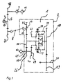
- FIGS. 1 and 2 show schematic diagrams of the power split transmission 1 according to the invention with different structure of the drive elements.
- the power split transmission 1 includes a housing 2 which is mechanically driven via a shaft 8 formed in this example as a propeller shaft.
- a trained as an internal combustion engine drive motor 3 thereby drives a drive shaft 4, on which a gear member 5 is directly attached and meshes with another gear member 24, which in turn drives the shaft 8.
- the gear member 5 is also in operative connection with a gear 12, the gear elements 5, 12, the hydraulic pumps 9 and 14 and designed as a variable displacement hydraulic pump 9 mounted on the power split transmission 1, respectively the housing 2, designed as an adjustment motor, hydraulic motor 16th drives.
- the hydraulic motor 16 can also be arranged within the housing 2 to reduce the installation space and used in this design as a housing-less hydraulic motor 16.
- the housing 2 there is a planetary gear 31, essentially consisting of ring gear 11, planet 30, sun gear 42 and a web 32. Furthermore, the power split transmission 1, respectively the housing 2, the drive shaft 41 for a hydrostatic Operation via the hydraulic motor 16.
- phase of a first driving range with usually low speeds and high traction or torque demand drives the Hydraulic motor 16 to the sun gear 42, wherein a brake 34 is non-positively connected to clamp the ring gear 11 against the housing 2, while another clutch 29 is opened and a further clutch 43 is closed.
- the hydraulic motor 16 drives the sun gear 42 via the gears 26, 22, so that the toothed wheels 18, 19 drive the output shaft 20 via the web 32.
- the couplings 13 likewise introduced in the power split transmission 1 are opened, so that no mechanical power flow can take place via the shaft 8 or the drive shaft 25, for example a propeller shaft, onto the gear 22 likewise present in the power split transmission 1.
- the power split for optimal speed and / or power setting of the drive motor 3 is set by the brake 34 and a further clutch 43 is released and the clutch 13 and the clutch 29 are closed.
- the power of the drive motor 3 on the one hand via the mechanical strand drive shaft 4, gear elements 5 and 24, shaft 8 and drive shaft 25, clutch 13 and gear 22 is directed to the sun gear 42 of the planetary gear 31 and on the other hand power of the drive motor 3 is hydrostatic over the hydraulic pump 9 converted and passed to the hydraulic motor 16, wherein the hydraulic motor 16 now the ring gear 11 via shaft 41, clutch 29, gear 44 and gear 23 drives.
- the performance of the mechanical. Stranges and the hydrostatic power are summed in the planetary gear 31 and directed to the web 32.
- the speeds of the ring gear 11 and the sun gear 42 are in this case added in the manner of a superposition gear and the sum of both speeds results in the planetary gear output speed at the web 32, which determines the speed of the output shaft 20 and the resulting vehicle speed directly proportional.
- the setting of the rotational speed of the ring gear 11 is made via the well-controllable hydraulic motor 16 so that in view of the required vehicle speed, the speed of the sun gear 42 and thus the directly proportional speed of the drive motor 3 in the CVT mode (Continuous Variable Transmission) efficiency - and / or performance optimized.
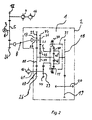
- FIG. 2 shows a different configuration of the drive elements, wherein the driving areas are carried out in the same way as in FIG. 1 described.
- a Reversiernote consisting of a gear 35, a clutch 36 and gears 45,37, provided in the region of the drive shaft 25 to selectively change the direction of rotation of the drive shaft.
Description
- Die Erfindung betrifft ein hydrostatisch mechanisches Leistungsverzweigungsgetriebe gemäß gattungsbildendem Teil des ersten Patentanspruchs.
- Ein hydrostatisch mechanisches Leistungsverzweigungsgetriebe wird beispielsweise in der
DE 10 2004 001 929 A1 beschrieben. Vorgeschlagen wird ein Leistungsverzweigungsgetriebe mit stufenlos veränderlichem Übersetzungsverhältnis, das einen hydrostatischen Getriebeteil, bestehend aus einer ersten Hydrostateinheit mit verstellbarem Volumen und einer zweiten Hydrostateinheit mit konstantem Volumen und einem mechanischen Getriebeteil, umfassend ein Summierungsgetriebe und ein Bereichsgetriebe aufweist, bei dem das Summierungsgetriebe und das Bereichsgetriebe achsversetzt zu den Hydrostateinheiten angeordnet sind. - Die
SU 1504113 A1 - Die
JP 5044816 A - Ein weiteres hydrostatisch mechanisches Leitungsverzweigungsgetriebe ist in der gattungsgemäßen
WO 2009/071060 A2 beschrieben, bestehend aus einem Gehäuse, respektive einem aus einzelnen Gehäuseteilen zusammengesetztem Gehäuse, mindestens eine innerhalb des Gehäuses angeordnete von mindestens einem Antriebsmotor, insbesondere einer Brennkraftmaschine, antreibbare Antriebswelle, die über Zahnradelemente, nach Art eines Pumpenverteilergetriebes, auf mindestens zwei Hydropumpen einwirkt und über mindestens ein weiteres Zahnrad verfügt, das mittel- oder unmittelbar auf ein Abtriebselement eines Lastschaltgetriebes einwirkt, wobei zumindest im Bereich des Zahnrades mindestens ein Kupplungselement positioniert ist, und wobei das Lastschaltgetriebe zumindest eine über mindestens eine, im hydrostatischen Kreislauf antreibbare Welle verfügt, im Bereich derer Kupplungen, Bremsen, Bauteile eines einstufigen Planetengetriebes und dergleichen Bauteile vorgesehen sind, wobei das Abtriebselement des Lastschaltgetriebes auf mindestens eine Ausgangswelle geschaltet ist. Ziel des Erfindungsgegenstandes ist es, ein alternatives hydrostatisch mechanisches Leistungsverzweigungsgetriebe bereit zu stellen, das geeignet ist, Verbrennungsmotoren drehzahloptimiert zu betreiben und gleichzeitig verbesserte Wirkungsgrade dadurch zu erzielen, dass in unterschiedlichen Betriebszuständen jeweils über Kupplungen diejenigen Antriebselemente aktiviert werden, die eine optimale Wirkungsgradbilanz begründen und indem über Kupplungen solche Antriebselemente abgeschaltet und in Stillstand versetzt werden, die in bestimmten Betriebsbereichen funktionell nicht eingesetzt werden, aber den Gesamtwirkungsgrad, z.B. durch Schleppverlust von Hydraulikmotoren, verschlechtern könnten. - Dieses Ziel wird dadurch erreicht, dass die Zahnradelemente über mindestens eine erste Kupplung wahlweise entweder mittel- oder unmittelbar auf ein Sonnenrad eines Planetengetriebes wirken, wobei die Antriebswelle vom Planetengetriebe entkoppelt werden kann, wobei das Planetengetriebe abhängig vom jeweiligen Betriebszustand des Leistungsverzweigungsgetriebes über weitere Kupplungen in einen Zwanglauf schaltbar ist, und wobei der Hydraulikmotor wahlweise über eine zweite Kupplung auf das Sonnenrad und wahlweise über eine dritte Kupplung auf ein Hohlrad des Planetengetriebes koppelbar ist.
- Vorteilhafte Weiterbildungen des Erfindungsgegenstandes sind den zugehörigen Unteransprüchen zu entnehmen.
- Das erfindungsgemäße Getriebe kann mittel- oder unmittelbar von mindestens einem Antriebsmotor, insbesondere einer Brennkraftmaschine, über eine mit mindestens einer Kupplung versehene Antriebswelle angetrieben werden, die mittel- oder unmittelbar wahlweise entweder auf das Sonnenrad des Planetengetriebes geschaltet oder wahlweise kraftunschlüssig geschaltet werden kann, wobei das Planetengetriebe wahlweise über mindestens zwei Kupplungen in einen Zwanglauf geschaltet werden kann. Unter einem Zwanglauf versteht der Fachmann einen Zustand, bei welchem die Bewegung einer der drei Wellen des Planetengetriebes die Bewegung der beiden restlichen Wellen des Planetengetriebes definiert. In der Getriebelehre wird dies nach der "Grüblerschen Gleichung" auch mit dem Laufgrad F=1 beschrieben.
- Die im Bereich des Leistungsverzweigungsgetriebes vorgesehenen Kupplungen/Bremsen, können so betätigt werden, dass das Getriebe wahlweise
- rein hydraulisch mit abgeschalteter mechanischer Antriebswelle
- leistungsverzweigt, d.h. hydraulisch angetrieben und mit mechanisch zugeschalteter Antriebswelle
- rein mechanisch bei wahlweise geschaltetem Zwanglauf des Planetengetriebes und/oder bei wahlweiser Abschaltung des hydrostatischen Leistungszweiges
- Einem Gedanken der Erfindung gemäß ist eine Welle, die vorteilhafterweise als Gelenkwelle ausgebildet ist, unmittelbar vom Antriebsmotor antreibbar.
- Darüber hinaus wird der einzelne Hydraulikmotor wahlweise auf das Sonnenrad und auf das Hohlrad gekoppelt.
- Der Hydraulikmotor kann darüber hinaus über entsprechende Kupplungen vom Planetengetriebe abgekuppelt werden.
- Des Weiteren wird vorgeschlagen, dass der Hydraulikmotor im abgekoppelten Zustand dadurch in den Stillstand versetzt wird, dass die Hydraulikpumpe auf den Fördervolumenstrom Q = 0 l/min geregelt wird.
- Von besonderem Vorteil ist, wenn der Hydraulikmotor und/oder die Hydraulikpumpe innerhalb des Gehäuses angeordnet ist. Dadurch wird eine extrem raumsparende Bauweise des erfindungsmäßen Leistungsverzweigungsgetriebes herbeigeführt.
- Der Erfindungsgegenstand schließt jedoch nicht aus, dass der Hydraulikmotor und/oder die Hydraulikpumpe auch außerhalb des Gehäuses positioniert sein kann, sofern die Einbauverhältnisse, innerhalb eines Fahrzeuges, beispielsweise eines Radladers, dies zu lassen.
- Ist der Hydraulikmotor und/oder die Hydraulikpumpe innerhalb des Gehäuses angeordnet, wird, einem weiteren Gedanken der Erfindung gemäß, vorgeschlagen, den Hydraulikmotor und/oder die Hydraulikpumpe ohne eigenen Gehäusekörper auszubilden. Die beweglichen Antriebselemente des Hydraulikmotors und/oder der Hydraulikpumpe können daher - zur Vermeidung von Planschverlusten-außerhalb eines Gehäuseölsumpfes positioniert werden. Die bei einem Gehäuse für einen Hydraulikmotor und/oder eine Hydraulikpumpe notwendigerweise vorgesehenen Leckölanschlüsse zur Kühlung der beweglichen Antriebselemente sind nunmehr entbehrlich, da Öl aus dem Gehäuseölsumpf verwendet werden kann, mittels welchem die beweglichen Antriebselemente des gehäuselosen Hydraulikmotors und/oder der Hydraulikpumpe angespritzt werden. Durch Vermeidung von Planschverlusten kann eine nicht unerhebliche Erhöhung des Gesamtwirkungsgrades des Leistungsverzweigungsgetriebes herbeigeführt werden.
- Einem weiteren Gedanken der Erfindung gemäß kann der weitere (mechanische) Leistungszweig leistungsadaptiv und/oder drehzahladaptiv und/oder beschleunigungsadaptiv über eine zugehörige Kupplung auf das Sonnenrad geschaltet werden.
- Darüber hinaus wird vorgeschlagen, dass der weitere (mechanische) Leistungszweig dergestalt auf das Sonnenrad schaltbar ist, dass der Verbrennungsmotor verbrauchsoptimiert betrieben werden kann.
- Ebenfalls denkbar ist, dass der Hydraulikmotor leistungsadaptiv und/oder drehzahladaptiv und/oder beschleunigungsadaptiv über eine Kupplung auf das Sonnenrad schaltbar ist.
- Des Weiteren kann es in bestimmten Betriebsbereichen des Fahrzeugs sinnvoll sein, den Hydraulikmotor leistungsadaptiv und/oder drehzahladaptiv und/oder beschleunigungsadaptiv über eine Kupplung auf das Hohlrad zu schalten.
- Da mit dem erfindungsgemäßen Leistungsverzweigungsgetriebe ausgerüstete Fahrzeuge, wie beispielsweise Radlader, Dumper, Trecker oder dergleichen, nicht immer nur vorwärts fahren, wird vorgeschlagen, im Bereich der Antriebswelle eine Reversierstufe vorzusehen, die über eine Kupplung die Drehrichtung des Sonnenrades umkehrt.
- Einem weiteren Gedanken der Erfindung gemäß ist der Hydraulikmotor durch einen Verstellmotor und die Hydraulikpumpe durch eine Verstellpumpe gebildet.
- Von Vorteil kann auch sein, wenn die Hydraulikpumpe mittel- oder unmittelbar vom Antriebsmotor angetrieben wird.
- Darüber hinaus wird vorgeschlagen, dass das Hohlrad des Planetengetriebes über eine Bremse festsetzbar ist, wobei der Steg des Planetengetriebes mittel- oder unmittelbar mit der Abtriebswelle verbunden ist.
- Der Erfindungsgegenstand ist anhand eines Ausführungsbeispiels in der Zeichnung dargestellt und wird wie folgt beschrieben. Es zeigen:
- Figuren 1 und 2
- Prinzipskizzen des erfindungsgemäßen hydrostatisch mechanischen Leistungsverzweigungsgetriebes mit unterschiedlichem Aufbau der Antriebselemente.
- Die
Figuren 1 und2 zeigen Prinzipskizzen des erfindungsgemäßen Leistungsverzweigungsgetriebes 1 mit unterschiedlichem Aufbau der Antriebselemente. - Das Leistungsverzweigungsgetriebe 1 gemäß
Figur 1 beinhaltet ein Gehäuse 2, das über eine in diesem Beispiel als Gelenkwelle ausgebildete Welle 8 mechanisch angetrieben wird. Ein als Brennkraftmaschine ausgebildeter Antriebsmotor 3 treibt dabei eine Antriebswelle 4 an, auf der ein Zahnradelement 5 unmittelbar befestigt ist und mit einem weiteren Zahnradelement 24 kämmt, das wiederum die Welle 8 antreibt. Das Zahnradelement 5 steht darüber hinaus mit einem Zahnrad 12 in Wirkverbindung, wobei die Zahnradelemente 5, 12, die Hydraulikpumpen 9 und 14 und die als Verstellpumpe ausgebildete Hydraulikpumpe 9 den am Leistungsverzweigungsgetriebe 1, respektive dessen Gehäuse 2, montierten, als Verstellmotor ausgebildeten, Hydraulikmotor 16 antreibt. - Der Hydraulikmotor 16 kann zur Reduzierung des Bauraumes auch innerhalb des Gehäuses 2 angeordnet und in dieser Bauform als gehäuseloser Hydraulikmotor 16 eingesetzt werden.
- Innerhalb des Leistungsverzweigungsgetriebes 1, respektive dessen Gehäuse 2, befindet sich ein Planetengetriebe 31, im Wesentlichen bestehend aus Hohlrad 11, Planeten 30, Sonnenrad 42 und einem Steg 32. Weiterhin beinhaltet das Leistungsverzweigungsgetriebe 1, respektive dessen Gehäuse 2, die Antriebswelle 41 für einen hydrostatischen Betrieb über den Hydraulikmotor 16.
- In der Phase eines ersten Fahrbereichs mit üblicherweise niedrigen Geschwindigkeiten und hohem Zugkraft- bzw. Drehmomentbedarf treibt der Hydraulikmotor 16 auf das Sonnenrad 42, wobei eine Bremse 34 kraftschlüssig geschaltet wird, um das Hohlrad 11 gegen das Gehäuse 2 zu klemmen, während eine weitere Kupplung 29 geöffnet und eine weitere Kupplung 43 geschlossen wird. In diesem Betriebszustand treibt der Hydraulikmotor 16 über die Zahnräder 26,22 das Sonnenrad 42 an, so dass über den Steg 32 die Zahnräder 18,19 die Abtriebswelle 20 antreiben. In diesem Betriebszustand ist die gleichfalls im Leistungsverzweigungsgetriebe 1 eingebrachten Kupplungen 13 geöffnet, so dass kein mechanischer Leistungsfluss über die Welle 8 bzw. die Antriebswelle 25, z.B. eine Gelenkwelle, auf das ebenfalls im Leistungsverzweigungsgetriebe 1 vorhandene Zahnrad 22 erfolgen kann. In diesem ersten Fahrbereich, mit niedrigen Geschwindigkeiten und hohem Zugkraft- bzw. Drehmomentbedarf, wird das hohe Drehmomentvermögen der Hydrostaten 9,16 ausgenutzt, sowie deren Möglichkeit der hohen Kraftentfaltung auch bei Drehzahlen im Bereich von n = 0 U/min. Die gute Regelbarkeit der Hydrostaten 9,16 erlaubt es dabei, den Antriebsmotor 3 drehzahl- und leistungsoptimiert zu betreiben.
- Aus diesem Grund treten die bekannten Wirkungsgradnachteile der Hydrostatik, im Vergleich zur Mechanik, im Sinne einer gesamtheitlichen Betrachtung für niedrige Geschwindigkeiten innerhalb dieses ersten Geschwindigkeitsbereiches in den Hintergrund. Bei Erreichen einer hinreichend hohen Drehzahl des Sonnenrades 42 bzw. des Zahnrades 22, wird in diesem ersten Fahrbereich der mechanische Leistungszweig 3 über die Kupplung 13 auf die Zahnräder 21,22 geschaltet und der hydrostatische Leistungszweig 9,16 wird über die Deaktivierung der Kupplung 43 abgeschaltet. In diesem Betriebszustand wird also bereits der erste Fahrbereich das Leistungsverzweigungsgetriebe 1 rein mechanisch betrieben. Zur Erhöhung der Wirkungsgrade wird dabei, abhängig von der benötigten Leistung bzw. des benötigten Drehmoments, der Hydraulikmotor 16 über die Kupplung 43 zur Vermeidung von Schleppverlusten abgeschaltet und stillgesetzt.
- Mit steigender Fahrzeuggeschwindigkeit und daraus resultierendem eingeschränkten Zugkraft- bzw. Drehmomentbedarf wird das hohe Drehmomentvermögen der Hydrostaten 9,16 stetig weniger benötigt, so dass die Hydrostaten 9,16 abhängig von der aktuellen Geschwindigkeit, zurückgeregelt und entkoppelt werden können. Dabei wird zunächst im mittleren Geschwindigkeitsbereich eine Phase der hydrostatisch-mechanischen Leistungsverzweigung eingestellt und im hohen Geschwindigkeitsbereich wird, zur Optimierung der Wirkungsgrade, in einen ausschließlich mechanischen Betrieb übergegangen.
- Im mittleren Geschwindigkeitsbereich wird die Leistungsverzweigung zur optimalen Drehzahl- und/oder Leistungseinstellung des Antriebsmotors 3 eingestellt, indem die Bremse 34 und eine weitere Kupplung 43 gelöst sowie die Kupplung 13 und die Kupplung 29 geschlossen werden. In diesem Betriebszustand wird die Leistung des Antriebsmotors 3 einerseits über den mechanischen Strang Antriebswelle 4, Zahnradelemente 5 und 24, Welle 8 und Antriebswelle 25, Kupplung 13 und Zahnrad 22 auf das Sonnenrad 42 des Planetengetriebes 31 geleitet und anderseits wird Leistung des Antriebsmotors 3 hydrostatisch über die Hydraulikpumpe 9 gewandelt und auf den Hydraulikmotor 16 geleitet, wobei der Hydraulikmotor 16 nun das Hohlrad 11 über Welle 41, Kupplung 29, Zahnrad 44 und Zahnrad 23 antreibt. Die Leistung des mechanischen. Stranges und die hydrostatische Leistung werden dabei im Planetengetriebe 31 summiert und auf den Steg 32 geleitet. Die Drehzahlen des Hohlrades 11 und des Sonnenrades 42 werden hierbei nach Art eines Überlagerungsgetriebes addiert und die Summe beider Drehzahlen ergibt die Planetengetriebe-Ausgangsdrehzahl am Steg 32, die direkt proportional die Drehzahl der Abtriebswelle 20 bzw. die daraus resultierende Fahrzeuggeschwindigkeit bestimmt. Die Einstellung der Drehzahl des Hohlrades 11 wird dabei über den gut regelbaren Hydraulikmotor 16 so vorgenommen, dass mit Blick auf die erforderliche Fahrzeuggeschwindigkeit, die Drehzahl des Sonnenrades 42 und damit die direkt proportionale Drehzahl des Antriebsmotors 3 im CVT-Betrieb (Continous Variable Transmission) wirkungsgrad- und/oder leistungsoptimal eingestellt wird.
- Im letzten und hohen Geschwindigkeitsbereich wird ausschließlich mechanisch angetrieben, indem die Hydrostaten 9,16 leistungsmäßig gegen P = 0 kW gesteuert werden und das Planetengetriebe 31 komplett über die Kupplungen 29 und 43 in einen Zwanglauf versetzt wird. In diesem Betriebsfall wird die Hydraulikpumpe 9 nicht für das Fahren eingesetzt und wahlweise zur Vermeidung von Schleppverlusten über eine nicht dargestellte. Kupplung abgekoppelt.
-
Figur 2 zeigt eine andere Konfiguration der Antriebselemente, wobei die Fahrbereiche in gleicher Weise erfolgen, wie inFigur 1 beschrieben. Zur Realisierung der Rückwärtsfahrt mit dem mechanischem Pfad wird aber zusätzlich eine Reversierstufe, bestehend aus einem Zahnrad 35, einer Kupplung 36 sowie Zahnrädern 45,37, im Bereich der Antriebswelle 25 vorgesehen, um die Drehrichtung der Antriebswelle wahlweise zu ändern.Bezugszeichenliste 1 Leistungsverzweigungsgetriebe 2 Gehäuse 3 Antriebsmotor (Brennkraftmaschine) 29 Kupplung 4 Antriebswelle 30 Planet 5 Zahnradelement 31 Planetengetriebe 32 Steg 8 Welle (Gelenkwelle) 34 Bremse 9 Hydraulikpumpe 35 Zahnrad 36 Kupplung 11 Hohlrad 37 Zahnrad 12 Zahnrad 13 Kupplung 14 Hydraulikpumpe 41 Abtriebswelle 16 Hydraulikmotor 42 Sonnenrad 43 Kupplung 18 Zahnrad 44 Zahnrad 19 Zahnrad 45 Zahnrad 20 Abtriebswelle 21 Zahnrad 22 Zahnrad 23 Zahnrad 24 Zahnradelement 21/22 Zahnradstufe 19/18 Zahnradstufe 25 Antriebswelle 26 Zahnrad
Claims (17)
- Hydrostatisch mechanisches Leitungsverzweigungsgetriebe, beinhaltend ein Gehäuse (2), mindestens einen, aus mindestens einer Hydraulikpumpe (9) und mindestens einem Hydraulikmotor (16) bestehenden ersten Leistungszweig, mindestens eine innerhalb des Gehäuses (2) angeordnete von mindestens einem Antriebsmotor, insbesondere einer Brennkraftmaschine (3) als weiteren Leistungszweig, mittel- oder unmittelbar antreibbare Antriebswelle (25), die über Zahnradelemente (21,22) verfügt, dadurch gekennzeichnet, dass die Zahnradelemente (21, 22) über mindestens eine erste Kupplung (13) wahlweise entweder mittel- oder unmittelbar auf ein Sonnenrad (42) eines Planetengetriebes (31) wirken, wobei die Antriebswelle (25) vom Planetengetriebe (31) entkoppelt werden kann, wobei das Planetengetriebe (31) abhängig vom jeweiligen Betriebszustand des Leistungsverzweigungsgetriebes (1) über weitere Kupplungen (29, 43) in einen Zwanglauf schaltbar ist, und wobei der Hydraulikmotor (16) wahlweise über eine zweite Kupplung (43) auf das Sonnenrad (42) und wahlweise über eine dritte Kupplung (29) auf ein Hohlrad (11) des Planetengetriebes (31) koppelbar ist.
- Leitungsverzweigungsgetriebe nach Anspruch 1 dadurch gekennzeichnet, dass eine Welle (8) direkt, d.h. unmittelbar vom Antriebsmotor (3), antreibbar ist.
- Leitungsverzweigungsgetriebe nach Anspruch 2, dadurch gekennzeichnet, dass die Welle (8) als Gelenkwelle gestaltet ist.
- Leitungsverzweigungsgetriebe nach einem der Ansprüche 1 bis 3, dadurch gekennzeichnet, dass der Hydraulikmotor (16) vom Planetengetriebe (31) abkoppelbar ist.
- Leitungsverzweigungsgetriebe nach einem der Ansprüche 1 bis 4, dadurch gekennzeichnet, dass der Hydraulikmotor (16) im abgekoppelten Zustand dadurch in den Stillstand versetzbar wird, dass die Hydraulikpumpe (9) auf den Fördervolumenstrom Q=0 l/min eingestellt wird.
- Leitungsverzweigungsgetriebe nach einem der Ansprüche 1 bis 5, dadurch gekennzeichnet, dass der Hydraulikmotor (16) innerhalb des Gehäuses (2) angeordnet ist.
- Leitungsverzweigungsgetriebe nach einem der Ansprüche 1 bis 6, dadurch gekennzeichnet, dass der innerhalb des Gehäuses (2) angeordnete Hydraulikmotor (16) keinen eigenen Gehäusekörper aufweist.
- Leitungsverzweigungsgetriebe nach einem der Ansprüche 1 bis 7, dadurch gekennzeichnet, dass die beweglichen Antriebselemente des Hydraulikmotors (16), zur Vermeidung von Planschverlusten, außerhalb eines Gehäuseölsumpfes angeordnet sind.
- Leitungsverzweigungsgetriebe nach einem der Ansprüche 1 bis 8, dadurch gekennzeichnet, dass der weitere Leistungszweig leistungsadaptiv und/oder drehzahladaptiv und/oder beschleunigungsadaptiv über die erste Kupplung (13) auf das Sonnenrad (42) schaltbar ist.
- Leitungsverzweigungsgetriebe nach einem der Ansprüche 1 bis 9, dadurch gekennzeichnet, dass der weitere Leistungszweig dergestalt auf das Sonnenrad (42) schaltbar ist, dass der Verbrennungsmotor (3) verbrauchsoptimiert betrieben wird.
- Leitungsverzweigungsgetriebe nach einem der Ansprüche 1 bis 10, dadurch gekennzeichnet, dass der Hydraulikmotor (16) leistungsadaptiv und/oder drehzahladaptiv und/oder beschleunigungsadaptiv über die zweite Kupplung (43) auf das Sonnenrad (42) schaltbar ist.
- Leitungsverzweigungsgetriebe nach einem der Ansprüche 1 bis 11, dadurch gekennzeichnet, dass der Hydraulikmotor (16) leistungsadaptiv und/oder drehzahladaptiv und/oder beschleunigungsadaptiv über die dritte Kupplung (29) auf das Hohlrad (11) schaltbar ist.
- Leitungsverzweigungsgetriebe nach einem der Ansprüche 1 bis 12, dadurch gekennzeichnet, dass im Bereich der Antriebswelle (25) eine Reversierstufe angeordnet ist, die über eine vierte Kupplung (36) die Drehrichtung des Sonnenrades (42) umkehrt.
- Leistungsverzweigungsgetriebe nach einem der Ansprüche 1 bis 13, dadurch gekennzeichnet, dass der Hydraulikmotor (16) durch einen Verstellmotor und die Hydraulikpumpe (9) durch eine Verstellpumpe gebildet ist.
- Leistungsverzweigungsgetriebe nach einem der Ansprüche 1 bis 14, dadurch gekennzeichnet, dass die Hydraulikpumpe (9) mittel- oder unmittelbar vom Antriebsmotor (3) antreibbar ist.
- Leistungsverzweigungsgetriebe nach einem der Ansprüche 1 bis 15, dadurch gekennzeichnet, dass das Hohlrad (11) des Planetengetriebes (31) über eine Bremse (34) festsetzbar ist.
- Leistungsverzweigungsgetriebe nach einem der Ansprüche 1 bis 16, dadurch gekennzeichnet, dass ein Steg (32) des Planetengetriebes (31) mittel- oder unmittelbar mit einer Abtriebswelle (20) verbunden ist.
Applications Claiming Priority (3)
| Application Number | Priority Date | Filing Date | Title |
|---|---|---|---|
| DE102010056474 | 2010-12-30 | ||
| DE102011102210A DE102011102210A1 (de) | 2010-12-30 | 2011-05-21 | Leistungsverzweigungsgetriebe |
| PCT/DE2011/002148 WO2012089192A1 (de) | 2010-12-30 | 2011-12-20 | Leistungsverzweigungsgetriebe |
Publications (2)
| Publication Number | Publication Date |
|---|---|
| EP2659165A1 EP2659165A1 (de) | 2013-11-06 |
| EP2659165B1 true EP2659165B1 (de) | 2014-10-08 |
Family
ID=45974191
Family Applications (1)
| Application Number | Title | Priority Date | Filing Date |
|---|---|---|---|
| EP11833600.7A Not-in-force EP2659165B1 (de) | 2010-12-30 | 2011-12-20 | Leistungsverzweigungsgetriebe |
Country Status (5)
| Country | Link |
|---|---|
| US (1) | US9109680B2 (de) |
| EP (1) | EP2659165B1 (de) |
| CN (1) | CN103282695B (de) |
| DE (1) | DE102011102210A1 (de) |
| WO (1) | WO2012089192A1 (de) |
Families Citing this family (26)
| Publication number | Priority date | Publication date | Assignee | Title |
|---|---|---|---|---|
| US10670124B2 (en) | 2013-12-31 | 2020-06-02 | Deere & Company | Multi-mode infinitely variable transmission |
| US10655710B2 (en) | 2013-12-31 | 2020-05-19 | Deere & Company | Multi-mode infinitely variable transmission that provides seamless shifting |
| US10647193B2 (en) | 2014-04-09 | 2020-05-12 | Deere & Company | Multi-mode power trains |
| US10738868B2 (en) | 2014-04-09 | 2020-08-11 | Deere & Company | Multi-mode powertrains |
| US10037397B2 (en) * | 2014-06-23 | 2018-07-31 | Synopsys, Inc. | Memory cell including vertical transistors and horizontal nanowire bit lines |
| DE202015004528U1 (de) * | 2015-04-27 | 2016-07-28 | Liebherr-Components Biberach Gmbh | Arbeitsmaschine mit leistungsverzweigbarem Antrieb |
| DE202015102282U1 (de) | 2015-05-05 | 2015-05-18 | Kessler & Co. Gmbh & Co. Kg | Hydrostatisch-mechanisches Leistungsverzweigungsgetriebe |
| CN104948681A (zh) * | 2015-06-16 | 2015-09-30 | 潍柴动力股份有限公司 | 一种液压工程机械的变速装置及其变速器、变速方法 |
| CN106545637A (zh) * | 2016-10-31 | 2017-03-29 | 广西柳工机械股份有限公司 | 动力分配调节系统及装载机动力系统 |
| US10619711B2 (en) | 2017-04-12 | 2020-04-14 | Deere & Company | Infinitely variable transmission with power reverser |
| US11052747B2 (en) | 2018-05-04 | 2021-07-06 | Deere & Company | Multi-mode powertrains |
| US11091018B2 (en) | 2018-05-11 | 2021-08-17 | Deere & Company | Powertrain with variable vertical drop distance |
| US10975959B2 (en) | 2019-04-01 | 2021-04-13 | Deere & Company | Transmission clutch braking control system |
| US11137052B2 (en) | 2019-08-29 | 2021-10-05 | Deere & Company | Transmission assembly with integrated CVP |
| US11351983B2 (en) | 2019-10-31 | 2022-06-07 | Deere & Company | Power control system with transmission transient boost function |
| DE102019132121A1 (de) | 2019-11-27 | 2021-05-27 | Claas Selbstfahrende Erntemaschinen Gmbh | Antriebsstrang für eine landwirtschaftliche Arbeitsmaschine |
| US11846085B2 (en) | 2020-02-17 | 2023-12-19 | Deere & Company | Energy management system for a hybrid vehicle with an electrically powered hydraulic system |
| CN111306279B (zh) * | 2020-02-21 | 2021-08-03 | 江苏大学 | 一种单泵控双马达机械液压复合传动装置 |
| US11325459B2 (en) | 2020-10-09 | 2022-05-10 | Deere & Company | Low profile transmission assembly with integrated CVP |
| US11613246B2 (en) | 2021-01-21 | 2023-03-28 | Deere & Company | Power control system with engine throttle shift function |
| US11628822B2 (en) | 2021-02-09 | 2023-04-18 | Deere & Company | Power control system with stall prevention clutch modulation function |
| US11299141B1 (en) | 2021-02-10 | 2022-04-12 | Deere & Company | System for multi-layer braking and retardation in a work vehicle |
| US11820361B2 (en) | 2021-11-30 | 2023-11-21 | Deere & Company | Transmission assembly with electrical machine unit for improved shift quality |
| US11585412B1 (en) | 2021-12-22 | 2023-02-21 | Deere & Company | Electronically-variable, dual-path power shift transmission for work vehicles |
| US11607948B1 (en) | 2021-12-22 | 2023-03-21 | Deere & Company | Electronically-variable power shift transmission for work vehicles |
| US11913528B1 (en) | 2022-10-28 | 2024-02-27 | Deere & Company | Multi-mode continuously variable transmission assembly with drop set arrangement |
Family Cites Families (19)
| Publication number | Priority date | Publication date | Assignee | Title |
|---|---|---|---|---|
| US3538790A (en) * | 1968-10-02 | 1970-11-10 | Gen Motors Corp | Power train |
| US3709061A (en) * | 1971-02-16 | 1973-01-09 | Urs Syst Corp | Non-regenerative hydromechanical transmission |
| US3714845A (en) * | 1971-08-24 | 1973-02-06 | Gen Motors Corp | Hydromechanical transmission |
| JPS5527983B2 (de) * | 1973-11-28 | 1980-07-24 | ||
| US3918325A (en) * | 1974-01-21 | 1975-11-11 | Clark Equipment Co | Extended range dual-path transmission |
| US4959962A (en) * | 1987-08-27 | 1990-10-02 | Man Nutzfahrzeuge Gmbh | Starter system for automatically turning off and restarting a motor vehicle engine |
| SU1504113A1 (ru) | 1987-12-21 | 1989-08-30 | Производственное объединение "Минский тракторный завод им.В.И.Ленина" | Бесступенчата передача дл трансмиссии самоходной машины |
| JPH0544816A (ja) | 1991-08-09 | 1993-02-23 | Komatsu Ltd | 装輪車両用変速装置 |
| US5890981A (en) * | 1996-11-25 | 1999-04-06 | Caterpillar Inc. | Hydromechanical transmission having three planetaries and five members |
| DE19747459C2 (de) * | 1997-10-27 | 2003-02-06 | Brueninghaus Hydromatik Gmbh | Hydrostatisch-mechanischer Fahrantrieb |
| US5931758A (en) * | 1998-04-08 | 1999-08-03 | General Dynamics Land Systems, Inc. | Simplified multi-range hydromechanical transmission for vehicles |
| US6424902B1 (en) * | 2000-10-30 | 2002-07-23 | Caterpillar Inc. | Method and apparatus for operating a continuously variable transmission in the torque limited region near zero output speed |
| US6565471B2 (en) * | 2000-12-19 | 2003-05-20 | Case Corporation | Continuously variable hydro-mechanical transmission |
| JP4275908B2 (ja) * | 2002-08-02 | 2009-06-10 | 株式会社 神崎高級工機製作所 | 走行作業車のセンター差動装置 |
| JP4570418B2 (ja) * | 2003-09-16 | 2010-10-27 | 株式会社小松製作所 | 油圧−機械式変速装置の制御装置 |
| JP2005114128A (ja) * | 2003-10-10 | 2005-04-28 | Yanmar Co Ltd | 走行作業機における動力伝達装置 |
| DE102004001929A1 (de) | 2004-01-14 | 2005-08-04 | Zf Friedrichshafen Ag | Hydrostatisch-mechanisches Leistungsverzweigungsgetriebe |
| WO2008103298A1 (en) * | 2007-02-16 | 2008-08-28 | Deere & Company | Method for controlling two variable displacement hydrostatic units in an infinitely variable hydro-mechanical transmission |
| DE102007059321A1 (de) * | 2007-12-07 | 2009-06-10 | Hytrac Gmbh | Leistungsverzweigungsgetriebe |
-
2011
- 2011-05-21 DE DE102011102210A patent/DE102011102210A1/de not_active Withdrawn
- 2011-12-20 CN CN201180063655.8A patent/CN103282695B/zh not_active Expired - Fee Related
- 2011-12-20 WO PCT/DE2011/002148 patent/WO2012089192A1/de active Application Filing
- 2011-12-20 EP EP11833600.7A patent/EP2659165B1/de not_active Not-in-force
- 2011-12-20 US US13/995,333 patent/US9109680B2/en not_active Expired - Fee Related
Also Published As
| Publication number | Publication date |
|---|---|
| US20140018201A1 (en) | 2014-01-16 |
| EP2659165A1 (de) | 2013-11-06 |
| CN103282695A (zh) | 2013-09-04 |
| CN103282695B (zh) | 2017-02-15 |
| US9109680B2 (en) | 2015-08-18 |
| WO2012089192A1 (de) | 2012-07-05 |
| DE102011102210A1 (de) | 2012-07-05 |
Similar Documents
| Publication | Publication Date | Title |
|---|---|---|
| EP2659165B1 (de) | Leistungsverzweigungsgetriebe | |
| WO2012095077A1 (de) | Verfahren zur ansteuerung eines hydrostatisch mechanischen leistungsverzweigungsgetriebes | |
| EP2215382B1 (de) | Leistungsverzweigungsgetriebe | |
| EP2466169B1 (de) | Einrichtung für ein Getriebe | |
| DE102010021846A1 (de) | Leistungsverzweigungsgetriebe | |
| AT414345B (de) | Leistungsverzweigungsgetriebe für kraftfahrzeuge | |
| EP0081696B1 (de) | Hydrostatischmechanisches Stellkoppelgetriebe mit eingangsseitiger Leistungsverzweigung | |
| AT11545U1 (de) | Leistungsverzweigungsgetriebe | |
| DE202015102282U1 (de) | Hydrostatisch-mechanisches Leistungsverzweigungsgetriebe | |
| EP2258966A1 (de) | Überlagerungsgetriebe | |
| DE2525888A1 (de) | Leistungsverzweigtes getriebe | |
| EP1325248A1 (de) | Getriebesynthese mit stufenlosen und konstanten getriebemodulen | |
| DE102010029597A1 (de) | Getriebeanordnung | |
| EP1655515B1 (de) | Leistungsverzweigtes hydromechanisches Getriebe mit Summiergetriebemittel | |
| EP0818643B1 (de) | Hydrostatisch-mechanisch leistungsverzweigtes Lastschaltgetriebe | |
| DE4106746A1 (de) | Stufenloses hydrostatisch-mechanisches verzweigungsgetriebe, insbesondere fuer kraftfahrzeuge | |
| DE102007035307A1 (de) | Vorrichtung zur Drehrichtungsumkehr für ein stufenloses hydrostatisch-mechanisches Leistungsverzweigungsgetriebe | |
| EP1565676B1 (de) | Hydrostatischer mehrmotorenantrieb | |
| EP0397804A1 (de) | Lastschaltgetriebe mit stufenlos einstellbarer übersetzung. | |
| EP2215381B1 (de) | Baukastensystem für ein hydrostatisch mechanisches lastschaltgetriebe | |
| DE102021001651B4 (de) | Elektrifiziertes Radien-Überlagerungslenkgetriebe | |
| DE102008015276A1 (de) | Leistungsverzweigungsgetriebe | |
| DE102014105291A1 (de) | Hydro-mechanisches Leistungsverzweigungsgetriebe eines Fahrantriebs | |
| DE102012218912A1 (de) | Getriebe mit einem Grundgetriebe und schaltbarem Nebenabtrieb für einen Schiffsantrieb | |
| DE102019200970B4 (de) | Kraftfahrzeuggetriebe, insbesondere für ein landwirtschaftliches oder kommunales Nutzfahrzeug, sowie Kraftfahrzeugantriebsstrang |
Legal Events
| Date | Code | Title | Description |
|---|---|---|---|
| PUAI | Public reference made under article 153(3) epc to a published international application that has entered the european phase |
Free format text: ORIGINAL CODE: 0009012 |
|
| 17P | Request for examination filed |
Effective date: 20130627 |
|
| AK | Designated contracting states |
Kind code of ref document: A1 Designated state(s): AL AT BE BG CH CY CZ DE DK EE ES FI FR GB GR HR HU IE IS IT LI LT LU LV MC MK MT NL NO PL PT RO RS SE SI SK SM TR |
|
| DAX | Request for extension of the european patent (deleted) | ||
| GRAP | Despatch of communication of intention to grant a patent |
Free format text: ORIGINAL CODE: EPIDOSNIGR1 |
|
| INTG | Intention to grant announced |
Effective date: 20140722 |
|
| GRAS | Grant fee paid |
Free format text: ORIGINAL CODE: EPIDOSNIGR3 |
|
| GRAA | (expected) grant |
Free format text: ORIGINAL CODE: 0009210 |
|
| AK | Designated contracting states |
Kind code of ref document: B1 Designated state(s): AL AT BE BG CH CY CZ DE DK EE ES FI FR GB GR HR HU IE IS IT LI LT LU LV MC MK MT NL NO PL PT RO RS SE SI SK SM TR |
|
| REG | Reference to a national code |
Ref country code: GB Ref legal event code: FG4D Free format text: NOT ENGLISH |
|
| REG | Reference to a national code |
Ref country code: AT Ref legal event code: REF Ref document number: 690813 Country of ref document: AT Kind code of ref document: T Effective date: 20141015 Ref country code: CH Ref legal event code: EP |
|
| REG | Reference to a national code |
Ref country code: IE Ref legal event code: FG4D Free format text: LANGUAGE OF EP DOCUMENT: GERMAN |
|
| REG | Reference to a national code |
Ref country code: DE Ref legal event code: R096 Ref document number: 502011004648 Country of ref document: DE Effective date: 20141120 |
|
| REG | Reference to a national code |
Ref country code: NL Ref legal event code: VDEP Effective date: 20141008 |
|
| REG | Reference to a national code |
Ref country code: LT Ref legal event code: MG4D |
|
| PG25 | Lapsed in a contracting state [announced via postgrant information from national office to epo] |
Ref country code: NL Free format text: LAPSE BECAUSE OF FAILURE TO SUBMIT A TRANSLATION OF THE DESCRIPTION OR TO PAY THE FEE WITHIN THE PRESCRIBED TIME-LIMIT Effective date: 20141008 |
|
| PG25 | Lapsed in a contracting state [announced via postgrant information from national office to epo] |
Ref country code: NO Free format text: LAPSE BECAUSE OF FAILURE TO SUBMIT A TRANSLATION OF THE DESCRIPTION OR TO PAY THE FEE WITHIN THE PRESCRIBED TIME-LIMIT Effective date: 20150108 Ref country code: PT Free format text: LAPSE BECAUSE OF FAILURE TO SUBMIT A TRANSLATION OF THE DESCRIPTION OR TO PAY THE FEE WITHIN THE PRESCRIBED TIME-LIMIT Effective date: 20150209 Ref country code: LT Free format text: LAPSE BECAUSE OF FAILURE TO SUBMIT A TRANSLATION OF THE DESCRIPTION OR TO PAY THE FEE WITHIN THE PRESCRIBED TIME-LIMIT Effective date: 20141008 Ref country code: FI Free format text: LAPSE BECAUSE OF FAILURE TO SUBMIT A TRANSLATION OF THE DESCRIPTION OR TO PAY THE FEE WITHIN THE PRESCRIBED TIME-LIMIT Effective date: 20141008 Ref country code: IS Free format text: LAPSE BECAUSE OF FAILURE TO SUBMIT A TRANSLATION OF THE DESCRIPTION OR TO PAY THE FEE WITHIN THE PRESCRIBED TIME-LIMIT Effective date: 20150208 Ref country code: ES Free format text: LAPSE BECAUSE OF FAILURE TO SUBMIT A TRANSLATION OF THE DESCRIPTION OR TO PAY THE FEE WITHIN THE PRESCRIBED TIME-LIMIT Effective date: 20141008 |
|
| PG25 | Lapsed in a contracting state [announced via postgrant information from national office to epo] |
Ref country code: SE Free format text: LAPSE BECAUSE OF FAILURE TO SUBMIT A TRANSLATION OF THE DESCRIPTION OR TO PAY THE FEE WITHIN THE PRESCRIBED TIME-LIMIT Effective date: 20141008 Ref country code: CY Free format text: LAPSE BECAUSE OF FAILURE TO SUBMIT A TRANSLATION OF THE DESCRIPTION OR TO PAY THE FEE WITHIN THE PRESCRIBED TIME-LIMIT Effective date: 20141008 Ref country code: PL Free format text: LAPSE BECAUSE OF FAILURE TO SUBMIT A TRANSLATION OF THE DESCRIPTION OR TO PAY THE FEE WITHIN THE PRESCRIBED TIME-LIMIT Effective date: 20141008 Ref country code: GR Free format text: LAPSE BECAUSE OF FAILURE TO SUBMIT A TRANSLATION OF THE DESCRIPTION OR TO PAY THE FEE WITHIN THE PRESCRIBED TIME-LIMIT Effective date: 20150109 Ref country code: HR Free format text: LAPSE BECAUSE OF FAILURE TO SUBMIT A TRANSLATION OF THE DESCRIPTION OR TO PAY THE FEE WITHIN THE PRESCRIBED TIME-LIMIT Effective date: 20141008 Ref country code: LV Free format text: LAPSE BECAUSE OF FAILURE TO SUBMIT A TRANSLATION OF THE DESCRIPTION OR TO PAY THE FEE WITHIN THE PRESCRIBED TIME-LIMIT Effective date: 20141008 Ref country code: RS Free format text: LAPSE BECAUSE OF FAILURE TO SUBMIT A TRANSLATION OF THE DESCRIPTION OR TO PAY THE FEE WITHIN THE PRESCRIBED TIME-LIMIT Effective date: 20141008 |
|
| REG | Reference to a national code |
Ref country code: DE Ref legal event code: R097 Ref document number: 502011004648 Country of ref document: DE |
|
| PG25 | Lapsed in a contracting state [announced via postgrant information from national office to epo] |
Ref country code: LU Free format text: LAPSE BECAUSE OF FAILURE TO SUBMIT A TRANSLATION OF THE DESCRIPTION OR TO PAY THE FEE WITHIN THE PRESCRIBED TIME-LIMIT Effective date: 20141220 Ref country code: RO Free format text: LAPSE BECAUSE OF FAILURE TO SUBMIT A TRANSLATION OF THE DESCRIPTION OR TO PAY THE FEE WITHIN THE PRESCRIBED TIME-LIMIT Effective date: 20141008 Ref country code: CZ Free format text: LAPSE BECAUSE OF FAILURE TO SUBMIT A TRANSLATION OF THE DESCRIPTION OR TO PAY THE FEE WITHIN THE PRESCRIBED TIME-LIMIT Effective date: 20141008 Ref country code: EE Free format text: LAPSE BECAUSE OF FAILURE TO SUBMIT A TRANSLATION OF THE DESCRIPTION OR TO PAY THE FEE WITHIN THE PRESCRIBED TIME-LIMIT Effective date: 20141008 Ref country code: DK Free format text: LAPSE BECAUSE OF FAILURE TO SUBMIT A TRANSLATION OF THE DESCRIPTION OR TO PAY THE FEE WITHIN THE PRESCRIBED TIME-LIMIT Effective date: 20141008 Ref country code: SK Free format text: LAPSE BECAUSE OF FAILURE TO SUBMIT A TRANSLATION OF THE DESCRIPTION OR TO PAY THE FEE WITHIN THE PRESCRIBED TIME-LIMIT Effective date: 20141008 |
|
| REG | Reference to a national code |
Ref country code: CH Ref legal event code: PL |
|
| PLBE | No opposition filed within time limit |
Free format text: ORIGINAL CODE: 0009261 |
|
| STAA | Information on the status of an ep patent application or granted ep patent |
Free format text: STATUS: NO OPPOSITION FILED WITHIN TIME LIMIT |
|
| 26N | No opposition filed |
Effective date: 20150709 |
|
| REG | Reference to a national code |
Ref country code: IE Ref legal event code: MM4A |
|
| PG25 | Lapsed in a contracting state [announced via postgrant information from national office to epo] |
Ref country code: CH Free format text: LAPSE BECAUSE OF NON-PAYMENT OF DUE FEES Effective date: 20141231 Ref country code: IE Free format text: LAPSE BECAUSE OF NON-PAYMENT OF DUE FEES Effective date: 20141220 Ref country code: LI Free format text: LAPSE BECAUSE OF NON-PAYMENT OF DUE FEES Effective date: 20141231 |
|
| REG | Reference to a national code |
Ref country code: FR Ref legal event code: PLFP Year of fee payment: 5 |
|
| PG25 | Lapsed in a contracting state [announced via postgrant information from national office to epo] |
Ref country code: SI Free format text: LAPSE BECAUSE OF FAILURE TO SUBMIT A TRANSLATION OF THE DESCRIPTION OR TO PAY THE FEE WITHIN THE PRESCRIBED TIME-LIMIT Effective date: 20141008 |
|
| PG25 | Lapsed in a contracting state [announced via postgrant information from national office to epo] |
Ref country code: SM Free format text: LAPSE BECAUSE OF FAILURE TO SUBMIT A TRANSLATION OF THE DESCRIPTION OR TO PAY THE FEE WITHIN THE PRESCRIBED TIME-LIMIT Effective date: 20141008 |
|
| PG25 | Lapsed in a contracting state [announced via postgrant information from national office to epo] |
Ref country code: MC Free format text: LAPSE BECAUSE OF FAILURE TO SUBMIT A TRANSLATION OF THE DESCRIPTION OR TO PAY THE FEE WITHIN THE PRESCRIBED TIME-LIMIT Effective date: 20141008 |
|
| PG25 | Lapsed in a contracting state [announced via postgrant information from national office to epo] |
Ref country code: BG Free format text: LAPSE BECAUSE OF FAILURE TO SUBMIT A TRANSLATION OF THE DESCRIPTION OR TO PAY THE FEE WITHIN THE PRESCRIBED TIME-LIMIT Effective date: 20141008 |
|
| PG25 | Lapsed in a contracting state [announced via postgrant information from national office to epo] |
Ref country code: TR Free format text: LAPSE BECAUSE OF FAILURE TO SUBMIT A TRANSLATION OF THE DESCRIPTION OR TO PAY THE FEE WITHIN THE PRESCRIBED TIME-LIMIT Effective date: 20141008 Ref country code: HU Free format text: LAPSE BECAUSE OF FAILURE TO SUBMIT A TRANSLATION OF THE DESCRIPTION OR TO PAY THE FEE WITHIN THE PRESCRIBED TIME-LIMIT; INVALID AB INITIO Effective date: 20111220 Ref country code: MT Free format text: LAPSE BECAUSE OF FAILURE TO SUBMIT A TRANSLATION OF THE DESCRIPTION OR TO PAY THE FEE WITHIN THE PRESCRIBED TIME-LIMIT Effective date: 20141008 |
|
| REG | Reference to a national code |
Ref country code: FR Ref legal event code: PLFP Year of fee payment: 6 |
|
| REG | Reference to a national code |
Ref country code: FR Ref legal event code: PLFP Year of fee payment: 7 |
|
| REG | Reference to a national code |
Ref country code: AT Ref legal event code: MM01 Ref document number: 690813 Country of ref document: AT Kind code of ref document: T Effective date: 20161220 |
|
| PG25 | Lapsed in a contracting state [announced via postgrant information from national office to epo] |
Ref country code: AT Free format text: LAPSE BECAUSE OF NON-PAYMENT OF DUE FEES Effective date: 20161220 |
|
| PG25 | Lapsed in a contracting state [announced via postgrant information from national office to epo] |
Ref country code: MK Free format text: LAPSE BECAUSE OF FAILURE TO SUBMIT A TRANSLATION OF THE DESCRIPTION OR TO PAY THE FEE WITHIN THE PRESCRIBED TIME-LIMIT Effective date: 20141008 |
|
| PG25 | Lapsed in a contracting state [announced via postgrant information from national office to epo] |
Ref country code: AL Free format text: LAPSE BECAUSE OF FAILURE TO SUBMIT A TRANSLATION OF THE DESCRIPTION OR TO PAY THE FEE WITHIN THE PRESCRIBED TIME-LIMIT Effective date: 20141008 |
|
| PGFP | Annual fee paid to national office [announced via postgrant information from national office to epo] |
Ref country code: DE Payment date: 20191210 Year of fee payment: 9 |
|
| PGFP | Annual fee paid to national office [announced via postgrant information from national office to epo] |
Ref country code: BE Payment date: 20191219 Year of fee payment: 9 Ref country code: IT Payment date: 20191230 Year of fee payment: 9 Ref country code: FR Payment date: 20191220 Year of fee payment: 9 |
|
| PGFP | Annual fee paid to national office [announced via postgrant information from national office to epo] |
Ref country code: GB Payment date: 20191220 Year of fee payment: 9 |
|
| REG | Reference to a national code |
Ref country code: DE Ref legal event code: R119 Ref document number: 502011004648 Country of ref document: DE |
|
| GBPC | Gb: european patent ceased through non-payment of renewal fee |
Effective date: 20201220 |
|
| REG | Reference to a national code |
Ref country code: BE Ref legal event code: MM Effective date: 20201231 |
|
| PG25 | Lapsed in a contracting state [announced via postgrant information from national office to epo] |
Ref country code: FR Free format text: LAPSE BECAUSE OF NON-PAYMENT OF DUE FEES Effective date: 20201231 Ref country code: IT Free format text: LAPSE BECAUSE OF NON-PAYMENT OF DUE FEES Effective date: 20201220 |
|
| PG25 | Lapsed in a contracting state [announced via postgrant information from national office to epo] |
Ref country code: DE Free format text: LAPSE BECAUSE OF NON-PAYMENT OF DUE FEES Effective date: 20210701 Ref country code: GB Free format text: LAPSE BECAUSE OF NON-PAYMENT OF DUE FEES Effective date: 20201220 |
|
| PG25 | Lapsed in a contracting state [announced via postgrant information from national office to epo] |
Ref country code: BE Free format text: LAPSE BECAUSE OF NON-PAYMENT OF DUE FEES Effective date: 20201231 |