EP2658413B1 - Erwärmungsapplikatorsystem für durch wärme zersetzungsfähige produkte - Google Patents
Erwärmungsapplikatorsystem für durch wärme zersetzungsfähige produkte Download PDFInfo
- Publication number
- EP2658413B1 EP2658413B1 EP11852384.4A EP11852384A EP2658413B1 EP 2658413 B1 EP2658413 B1 EP 2658413B1 EP 11852384 A EP11852384 A EP 11852384A EP 2658413 B1 EP2658413 B1 EP 2658413B1
- Authority
- EP
- European Patent Office
- Prior art keywords
- reservoir
- subassembly
- applicator head
- heat generating
- generating portion
- Prior art date
- Legal status (The legal status is an assumption and is not a legal conclusion. Google has not performed a legal analysis and makes no representation as to the accuracy of the status listed.)
- Active
Links
Images









Classifications
-
- A—HUMAN NECESSITIES
- A45—HAND OR TRAVELLING ARTICLES
- A45D—HAIRDRESSING OR SHAVING EQUIPMENT; EQUIPMENT FOR COSMETICS OR COSMETIC TREATMENTS, e.g. FOR MANICURING OR PEDICURING
- A45D40/00—Casings or accessories specially adapted for storing or handling solid or pasty toiletry or cosmetic substances, e.g. shaving soaps or lipsticks
- A45D40/26—Appliances specially adapted for applying pasty paint, e.g. using roller, using a ball
-
- A—HUMAN NECESSITIES
- A45—HAND OR TRAVELLING ARTICLES
- A45D—HAIRDRESSING OR SHAVING EQUIPMENT; EQUIPMENT FOR COSMETICS OR COSMETIC TREATMENTS, e.g. FOR MANICURING OR PEDICURING
- A45D40/00—Casings or accessories specially adapted for storing or handling solid or pasty toiletry or cosmetic substances, e.g. shaving soaps or lipsticks
- A45D40/26—Appliances specially adapted for applying pasty paint, e.g. using roller, using a ball
- A45D40/262—Appliances specially adapted for applying pasty paint, e.g. using roller, using a ball using a brush or the like
-
- A—HUMAN NECESSITIES
- A45—HAND OR TRAVELLING ARTICLES
- A45D—HAIRDRESSING OR SHAVING EQUIPMENT; EQUIPMENT FOR COSMETICS OR COSMETIC TREATMENTS, e.g. FOR MANICURING OR PEDICURING
- A45D34/00—Containers or accessories specially adapted for handling liquid toiletry or cosmetic substances, e.g. perfumes
- A45D34/04—Appliances specially adapted for applying liquid, e.g. using roller or ball
-
- A—HUMAN NECESSITIES
- A45—HAND OR TRAVELLING ARTICLES
- A45D—HAIRDRESSING OR SHAVING EQUIPMENT; EQUIPMENT FOR COSMETICS OR COSMETIC TREATMENTS, e.g. FOR MANICURING OR PEDICURING
- A45D40/00—Casings or accessories specially adapted for storing or handling solid or pasty toiletry or cosmetic substances, e.g. shaving soaps or lipsticks
- A45D40/0087—Casings or accessories specially adapted for storing or handling solid or pasty toiletry or cosmetic substances, e.g. shaving soaps or lipsticks for samples
-
- A—HUMAN NECESSITIES
- A45—HAND OR TRAVELLING ARTICLES
- A45D—HAIRDRESSING OR SHAVING EQUIPMENT; EQUIPMENT FOR COSMETICS OR COSMETIC TREATMENTS, e.g. FOR MANICURING OR PEDICURING
- A45D40/00—Casings or accessories specially adapted for storing or handling solid or pasty toiletry or cosmetic substances, e.g. shaving soaps or lipsticks
- A45D40/18—Casings combined with other objects
-
- A—HUMAN NECESSITIES
- A45—HAND OR TRAVELLING ARTICLES
- A45D—HAIRDRESSING OR SHAVING EQUIPMENT; EQUIPMENT FOR COSMETICS OR COSMETIC TREATMENTS, e.g. FOR MANICURING OR PEDICURING
- A45D40/00—Casings or accessories specially adapted for storing or handling solid or pasty toiletry or cosmetic substances, e.g. shaving soaps or lipsticks
- A45D40/26—Appliances specially adapted for applying pasty paint, e.g. using roller, using a ball
- A45D40/262—Appliances specially adapted for applying pasty paint, e.g. using roller, using a ball using a brush or the like
- A45D40/265—Appliances specially adapted for applying pasty paint, e.g. using roller, using a ball using a brush or the like connected to the cap of the container
-
- A—HUMAN NECESSITIES
- A46—BRUSHWARE
- A46B—BRUSHES
- A46B11/00—Brushes with reservoir or other means for applying substances, e.g. paints, pastes, water
- A46B11/0003—Brushes with reservoir or other means for applying substances, e.g. paints, pastes, water containing only one dose of substance, e.g. single-use toothbrushes
-
- A—HUMAN NECESSITIES
- A46—BRUSHWARE
- A46B—BRUSHES
- A46B13/00—Brushes with driven brush bodies or carriers
- A46B13/001—Cylindrical or annular brush bodies
- A46B13/003—Cylindrical or annular brush bodies made up of a series of annular brush rings; Annular brush rings therefor
-
- A—HUMAN NECESSITIES
- A46—BRUSHWARE
- A46B—BRUSHES
- A46B15/00—Other brushes; Brushes with additional arrangements
- A46B15/0002—Arrangements for enhancing monitoring or controlling the brushing process
- A46B15/0016—Arrangements for enhancing monitoring or controlling the brushing process with enhancing means
- A46B15/003—Enhancing with heat
-
- A—HUMAN NECESSITIES
- A46—BRUSHWARE
- A46B—BRUSHES
- A46B7/00—Bristle carriers arranged in the brush body
- A46B7/04—Bristle carriers arranged in the brush body interchangeably removable bristle carriers
-
- H—ELECTRICITY
- H05—ELECTRIC TECHNIQUES NOT OTHERWISE PROVIDED FOR
- H05B—ELECTRIC HEATING; ELECTRIC LIGHT SOURCES NOT OTHERWISE PROVIDED FOR; CIRCUIT ARRANGEMENTS FOR ELECTRIC LIGHT SOURCES, IN GENERAL
- H05B3/00—Ohmic-resistance heating
- H05B3/20—Heating elements having extended surface area substantially in a two-dimensional [2D] plane, e.g. plate-heater
- H05B3/22—Heating elements having extended surface area substantially in a two-dimensional [2D] plane, e.g. plate-heater non-flexible
- H05B3/26—Heating elements having extended surface area substantially in a two-dimensional [2D] plane, e.g. plate-heater non-flexible heating conductor mounted on insulating base
-
- A—HUMAN NECESSITIES
- A45—HAND OR TRAVELLING ARTICLES
- A45D—HAIRDRESSING OR SHAVING EQUIPMENT; EQUIPMENT FOR COSMETICS OR COSMETIC TREATMENTS, e.g. FOR MANICURING OR PEDICURING
- A45D2200/00—Details not otherwise provided for in A45D
- A45D2200/15—Temperature
- A45D2200/155—Heating or cooling means, i.e. for storing or applying cosmetic products at a predetermined temperature
-
- A—HUMAN NECESSITIES
- A45—HAND OR TRAVELLING ARTICLES
- A45D—HAIRDRESSING OR SHAVING EQUIPMENT; EQUIPMENT FOR COSMETICS OR COSMETIC TREATMENTS, e.g. FOR MANICURING OR PEDICURING
- A45D2200/00—Details not otherwise provided for in A45D
- A45D2200/15—Temperature
- A45D2200/155—Heating or cooling means, i.e. for storing or applying cosmetic products at a predetermined temperature
- A45D2200/157—Heating means for mascara applicators
-
- A—HUMAN NECESSITIES
- A46—BRUSHWARE
- A46B—BRUSHES
- A46B2200/00—Brushes characterized by their functions, uses or applications
- A46B2200/10—For human or animal care
- A46B2200/1046—Brush used for applying cosmetics
- A46B2200/1053—Cosmetics applicator specifically for mascara
Definitions
- the present invention is in the field of cosmetic and personal care products.
- the present invention concerns a heating applicator system for mascara or other products that tend to dry out or be adversely affected when heated.
- Heating mascara applicators have only recently begun to appear on the market, and their presence in the marketplace may grow significantly in years to come.
- US12/980,526 we explained that one impediment to market acceptance is lack of familiarity with heated mascara application, and we described a system for sampling a heated product at a store counter.
- the present application we tackle another impediment to market acceptance; the problem of product dry-out as a result of repeated exposure to heat.
- Full size, salable mascara products may typically supply about 4g to about 10g of mascara. If a single use includes making up two eyes, then many full size saleable mascara products are used 100 times or more, before being discarded.
- a main object of the present invention is to provide a heating applicator system and a saleable amount of cosmetic or personal care product, that alleviates the problems associated with heat exposure in the reservoir and on the applicator head.
- the present invention comprises a set of disposable first subassemblies (designated FS) and at least on reusable second subassembly (designated SS).
- Each first subassembly comprises a reservoir of product and an applicator head that is initially mounted in the reservoir. The mounting of the applicator head seals the reservoir and protects the product in the reservoir prior to use.
- the reusable second subassembly comprises a handle, a heat generating portion, and a power source. The second subassembly is able to be attached to and detached from the first subassembly.
- the heat generating portion is disposed inside the applicator head for heating product in the reservoir and/or on the applicator head.
- the applicator head can be removed from its mounting in the reservoir so that the applicator head becomes associated with the second subassembly.
- the product in the reservoir is used up, then the reusable second subassembly can be detached from the applicator head.
- the applicator head and exhausted reservoir are disposed, while the second subassembly is reused with another first subassembly.
- Process application temperature means a temperature of the product that is greater than ambient temperature, at which some characteristic of the product is enhanced or improved.
- ambient temperature may be taken to be 20°C to 25°C
- product application temperature may be 30°C or greater, or 40°C or greater, or 50°C or greater, or 60°C or greater, and so on, as the situation dictates.
- the improved characteristic may relate to application of the product to the skin or hair, or it may relate to the performance or shelf life of the product.
- the improved characteristic may relate to a consumer's experience or expectation of the product.
- the characteristic improvement may be a pre-defined reduction in viscosity. Or, for example, it may be activation of an active ingredient above a threshold temperature. Or, for example, the improved characteristic may be longer shelf life due to a reduction in harmful microbes in the product. Or the improved characteristic may be a feeling of warmth, experienced by the consumer.
- Handheld applicator means an applicator that is intended to be held in one hand, or at most two hands, and raised in the air as the applicator is performing one or more main activities. Main activities include using the applicator to transfer product from the reservoir to an application surface.
- Handheld means more than just being able to grasp an object. For example, a "space heater” does not meet this definition of handheld.
- electrical contact means that, if a potential difference is provided between electronic elements, then an electric current is able to flow between those elements, whether there is direct physical contact between the elements or whether one or more other conductive elements intervene.
- fluid tight we mean a seal that is sufficiently tight to prevent product from leaking out of the reservoir, and sufficiently tight to slow down the degradation of product in the reservoir.
- the fluid tight seal also means that the seal is able to prevent oxidation of a product in the reservoir.
- prevent oxidation we mean that the product remains in a saleable condition (as a person of ordinary skill in the art would understand “saleable condition") for a period of at least six months, preferably for a period of at least one year, at standard temperature and pressure.
- a disposable first subassembly that comprises a reservoir that is capable of holding a product, a neck extension that is connected to the reservoir in a detachable/reattachable manner, and an applicator head that depends from the neck extension into the reservoir.
- a portion of the neck extension seals off the product in the reservoir from the ambient atmosphere outside of the first subassembly. From outside the first subassembly, a conduit exists through the neck extension and into an interior space of the applicator head.
- Another aspect of the present invention that is common to several embodiments is a reusable second subassembly (SS) that is separable from the first subassembly, but which must be attached to the first subassembly at the time of use.
- the second subassembly comprises a handle, an electric circuit housing, an electric heating circuit, an on-off mechanism, and a power source. Taken together, a first and second subassembly make up a heating applicator system according to the present invention.
- the electric circuit housing of the second subassembly (SS) and the neck extension of the first subassembly (FS) are able to form a sufficiently rigid connection.
- a portion of the electric heating circuit is inserted through the neck extension and into the interior space of the applicator head.
- the neck extension and applicator head can be separated from the reservoir for use in applying the product.
- the neck extension with applicator head may be reattached to the reservoir to seal it off.
- the electric circuit housing and neck extension can be separated, so that the second subassembly can be reused, while the components of the first subassembly are discarded.
- the multiple-use reservoir of the present invention is able to be resealed to protect the product remaining in the reservoir.
- the first subassembly is still considered to be "disposable", because after the contents of the reservoir are exhausted, it cannot be reused.
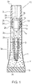
- the disposable first subassembly comprises a reservoir (1), a neck extension (2) that is connected to the reservoir in a detachable/reattachable manner, and an applicator head (3) that depends from the neck extension into the reservoir.
- the first subassembly is considered as "disposable" because after a user has exhausted the contents of the reservoir, the reservoir, neck extension and applicator head are disposed.
- the reservoir (1) holds or is able to hold a product (P).
- the reservoir may typically be cylindrical or have a cylindrical portion, and be fully or partly made of plastic, but this is not required.
- the reservoir is depicted as a plastic tube.
- the reservoir has a top end that may preferably be in the form of a hollow neck (1a), and a bottom end (1b).
- An upper orifice (1c) located in the top end of the reservoir offers access to the interior of the neck and reservoir.
- the neck of the reservoir is connected to a neck extension.
- the bottom end (1b) of the reservoir (1) may be closed before or after filling the reservoir with product, depending on the type of reservoir.
- the reservoir is a rigid bottle for holding mascara
- the bottom of the reservoir will be closed when the bottle is molded.
- the reservoir is filled through the upper orifice (1c) located in the neck (1a) of the reservoir.
- the bottom end of the reservoir is initially opened for filling product into the reservoir, and subsequently closed.
- the reservoir is a flexible tube, it is possible to assemble the first subassembly, and then fill the reservoir through the bottom end of the tube. Thereafter, the bottom end of the tube can be sealed according to known methods, such as heat welding or sonic welding.
- a down-turned portion (1e) is integrally molded with and depends from the perimeter of the lower end of the neck (1a) into the reservoir.
- This down-turned portion defines a lower orifice (1g) of the neck.
- the lower orifice is sufficiently large to allow an applicator head to pass there-through, but sufficiently small so that the down-turned portion acts as a wiper element for the applicator head.
- the down-turned portion may be conical, as shown.
- the height of the conical down-turned portion may be varied as needed to effectively clean the applicator head.
- this wiper element may be significantly shorter than conventional wiper elements because the system of the present invention is intended to be used for relatively fewer applications.
- the issues of messy product build up and dry-out are not relevant, or not as relevant, as with full size saleable mascara packages.
- the Neck Extension Referring again to figure 1 , the neck (1 a) of the reservoir (1) is connected to a hollow neck extension (2), such that the orifice (1 c) of the reservoir is surrounded by the neck extension.
- the neck extension has a top end (2a) and a bottom end (2b), and a passageway exists through the neck extension between the top and bottom ends. Nearer the bottom end, an interior surface of the neck extension has a means of connecting to the neck (1a) of the reservoir.
- the connection between the reservoir neck and the neck extension is preferably detachable and reattachable, as this is how the product in the reservoir is accessed.
- the two components are attached, they maintain a fluid tight connection to prevent dry-out of the product in the reservoir.
- the neck extension has threads (2d) formed on its interior surface, which cooperate with threads (1d) located on an exterior surface of the reservoir neck (1a).
- threads (1d) located on an exterior surface of the reservoir neck (1a).
- the reservoir and neck extension may be connected by an interference engagement (i.e. friction fitting, snap fitment, lug fitment) that can be overcome and reengaged by manual pressure.
- the neck extension may be sized fit inside the reservoir or vice versa.
- the neck extension (2) further comprises a means for connecting the first and second subassemblies.
- the connection between subassemblies is detachable so that the second subassembly can be reused with a different first subassembly.
- connection means may be a second set of threads formed on an interior surface of the neck extension, which cooperate with threads located on an exterior surface of the second subassembly. By means of screwing and unscrewing, the first and second subassemblies could be attached and detached.
- the connection between the first and second subassemblies is implemented as at least one bayonet style or lug style locking mechanism.
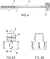
- the neck extension (2) may be provided with a transit groove (2e) on its interior surface that extends downward from the top end (2a) of the neck extension, and terminates in a locking groove (2f), which may extend at an approximately right angle to the transit groove. More than one set of transit and locking grooves may be provided. For each set of grooves, a cooperating lug (5d) located on an exterior surface of the second subassembly is able to travel down the transit groove, and enter into the locking groove, from which it cannot back out without some manual effort. The limited amount of rotation (i.e.
- first and second subassemblies may be connected by some other interference engagement (i.e. friction fitting, snap fitment, cam-and-groove coupling, lug-style coupling, etc.) that can be disengaged and reengaged by manual effort.
- interference engagement i.e. friction fitting, snap fitment, cam-and-groove coupling, lug-style coupling, etc.
- An applicator head (3) comprises a hollow stem (3b), that has an opened proximal portion (3c) and a closed distal portion (3d).
- the closed distal portion supports a working surface (3a).
- a typical form of the working surface may be a bristle brush, such as those used for eyelash makeup and grooming, but the invention is not so limited.
- the hollow stem (3b) articulates with the neck extension (2), preferably forming a fluid tight seal.
- the opened proximal portion (3c) of the hollow stem may be shaped complementarily to the L-shaped portion (2c) of the neck extension, and sized to fit snugly into the L-shaped portion.
- the neck extension and applicator head could be integrally molded.
- the opened proximal portion (3c) of the applicator head (3) and the L-shaped portion (2c) of the neck extension (2) do not separate during normal consumer use.
- the neck extension and applicator head act as one unit.
- the opened proximal portion could be bonded to the interior of the L-shaped portion with adhesive.
- the neck extension and applicator head could be integrally molded.
- the product (P) in the reservoir is sealed off from the ambient environment, and the working surface (3a) of the applicator head is immersed in the product. Furthermore, when the reservoir, neck extension, and applicator head are assembled, a passage exists through the top end (2a) of the neck extension, through the interior of the neck extension, through the opened proximal portion (3c) of the applicator head, and into the closed distal portion (3d) of the applicator head. Thus the interior of the applicator head is accessible from outside of the first subassembly. For example, when the first subassembly is assembled, the applicator head is still able to receive into itself a heat generating portion.
- the neck extension (2) and the applicator head (3) can be repeatedly connected to, and disconnected from the reservoir (1), such that when connected, the applicator head is disposed in the reservoir, and the connection is fluid tight, as defined above. Furthermore, what is essential is that the neck extension is able to temporarily connect to a second subassembly such that, when connected, a heat generating portion is disposed inside the applicator head.
- the second subassembly comprises a handle, a heating circuit housing, a switchable electric heating circuit, and one or more means of engaging the electric heating circuit.
- the second subassembly is considered as "reusable" because even after a user has disposed of the first subassembly, the second subassembly can be reused with a new first subassembly.
- the handle (4) is shown as a hollow cylindrical structure, but the shape may vary. In general, the handle is large enough to be grasped by a user of personal care products, as is typically done in the field.
- the handle may be part of a mascara applicator that is from 15mm to 150mm in length, and from 10mm to 50mm in diameter.
- a proximal end (4a) of the handle (4) defines the proximal end of the second subassembly.
- the proximal end is closed, but may have a removable cap (not shown) at its proximal end.
- the removable cap would offer access to the interior of the handle, and/or access to a power source/current source (8) for changing the power source/current source, for example.
- Opposite the proximal end of the handle is a distal, opened end (4b).
- the handle does not generally act as a closure for the container, as is commonly done in the art.
- the interior of the handle is sufficiently large to accommodate a power source (8), and a portion of the switchable electric heating circuit.
- a first and second metallic leads (4d, 4e) may be attached to an inner surface of the handle, such that the leads are able conduct electricity from a heat generating portion toward the negative terminal of the current source.
- the second metallic lead is formed as a spring, which, in a compressed state, urges the current source toward the opened end (4b) of the handle.
- the upper end of the spring (4e) is attached to a conductive plate (4c) which provides a flat surface for making sure electrical contact with the spring.
- the power source may be rechargeable.
- the handle (4) may be provided with a removable cap(not shown), which would allow the power source (i.e. a battery) to be removed from the handle for recharging.
- the exterior of the handle is provided with recharging leads that allow a battery to be connected to an external power reservoir.
- the recharging leads must be such that when the external power reservoir is connected, a recharging circuit is completed that is effective to transmit power from the external power reservoir to a battery for storage.
- recharging leads (4f and 4g) are accessible from outside of the handle (4).
- Recharging lead (4f) connects to the negative terminal of a battery through conductive plate (4c) and spring (4e), while recharging lead (4g) is sometimes connected to the positive terminal of the battery through recharging lead (4h).
- Recharging lead (4h) is welded to the positive terminal of the battery so that the lead moves with up and down with the battery. As it moves up, recharging lead (4h) makes contact with recharging lead (4g), making it possible to recharge the battery if the device is disposed into a recharging base. As it moves down, recharging lead (4h) breaks contact with recharging lead (4g), in which condition it is impossible to recharge the battery.
- semi-circular forms (4i, 4j) may be provided to secure recharging leads (4f, 4g) in a fixed configuration.
- the semi-circular forms are mated to the interior shape of the handle (4) such that, once assembled, the forms do not move.
- the recharging leads are sandwiched between the semicircular forms which are molded to receive the shape of the recharging leads.
- the exterior of the handle may be provided with a mean of registering each recharging lead (4f, 4g) with the appropriate recharging contact (see below) of a recharging base.
- a handle could be designed with a raised element (4k) that is mated to a slot in a recharging base, so that the handle fits into the recharging base in only one orientation.
- the heating circuit housing and the handle may be fitted with one or more of: an interference fit, a catch mechanism, adhesive, or any suitable means, depending on the nature of the connection, to be discussed below.
- a Heating Circuit Housing In its essential features, a heating circuit housing (5) is a hollow, elongated member that is opened near its upper (5a) and lower (5b) ends, to permit a portion of the electric heating circuit to be reposed through it, with portions of the electric heating circuit emerging from both ends of the housing.
- the housing does not move substantially in relation to the handle (4) with which it articulates.
- Some embodiments of the present invention have a heating circuit housing (5) as shown in figures 3A and 3B .
- An upper portion of the heating circuit housing is situated inside the handle (4) such that the housing does not move substantially in relation to the handle. Any suitable means of securing the heating circuit housing against unwanted motion relative to the handle may be used.
- a portion of the housing may be shaped complimentarily to an interior portion of the handle.
- the upper end (5a) of the housing is formed as a roughly cylindrical portion that fits snugly within a cylindrical interior of the handle.
- detents (5c) in the housing for forming a snap fitment to handle may also be provided.
- At least one vertical groove (5e) is provided near the upper end (5a) of the heating circuit housing (5), while one or more vertical extensions (5f) rise above the upper end.
- the upper end (5a) of the housing is formed as a roughly cylindrical portion that is partly hollow and opened near the bottom of the cylindrical portion. In this way, threads (5g), disposed on the interior of the cylindrical portion may be engaged.
- the lower end (5b) of the heating circuit housing (5) is able to form a rigid connection to the neck extension (2), thus joining the first and second subassemblies.
- the lower end of the housing is a separate component that snap fits into the main component of the housing, as shown.
- the connection between subassemblies is detachable so that the second subassembly can be reused with a different first subassembly.
- Various connection means were discussed above.
- a Switchable Electric Heating Circuit The system for sampling a heated product further comprises an interruptible or switchable electric heating circuit.
- a switch in the circuit when a switch in the circuit is closed, current flows to a heat generating portion, and this defines the heat generating portion as "on”. When this switch is opened, current is not flowing to the heat generating portion, and this defines the heat generating portion as "off”.
- the heating circuit When the heating circuit is closed, current flows from the positive terminal of a power source (8), through the heating circuit housing (5), then to a heat generating portion that is capable of being located inside the applicator head (3), back through the heating circuit housing, along one or more leads to a negative terminal of the power source.
- the electrical path may comprise various electric components that add functionality and/or efficiency to the circuit.
- a switchable electric heating circuit comprises a printed circuit board (PCB) (7), a battery (8), a switch which may or may not be mounted on the PCB, and one or more electrical conductors that are not on the PCB.
- PCB printed circuit board
- the electric circuit housing (5) is a housing for the printed circuit board, and may be referred to as the PCB housing.
- a printed circuit board (7) is an elongated structure that passes through the PCB housing (5) such that portions of the PCB emerge from either end of the PCB housing.
- An enlarged portion (7a) of the PCB is situated inside the handle (4), near a battery.
- a lower portion (7b) of the printed circuit board supports a heat generating portion (7c). The heat generating portion must be able to fit into the hollow stem (3b) of the applicator head (3).
- the bulk of the electronic circuitry is carried on the printed circuit board.
- the printed circuit board comprises a substrate (7d) that is non-conductive to electricity under the conditions of normal or expected use. Suitable substrate materials include, but are not limited to, epoxy resin, glass epoxy, Bakelite (a thermosetting phenol formaldehyde resin), and fiberglass.
- the substrate may be about 0.25 to 5.0mm thick, preferably 0.5 to 3mm, more preferably, 0.75 to 1.5mm thick. Portions of one or both sides of the substrate may be covered with a layer of copper, for example, about 35 ⁇ m thick.
- the substrate supports one or more heat generating portions, electronic components and conductive elements. Among the conductive elements supported by the PCB, are electrical leads and/or terminals that that are effective to connect the PCB to a battery.
- a printed circuit board (7) will be described that supports various elements in a preferred (but not exclusive) arrangement.
- the PCB itself may have any shape or dimensions that are convenient to manufacture and assemble into the PCB housing (5), with the requirement that the PCB is able to extend from the electric current source (8), to a distance beyond the distal end of the PCB housing. This distance depends on the overall length and design of the system. In general, the PCB cannot be so long that it would bottom out in the applicator head (3) before the PCB housing and neck extension (2) form a rigid connection.
- all or most of the electronic elements or components except the resistive heating element(s) (7c) may be located on the enlarged portion (7a) of the printed circuit board, near the upper end of the board.
- the largest lateral dimension of the enlarged portion of the PCB must be less than an interior dimension of that part of the handle (4) in which it resides.
- a relatively narrow, elongated section (7e) of the PCB extends from the enlarged portion, through the PCB housing (5), and emerges from the lower end of the PCB housing.
- none of the heat generating portion is inside the PCB housing, as this would tend to reduce the heating efficiency of the system.
- Figure 6 shows one possible electronic circuit useful in the present invention, which could be laid out on a printed circuit board (7).
- Figure 5 shows one possible layout of electronic elements on the PCB.
- Electric current from a power source (8) enters the printed circuit board at a PCB terminal (T1).
- This terminal may occupy an edge of an enlarged portion (7a) of the PCB.
- the positive terminal of the battery (8) may alternately occupy at least one "on” position and at least one "off' position, according to the positioning of a switch. That is, movement of the switch may physically move the battery. In an "on” position, the positive terminal of the battery physically contacts terminal T1 of the PCB.
- Resistor R7 and parallel capacitors C1 and C2 interact with a power inverter U1, to automatically shut off current to the heat generating portion (7c) when the capacitors are full.
- the capacitors may be, for example, ceramic chip capacitors, fastened to or otherwise associated with the PCB.
- the rated capacitances are chosen to control the length of time from when the switchable circuit is first closed, to when the switchable circuit (and the heat generating portion) will automatically turn off.
- This overhead timer, automatic shut off feature is optional, and prevents the battery from running down if the user fails to turn off the circuit. Since a user needs time to apply the product after it has been heated, the circuit may be designed to turn off the heat generating portion some amount of time after the heat generating portion has reached a predetermined temperature.
- This length of time can be chosen according to need, but may typically be from about 2 to 5 minutes.
- an overhead timer such as the capacitor-based one shown in figure 5 , may require a reset period, following an automatic shut off, in which the heating elements cannot be activated (i.e. cannot be "turned on”).
- the reset time which may be several seconds, allows the capacitors to discharge.
- RT1 is an NTC thermistor.
- the NTC thermistor is physically located in close proximity to the heating elements (7c).
- a space is shown between heating elements RH9 and RH10.
- the NTC thermistor may be located in that space, or any space where it could detect slight variations in the ambient temperature of the space surrounding the heating elements.
- the NTC thermistor and a fixed value resistor R3, are configured as a voltage divider circuit that creates a voltage level that is proportional to and/or varies with the temperature of the heating elements. That voltage level is monitored by an operational amplifier and is passed to the operational amplifier at the inverting input (pin 3 of U2).
- a threshold reference voltage is produced by another voltage divider circuit at R4 and R5, and this voltage is connected to the non-inverting input (pin 7 of U2) of the operational amplifier.
- the operational amplifier is used as a voltage comparator.
- the output voltage of the voltage divider circuit that includes the negative temperature thermistor crosses the reference voltage (either rising above or falling below)
- the output of the operational amplifier pin 2 on U2 changes state.
- the output of the op amp is passed to an N-channel MOSFET switch (at pin 6 of U2), and is used to control the state of MOSFET switch.
- When the switch is closed current flows from the switch (at pin 4 of U2) to the resistive heating elements (7c).
- the switch is opened, current cannot flow to the resistive heating elements.
- An edge of the enlarged portion (7a) of the PCB (7) is provided with a second terminal (T2), which leads to the negative battery terminal through the metal strip (4d) and coil/spring (4e, see figure 2 ).
- the circuit may further include noise reducing components, such as capacitor C3, an on/off indicator, such as LED D1, and multiple fused portions, such as at F1. Also, more than one thermistor can be used to increase the temperature monitoring capabilities.
- the circuit includes a system that actively measures the output temperature and adjusts itself to meet a desired temperature.
- a system for a heated product that includes this circuit can stay on for an extended period, holding a desired temperature, with no concern for overheating. Also, through the use of an automatic shut off and through the monitoring of the temperature of the heating elements, power utilization is significantly reduced.
- the present invention may provide a commercially feasible, partially disposable, sanitary system for sampling a heated product, with a level of precision and reliability described herein.
- the circuit may further include a system for monitoring and maintaining an output voltage of the power source.
- batteries are rated with a nominal voltage, such 3 volts, but there is some variability from battery to battery, and from use to use of the same battery.
- An optional system may be included that monitors and adjusts as needed, the battery voltage, to maintain a tighter tolerance of voltage than the battery normally supplies.
- One benefit of such a system is improved consistency in applicator performance and improved predictability in battery lifetime.
- the circuit described above utilizes a printed circuit board (7).
- the use of a printed circuit board may result in a cost savings, and error reduction in manufacture.
- the circuit herein described may provide a truly effective, commercially feasible, aesthetically acceptable, battery powered system for sampling a heated product, with the performance, reliability and convenience herein described, and may well achieve a cost savings and error reduction in manufacturing, compared to devices using more conventional wiring methods.
- the creation of a kit for a heated product would be considerably more difficult, more expensive, and less reliable.
- creating a system for a heated product without a printed circuit board as herein described may make the cost of manufacture prohibitive, and the performance of lower quality.
- One or more heat generating portions (7c) are supported by the lower portion (7b) of the printed circuit board.
- a heated product according to the present invention may have only one heat generating portion.
- no part of the heat generating portion extends into PCB housing (5), as heating inside the PCB housing wastes energy and decreases efficiency.
- the heat generating portion (7c) may comprise a continuous resistive wire loop or coil. While straightforward, this type of heat generating portion does no offer the performance and energy efficiency of more advanced options, such as an array of discrete heating elements. Therefore, preferably, a heating applicator according to the present invention includes a plurality of individual, discrete resistive heating elements (7f), supported on the lower portion (7b) of the printed circuit board (7), outside of the PCB housing (5).
- a preferred embodiment of the discrete resistive heating elements (7f) is a bank of fixed value resistors electronically arranged in series, parallel, or any combination thereof, and physically situated in two rows, one on either side of the PCB (7).
- the number of resistors and their rated resistance is governed, in part, by the requirements of heat generation of the circuit.
- 41 discrete resistors of 5 ohms are uniformly spaced, 20 on one side of the PCB, and 21 on the other side.
- 23 6-ohm resistors are used, 11 on one side of the PCB, 12 on the other.
- forty-one 3-ohm resistors are used, 20 on one side, 21 on the other.
- an applicator of the present invention might use 10 to 60 individual resistive elements having rated resistances from 1 to 10 ohms. However, these ranges may be exceeded as the situation demands. Typically, the overall resistance of all the heating elements might range from 1 to 10 ohms. However, this range may be exceeded as the situation demands.
- resistive heating element is a metal oxide thick film resistor. These are available in more than one form.
- One preferred form is a chip resistor, which is thick film resistor reposed on a solid ceramic substrate and provided with electrical contacts and protective coatings. Geometrically, each chip may be approximately a solid rectangle.
- Such heating elements are commercially available, in a range of sizes. For example, KOA Speer Electronics, Inc (Bradford, PA) offers general purpose thick film chip resistors, the largest dimension of which is on the order of 0.5mm or less.
- the resistors By using resistors whose largest dimension is about 2.0mm or less, better, in one embodiment 1.0mm or less, even better, in another embodiment 0.5m or less, the resistors can easily be arranged along the printed circuit board (7), outside of the PCB housing (5).
- chip resistors may be attached to the PCB by known methods.
- a more preferred form of metal oxide thick film resistor is available as a silk screened deposit. Without a housing, such as the chip resistor, the metal oxide film is deposited directly onto the printed circuit board, using printing techniques. This is more efficient and flexible from a manufacturing point of view than welding chip resistors.
- the metal oxide film may be deposited on the PCB as one continuous heating element, or it may be printed as individual dots.
- Various metal oxides may be used in thick film resistor manufacture.
- One preferred material is ruthenium oxide (RuO 2 ).
- the individual dots may be printed as small as about 2.0mm or less, more preferably 1.0 mm or less, most preferably 0.5mm or less, and their thickness may vary.
- the resistance of the thick film resistor may also be controlled by additives in the metal oxide film.
- chip resistors and silk screened metal oxide dots of the type described herein may have a rated resistance of 1 to 10 ohms.
- a printed circuit board that carries silk screened thick film resistors or chip resistors is less bulky than one that carries prior art heating elements such as a wire coil. Less bulky electronics means that the flux of heat into the product is increased, and less heat is wasted.
- gaps between the heat generating portion (7c) and the applicator head (3) decrease heat transfer efficiency. Therefore, it is preferable if there are as few gaps as possible between the heat generating portion and the inner surface of the applicator head. Therefore, it is preferable if the applicator head fits snugly over the heat generating portion. This will improve the efficiency of heat transfer through the applicator head, from the inside, going out.
- the inner surface of the hollow stem (3b) of the applicator head is in direct contact with a heat generating portion. This arrangement is effective, but still may leave air-filled gaps underneath the applicator head. The transfer of heat through the applicator head and into a product in the reservoir (1) may be diminished by these air-filled gaps.
- the heat generating portion is encased in a cylindrical shell of heat transfer material.
- Making the shell includes embedding the heating elements in a continuous mass of a heat transfer material.
- the material may be applied by dipping the heat generating portion into heat transfer material that is in a softened state. When the material hardens, there may be substantially no air gaps within the heat generating portion.
- the heat transfer material can form a semi-hardened or hardened cylindrical shell over the heat generating portion.
- the cylindrical shell must fit into the hollow stem (3b) of the applicator head (3).
- the cylindrical shell fits snuggly into the hollow stem, to minimize the amount of air in between the cylindrical shell and the hollow stem.
- useful materials for the cylindrical shell of heat transfer material include one or more thermally conductive adhesives, one or more thermally conductive encapsulating epoxies or a combination of these.
- thermal conductivity 0.682 W/m ⁇ K; Shore hardness 82D.
- Some embodiments of the present invention further comprise a source (8) of electric current, preferably a DC power supply.
- the current source is housed within the handle (4), which is sufficiently large to accommodate the current source.
- the current source has at least one positive terminal and at least one negative terminal.
- One or more of the power source terminals may directly contact a conductive element on the printed circuit board (7), or one or more electrical leads may intervene, like a first metallic lead (4d) or spring (4e).
- the power source (8) is able to provide, by itself, sufficient energy to raise the temperature of a product, as described herein.
- the DC power supply includes one or more batteries, more preferably exactly one battery. Many types of battery may be used, as long as the battery can deliver the requisite power to achieve defined performance levels. Examples of battery types include: zinc-carbon (or standard carbon), alkaline, lithium, nickel-cadmium (rechargeable), nickel-metal hydride (rechargeable), lithium-ion, zinc-air, zinc-mercury oxide and silver-zinc chemistries.
- Common household batteries such as those used in flashlights and smoke detectors, are frequently found in small handheld devices. These typically include what are known as AA, AAA, C, D and 9volt batteries. Other batteries that may be appropriate are those commonly found in hearing aides and wrist watches. Furthermore, it is preferable if the battery is disposable in the ordinary household waste stream. Therefore, batteries which, by law, must be separated from the normal household waste stream for disposal (such as batteries containing mercury) are less preferred.
- the power source is rechargeable, as discussed above.
- An applicator according to the present invention may comprise one or more features that permit a user to engage the heating circuit.
- an applicator according to the present invention comprises at least one mechanism that is capable of alternately interrupting and re-establishing the flow of electricity between the power source (8) and the heating elements (7c).
- an on-off mechanism has at least two positions. In at least one of the positions the mechanism effects electrical contact between the heat generating portion and the power source, and in at least one of the positions the mechanism interrupts electrical contact between the heat generating portion and the power source.
- At least one on/off mechanism is accessible from the outside the system, where it can be engaged, either directly or indirectly, by a user.
- This type of on-off mechanism is "manual", requiring the user to directly engage the mechanism, which is something that a user does not have to do with a conventional, non-heating dispenser.
- Some on-off mechanisms must become part of the electric circuit to work. The details of this type of on-off mechanism are well known in the electrical arts. Some non-limiting examples include: toggle switches, rocker switches, sliders, buttons, touch activation surfaces, magnetic switches and light activated switches. Also, multi-position switches or slider switches may be useful, if the heating elements are capable of multiple heating output levels.
- a manual on-off mechanism may be located anywhere that makes it accessible (directly or indirectly) from the outside the dispenser.
- the on-off mechanism is formed as a rotating collar (6) comprised of a threaded neck (6a) sitting on a cylindrical shell (6b).
- the threaded neck is designed to screw into the threaded interior of the cylindrical portion of the heating circuit housing (5).
- the lower portion of the heating circuit housing must pass through the rotating collar, as shown, so that the rotating collar and heating circuit housing are co-axial.
- one or more tabs (9) are provided, as shown in figures 7A-C .
- each tab is able to contact the rotating collar and an upper end is able to contact the battery (8).
- Each tab passes from outside the handle to the inside of the handle through a vertical groove (5e) in the heating circuit housing (see figure 3A ).
- the rotating collar is screwed toward the handle, the tabs move further into the handle.
- contact between the tabs and the battery forces the battery further up the handle, away from contact with the printed circuit board (7), and compressing the spring (4e).
- the electric heating circuit is opened, and no current flows to the heat generating portion (7c).
- recharging lead (4h) comes into contact with recharging lead (4g), so that recharging of the battery is possible if the device is put into a recharging base.
- the tabs move further out of the handle.
- the spring expands, forcing the battery toward the printed circuit board, until a positive terminal of the battery contacts an electrical lead on the printed circuit board.
- recharging lead (4h) breaks contact with recharging lead (4g), and recharging is not possible, even if the deice was put into a recharging base.
- Figures 7A and 7B show the circuit in an off condition
- figure 7C shows the circuit in an on condition.
- gasket 6c is optionally provided in the bottom of the rotating collar, to give a more finished look to the underside of the collar.
- the spring (4e) serves a dual purpose.
- a first purpose of the spring is to serve as an electrical lead to the negative terminal of the battery (8).
- a second purpose is to urge the battery from a first position to a second position. In the first position, when the spring is more compressed against the handle (4), the battery's positive terminal is not making electrical contact with the printed circuit board. In this arrangement, current cannot flow to the heat generating portion (7c). In the second position, when the spring is more expanded, the battery's positive terminal is making electrical contact with the printed circuit board, in a way that allows current to flow to the heat generating portion.
- the enlarged portion (7a) of the printed circuit board comprises an electric lead (T1, in figure 5 ) that is able to contact a positive terminal of the battery, when the battery is in its second position.
- the electrical lead (T1) is near a proximal edge of the enlarged portion, where a positive terminal of the battery may contact it.
- one or more vertical extensions (5f) rise above the upper end (5a) of the electric circuit housing. These extensions may be used to limit the pressure that the spring (4e) and the battery (8) exert on the enlarged portion (7a) of the printed circuit board (7).
- a means may be provided for covering the heat generating portion (7c) of the printed circuit board (7).
- This means is a sliding sleeve mechanism.
- the sleeve covers and protects the heat generating portion from damage, and also protects a user from accidental exposure to a hot heat generating portion.
- the heat generating portion is inserted into the applicator head (3), the sleeve is retracted. As the heat generating portion is removed from the applicator head, the sleeve again slides over the heat generating portion.
- the sleeve mechanism (10) comprises a sleeve (10a), a spring cup (10b), and a spring (10c).
- the upper end of the sleeve is attached to the lower end of the spring cup.
- These pieces may be integrally molded or welded in some suitable fashion. All three pieces are co-axial with the lower portion (7b) of the printed circuit board (7), such that the lower portion of the PCB passes through all three pieces.
- the sleeve is able to move in and out of the heating circuit housing (5), while the spring and spring cup are confined within the heating circuit housing. For example, the size (i.e.
- Figure 3A shows the order of assembly of the spring, spring cup, sleeve and housing bottom into the heating circuit housing.
- the sleeve and spring cup are able to slide up and down when so urged, and the spring is able to expand and contract when so urged.
- a lower end of the spring sits in the spring cup, and the upper end of the spring pushes against the upper end (5a) of the heating circuit housing.
- the heat generating portion (7c) of the PCB is exposed, and the spring is compressed.
- the sleeve and spring cup move away from the handle, and the sleeve covers the heat generating portion.
- the sleeve (10a) is prohibited from entering further into the applicator, so that as the printed circuit board continues to be inserted, the heat generating portion emerges from the sleeve.
- some portion of the sleeve may be designed to interact with some portion of the hollow stem (3b) of the applicator head, such that the sleeve is prevented from entering further into the applicator head. That is, the sleeve may bottom out in the hollow stem, while the lower portion (7b) of the PCB is able to continue into the applicator head.
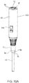
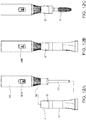
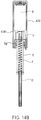
- Figures 9A-C demonstrate the use of the applicator as so far described.
- Figures 7A-C demonstrate the same use, only in cross section.
- Figures 7A and 9A depict a first subassembly and a second subassembly prior to joining.
- the rotating collar (6) is in the off position, and the sleeve (10a) is covering the heat generating portion.
- an advantage of the sliding sleeve mechanism may be realized. If the heating circuit is turned on while the sleeve (10a) is covering the heat generating portion, then heat generating portion will heat up faster because the heat is trapped within the sleeve, very close to the heat generating portion.
- Figures 7B and 9B show the second subassembly inserted into the first subassembly.
- the rotating collar is still shown in the off position, in intended use a user will usually want to turn the rotating collar to the on position while the heat generating portion is disposed in the product reservoir (1), if she has not already done so.
- the lugs (5d) are engaged in their respective locking grooves (2f)
- the first and second subassemblies are fixedly joined.
- neck extension (2) and applicator head (3) can be removed from the reservoir (1) by an unscrewing motion applied to the handle (4).
- Figures 7C and 9C shows the applicator head out of the reservoir, and the rotating collar (6) is shown in the on position.
- the heat generating portion inside the applicator head is heating up and heating the product on the working surface (3a) of the applicator head.
- the user When a user is done applying the product, she may turn off the heating circuit, return the applicator head (3) to the reservoir (1), and tightly seal the reservoir to preserve the contents of the reservoir between uses. Eventually, when the contents of the reservoir are exhausted, the user can disengage the lug(s) (5d) from the locking groove(s) (2f), and the second subassembly is recovered.
- the first subassembly which preferably does not comprise any electrical components, may be discarded, and the second subassembly may be reused with a new first subassembly.
- FIGs 10-13 shows a second embodiment of the second subassembly (SS2).
- the on-off switch of the heating circuit is a sliding switch (60b) having a switch cover (60a).
- the sliding switch is mounted directly into the printed circuit board (7), such that the sliding switch is able to open and close the heating circuit.
- the positive terminal of the battery maintains physical contact with the printed circuit board at PCB terminal (T1).
- the rotating collar (6), and tabs (9) are no longer needed.
- the switch cover (60a) slides in switch slot (40m) and a portion of the switch cover passes through handle (40) to connect to switch (60b).
- FIG. 11 shows one embodiment of a contact between the first metallic lead (4d) and second terminal (T2) of the printed circuit board.
- the end of the first metallic lead is formed as three prongs (40k) that sandwich the second terminal on three sides.
- the heating circuit housing (50) is similar to, but differs somewhat from that described above.
- the housing still has an upper end (50a) situated inside the handle (40) such that the housing does not move substantially in relation to the handle.
- the housing still has one or more vertical extensions (50f) rise above the upper end. Three such extensions are shown in figures 10b and 11 , which are designed to help secure the enlarged portion (7a) of the printed circuit board (7).
- the upper end of the housing may not require a vertical groove to accommodate tabs (9), since the tabs have been eliminated.
- the upper end of the heating circuit housing does not have threads on an interior surface, since the rotating collar has been eliminated.
- the absence of the rotating collar allows a tapered transition (or any other shape or aesthetic feature) to be implemented between the upper and lower ends of the circuit housing.
- Another feature of some embodiments of the heated circuit housing (50) is the presence of one or more locking tabs (50h) arising from the top (50a) of the housing. These tabs are designed to catch in mated slots (7h) on the enlarged portion of the printed circuit board, to help securely hold the printed circuit board in relation to the heating circuit housing.
- the lower end (50b) of the heating circuit housing is able to form a rigid connection to the neck extension (2), thus joining the first and second subassemblies.
- the connection between subassemblies is detachable so that the second subassembly can be reused with a different first subassembly.
- Various connection means were discussed above, such as a lug-style fitment.
- two lugs (5d) are provided, each of which is accommodated in its own transit groove (2e) and locking groove (2f) in the neck extension (2).
- Figures 14A-C show a third embodiment of the second subassembly (SS3).
- a spring (4e) serves a dual purpose.
- a first purpose of the spring is to serve as an electrical lead to the negative terminal of the battery (8).
- a second purpose is to urge the battery from a first position to a second position. In the first position, when the spring is more compressed against the handle (400), the battery's positive terminal is not making electrical contact with the printed circuit board. In this arrangement, current cannot flow to the heat generating portion (7c).
- the battery's positive terminal is making electrical contact with the printed circuit board, in a way that allows current to flow to the heat generating portion.
- the enlarged portion (7a) of the printed circuit board comprises an electric lead (T1) that is able to contact a positive terminal of the battery, when the battery is in its second position.
- the heating circuit comprises battery (8), electric lead T1, the circuitry of the printed circuit board (7), electric leads (T2), (4d), (4c) and spring (4e).
- the recharging circuit differs from the first and second embodiments in the position of recharging leads. In this case, the recharging circuit is accessible near the bottom (4b) of the handle (400).
- negative recharging lead (400f) depends downwardly from lead (4d), which leads back to the negative terminal of the battery (8).
- Positive recharging lead (400h) is welded to and depends downwardly from the positive terminal of the battery. Both recharging leads wrap around the bottom edge of the handle, and may continue up the outside of the handle for a short distance.
- slots (400p, 400q) may be provided in the outside of the handle. Because one end of the positive recharging lead is welded to the battery, this lead is sufficiently flexible to accommodate the movement o the battery. The purpose of this will be seen below.
- the heating circuit housing (5) is like that of the first embodiment of the second subassembly.
- the housing still has an upper end (5a) situated inside the handle (400) such that the housing does not move substantially in relation to the handle.
- the housing has one or more vertical extensions (5f) that rise above the upper end (5a) of the housing, which has at least one vertical groove (5e) to accommodate a tab (9).
- the upper end of the heating circuit housing has threads (5g) on an interior surface, but these are not for attaching to a rotating collar switch, which is not present in this embodiment. In this case, the on-off switch of the heating circuit is engaged when the second subassembly is mounted and demounted from a base, as described below.
- the lower end (5b) of the heating circuit housing is able to form a rigid connection to a neck extension (2), thus joining the first and second subassemblies.
- a detachable lug-style fitment may be preferred.
- Automatic switching means that the heating circuit and/or recharging circuit are turned on or off as a result of normal use of the applicator.
- the applicator is used in conjunction with a base, which may be a recharging base or simply a convenience stand for storing the applicator when not in use.
- a base which may be a recharging base or simply a convenience stand for storing the applicator when not in use.
- one or more tabs (9) are provided, as shown in figure 14B . A lower end of the tab is able to extend below the bottom (4b) of the handle (400) and an upper end is able to contact the battery (8).
- the tab passes from outside the handle to the inside of the handle through a vertical groove (5e) in the heating circuit housing.
- the tab contacts a surface of the base. As a result the tab moves further into the handle. When this happens, contact between the tab and the battery forces the battery further up the handle, away from contact with the printed circuit board (7), and compressing the spring (4e). Thus, the electric heating circuit is opened, and no current flows to the heat generating portion (7c). However, the flexible positive recharging lead (400h) maintains contact with the positive terminal of the battery, so that a recharging circuit may be completed. When the threads (5g) are not engaged, then the tabs are free to move further out of the handle.
- the spring expands, forcing the battery toward the printed circuit board, until a positive terminal of the battery contacts electrical lead (T1) of the printed circuit board.
- the electric heating circuit is closed, and current flows to the heat generating portion.
- the heating circuit is turned on and off by virtue of removing the applicator from or returning the applicator to a base.
- Various parameters of the heated applicators described herein will affect the amount of heat required to raise the temperature of a product in the reservoir (1) and/or the amount of time required to do it. For example, in general the more product in the reservoir, the more heat will be needed to raise the temperature of the product to a product application temperature, in a given amount of time. Also, for example, given a specific rate of heat generation, a thicker applicator head (3) means more time will be needed to raise the temperature of the product in the reservoir. To increase the rate of heat transfer through the applicator head, and to reduce the amount of heat lost, it may be preferable to make the hollow stem (3b) of applicator head as thin as possible, considering the limitations of manufacture in the specific material used.
- the thickness of the wall of the applicator head is less than 1.0mm, more preferably less than 0.8mm, even more preferably less than 0.6mm and most preferably less than 0.4mm.
- the amount of heat and/or the length of time needed to raise the temperature of a product disposed in the reservoir also depends on the thermal conductivity of the material(s). So, in general, to decrease the amount of time required to raise the temperature of the product, one might increase the rate of heat generation, decrease the mass being in heated (thinner applicator head), and/or increase the thermal conductivity of the applicator head.
- Heated applicators according to the present invention are configured to raise the temperature of a dose of product from an ambient temperature to a product application temperature. That temperature may be adjusted to market demands.
- the product application temperature may be30°C or greater, or 40°C or greater, or 50°C or greater, or 60°C or greater, and so on, as the situation dictates.
- an applicator herein described is able to heat an amount of product from an ambient temperature to a product application temperature, in 60 seconds or less, preferably 30 seconds or less, more preferably 15 seconds or less, and most preferably 5 seconds or less. As a result of heating, some characteristic of the dispensed product is enhanced or improved.
- the enhanced or improved characteristic may be for example a reduction in viscosity, activation of an active ingredient, a threading effect in a mascara product, a longer shelf life, a feeling of warmth experienced by the consumer, enhanced penetration of the product into the skin of a user, release of an encapsulated ingredient, or any other change that benefits the user.
- the second subassembly may comprise a rechargeable power source.
- the exterior of the handle (4) is provided with recharging leads that allow the rechargeable power source in the handle to be connected to an external power reservoir.
- Some embodiments of the present invention comprise a recharging means.
- a recharging means is able to effect electrical contact between the recharging leads of the second subassembly and the external power reservoir. Once the electrical contact is made, electrical power is able to be transmitted from the external power source, to the rechargeable power source for storage.
- One embodiment of a recharging means is a current/voltage regulating cord.
- the recharging means takes the form of a docking station or recharging base.
- a recharging base will have one or more ports for receiving a second subassembly. The port is such that when a second subassembly is disposed therein, electrical contact is established between the recharging leads of the second subassembly and the external power reservoir.
- the external power reservoir may reside in the recharging base, or the recharging base itself has to be plugged into an external power source.
- a recharging base may have exactly one port, since the present invention requires only one second subassembly. However, more ports may be provided to accommodate any number of second subassemblies.
- the battery (8) may be recharged while the neck extension (2) and applicator head (3) are attached to the second subassembly. However, due to the short operational lifetime of the neck extension and applicator head, these components may be disposed before recharging.
- Figure 13 shows one embodiment of a recharging base (15) that is suitable for those embodiments where the recharging leads (4f, 4g) are accessible near the top (4a) of the handle (40).
- the recharging base may have various indicator lights.
- indicator light (15a) is able to signify that power source (8) is being charged
- indicator light (15b) is able to signify that the power source is fully charged or sufficiently charged for intended use.
- a power cord (15c) enables the recharging base to be plugged into a household-type current source.
- the recharging base comprises any electrical componentry needed to regulate and/or modulate the source current coming from through the power cord.
- the second subassembly is shown in a port (15d) of the recharging base without a first subassembly attached.
- the handle (40) and recharging base (15) may optionally be provided with a means of registering the recharging leads (4f, 4g) of the handle with the appropriate leads of the recharging base.
- the recharging base is provided with a detent (15n) that cooperates with a groove (40n) of the handle, so that the handle can only be inserted in the recharging port (15d) in a configuration that is effective to recharge the power source (8).
- Figures 15 and 16 show one embodiment of a recharging base (150) that is suitable for those embodiments where the recharging leads (4f, 4h) are accessible near the bottom (4b) of the handle (400).
- the embodiments covered by figure 14A are examples of this type.
- the base comprises a power reservoir or a means to connect to a power reservoir.
- the power reservoir may be municipal source that can be accessed via an electrical outlet and power cord.
- the recharging base comprises any electrical componentry needed to regulate and/or modulate the source current coming through the power cord.
- the recharging base may be provided with self contained power reservoir (150e), which may itself be rechargeable. In this case, the recharging base would be more fully portable than if it always had to be connected to an external power reservoir.
- the base has at least one recharging port (150d).
- the base has more than one port, so that more than one second subassembly can be recharged simultaneously.
- the base has at least three recharging ports.
- the recharging base (150) may be more suitable for in-store counter use, where several second subassembly may be needed at one time, as opposed to home use.
- Each port is comprised of a threaded collar (150g) into which the printed circuit board (7) is disposed. The threaded collar is mated to engage the threads (5g) of the heated circuit housing.
- the recharging leads (400f, 400h) of the handle(400) register with negative (150f) and positive (150h) electrical contacts of the collar. These electrical contacts are electrically connected to the power reservoir (150e) by any suitable circuitry, such as conductors (150i, 150j) that conduct electricity to and from negative (150m) and positive (150n) terminals of the power reservoir.
- any suitable circuitry such as conductors (150i, 150j) that conduct electricity to and from negative (150m) and positive (150n) terminals of the power reservoir.
- the recharging circuit is opened, but at the same time the electric heating circuit is closed, and current flows to the heat generating portion.
- the heating and recharging circuits are in opposite states (on or off). For example, when in the base, the recharging circuit is necessarily closed and the heating circuit is necessarily opened. When out of the base, the recharging circuit is necessarily opened and the heating circuit is necessarily closed.
- a container (150p) depends from each port (150d), down into the base.
- the container provides a secure and sanitary location for the printed circuit board while the second subassembly is in the recharging base.
- the recharging base may have various indicator lights as mentioned above.
- the power reservoir is able to simultaneously recharge as many second subassemblies as there are ports (150d).
- the power reservoir is able to recharge at least three second subassemblies before itself needing to be recharged; more preferably at least 5 second subassemblies; even more preferably at least 10second subassemblies before needing to be recharged.
- the heating elements may be automatically switched on and off (i.e. activated and deactivated). "Automatically switched” means that the heating elements are turned on or off as a result of normal use of the applicator. For example, when the PCB housing (5 or 50) is being attached to the neck extension (2), the heating generating portion (7c) may be activated, and then deactivated as the PCB housing is being detached from the neck extension. The advantage here is that the there is no chance that the heating generating portion will be left on when it is not inserted in an applicator head.
- a first on-off mechanism could be a manual on-off mechanism, such as described above, and a second on-off mechanism could be an automatic switch. These could be wired to operate as a so-called "three-way" switch, giving a user the option of over-riding the automatic switch.
- the present invention is configured to raise the temperature of a dose of product from an ambient temperature to a product application temperature in a defined amount of time. Since the consumer may have to wait for heating to occur, the dispenser may be provided with an indication that the product has reached application temperature, and application can begin.
- a portion of the exterior surface of the reservoir (1) may be fashioned from a material that reacts to changes in temperature, i.e. by changing color.
- the "thermochromic" surface should be sufficiently close to the heat generating portion so that a visible color change occurs within a several seconds of the product in the chamber reaching application temperature; i.e. no more than 10 seconds, preferably, no more than 5 seconds, more preferably no more than 3 seconds.
- the electric circuit may include an LED that lights up when the product in the reservoir has reached an application temperature. The system may also have an LED that lights up as soon as the heating circuit is closed, to tell a user that the heating circuit is on.
- the second subassembly may comprise electric circuits other than the heating circuit. These may offer a user other functionality or convenience.
- electric circuits may be provided for a vibration system, a lighting system, a sound system, one or more logic circuits, one or more memory circuits, one or more communications circuits, one or more signal transmission systems, one or more signal processing systems, etc.
- a non-exhaustive list of product types that may benefit from being supplied in an applicator system according to the present invention includes: products heated for aesthetic reasons (i.e. shave cream); those heated to activate an ingredient; those heated to alter the rheology of the product; those heated to sterilize the product; those heated to release an encapsulated ingredient, as by melting a gelatin capsule, for example.
- Particularly preferred products are eyelash products, such as mascara.
- Forms of product include creams, lotions, serums, gels, liquids, pastes, powders or any product that may be applied with a handheld applicator of the types known to be used in the cosmetic and personal care fields.
- the reservoir (1) of the system is designed to hold a finished product.
- a "finished product” is one that could be used even without heating, or one that requires only heating prior to use. Therefore, products that require additional preparation beyond heating, may not be suitable or may be less suitable for the present invention.
- a pre-shave foam mixture that must be combined with a liquid propellant outside of the reservoir (1), would not be suitable for use in the present invention.
- An exception to this includes products that can be constituted by shaking the reservoir prior to use.
- the products may be mixtures, suspensions, emulsions, dispersions or colloids.
- Particularly preferred products are those that could be exploited by having some structural or dynamic property temporarily altered by heating. For example, heating may temporarily reduce the viscosity of a mascara product to improve application and make application easier, whereas, after cooling, the viscosity of the mascara may return to near pre-heating levels.
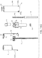
- the first and second subassemblies Prior to any use, are physically separated, as shown in figure 12A .
- steps whose order may vary. include, inserting the heat generating portion (7c) into the hollow interior of the applicator head (3), turning on the heating circuit, separating the neck extension (2) from the reservoir (1), and raising the applicator head out of the reservoir.
- the steps of inserting the heat generating portion and turning on the heating circuit may be performed in either order.
- the steps of separating the neck extension from the reservoir and turning on the heating circuit may be performed in either order.
- the steps of raising the applicator head out of the reservoir and turning on the heating circuit may be performed in either order.
- the applicator head is rigidly associated with the second subassembly.
- the applicator head (3) can be used to transfer heated product to an intended surface, such as hair or skin. Thereafter, the applicator head may be returned to the reservoir to retrieve more product or to store the applicator head for a later use. After the applicator has been used, the heating circuit can be turned off.
- Additional method steps may include reconnecting the neck extension and reservoir and/or reinserting the applicator head (3) into the reservoir (1). Also, at whatever point the heating circuit is turned on, the user may wait a recommended amount of time for the product on the applicator head to heat up, and for some characteristic of the product to be improved or enhanced. In general, the actual amount of time for the product to heat will depend on the method used. For example, a longer amount of time may be required when the heating circuit is engaged after the applicator head is out of the reservoir. A shorter amount of time may be required when the heat generating portion is heating as it sits in the reservoir. The tight confines of the reservoir should improve heating efficiency compared to heating the applicator head outside of the reservoir.
- the heating circuit housing (50) may be separated from the neck extension (2) (for example, by disengaging the lug-style fitment), and the heat generating portion (7c) can be removed from the interior of the applicator head (3).
- the second subassembly has been recovered, and may be reused with another first subassembly.
- the exhausted reservoir (1), neck extension (2) and used applicator head (3) are disposed.
- the step of waiting a period of time may include the user waiting at least as long as directed by someone or something other than the user.
- the waiting period may be less than 60 seconds, preferably 30 seconds or less, more preferably 15 seconds or less, even more preferably 10 seconds or less.
- the user may wait until a thermochromic material has visibly changed color.
- the present invention eliminates or substantially reduces the occurrence of product degradation, such as dry out of mascara, in the reservoir and on the applicator head.
- product degradation such as dry out of mascara
Landscapes
- Brushes (AREA)
- Coating Apparatus (AREA)
- Thermotherapy And Cooling Therapy Devices (AREA)
- Sampling And Sample Adjustment (AREA)
Claims (26)
- Ein Wärmeapplikator-System, das Folgendes umfasst:einen ersten Einwegunteraufbau, der Folgendes umfasst:ein Reservoir (1) mit einem oberen Ende (1a) in der Form eines hohlen Halses, wobei der Hals eine obere Öffnung (1c) aufweist, die Zugang zum Innenraum des Reservoirs (1) verschafft;eine Verlängerung (2) des hohlen Halses, die mit dem Hals des Reservoirs (1) in lösbarer und wiederanbringbarer Weise verbunden ist, so dass die obere Öffnung (1c) des Reservoirs (1) von der Halsverlängerung (2) umgeben ist; undeinen Applikatorkopf (3), der von der Halsverlängerung (2) herabhängt und durch die obere Öffnung (1c) hindurch in das Reservoir (1) erlangt, wobei der Applikatorkopf (3) Folgendes umfasst:einen hohlen Schaft (3b), der einen geöffneten proximalen Abschnitt (3c) und einen geschlossenen distalen Abschnitt (3d) aufweist, wobei der geschlossene distale Abschnitt (3d) eine Arbeitsfläche (3a) stützt;so dass, wenn das Reservoir (1), die Halsverlängerung (2) und der Applikatorkopf (3) zusammengebaut sind, das Innere des Reservoirs (1) von der Raumumgebung abgedichtet ist und die Arbeitsfläche (3a) des Applikatorkopfs (3) in das Reservoir (1) eingetaucht ist; und dass ein Durchgang durch die Halsverlängerung (2) und in den geschlossenen distalen Abschnitt (3d) des Applikatorkopfs (3) hinein vorhanden ist; undeinen zweiten wiederverwendbaren Unteraufbau, der Folgendes umfasst:einen hohlen Griff (4) mit einem proximalen Ende (4a) und einem geöffneten distalen Ende (4b);eine in dem Griff (4) angeordnete Stromquelle (8);ein hohles Gehäuse (5) für den elektrischen Heizschaltkreis, welches ein oberes Ende (5a) und ein unteres Ende (5b) aufweist, wobei das obere Ende (5a) des Gehäuses (5) an dem Griff (4) befestigt ist und das untere Ende (5b) des Gehäuses (5) in der Lage ist, eine steife, lösbare Verbindung mit der Halsverlängerung (2) zu bilden; undeinen elektrischen Heizschaltkreis (7), der so durch das Gehäuse (5) des elektrischen Schaltkreises verläuft, dass ein wärmeerzeugender Abschnitt (7c) des Heizschaltkreises (7) aus dem unteren Ende (5b) des Gehäuses (5) herausragt;wobei, wenn das Gehäuse (5) für den elektrischen Schaltkreis dazu veranlasst wird eine steife Verbindung mit der Halsverlängerung (2) zu bilden, der wärmeerzeugende Abschnitt innerhalb des Applikatorkopfs (3) angeordnet ist;dadurch gekennzeichnet, dass das Wärmeapplikator-System, ferner eine Gleithülse (10a) umfasst, die den wärmeerzeugenden Abschnitt bedeckt, wenn der erste und zweite Unteraufbau nicht angebracht sind, und diese in das Gehäuse (5) für den Heizschaltkreis eingezogen wird, wenn der wärmeerzeugende Abschnitt (7c) in den Applikatorkopf (3) eingeführt wird.
- Das System nach Anspruch 1, das ferner ein Wischerelement umfasst, das als ein konisch geformter, nach unten gebogener Abschnitt (1e) gebildet ist, der von dem unteren Ende des Halses herabhängt.
- Das System nach Anspruch 1, wobei die Halsverlängerung (2) durch zusammenwirkende Gewinde mit dem Hals des Reservoirs (1) verbunden ist.
- Das System nach Anspruch 1, wobei der elektrische Heizschaltkreis (7) eine Leiterplatte umfasst und der wärmeerzeugende Abschnitt (7c) eine Vielzahl einzelner, getrennter Widerstandsheizelemente umfasst, die auf einem unteren Abschnitt der Leiterplatte außerhalb des Gehäuses (5) des elektrischen Schaltkreises gestützt werden.
- Das System nach Anspruch 4, wobei die Leiterplatte ein Substrat umfasst, das nicht elektrisch leitfähig ist und das elektronische Bauteile und elektrische Leitungen stützt, die es bewirken, den wärmeerzeugenden Abschnitt (7c) mit der Stromquelle (8) zu verbinden.
- Das System nach Anspruch 5, das den wärmeerzeugenden Abschnitt (7c) etwa 2 bis 5 Minuten nachdem der wärmeerzeugende Abschnitt (7c) eine vorgegebene Temperatur erreicht hat, automatisch abschaltet.
- Das System nach Anspruch 6, das einen Spannungsteilerschaltung und einen Thermistor umfasst.
- Das System nach Anspruch 7, das ferner einen Operationsverstärker und einen N-Kanal-MOSFET-Schalter umfasst.
- Das System nach Anspruch 4, wobei es sich bei den Heizelementen um eine Bank von Festwertwiderständen handelt, die elektronisch in Reihe, parallel oder in jeglicher Kombination davon angeordnet und physisch in zwei Reihen angebracht sind, eine auf jeder Seite der Leiterplatte.
- Das System nach Anspruch 9, wobei die Festwertwiderstände Nennwiderstände von 1 bis 10 Ohm aufweisen.
- Das System nach Anspruch 10, wobei der Gesamtwiderstand aller Heizelemente im Bereich von 1 bis 10 Ohm liegt.
- Das System nach Anspruch 11, wobei es sich bei den Widerstandsheizelementen um Metalloxid-Dickfilm, Chipwiderstände handelt, wovon das größte Ausmaß 2,0 mm oder weniger beträgt.
- Das System nach Anspruch 11, wobei die Widerstandsheizelemente getrennte Punkte eines Metalloxid-Dickfilms sind, der als Siebdruckschicht auf der Leiterplatte bereitgestellt ist.
- Das System nach Anspruch 13, wobei der Metalloxid-Dickfilm aus Rutheniumoxid (RuO2) besteht und jeder Punkt 2,0 mm oder weniger beträgt.
- Das System nach Anspruch 4, wobei die Widerstandsheizelemente in einer kontinuierlichen festen Masse eines Wärmeübertragungsmaterials eingebettet sind.
- Das System nach Anspruch 15, wobei es sich bei dem Wärmeübertragungsmaterial um einen oder mehrere thermisch leitfähige Klebstoffe, einen oder mehreren thermisch leitfähige Einkapselungsepoxide oder eine Kombination derselben handelt.
- Das System nach Anspruch 1, wobei die steife lösbare Verbindung des Gehäuses (5) des Heizkreislaufs mit der Halsverlängerung (2) als ein laschenartiger Verriegelungsmechanismus ausgeführt ist, wobei:die Halsverlängerung (2) mindestens eine Durchgangsnut (2e) und mindestens eine Verriegelungsnut (2f) umfasst, die sich in einem ungefähr rechten Winkel zur Durchgangsnut (2e) erstreckt; unddas Schaltkreisgehäuse (5) mindestens eine zusammenwirkende Lasche (5d) umfasst, die sich abwärts entlang der Durchgangsnut (2e) bewegen und in die Verriegelungsnut (2f) eindringen kann.
- Das System nach Anspruch 1, wobei der Zugang zur Stromquelle (8) durch einen entfernbaren Deckel in dem proximalen Ende (4a) des Griffs (4) erfolgt.
- Das System nach Anspruch 1, das ferner positive und negative Wiederaufladeleitungen (4f, 4g) auf der Außenseite des Griffs (4) umfasst, die elektrisch mit einem externen Energiespeicher (150e) verbunden werden können, so dass, wenn der externe Energiespeicher (150e) angeschlossen ist, ein Wiederaufladeschaltkreis abgeschlossen wird, der es bewirkt, dass Strom von dem externen Energiespeicher (150e) zur Speicherung zu der Stromquelle (8) übertragen wird.
- Das System nach Anspruch 19, wobei sich die Wiederaufladeleitungen (4f, 4g) um die Unterkante des Griffs (4) wickeln.
- Das System nach Anspruch 19, das ferner eine Wiederaufladebasis (150) umfasst, die einen oder mehrere Ports (150d) aufweist, die den zweiten Unteraufbau aufnehmen können, so dass, wenn der zweite Unteraufbau darin angeordnet ist, elektrischer Kontakt zwischen den Wiederaufladeleitungen (4f, 4g) des zweiten Unteraufbaus und dem externen Energiespeicher (150e) hergestellt wird.
- Das System nach Anspruch 19, wobei der externe Energiespeicher in der Wiederaufladebasis (150) untergebracht ist und die Wiederaufladebasis mindestens drei Ports (150d) aufweist, wobei jeder Port aus Folgendem besteht:einem, mit einem Gewinde versehenen Kragen (150g), in dem die Leiterplatte angeordnet ist; undeinem Behälter (150p), der von jedem Port bis hinunter in die Wiederaufladebasis herabhängt.
- Das System nach Anspruch 1, das ferner einen An-Aus-Mechanismus umfasst, der mindestens zwei Stellungen hat, wobei der Mechanismus in mindestens einer der Stellungen elektrischen Kontakt zwischen dem wärmeerzeugenden Abschnitt (7c) und der Stromquelle (8) herstellt, und der Mechanismus in mindestens einer der Stellungen den elektrischen Kontakt zwischen dem wärmeerzeugenden Abschnitt (7c) und der Stromquelle (8) unterbricht, wobei der Mechanismus von der Außenseite des Spenders zugänglich ist und von einem Benutzer entweder direkt oder indirekt eingerastet werden kann.
- Ein erster Einwegunteraufbau nach Anspruch 1, wobei das Reservoir (1) ein Produkt (P) enthält, das weniger als 10% Wasser umfasst.
- Ein Verfahren zum Verwenden eines Wärmeapplikator-Systems, das folgende Schritte umfasst:Bereitstellung eines Wärmeapplikator-Systems, nach Anspruch 1, wobei der erste und der zweite Unteraufbau anfänglich physisch voneinander getrennt sind und wobei das Reservoir (1) genügend Produkt für 1 bis 14 Anwendungen enthält;Einführung des wärmeerzeugenden Abschnitts (7c) in das hohle Innere des Applikatorkopfs (3);Verbindung des Gehäuses (5) für den Heizschaltkreis mit der Halsverlängerung (2);Einschaltung des elektrischen Heizschaltkreises (7);Trennung der Halsverlängerung (2) von dem Reservoir (1);Herausziehen des Applikatorkopfs (3) aus dem Reservoir (1).
- Das Verfahren nach Anspruch 25, das ferner einen oder mehrere der folgenden Schritte umfasst:Übertragung eines erhitzten Produkts (P) auf die Haare oder die Haut;Wiedereinführung des Applikatorkopfs (3) in das Reservoir (1);Ausschaltung des Heizschaltkreises (7);Trennung des Gehäuses (5) für den Heizschaltkreis von der Halsverlängerung (2);Entfernung des wärmeerzeugenden Abschnitts (7c) aus dem Inneren des Applikatorkopfs (3);erneute Verbindung der Halsverlängerung (2) und des- Reservoirs (1);Entsorgung des Reservoirs (1), des Applikatorkopfs (3) und der Halsverlängerung (2); und/oderWiederverwendung des zweiten Unteraufbaus mit einem anderen ersten Unteraufbau.
Applications Claiming Priority (2)
| Application Number | Priority Date | Filing Date | Title |
|---|---|---|---|
| US12/980,526 US8585307B2 (en) | 2010-12-29 | 2010-12-29 | System for sampling a heated product |
| PCT/US2011/066229 WO2012092032A2 (en) | 2010-12-29 | 2011-12-20 | Heating applicator system for products that may be degraded by heat |
Publications (3)
| Publication Number | Publication Date |
|---|---|
| EP2658413A2 EP2658413A2 (de) | 2013-11-06 |
| EP2658413A4 EP2658413A4 (de) | 2015-05-20 |
| EP2658413B1 true EP2658413B1 (de) | 2017-04-19 |
Family
ID=46380883
Family Applications (2)
| Application Number | Title | Priority Date | Filing Date |
|---|---|---|---|
| EP11852806.6A Active EP2658414B1 (de) | 2010-12-29 | 2011-12-20 | System zur probenentnahme aus einem erwärmten produkt |
| EP11852384.4A Active EP2658413B1 (de) | 2010-12-29 | 2011-12-20 | Erwärmungsapplikatorsystem für durch wärme zersetzungsfähige produkte |
Family Applications Before (1)
| Application Number | Title | Priority Date | Filing Date |
|---|---|---|---|
| EP11852806.6A Active EP2658414B1 (de) | 2010-12-29 | 2011-12-20 | System zur probenentnahme aus einem erwärmten produkt |
Country Status (9)
| Country | Link |
|---|---|
| US (1) | US8585307B2 (de) |
| EP (2) | EP2658414B1 (de) |
| JP (1) | JP5891245B2 (de) |
| KR (1) | KR101427059B1 (de) |
| CN (1) | CN103338676B (de) |
| AU (1) | AU2011352863B2 (de) |
| CA (1) | CA2824601C (de) |
| ES (2) | ES2632789T3 (de) |
| WO (1) | WO2012092024A2 (de) |
Families Citing this family (16)
| Publication number | Priority date | Publication date | Assignee | Title |
|---|---|---|---|---|
| US8950962B2 (en) * | 2010-12-29 | 2015-02-10 | Elc Management, Llc | Heating applicator system for products that may be degraded by heat |
| DE202012102938U1 (de) * | 2012-08-03 | 2013-11-06 | Geka Gmbh | Applikatoreinheit zum Auftragen eines Kosmetikums |
| US10278470B2 (en) * | 2012-10-04 | 2019-05-07 | Shiseido Co., Ltd. | Cosmetic tool |
| FR2999886B1 (fr) * | 2012-12-26 | 2015-03-20 | Lvmh Rech | Dispositif applicateur et systeme de conditionnement et d'application de produit cosmetique, et leur utilisation |
| DE202013006927U1 (de) * | 2013-08-02 | 2014-11-03 | Geka Gmbh | Einstückiger Applikator mit Fensterkappe |
| US9320337B2 (en) * | 2014-06-19 | 2016-04-26 | Elc Management, Llc | Heated cosmetic sampler with incorporated applicator |
| FR3035576B1 (fr) * | 2015-04-29 | 2018-11-23 | L'oreal | Support chauffant pour un applicateur de produit cosmetique avec element chauffant |
| WO2017004673A1 (en) * | 2015-07-06 | 2017-01-12 | Mitchell Terrace Pty. Ltd. | Device for applying a product |
| KR20170024239A (ko) * | 2015-08-25 | 2017-03-07 | 주식회사 디엠코스메틱스 | 도어기능을 갖는 마스카라 용기 |
| US9781991B1 (en) * | 2016-03-16 | 2017-10-10 | Elc Management Llc | Heating applicator system with reusable components |
| KR101750832B1 (ko) * | 2016-07-28 | 2017-06-27 | 주식회사 디엠코스메틱스 | 화장용 항균 퍼프 |
| US20220378173A1 (en) * | 2017-03-29 | 2022-12-01 | Lg Household & Health Care Ltd. | Mascara |
| KR102201522B1 (ko) * | 2017-12-18 | 2021-01-12 | (주)아모레퍼시픽 | 팁 어플리케이터 및 이를 포함하는 화장료 도포장치 |
| US20210046277A1 (en) * | 2018-02-02 | 2021-02-18 | Microbot Medical Ltd. | Self-cleaning catheter systems |
| US11358167B2 (en) | 2020-01-22 | 2022-06-14 | Elc Management Llc | Reusable pump dispenser |
| US12372443B2 (en) | 2021-01-07 | 2025-07-29 | Fremonta Corporation | Devices, systems and methods for microbial sampling of frozen products |
Family Cites Families (58)
| Publication number | Priority date | Publication date | Assignee | Title |
|---|---|---|---|---|
| US2488591A (en) | 1947-01-07 | 1949-11-22 | Fevas Anna | Electrically heated applicator |
| US3518410A (en) | 1967-03-01 | 1970-06-30 | Colgate Palmolive Co | Electrical heating device for fluent products |
| US4067480A (en) | 1972-03-10 | 1978-01-10 | Colgate-Palmolive Company | Process for dispensing pressurized fluent material |
| US4291685A (en) | 1979-06-15 | 1981-09-29 | Taelman Dennis L | Therapeutic heat and cosmetic applicator |
| FR2460644A1 (fr) | 1979-07-10 | 1981-01-30 | Seb Sa | Pulverisateur de vapeur d'eau, a usage domestique, pour les soins de la peau |
| US4329567A (en) | 1979-08-27 | 1982-05-11 | Clairol Incorporated | Electrically heated rotatable curler brush |
| FR2495906A1 (fr) | 1980-12-12 | 1982-06-18 | Seb Sa | Appareil pour epiler a la cire, notamment pour le visage |
| JPS59101911U (ja) * | 1982-12-27 | 1984-07-09 | ビツグウエイ株式会社 | 液状化粧料カ−トリツジ容器 |
| US4538630A (en) | 1983-03-10 | 1985-09-03 | Henderson Gordon W | Microwave heated hair curler |
| GB8510926D0 (en) | 1985-04-30 | 1985-06-05 | Pifco Ltd | Hair treatment device |
| US4733784A (en) | 1986-11-17 | 1988-03-29 | R.J.S. Industries, Inc. | Container and applicator for fluids |
| JPH038199Y2 (de) * | 1987-03-19 | 1991-02-28 | ||
| US4889440A (en) | 1987-08-31 | 1989-12-26 | Lectro Stik Corp. | Wax applicator with electronic control |
| FR2633498B1 (fr) | 1988-06-30 | 1992-03-06 | Oreal | Ensemble applicateur destine au maquillage des cils comportant un pain de mascara et un element de distribution humidifie |
| FR2640479B1 (fr) * | 1988-12-20 | 1991-03-22 | Oreal | Ensemble applicateur destine notamment au maquillage des cils, comportant un element applicateur fixe sur une tige |
| FR2696659B1 (fr) | 1992-10-09 | 1994-12-16 | Seb Sa | Applicateur de produits thermofusibles, en particulier de cire à épiler, à réservoir chauffant. |
| FR2706261B1 (fr) | 1993-06-14 | 1995-09-01 | Seb Sa | Applicateur de produits thermofusibles, en particulier de cire à épiler, comportant un rouleau d'application bi-matière. |
| FR2724095B1 (fr) * | 1994-09-05 | 1996-10-31 | Oreal | Dispositif de conditionnement et d'application de produit de maquillage |
| CA2131937C (en) | 1994-09-13 | 1999-04-06 | Gerald Cote | Shaving dispenser |
| US6009884A (en) | 1996-01-31 | 2000-01-04 | Suh; Jeong Joo | Eyelash curler |
| US5775344A (en) | 1996-02-09 | 1998-07-07 | Clay; Mary A. | Cosmetic container and applicator with heating apparatus |
| CA2206690C (en) | 1996-06-18 | 2005-02-08 | Michael Victor Vecchiola | Temperature indicating hair brush |
| US5851079A (en) | 1996-10-25 | 1998-12-22 | The Procter & Gamble Company | Simplified undirectional twist-up dispensing device with incremental dosing |
| KR100217490B1 (ko) | 1996-12-18 | 1999-09-01 | 서정주 | 속눈썹 성형구 |
| DE19839940A1 (de) | 1998-09-02 | 2000-03-09 | Stern Hans Jakob | Haarbearbeitungsgerät |
| US6454127B1 (en) | 2000-08-17 | 2002-09-24 | Sheree Suomela | Self-contained liquid dispenser with heating means |
| US6508603B1 (en) | 2000-11-17 | 2003-01-21 | The Bridgeport Metal Goods Manufacturing Company | Mascara brush configured for loading from sidewall of container |
| KR200230093Y1 (ko) | 2000-12-01 | 2001-07-04 | 김지수 | 바이브레이팅 립스틱 |
| US6911010B2 (en) | 2001-12-21 | 2005-06-28 | Wahl Clipper Corporation | Heated massager with massaging liquid dispenser |
| US7086861B2 (en) | 2002-03-01 | 2006-08-08 | Pitz Richard J | System for dispensing viscous materials |
| JP4343172B2 (ja) | 2002-12-13 | 2009-10-14 | ロレアル | メイクアップの方法及びスキンケア製品を塗布する方法、並びにそのような方法の実施に用いる器具 |
| FR2849753B1 (fr) | 2003-01-13 | 2006-08-18 | Oreal | Procede de chauffage d'un support sur lequel ou a l'interieur duquel est dispose un produit cosmetique |
| FR2852795B1 (fr) | 2003-03-24 | 2005-05-06 | Oreal | Ensemble de conditionnement et d'application d'un produit cosmetique et ou de soins comportant un moyen chauffant |
| FR2852870B1 (fr) * | 2003-03-24 | 2005-06-10 | Bollhoff Otalu Sa | Procede de fabrication d'un ecrou noye a sertir et ecrou noye a sertir realise par un tel procede. |
| FR2853505B1 (fr) * | 2003-04-11 | 2005-05-20 | Oreal | Ensemble de conditionnement et d'application d'un produit de maquillage et/ou de soin |
| FR2853528B1 (fr) | 2003-04-11 | 2008-08-29 | Oreal | Composition cosmetique comprenant un polymere filmogene amorphe et presentant un profil thermique particulier |
| FR2853504B1 (fr) | 2003-04-11 | 2005-05-20 | Oreal | Ensemble de conditionnement et d'application d'un produit de maquillage et/ou de soin |
| FR2857255A1 (fr) | 2003-04-11 | 2005-01-14 | Oreal | Composition cosmetique presentant un profil thermique particulier |
| WO2005002283A1 (en) | 2003-06-27 | 2005-01-06 | S.C. Johnson & Son, Inc. | Dispenser assemblies and systems including a heat storage unit |
| FR2865912B1 (fr) | 2004-02-11 | 2006-04-07 | Oreal | Dispositif de conditionnement et d'application comportant un element d'application et un element chauffant, notamment pour le maquillage des cils |
| US20050244209A1 (en) | 2004-04-30 | 2005-11-03 | L'oreal | Packaging and applicator device including a member for reshaping an applicator surface thereof and a method of reshaping an applicator surface |
| FR2869818B1 (fr) | 2004-05-06 | 2006-06-16 | Oreal | Procedes de maquillage et d'application d'un produit de soin, et dispositifs utilises dans la mise en oeuvre de tels procedes |
| US7322366B2 (en) | 2004-07-06 | 2008-01-29 | Yong Hoon Cho | Heated eyelash curler |
| US7465114B2 (en) | 2004-08-11 | 2008-12-16 | Elc Management Llc | Vibrating mascara applicator, suitable compositions and method of use |
| FR2891394B1 (fr) | 2005-09-26 | 2009-04-10 | Oreal | Dispositif a contacts electriques rotatifs, notamment pour recourber les cils. |
| US7955016B2 (en) | 2005-12-09 | 2011-06-07 | L'oreal | Cosmetic or dermatological treatment method and devices for application of such a method |
| US7669605B2 (en) | 2006-02-16 | 2010-03-02 | Yong Hoon Cho | Heated eyelash curler with cover switch |
| KR100846443B1 (ko) * | 2006-03-31 | 2008-07-16 | 김태연 | 히팅 마스카라 |
| US7448814B2 (en) | 2006-06-07 | 2008-11-11 | Elc Management Llc | Cosmetic dispensing devices containing heating elements |
| US7753609B2 (en) | 2006-06-07 | 2010-07-13 | Elc Management Llc | Cosmetic applicators containing heating elements |
| KR200433199Y1 (ko) | 2006-07-21 | 2006-12-08 | 황수정 | 액통 분리형 속눈썹 성형장치 |
| FR2912041B1 (fr) | 2007-02-06 | 2011-03-11 | Oreal | Ensemble pour le maquillage des cils, comportant un dispositif d'application comprenant un support chauffant |
| FR2914161B1 (fr) | 2007-03-30 | 2009-07-03 | Lvmh Rech | Dispositif applicateur de produit cosmetique et utilisation d'un tel dispositif. |
| KR20100004468A (ko) | 2008-07-04 | 2010-01-13 | 주식회사 에이치케어 | 메이크업용 도포구 및 이를 이용한 도포 화장품 |
| US7980776B2 (en) | 2008-09-03 | 2011-07-19 | Yong Hoon Cho | Heated mascara |
| KR20100110449A (ko) * | 2009-04-03 | 2010-10-13 | 김태연 | 히팅 어플리케이터 |
| FR2950231B1 (fr) | 2009-09-18 | 2012-02-03 | Oreal | Applicateur d'un produit cosmetique sur les matieres keratiniques humaines. |
| US8882378B2 (en) | 2010-02-15 | 2014-11-11 | Access Business Group International Llc | Heating and dispenser system |
-
2010
- 2010-12-29 US US12/980,526 patent/US8585307B2/en not_active Expired - Fee Related
-
2011
- 2011-12-20 CA CA2824601A patent/CA2824601C/en active Active
- 2011-12-20 JP JP2013547545A patent/JP5891245B2/ja active Active
- 2011-12-20 ES ES11852384.4T patent/ES2632789T3/es active Active
- 2011-12-20 CN CN201180066576.2A patent/CN103338676B/zh active Active
- 2011-12-20 WO PCT/US2011/066189 patent/WO2012092024A2/en not_active Ceased
- 2011-12-20 EP EP11852806.6A patent/EP2658414B1/de active Active
- 2011-12-20 AU AU2011352863A patent/AU2011352863B2/en active Active
- 2011-12-20 ES ES11852806.6T patent/ES2600918T3/es active Active
- 2011-12-20 EP EP11852384.4A patent/EP2658413B1/de active Active
- 2011-12-20 KR KR1020137019833A patent/KR101427059B1/ko active Active
Non-Patent Citations (1)
| Title |
|---|
| None * |
Also Published As
| Publication number | Publication date |
|---|---|
| KR101427059B1 (ko) | 2014-08-05 |
| US8585307B2 (en) | 2013-11-19 |
| US20120170961A1 (en) | 2012-07-05 |
| CA2824601C (en) | 2015-02-17 |
| AU2011352863A1 (en) | 2013-08-15 |
| EP2658413A2 (de) | 2013-11-06 |
| JP5891245B2 (ja) | 2016-03-22 |
| ES2632789T3 (es) | 2017-09-15 |
| KR20130109219A (ko) | 2013-10-07 |
| CN103338676A (zh) | 2013-10-02 |
| CA2824601A1 (en) | 2012-07-05 |
| AU2011352863B2 (en) | 2014-10-30 |
| WO2012092024A3 (en) | 2012-12-06 |
| ES2600918T3 (es) | 2017-02-13 |
| EP2658414A2 (de) | 2013-11-06 |
| CN103338676B (zh) | 2016-08-10 |
| EP2658414A4 (de) | 2015-05-20 |
| EP2658413A4 (de) | 2015-05-20 |
| EP2658414B1 (de) | 2016-08-03 |
| WO2012092024A2 (en) | 2012-07-05 |
| JP2014501160A (ja) | 2014-01-20 |
Similar Documents
| Publication | Publication Date | Title |
|---|---|---|
| EP2658413B1 (de) | Erwärmungsapplikatorsystem für durch wärme zersetzungsfähige produkte | |
| CA2824602C (en) | Heating applicator system for products that may be degraded by heat | |
| EP2640221B1 (de) | Wiederverwendbarer pumpenspender für erwärmte körperpflegezusammensetzungen | |
| EP3429426B1 (de) | Wärmeapplikatorsystem mit wiederverwendbaren komponenten | |
| HK1190287A (en) | Capacitor powered personal care devices |
Legal Events
| Date | Code | Title | Description |
|---|---|---|---|
| PUAI | Public reference made under article 153(3) epc to a published international application that has entered the european phase |
Free format text: ORIGINAL CODE: 0009012 |
|
| 17P | Request for examination filed |
Effective date: 20130729 |
|
| AK | Designated contracting states |
Kind code of ref document: A2 Designated state(s): AL AT BE BG CH CY CZ DE DK EE ES FI FR GB GR HR HU IE IS IT LI LT LU LV MC MK MT NL NO PL PT RO RS SE SI SK SM TR |
|
| DAX | Request for extension of the european patent (deleted) | ||
| A4 | Supplementary search report drawn up and despatched |
Effective date: 20150416 |
|
| RIC1 | Information provided on ipc code assigned before grant |
Ipc: A45D 34/04 20060101AFI20150410BHEP Ipc: A45D 40/26 20060101ALI20150410BHEP |
|
| GRAP | Despatch of communication of intention to grant a patent |
Free format text: ORIGINAL CODE: EPIDOSNIGR1 |
|
| INTG | Intention to grant announced |
Effective date: 20161116 |
|
| GRAS | Grant fee paid |
Free format text: ORIGINAL CODE: EPIDOSNIGR3 |
|
| GRAA | (expected) grant |
Free format text: ORIGINAL CODE: 0009210 |
|
| AK | Designated contracting states |
Kind code of ref document: B1 Designated state(s): AL AT BE BG CH CY CZ DE DK EE ES FI FR GB GR HR HU IE IS IT LI LT LU LV MC MK MT NL NO PL PT RO RS SE SI SK SM TR |
|
| REG | Reference to a national code |
Ref country code: GB Ref legal event code: FG4D |
|
| RIN1 | Information on inventor provided before grant (corrected) |
Inventor name: BOUIX, HERVE F. Inventor name: CORBELLINI, FRANCIS Inventor name: JACOB, CHRISTOPHE |
|
| REG | Reference to a national code |
Ref country code: CH Ref legal event code: EP |
|
| REG | Reference to a national code |
Ref country code: AT Ref legal event code: REF Ref document number: 885065 Country of ref document: AT Kind code of ref document: T Effective date: 20170515 |
|
| REG | Reference to a national code |
Ref country code: IE Ref legal event code: FG4D |
|
| REG | Reference to a national code |
Ref country code: DE Ref legal event code: R096 Ref document number: 602011037230 Country of ref document: DE |
|
| REG | Reference to a national code |
Ref country code: NL Ref legal event code: MP Effective date: 20170419 |
|
| REG | Reference to a national code |
Ref country code: LT Ref legal event code: MG4D |
|
| REG | Reference to a national code |
Ref country code: ES Ref legal event code: FG2A Ref document number: 2632789 Country of ref document: ES Kind code of ref document: T3 Effective date: 20170915 Ref country code: AT Ref legal event code: MK05 Ref document number: 885065 Country of ref document: AT Kind code of ref document: T Effective date: 20170419 |
|
| PG25 | Lapsed in a contracting state [announced via postgrant information from national office to epo] |
Ref country code: NL Free format text: LAPSE BECAUSE OF FAILURE TO SUBMIT A TRANSLATION OF THE DESCRIPTION OR TO PAY THE FEE WITHIN THE PRESCRIBED TIME-LIMIT Effective date: 20170419 |
|
| PG25 | Lapsed in a contracting state [announced via postgrant information from national office to epo] |
Ref country code: LT Free format text: LAPSE BECAUSE OF FAILURE TO SUBMIT A TRANSLATION OF THE DESCRIPTION OR TO PAY THE FEE WITHIN THE PRESCRIBED TIME-LIMIT Effective date: 20170419 Ref country code: NO Free format text: LAPSE BECAUSE OF FAILURE TO SUBMIT A TRANSLATION OF THE DESCRIPTION OR TO PAY THE FEE WITHIN THE PRESCRIBED TIME-LIMIT Effective date: 20170719 Ref country code: FI Free format text: LAPSE BECAUSE OF FAILURE TO SUBMIT A TRANSLATION OF THE DESCRIPTION OR TO PAY THE FEE WITHIN THE PRESCRIBED TIME-LIMIT Effective date: 20170419 Ref country code: HR Free format text: LAPSE BECAUSE OF FAILURE TO SUBMIT A TRANSLATION OF THE DESCRIPTION OR TO PAY THE FEE WITHIN THE PRESCRIBED TIME-LIMIT Effective date: 20170419 Ref country code: AT Free format text: LAPSE BECAUSE OF FAILURE TO SUBMIT A TRANSLATION OF THE DESCRIPTION OR TO PAY THE FEE WITHIN THE PRESCRIBED TIME-LIMIT Effective date: 20170419 Ref country code: GR Free format text: LAPSE BECAUSE OF FAILURE TO SUBMIT A TRANSLATION OF THE DESCRIPTION OR TO PAY THE FEE WITHIN THE PRESCRIBED TIME-LIMIT Effective date: 20170720 |
|
| REG | Reference to a national code |
Ref country code: FR Ref legal event code: PLFP Year of fee payment: 7 |
|
| PG25 | Lapsed in a contracting state [announced via postgrant information from national office to epo] |
Ref country code: RS Free format text: LAPSE BECAUSE OF FAILURE TO SUBMIT A TRANSLATION OF THE DESCRIPTION OR TO PAY THE FEE WITHIN THE PRESCRIBED TIME-LIMIT Effective date: 20170419 Ref country code: PL Free format text: LAPSE BECAUSE OF FAILURE TO SUBMIT A TRANSLATION OF THE DESCRIPTION OR TO PAY THE FEE WITHIN THE PRESCRIBED TIME-LIMIT Effective date: 20170419 Ref country code: IS Free format text: LAPSE BECAUSE OF FAILURE TO SUBMIT A TRANSLATION OF THE DESCRIPTION OR TO PAY THE FEE WITHIN THE PRESCRIBED TIME-LIMIT Effective date: 20170819 Ref country code: SE Free format text: LAPSE BECAUSE OF FAILURE TO SUBMIT A TRANSLATION OF THE DESCRIPTION OR TO PAY THE FEE WITHIN THE PRESCRIBED TIME-LIMIT Effective date: 20170419 Ref country code: LV Free format text: LAPSE BECAUSE OF FAILURE TO SUBMIT A TRANSLATION OF THE DESCRIPTION OR TO PAY THE FEE WITHIN THE PRESCRIBED TIME-LIMIT Effective date: 20170419 Ref country code: BG Free format text: LAPSE BECAUSE OF FAILURE TO SUBMIT A TRANSLATION OF THE DESCRIPTION OR TO PAY THE FEE WITHIN THE PRESCRIBED TIME-LIMIT Effective date: 20170719 |
|
| REG | Reference to a national code |
Ref country code: DE Ref legal event code: R097 Ref document number: 602011037230 Country of ref document: DE |
|
| PG25 | Lapsed in a contracting state [announced via postgrant information from national office to epo] |
Ref country code: CZ Free format text: LAPSE BECAUSE OF FAILURE TO SUBMIT A TRANSLATION OF THE DESCRIPTION OR TO PAY THE FEE WITHIN THE PRESCRIBED TIME-LIMIT Effective date: 20170419 Ref country code: DK Free format text: LAPSE BECAUSE OF FAILURE TO SUBMIT A TRANSLATION OF THE DESCRIPTION OR TO PAY THE FEE WITHIN THE PRESCRIBED TIME-LIMIT Effective date: 20170419 Ref country code: SK Free format text: LAPSE BECAUSE OF FAILURE TO SUBMIT A TRANSLATION OF THE DESCRIPTION OR TO PAY THE FEE WITHIN THE PRESCRIBED TIME-LIMIT Effective date: 20170419 Ref country code: EE Free format text: LAPSE BECAUSE OF FAILURE TO SUBMIT A TRANSLATION OF THE DESCRIPTION OR TO PAY THE FEE WITHIN THE PRESCRIBED TIME-LIMIT Effective date: 20170419 Ref country code: RO Free format text: LAPSE BECAUSE OF FAILURE TO SUBMIT A TRANSLATION OF THE DESCRIPTION OR TO PAY THE FEE WITHIN THE PRESCRIBED TIME-LIMIT Effective date: 20170419 |
|
| PLBE | No opposition filed within time limit |
Free format text: ORIGINAL CODE: 0009261 |
|
| STAA | Information on the status of an ep patent application or granted ep patent |
Free format text: STATUS: NO OPPOSITION FILED WITHIN TIME LIMIT |
|
| PG25 | Lapsed in a contracting state [announced via postgrant information from national office to epo] |
Ref country code: SM Free format text: LAPSE BECAUSE OF FAILURE TO SUBMIT A TRANSLATION OF THE DESCRIPTION OR TO PAY THE FEE WITHIN THE PRESCRIBED TIME-LIMIT Effective date: 20170419 |
|
| 26N | No opposition filed |
Effective date: 20180122 |
|
| PG25 | Lapsed in a contracting state [announced via postgrant information from national office to epo] |
Ref country code: SI Free format text: LAPSE BECAUSE OF FAILURE TO SUBMIT A TRANSLATION OF THE DESCRIPTION OR TO PAY THE FEE WITHIN THE PRESCRIBED TIME-LIMIT Effective date: 20170419 |
|
| REG | Reference to a national code |
Ref country code: CH Ref legal event code: PL |
|
| REG | Reference to a national code |
Ref country code: IE Ref legal event code: MM4A |
|
| PG25 | Lapsed in a contracting state [announced via postgrant information from national office to epo] |
Ref country code: MT Free format text: LAPSE BECAUSE OF NON-PAYMENT OF DUE FEES Effective date: 20171220 Ref country code: LU Free format text: LAPSE BECAUSE OF NON-PAYMENT OF DUE FEES Effective date: 20171220 |
|
| REG | Reference to a national code |
Ref country code: BE Ref legal event code: MM Effective date: 20171231 |
|
| PG25 | Lapsed in a contracting state [announced via postgrant information from national office to epo] |
Ref country code: IE Free format text: LAPSE BECAUSE OF NON-PAYMENT OF DUE FEES Effective date: 20171220 |
|
| PG25 | Lapsed in a contracting state [announced via postgrant information from national office to epo] |
Ref country code: BE Free format text: LAPSE BECAUSE OF NON-PAYMENT OF DUE FEES Effective date: 20171231 Ref country code: LI Free format text: LAPSE BECAUSE OF NON-PAYMENT OF DUE FEES Effective date: 20171231 Ref country code: CH Free format text: LAPSE BECAUSE OF NON-PAYMENT OF DUE FEES Effective date: 20171231 |
|
| PG25 | Lapsed in a contracting state [announced via postgrant information from national office to epo] |
Ref country code: HU Free format text: LAPSE BECAUSE OF FAILURE TO SUBMIT A TRANSLATION OF THE DESCRIPTION OR TO PAY THE FEE WITHIN THE PRESCRIBED TIME-LIMIT; INVALID AB INITIO Effective date: 20111220 Ref country code: MC Free format text: LAPSE BECAUSE OF FAILURE TO SUBMIT A TRANSLATION OF THE DESCRIPTION OR TO PAY THE FEE WITHIN THE PRESCRIBED TIME-LIMIT Effective date: 20170419 |
|
| PG25 | Lapsed in a contracting state [announced via postgrant information from national office to epo] |
Ref country code: CY Free format text: LAPSE BECAUSE OF NON-PAYMENT OF DUE FEES Effective date: 20170419 |
|
| PG25 | Lapsed in a contracting state [announced via postgrant information from national office to epo] |
Ref country code: MK Free format text: LAPSE BECAUSE OF FAILURE TO SUBMIT A TRANSLATION OF THE DESCRIPTION OR TO PAY THE FEE WITHIN THE PRESCRIBED TIME-LIMIT Effective date: 20170419 |
|
| PG25 | Lapsed in a contracting state [announced via postgrant information from national office to epo] |
Ref country code: TR Free format text: LAPSE BECAUSE OF FAILURE TO SUBMIT A TRANSLATION OF THE DESCRIPTION OR TO PAY THE FEE WITHIN THE PRESCRIBED TIME-LIMIT Effective date: 20170419 |
|
| PG25 | Lapsed in a contracting state [announced via postgrant information from national office to epo] |
Ref country code: PT Free format text: LAPSE BECAUSE OF FAILURE TO SUBMIT A TRANSLATION OF THE DESCRIPTION OR TO PAY THE FEE WITHIN THE PRESCRIBED TIME-LIMIT Effective date: 20170419 |
|
| PG25 | Lapsed in a contracting state [announced via postgrant information from national office to epo] |
Ref country code: AL Free format text: LAPSE BECAUSE OF FAILURE TO SUBMIT A TRANSLATION OF THE DESCRIPTION OR TO PAY THE FEE WITHIN THE PRESCRIBED TIME-LIMIT Effective date: 20170419 |
|
| PGFP | Annual fee paid to national office [announced via postgrant information from national office to epo] |
Ref country code: GB Payment date: 20251223 Year of fee payment: 15 |
|
| PGFP | Annual fee paid to national office [announced via postgrant information from national office to epo] |
Ref country code: IT Payment date: 20251218 Year of fee payment: 15 |
|
| PGFP | Annual fee paid to national office [announced via postgrant information from national office to epo] |
Ref country code: FR Payment date: 20251230 Year of fee payment: 15 |
|
| PGFP | Annual fee paid to national office [announced via postgrant information from national office to epo] |
Ref country code: ES Payment date: 20260122 Year of fee payment: 15 |
|
| PGFP | Annual fee paid to national office [announced via postgrant information from national office to epo] |
Ref country code: DE Payment date: 20251229 Year of fee payment: 15 |