EP2658352A1 - Bahnenregelungsvorrichtung für geladene teilchen, beschleuniger für geladene teilchen, speicherring für geladene teilchen und ablenkungs-elektromagnet - Google Patents
Bahnenregelungsvorrichtung für geladene teilchen, beschleuniger für geladene teilchen, speicherring für geladene teilchen und ablenkungs-elektromagnet Download PDFInfo
- Publication number
- EP2658352A1 EP2658352A1 EP11851567.5A EP11851567A EP2658352A1 EP 2658352 A1 EP2658352 A1 EP 2658352A1 EP 11851567 A EP11851567 A EP 11851567A EP 2658352 A1 EP2658352 A1 EP 2658352A1
- Authority
- EP
- European Patent Office
- Prior art keywords
- charged particle
- orbit
- control device
- bending
- regular
- Prior art date
- Legal status (The legal status is an assumption and is not a legal conclusion. Google has not performed a legal analysis and makes no representation as to the accuracy of the status listed.)
- Withdrawn
Links
Images











Classifications
-
- H—ELECTRICITY
- H05—ELECTRIC TECHNIQUES NOT OTHERWISE PROVIDED FOR
- H05H—PLASMA TECHNIQUE; PRODUCTION OF ACCELERATED ELECTRICALLY-CHARGED PARTICLES OR OF NEUTRONS; PRODUCTION OR ACCELERATION OF NEUTRAL MOLECULAR OR ATOMIC BEAMS
- H05H7/00—Details of devices of the types covered by groups H05H9/00, H05H11/00, H05H13/00
- H05H7/04—Magnet systems, e.g. undulators, wigglers; Energisation thereof
-
- H—ELECTRICITY
- H01—ELECTRIC ELEMENTS
- H01J—ELECTRIC DISCHARGE TUBES OR DISCHARGE LAMPS
- H01J3/00—Details of electron-optical or ion-optical arrangements common to two or more basic types of discharge tubes or lamps
- H01J3/26—Arrangements for deflecting ray or beam
- H01J3/34—Arrangements for deflecting ray or beam along a circle, spiral, or rotating radial line
-
- H—ELECTRICITY
- H05—ELECTRIC TECHNIQUES NOT OTHERWISE PROVIDED FOR
- H05H—PLASMA TECHNIQUE; PRODUCTION OF ACCELERATED ELECTRICALLY-CHARGED PARTICLES OR OF NEUTRONS; PRODUCTION OR ACCELERATION OF NEUTRAL MOLECULAR OR ATOMIC BEAMS
- H05H13/00—Magnetic resonance accelerators; Cyclotrons
- H05H13/04—Synchrotrons
-
- H—ELECTRICITY
- H05—ELECTRIC TECHNIQUES NOT OTHERWISE PROVIDED FOR
- H05H—PLASMA TECHNIQUE; PRODUCTION OF ACCELERATED ELECTRICALLY-CHARGED PARTICLES OR OF NEUTRONS; PRODUCTION OR ACCELERATION OF NEUTRAL MOLECULAR OR ATOMIC BEAMS
- H05H7/00—Details of devices of the types covered by groups H05H9/00, H05H11/00, H05H13/00
- H05H7/06—Two-beam arrangements; Multi-beam arrangements storage rings; Electron rings
-
- H—ELECTRICITY
- H05—ELECTRIC TECHNIQUES NOT OTHERWISE PROVIDED FOR
- H05H—PLASMA TECHNIQUE; PRODUCTION OF ACCELERATED ELECTRICALLY-CHARGED PARTICLES OR OF NEUTRONS; PRODUCTION OR ACCELERATION OF NEUTRAL MOLECULAR OR ATOMIC BEAMS
- H05H7/00—Details of devices of the types covered by groups H05H9/00, H05H11/00, H05H13/00
- H05H7/04—Magnet systems, e.g. undulators, wigglers; Energisation thereof
- H05H2007/046—Magnet systems, e.g. undulators, wigglers; Energisation thereof for beam deflection
Definitions
- the present invention relates to a charged particle orbit control device, a charged particle accelerator, a charged particle storage ring and a bending magnet that control the ring-shaped orbits of charged particles.
- ring-shaped charged particle accelerators include cyclotrons and synchrotrons.
- cyclotrons the orbital radius of an accelerating charged particle increases as its energy rises.
- synchrotron the strength of the bending magnets increases in synchronization with the rising energy of an accelerating charged particle, and thus the orbit of the accelerating charged particle is kept constant.
- Synchrotron-type charged particle accelerators and charged particle storage rings are currently being built and operated worldwide as rings for radiation sources of various size (see Non Patent Literature 1 to 5, for example). Also, a large number of synchrotron facilities that accelerate and store protons or carbon ions provided for medical use are being built recently (see Non Patent Literature 6 to 8, for example).
- ring-shaped charged particle accelerators and charged particle storage rings for radiation sources are being designed and manufactured such that a charged particle bunch (bunch) assumes the same ring orbit every cycle around the ring.
- a charged particle bunch bunch
- one ring cycle becomes one period of the ring orbit.
- the maximum number of storable bunches is uniquely determined by the RF frequency and the length of one ring cycle (path length).
- the time interval at which a bunch arrives at a place on the ring is uniquely determined by the path length.
- the maximum value of the pulse interval is determined by the ring path length, and thus tracking the process of the change all the way to the end becomes difficult if the ring path length is short.
- an insertion device is typically installed on the straight parts of the ring.
- an insertion device With a ring that returns to the original orbit in one cycle, the number of straight parts where an insertion device is installable becomes limited.
- the present invention taking as an object to provide a ring-shaped charged particle orbit control device, a charged particle accelerator, a charged particle storage ring, and a bending magnet able to substantially lengthen the path length within the same installation area.
- a charged particle orbit control device is used in a ring-shaped charged particle accelerator or a charged particle storage ring, is configured to enable a charged particle to return to an original orbit in a plurality of cycles, and includes a plurality of bending magnets that bend the charged particle, wherein the bending angle and relative position of each bending magnet are predetermined such that every time the charged particle passes through, an orbit of the charged particle in each bending magnet alternately switches between two orbits.
- the bending angle and the relative position of each bending magnet are predetermined such that every time the charged particle passes through, an incident position of the charged particle incident on each bending magnet alternately switches between two positions.
- the bending angle and the relative position of each bending magnet are predetermined such that every time the charged particle passes through, an incident angle of the charged particle incident on each bending magnet alternately switches between two angles.
- a magnetic field gradient is formed from an inner side to an outer side of the orbit of the charged particle.
- each bending magnet is disposed on an outer rim of an n-sided regular polygon, and configured such that the charged particle returns to the original orbit in m cycles (where m is a natural number other than 1).
- each bending magnet bends the charged particle such that the orbit of the cycling charged particle contains part of each edge of the n-sided regular polygon, and in addition, the charged particle travels along every (m-1)th edge of the n-sided regular polygon.
- m is 3
- the bending magnets are respectively disposed at each vertex of the n-sided regular polygon, bend a charged particle arriving from a neighboring vertex on one side towards a vertex neighboring a neighboring vertex on the other side, and bend the charged particle arriving from another vertex neighboring the neighboring vertex on the one side towards the neighboring vertex on the other side.
- a bending magnet that bends the charged particle exiting each vertex towards a neighboring vertex is additionally provided between each vertex of the n-sided regular polygon.
- n is a natural number that is neither a multiple of 2 nor a multiple of 3
- an electromagnet power source that controls the magnetic force of each of the plurality of bending magnets is additionally provided, wherein the electromagnet power source, by adjusting the magnetic force of each of the plurality of bending magnets, is able to switch m among the natural numbers 1 through 3.
- an orbit of a charged particle is controlled by a charged particle orbit control device according to the present invention.
- an orbit of a charged particle is controlled by a charged particle orbit control device according to the present invention.
- a bending magnet according to a fourth aspect of the present invention is used in a charged particle orbit control device according to the present invention, the bending magnet receives a charged particle incident from different positions, includes a plurality of different orbits for the charged particle depending on an incident position, and ejects the charged particle from a plurality of different positions according to each of the different orbits.
- the number of cycles in which a charged particle returns to the original orbit is set to be multiple cycles, and thus the path length is substantially doubled or more within the same installation area. Lengthening the path length exhibits the advantages indicated below.
- the charged particle orbit control device 100 is equipped with multiple bending magnets 1 (1A to 1K), and multiple quadrupole electromagnets 2.
- the bending magnets 1 (1A to 1K) are respectively disposed at the vertices of a regular hendecagon.
- the number of cycles m is 2
- the number of edges n is 11, and n is not a multiple of m.
- the bending magnets 1 (1A to 1K) bend a charged particle 3.
- the bending magnets 1 (1A to 1K) bend the charged particle 3 such that the charged particle 3 passes through every other vertex of the regular hendecagon.
- the bending magnet 1A bends the charged particle 3 arriving from the bending magnet 1J towards the bending magnet 1C.
- FIG. 1 the orbit of the charged particle 3 is indicated with broken lines. As FIG. 1 demonstrates, the charged particle 3 passes through every other vertex of the regular hendecagon.
- the quadrupole electromagnets 2 are disposed along the orbit of the charged particle 3.
- the quadrupole electromagnets 2 inhibit scattering of a charged particle bunch made up of charged particles 3.
- FIG. 1 features such as an RF cavity that accelerates the charged particle 3 is omitted from illustration.
- polygons approximately indicating the orbit of the charged particle 3 in the charged particle orbit control device 100 are illustrated with solid lines.
- the particle orbit bends in the charged particle orbit control device 100 have 11-fold rotational symmetry, with the orbit intersecting on the straight parts. These particle orbit bends are also designated vertex-type, for example.
- the charged particle 3 returns to the original orbit in two cycles.
- m 2.
- the number of cycles in which the charged particle 3 returns to the original orbit is two cycles, with two ring cycles making one period.
- the path length is substantially doubled or more within the same installation area. Lengthening the path length exhibits the advantages indicated below.
- the lattice in which the number of cycles is 2 is not limited to being a regular hendecagon.
- FIG. 3A illustrates particle orbit bends (vertex-type) when the charged particle 3 is bent such that the charged particle 3 passes through every other vertex of a regular pentagon.
- FIG. 4A illustrates particle orbit bends (vertex-type) when the charged particle 3 is bent such that the charged particle 3 passes through every other vertex of a regular heptagon.
- FIG. 5A illustrates particle orbit bends (vertex-type) when the charged particle 3 is bent such that the charged particle 3 passes through every other vertex of a regular nonagon.
- FIG. 6A illustrates particle orbit bends (vertex-type) when the charged particle 3 is bent such that the charged particle 3 passes through every other vertex of a regular hendecagon.
- the orbit of the cycling charged particle 3 contains part of each edge of the regular hendecagon.
- the bending magnets 1 bend the charged particle 3 such that the orbit of the cycling charged particle 3 contains part of each edge of the regular hendecagon, and in addition, the charged particle 3 travels along every other edge of the regular hendecagon.
- FIG. 7A illustrates particle orbit bends (vertex-type) when the charged particle 3 is bent such that the charged particle 3 passes through every other vertex of a regular tridecagon.
- the orbit of the cycling charged particle 3 contains part of each edge of the regular tridecagon.
- the bending magnets 1 bend the charged particle 3 such that the orbit of the cycling charged particle 3 contains part of each edge of the regular tridecagon, and in addition, the charged particle 3 travels along every other edge of the regular tridecagon.
- An edge-type charged particle orbit control device 100 will now be described in further detail.
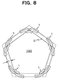
- FIG. 8 illustrates an exemplary configuration of a regular pentagonal charged particle orbit control device 100 (edge-type) having a two-cycle orbit.
- a bending magnet 1 provided at each vertex of the regular pentagon.
- Each bending magnet 1 bends the charged particle 3 such that the angle of emergence with respect to the angle of incidence becomes a given bending angle (72 degrees).
- each bending magnet 1 there exist two orbits through which the charged particle 3 passes.
- the bending angle and relative position of each bending magnet are prescribed such that every time the charged particle 3 passes through each bending magnet 1, the orbit of the charged particle 3 in each bending magnet 1 alternately switches between the two orbits.
- the bending angle and relative position of each bending magnet 1 are prescribed such that every time the charged particle 3 passes through, the incident position of the charged particle 3 incident on each bending magnet 1 alternately switches between two positions. The incident position alternately switches, but since the bending angle is fixed in each bending magnet 1, the orbit of the charged particle 3 passing through the bending magnets 1 forms two types.
- each bending magnet 1 it is necessary to design each bending magnet 1 such that the distance L and the length of the straight parts of the orbit of the charged particle 3 are suited to the usage of the charged particle orbit control device 100. Also, although the pole tips of the bending magnets 1 are orthogonal to the orbit, an arbitrary angle is typically selectable.
- each bending magnet 1 is disposed such that the orbit of the charged particle 3 alternately switches every time the charged particle 3 passes through a bending magnet 1. For this reason, the charged particle orbit control device 100 additionally exhibits the following advantages.
- the charged particle orbit control device 100 differs from the foregoing first embodiment in that the charged particle 3 returns to the original orbit in three cycles rather than two cycles.
- m 3.
- FIG. 9 illustrates particle orbit bends in a charged particle orbit control device 100 according to the present embodiment. As illustrated in FIG. 9 , the particle orbit bends are constructed on the basis of a regular hendecagon.
- the orbit of the first cycle of the charged particle 3 is indicated in bold lines.
- the orbit of the second cycle of the charged particle 3 is indicated in solid lines.
- the orbit of the third cycle of the charged particle 3 is indicated in dotted lines. As illustrated in FIG. 9 , with these particle orbit bends, the charged particle 3 returns to the original orbit in three cycles.
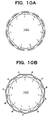
- FIG. 10A illustrates an exemplary configuration of a charged particle orbit control device 100 according to the present embodiment.
- a bending magnet 1 is respectively disposed at each vertex of a regular hendecagon.
- the bending magnet 1 bends a charged particle 3 arriving from a neighboring vertex on one side towards the vertex neighboring the neighboring vertex on the other side. Also, the bending magnet 1 bends a charged particle 3 arriving from another vertex neighboring the neighboring vertex on the one side towards the neighboring vertex on the other side.
- the two neighboring bending magnets at each vertex of the regular hendecagon work as a group to bend (deflect) the orbit of the charged particle 3 towards another vertex that neighbors the neighboring vertices.
- this type of lattice will also be called a double-bend-type.
- this charged particle orbit control device 100 it is also possible to additionally dispose, between each of the vertices of the regular hendecagon, a bending magnet 4 that bends the charged particle 3 exiting one vertex towards a neighboring vertex.
- a bending magnet 4 that bends the charged particle 3 exiting one vertex towards a neighboring vertex.
- the three bending magnets made up of the bending magnets 1 at two adj acent vertices of the regular hendecagon, with the addition of a bending magnet 4 disposed therebetween, work as a group to bend the orbit of the charged particle 3.
- this type of lattice will also be called a triple-bend-type.
- the lattice in which the number of cycles m is 3 is not limited to being based on a regular hendecagon.
- FIG. 11A illustrates double-bend-type particle orbit bends based on a regular heptagon
- FIG. 11B illustrates the layout of the bending magnets 1 in such a lattice
- FIG. 11C illustrates triple-bend-type particle orbit bends based on a regular heptagon
- FIG. 11D illustrates the layout of the bending magnets 1 and 4 in such a lattice.
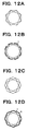
- FIG. 12A illustrates double-bend-type particle orbit bends based on a regular octagon
- FIG. 12B illustrates the layout of the bending magnets 1 in such a lattice
- FIG. 12C illustrates triple-bend-type particle orbit bends based on a regular octagon
- FIG. 12D illustrates the layout of the bending magnets 1 and 4 in such a lattice.
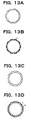
- FIG. 13A illustrates double-bend-type particle orbit bends based on a regular decagon
- FIG. 13B illustrates the layout of the bending magnets 1 in such a lattice
- FIG. 13C illustrates triple-bend-type particle orbit bends based on a regular decagon
- FIG. 13D illustrates the layout ofthe bending magnets 1 and 4 in such a lattice.
- FIG. 14A illustrates double-bend-type particle orbit bends based on a regular hendecagon
- FIG. 14B illustrates the layout of the bending magnets 1 in such a lattice
- FIG. 14C illustrates triple-bend-type particle orbit bends based on a regular hendecagon
- FIG. 14D illustrates the layout of the bending magnets 1 and 4 in such a lattice.
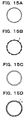
- FIG. 15A illustrates double-bend-type particle orbit bends based on a regular tridecagon
- FIG. 15B illustrates the layout ofthe bending magnets 1 in such a lattice
- FIG. 15C illustrates triple-bend-type particle orbit bends based on a regular tridecagon
- FIG. 15D illustrates the layout ofthe bending magnets 1 and 4 in such a lattice.
- the number of cycles in which the charged particle 3 returns to the original orbit is three cycles, with three ring cycles making one period.
- the path length is substantially tripled or more within the same installation area. Lengthening the path length exhibits the advantages indicated below.
- the charged particle orbit control device 100 includes multiple bending magnets 1 that bend the charged particle 3, and the bending angle and relative position of each bending magnet 1 are prescribed such that every time the charged particle 3 passes through, the orbit of the charged particle 3 in each bending magnet 1 alternately switches between the two orbits.
- the bending angle and relative position of each bending magnet 1 are prescribed such that every time the charged particle 3 passes through, the incident position of the charged particle 3 incident on each bending magnet 1 alternately switches between two positions.
- the bending angle and relative position of each bending magnet 1 are prescribed such that every time the charged particle 3 passes through, the incident angle of the charged particle incident on each bending magnet 1 alternately switches between two angles.
- the charged particle orbit control device 100 has the following advantages.
- the charged particle orbit control device 100 in FIG. 16 is a device able to switch the number of cycles m over which the charged particle 3 returns to the original orbit.
- the charged particle orbit control device 100 is equipped with bending magnets 1 and 4.
- the charged particle orbit control device 100 is additionally equipped with an electromagnet power source 5 that controls the magnetic force of each of the bending magnets 1 and 4.
- an electromagnet power source 5 that controls the magnetic force of each of the bending magnets 1 and 4.
- the lattice in the charged particle orbit control device 100 is based on a regular heptagon.
- n 7.
- the number n is a natural number that is neither a multiple of 2 nor a multiple of 3.
- FIG. 17A illustrates triple-bend-type particle orbit bends based on a regular heptagon.
- FIG. 17B illustrates a three-cycle orbit of the charged particle 3 according to a triple-bend-type lattice.
- the electromagnet power source 5 sets the magnetic force of the bending magnets 1 centrally positioned on each edge of the regular heptagon to a magnitude such that a charged particle 3 arriving from a neighboring bending magnet 4 on one side is bent towards another bending magnet 1 centrally positioned on the edge neighboring the neighboring edge on the other side, and such that a charged particle 3 arriving from another bending magnet 1 centrally positioned on the edge neighboring the neighboring edge on the one side is bent towards the neighboring bending magnet 4.
- the electromagnet power source 5 also sets the magnitude of the magnetic force of the bending magnets 4 to a magnitude such that a charged particle 3 exiting a neighboring bending magnet 1 on one side is bent towards a neighboring bending magnet 1 on the other side.
- FIG. 17C illustrates a two-cycle orbit of the charged particle 3 according to a triple-bend-type lattice.
- the electromagnet power source 5 sets the magnetic force of the bending magnets 1 to a magnitude such that the charged particle 3 passes through every other bending magnet 1 at the center of each edge of the regular heptagon. In this case, the charged particle 3 does not pass through the bending magnets 4, and thus the magnitude of the magnetic force of the bending magnets 4 is set to 0.
- FIG. 17D illustrates a one-cycle orbit of the charged particle 3 according to such a lattice.
- the electromagnet power source 5 sets the magnitude of the magnetic force of the bending magnets 1 to 0, and sets the magnitude of the magnetic force of the bending magnets 4 such that the charged particle 3 passes through every vertex of the regular heptagon along the edges.
- FIG. 18A illustrates double-bend-type particle orbit bends based on a regular heptagon.
- FIG. 18B illustrates a three-cycle orbit of the charged particle 3 according to a double-bend-type lattice.
- the electromagnet power source 5 sets the magnitude of the magnetic force of the bending magnets 1 positioned at each vertex of the regular heptagon to a magnitude such that a charged particle 3 arriving from a neighboring vertex on one side is bent towards the vertex neighboring the neighboring vertex on the other side, and such that a charged particle 3 arriving from another vertex neighboring the neighboring vertex on the one side is bent towards the neighboring vertex on the other side.
- FIG. 18C illustrates a two-cycle orbit of the charged particle 3 according to a double-bend-type lattice.
- the electromagnet power source 5 sets the magnitude of the magnetic force of the bending magnets 1 to a magnitude such that the charged particle 3 passes through every other vertex of the regular heptagon.
- FIG. 18D illustrates a one-cycle orbit of the charged particle 3 according to such a lattice.
- the electromagnet power source 5 sets the magnitude of the magnetic force of the bending magnets 1 to a magnitude such that the charged particle 3 passes through every vertex of the regular heptagon along the edges.
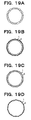
- FIG. 19A illustrates triple-bend-type particle orbit bends based on a regular hendecagon.
- FIGS. 19B to 19D respectively illustrate a three-cycle orbit, a two-cycle orbit, and a one-cycle orbit of the charged particle 3 according to a triple-bend-type lattice based on a regular hendecagon. Switching among these ring orbits is likewise possible by having the electromagnet power source 5 adjust the magnitudes of the magnetic force of the bending magnets 1 and 4 as described above.
- FIG. 20A illustrates double-bend-type particle orbit bends based on a regular hendecagon.
- FIGS. 20B to 20D respectively illustrate a three-cycle orbit, a two-cycle orbit, and a one-cycle orbit of the charged particle 3 according to a double-bend-type lattice based on a regular hendecagon. Switching among these ring orbits is likewise possible by having the electromagnet power source 5 adjust the magnitude of the magnetic force of the bending magnets 1 as described above.
- the charged particle orbit control device 100 is able to switch a single period of the charged particle 3 from one cycle to three cycles. According to this charged particle orbit control device 100, it becomes possible to adjust the path length of the orbit of the charged particle 3 according to the intended purpose.
- edge-type lattices typically have fewer bending magnets and more straight lines compared to vertex-type lattices.
- edge-type lattices since the straight-line orbit in the first cycle and the straight-line orbit in the second cycle tend to be in proximity, the need to separate the two straight-line orbits to some degree should be noted.
- the lattice in the charged particle orbit control device 100 is not limited to being in accordance with the foregoing embodiments.
- FIGS. 21 and 22 it is also possible to form a lattice based on a regular triangle, as illustrated in FIGS. 21 and 22 .
- the bending magnets are manufactured and adjusted such that, with respect to the orbit of a charged particle inside the bending magnets installed at each vertex of the regular triangle, the bending angle is small on the inner orbit, and the bending angle is large on the outer orbit.
- a charged particle alternately passes through the inner and outer sides every time the charged particle passes through a neighboring bending magnet.
- a lattice based on a regular pentagon
- an outer vertex and an inner vertex are respectively disposed in correspondence with each vertex of the regular pentagon, and the charged particle 3 assumes an orbit that alternately passes through the outer vertices and the inner vertices.
- the bending magnets are manufactured and adjusted such that, with respect to the orbit of a charged particle inside the bending magnets installed at each vertex of the regular pentagon, the bending angle is small on the inner orbit, and the bending angle is large on the outer orbit.
- a charged particle alternately passes through the inner and outer sides every time the charged particle passes through a neighboring bending magnet.
- each bending magnet 1 there exist two orbits through which the charged particle 3 passes.
- the bending angle and relative position of each bending magnet are prescribed such that every time the charged particle 3 passes through each bending magnet 1, the orbit of the charged particle 3 in each bending magnet 1 alternately switches between the two orbits.
- the bending angle and relative position of each bending magnet 1 are likewise prescribed such that every time the charged particle 3 passes through, the incident position of the charged particle 3 incident on each bending magnet 1 alternately switches between two positions. Also, in this charged particle orbit control device 100, the bending angle and relative position of each bending magnet are prescribed such that every time the charged particle 3 passes through, the incident angle of the charged particle incident on each bending magnet 1 alternately switches between two angles.
- each bending magnet 1 The strength of the magnetic field of each bending magnet 1 is prescribed such that the bending angle of a charged particle 3 incident on the inner side of the orbit becomes slightly less than 72 degrees, and such that the bending angle of a charged particle 3 incident on the outer side of the orbit becomes slightly larger than 72 degrees.
- a charged particle 3 passing through the inner orbit and incident on each bending magnet 1 heads towards the outer orbit, while a charged particle 3 passing through the outer orbit and incident on each bending magnet 1 heads towards the inner orbit.
- the orbit of the charged particle 3 intersects on the straight parts of the orbits in the charged particle orbit control device 100 illustrated in FIG. 23 .
- the orbit intersection angle at which the orbit intersects on the straight parts is determined by the distance between the inner and outer n-sided polygons, and the edge lengths thereof
- each bending magnet 1 it is still necessary to design each bending magnet 1 such that the length of the straight parts of the orbit of the charged particle 3 and the like are suited to the usage of the charged particle orbit control device 100. Although the pole tips of these bending magnets 1 are orthogonal to the orbit, an arbitrary angle is typically selectable.
- lattices in which the charged particle 3 returns to the original orbit in two cycles or three cycles the present invention is not limited thereto.
- n is a natural number that is not a multiple ofm.
- the bending magnet 1 has two intersecting orbits, as illustrated in FIG. 24 .
- the bending angle ⁇ 1 and the orbit intersection angle ⁇ 2 in a bending magnet 1 is computed geometrically.
- the two angles that characterize the structure of a bending magnet 1 in an charged particle orbit control device 100 having an n-sided polygonal shape and m cycles are summarized below, classified into the two types of the double-bend type and the triple-bend type.
- a single inner angle of the n-sided regular polygon 180(n-2)/n [deg.], and the total sum of bending angles ⁇ 1 becomes 360 ⁇ m [deg.].
- the total number of bending magnets 1 through which the charged particle 3 passes in one period becomes 2 ⁇ n.
- the bending angle ⁇ 1 of each bending magnet 1 becomes the following formula.
- the intersection angle ⁇ 2 between two orbits becomes the following formula. MATH.
- a single inner angle of the n-sided regular polygon becomes 180(n-2)/n [deg.], and the total sum of bending angles ⁇ 1 becomes 360 ⁇ m [deg.].
- the total number of bending magnets 1 through which the charged particle 3 passes becomes n for the bending magnets 4 in which the orbit does not intersect, and 2 ⁇ n for the bending magnets 1 in which the orbit does intersect.
- intersection angle ⁇ 2 between two orbits becomes the following formula.
- MATH. 5 ⁇ ⁇ 2 180 ⁇ m - 1 / n deg .
- Intersection angles ⁇ 1 in a triple-bend-type charged particle orbit control device 100 having an n-sided polygonal shape and m cycles are summarized in the following table.
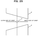
- a configuration is possible in which a magnetic field gradient is provided in each bending magnet 1 from the inner side to the outer side of the orbit of the charged particle 3.
- a magnetic field gradient is formed such that the magnetic force becomes stronger towards the inner side of the orbit for a charged particle 3 traveling in a direction orthogonal to the plane of the page. In so doing, it becomes possible to further lower the emittance of a particle beam formed by charged particles 3. Note that it is also possible to form a magnetic field gradient such that the magnetic force becomes stronger towards the outer side.
- each bending magnet 1 is disposed on the outer periphery of a regular polygon in the foregoing embodiments, the present invention is not limited thereto.
- various objects are disposed on the straight parts of the orbit of the charged particle 3.
- an undulator 10 is disposed on each straight part. In this way, since there are many straight parts in the charged particle orbit control device 100, it is possible to dispose many undulators 10.
- a charged particle orbit control device 100 accepts a charged particle 3 incident from multiple different positions, has multiple orbits for the charged particle 3 depending on the incident position, requiring bending magnets 1 that eject the charged particle 3 from multiple different positions according to the orbit. By providing such bending magnets 1, the advantages of the charged particle orbit control device 100 discussed above are exhibited.
- the present invention is not limited by the foregoing embodiments and drawings. Obviously, it is possible to modify the embodiments and drawings within a scope that does not alter the principal matter of the present invention. Essentially, the configuration is such that one period in the orbit of a charged particle has multiple cycles rather than one cycle.
- the present invention is suitable for use in a charged particle accelerator and charged particle storage ring, as discussed above.
Landscapes
- Physics & Mathematics (AREA)
- Engineering & Computer Science (AREA)
- Plasma & Fusion (AREA)
- Spectroscopy & Molecular Physics (AREA)
- Optics & Photonics (AREA)
- Particle Accelerators (AREA)
Applications Claiming Priority (2)
| Application Number | Priority Date | Filing Date | Title |
|---|---|---|---|
| JP2010283850 | 2010-12-20 | ||
| PCT/JP2011/079423 WO2012086612A1 (ja) | 2010-12-20 | 2011-12-19 | 荷電粒子軌道制御装置、荷電粒子加速器、荷電粒子蓄積リング及び偏向電磁石 |
Publications (2)
| Publication Number | Publication Date |
|---|---|
| EP2658352A1 true EP2658352A1 (de) | 2013-10-30 |
| EP2658352A4 EP2658352A4 (de) | 2015-05-20 |
Family
ID=46313881
Family Applications (1)
| Application Number | Title | Priority Date | Filing Date |
|---|---|---|---|
| EP11851567.5A Withdrawn EP2658352A4 (de) | 2010-12-20 | 2011-12-19 | Bahnenregelungsvorrichtung für geladene teilchen, beschleuniger für geladene teilchen, speicherring für geladene teilchen und ablenkungs-elektromagnet |
Country Status (4)
| Country | Link |
|---|---|
| US (1) | US8704464B2 (de) |
| EP (1) | EP2658352A4 (de) |
| JP (1) | JP5854518B2 (de) |
| WO (1) | WO2012086612A1 (de) |
Families Citing this family (1)
| Publication number | Priority date | Publication date | Assignee | Title |
|---|---|---|---|---|
| CN110798959A (zh) * | 2019-10-31 | 2020-02-14 | 复旦大学 | 一种多方向带电粒子束流转向装置 |
Family Cites Families (6)
| Publication number | Priority date | Publication date | Assignee | Title |
|---|---|---|---|---|
| JPH02299200A (ja) * | 1989-05-15 | 1990-12-11 | Fujitsu Ltd | シンクロトロン放射光発生装置 |
| JPH04112500A (ja) * | 1990-08-31 | 1992-04-14 | Fujitsu Ltd | シンクロトロン放射光発生用電子蓄積リング |
| JPH05182797A (ja) * | 1991-12-27 | 1993-07-23 | Ishikawajima Harima Heavy Ind Co Ltd | シンクロトロン |
| JPH0689800A (ja) * | 1992-09-04 | 1994-03-29 | Ishikawajima Harima Heavy Ind Co Ltd | 粒子加速器 |
| JP3389515B2 (ja) * | 1998-11-27 | 2003-03-24 | 住友重機械工業株式会社 | 蓄積リングへのビーム入射方法及び装置 |
| JP4257741B2 (ja) * | 2004-04-19 | 2009-04-22 | 三菱電機株式会社 | 荷電粒子ビーム加速器、荷電粒子ビーム加速器を用いた粒子線照射医療システムおよび、粒子線照射医療システムの運転方法 |
-
2011
- 2011-12-19 JP JP2012549810A patent/JP5854518B2/ja not_active Expired - Fee Related
- 2011-12-19 WO PCT/JP2011/079423 patent/WO2012086612A1/ja not_active Ceased
- 2011-12-19 US US13/995,606 patent/US8704464B2/en active Active
- 2011-12-19 EP EP11851567.5A patent/EP2658352A4/de not_active Withdrawn
Also Published As
| Publication number | Publication date |
|---|---|
| JP5854518B2 (ja) | 2016-02-09 |
| JPWO2012086612A1 (ja) | 2014-05-22 |
| EP2658352A4 (de) | 2015-05-20 |
| US20130270452A1 (en) | 2013-10-17 |
| US8704464B2 (en) | 2014-04-22 |
| WO2012086612A1 (ja) | 2012-06-28 |
Similar Documents
| Publication | Publication Date | Title |
|---|---|---|
| ES2901895T3 (es) | Diseño de acelerador lineal de alta frecuencia, compacto y de baja energía | |
| US8324841B2 (en) | Twin internal ion source for particle beam production with a cyclotron | |
| US12101869B2 (en) | Particle accelerator and particle beam therapy apparatus | |
| EP3264868A1 (de) | Einspritzsystem für zyklotron und betriebsverfahren für driftröhrenlinearbeschleuniger | |
| EP3024306B1 (de) | Hochstromzyklotron | |
| CN104703381B (zh) | 圆形加速器以及粒子线治疗装置 | |
| JP6053938B2 (ja) | 粒子線治療システム | |
| Holzer | Introduction to particle accelerators and their limitations | |
| EP2701468B1 (de) | Verfahren und System für stabile Dynamik und konstante Strahlenabgabe zur Beschleunigung von geladenen Teilchenstrahlen in einem nichtskalierenden Beschleuniger mit Gradientenmagnetfeld mit wechselnder Richtung | |
| EP2658352A1 (de) | Bahnenregelungsvorrichtung für geladene teilchen, beschleuniger für geladene teilchen, speicherring für geladene teilchen und ablenkungs-elektromagnet | |
| JP5362045B2 (ja) | 超電導コイル装置 | |
| Vonta et al. | Neutron-rich rare-isotope production from projectile fission of heavy nuclei near 20 MeV/nucleon beam energy | |
| Gonzalez et al. | rf chopper for prebunched radioactive ion beams | |
| Holzer | Introduction to longitudinal beam dynamics | |
| JP4276160B2 (ja) | 円形荷電粒子加速器およびその円形荷電粒子加速器の運転方法 | |
| Baartman et al. | 60 keV beam transport line and switch-yard for ISAC | |
| CN115812340B (zh) | 粒子加速器以及粒子线治疗装置 | |
| JP3574334B2 (ja) | 荷電粒子輸送装置 | |
| RU2546960C2 (ru) | Способ проведения реакции управляемого ядерного синтеза и устройство для его осуществления | |
| Molodozhentsev et al. | The focusing structure of the Prague proton synchrotron for hadron therapy | |
| JP2022176617A (ja) | セプタム電磁石、加速器および粒子線治療システム | |
| JP2017216190A (ja) | 加速器および粒子線照射装置 | |
| Medina et al. | Dynamic Aperture Studies for the FCC-ee | |
| Ilic et al. | Initial Conditions Corresponding to Optimal Ion Acceleration in the VINCY Cyclotron | |
| Pitthan | Using Octupoles for Background Control in Linear Colliders: an Exploratory Conceptual Study |
Legal Events
| Date | Code | Title | Description |
|---|---|---|---|
| PUAI | Public reference made under article 153(3) epc to a published international application that has entered the european phase |
Free format text: ORIGINAL CODE: 0009012 |
|
| 17P | Request for examination filed |
Effective date: 20130718 |
|
| AK | Designated contracting states |
Kind code of ref document: A1 Designated state(s): AL AT BE BG CH CY CZ DE DK EE ES FI FR GB GR HR HU IE IS IT LI LT LU LV MC MK MT NL NO PL PT RO RS SE SI SK SM TR |
|
| DAX | Request for extension of the european patent (deleted) | ||
| RA4 | Supplementary search report drawn up and despatched (corrected) |
Effective date: 20150416 |
|
| RIC1 | Information provided on ipc code assigned before grant |
Ipc: H05H 13/04 20060101AFI20150410BHEP |
|
| 17Q | First examination report despatched |
Effective date: 20160315 |
|
| STAA | Information on the status of an ep patent application or granted ep patent |
Free format text: STATUS: THE APPLICATION IS DEEMED TO BE WITHDRAWN |
|
| 18D | Application deemed to be withdrawn |
Effective date: 20170817 |