EP2701468B1 - Verfahren und System für stabile Dynamik und konstante Strahlenabgabe zur Beschleunigung von geladenen Teilchenstrahlen in einem nichtskalierenden Beschleuniger mit Gradientenmagnetfeld mit wechselnder Richtung - Google Patents
Verfahren und System für stabile Dynamik und konstante Strahlenabgabe zur Beschleunigung von geladenen Teilchenstrahlen in einem nichtskalierenden Beschleuniger mit Gradientenmagnetfeld mit wechselnder Richtung Download PDFInfo
- Publication number
- EP2701468B1 EP2701468B1 EP13181463.4A EP13181463A EP2701468B1 EP 2701468 B1 EP2701468 B1 EP 2701468B1 EP 13181463 A EP13181463 A EP 13181463A EP 2701468 B1 EP2701468 B1 EP 2701468B1
- Authority
- EP
- European Patent Office
- Prior art keywords
- magnet
- particle beam
- defocus
- sin
- focus
- Prior art date
- Legal status (The legal status is an assumption and is not a legal conclusion. Google has not performed a legal analysis and makes no representation as to the accuracy of the status listed.)
- Active
Links
Images

Classifications
-
- H—ELECTRICITY
- H05—ELECTRIC TECHNIQUES NOT OTHERWISE PROVIDED FOR
- H05H—PLASMA TECHNIQUE; PRODUCTION OF ACCELERATED ELECTRICALLY-CHARGED PARTICLES OR OF NEUTRONS; PRODUCTION OR ACCELERATION OF NEUTRAL MOLECULAR OR ATOMIC BEAMS
- H05H7/00—Details of devices of the types covered by groups H05H9/00, H05H11/00, H05H13/00
- H05H7/06—Two-beam arrangements; Multi-beam arrangements storage rings; Electron rings
-
- H—ELECTRICITY
- H05—ELECTRIC TECHNIQUES NOT OTHERWISE PROVIDED FOR
- H05H—PLASMA TECHNIQUE; PRODUCTION OF ACCELERATED ELECTRICALLY-CHARGED PARTICLES OR OF NEUTRONS; PRODUCTION OR ACCELERATION OF NEUTRAL MOLECULAR OR ATOMIC BEAMS
- H05H13/00—Magnetic resonance accelerators; Cyclotrons
- H05H13/08—Alternating-gradient magnetic resonance accelerators
- H05H13/085—Fixed-field alternating gradient accelerators [FFAG]
-
- H—ELECTRICITY
- H05—ELECTRIC TECHNIQUES NOT OTHERWISE PROVIDED FOR
- H05H—PLASMA TECHNIQUE; PRODUCTION OF ACCELERATED ELECTRICALLY-CHARGED PARTICLES OR OF NEUTRONS; PRODUCTION OR ACCELERATION OF NEUTRAL MOLECULAR OR ATOMIC BEAMS
- H05H13/00—Magnetic resonance accelerators; Cyclotrons
- H05H13/08—Alternating-gradient magnetic resonance accelerators
Definitions
- This application relates to continuous beam (CW) particle accelerators, and in particular to non-scaling fixed field alternating gradient (FFAG) machines in which charged particles are confined to isochronous orbits while being accelerated to a desired energy.
- CW continuous beam
- FFAG fixed field alternating gradient
- Accelerators are becoming increasingly important in medicine, clean energy and national security. Accelerators can be used for safer nuclear reactors, industrial irradiation, cancer therapy and cargo inspection.
- FFAG Fixed Field Alternating Gradient Accelerator
- scaling FFAG either spiral or radial-sector FFAGs
- CW operation CW operation
- the non-scaling FFAG was subsequently developed ( C. Johnstone, et al., "Fixed Field Circular Accelerator Designs", PAC'99, New York, P. 3068 .).
- the non-scaling FFAG was proposed for muon acceleration and utilized simple, combined function magnets like a synchrotron. However, it did not maintain a constant tune and was not suitable for an accelerator with a modest RF system and a slower acceleration cycle.
- U.S. Publication No. 2012/013274 describes a Non-Scaling FFAG Accelerator design, wherein the linear field condition is removed in order to realize advanced machine properties and optimal designs.
- the nonlinear field condition, or high-order field allows for more constant machine tune as a function of momentum or energy and more compact machines resulting in smaller apertures.
- Limits were set on the extraction and injection radii for compact machines in an optimizer search for stable solutions, but this is a constraint that does not reflect fundamental dynamics unlike limits required on cell phase advance or tune. These additional conditions were imposed only to guide the optimizer search but do not comprise a solution.
- the present invention provides an accelerator system according to claim 1 including a plurality of cells.
- Each cell includes a focus magnet and a defocus magnet each configured to create a magnetic field so as to confine and accelerate a particle beam, the focus magnet being configured to focus the particle beam in a horizontal direction and defocus the particle beam in a vertical direction, and the defocus magnet being configured to focus the particle beam in a vertical direction and defocus the particle beam in a horizontal direction.
- Each of the plurality of cells is configured to confine the particle beam in an isochronous orbit during acceleration.
- the accelerator system is a non-scaling fixed field alternating gradient particle accelerator (FFAG).
- the present invention relates to a method for controlling and accelerating a continuous particle beam in a non-scaling fixed field alternating gradient particle accelerator as defined in claim 7.
- magnet aperture as used herein is to define the difference between the beam radius at the accelerator extraction energy and the beam radius at the accelerator injection energy.
- the present invention provides a non-scaling FFAG accelerator in which charged particles are confined to isochronous orbits while being accelerated to a desired energy.
- the present invention provides a method by which a CW beam can be successfully controlled and accelerated in a non-scaling FFAG.
- the particle beam includes a proton beam.
- a CW non-scaling FFAG implies orbits in the accelerator are isochronous, wherein the revolution time of a particle beam as it accelerates is constant, and therefore a fixed-frequency (rather than a swept-frequency) Radio Frequency (RF) acceleration system can be employed.
- Fixed-frequency RF allows the particle beam to be continuously injected and accelerated.
- a stable CW accelerator design for a non-scaling FFAG can be achieved based on closed reference orbits (geometry), stable machine tune (focusing strength of field gradient combined with edge and centripetal focusing effects), and constraint of total path length according to an isochronous condition.
- Compact high-performance devices like FFAG-type accelerators and cyclotrons often are operated in a regime where space charge effects become significant.
- the strong focusing attribute, particularly in a vertical of the FFAG, implies some degree of mitigation of space-charge effects and possible stable acceleration of higher currents.
- FFAG fixed field alternating gradient
- the magnetic field strength at a given point in space does not vary in time, but unlike a conventional cyclotron, the FFAG generally has a stronger spatial variation with radius (a field gradient) to confine particles as they gain energy and their orbits change accordingly, thus the magnetic field frequently increases strongly as a function of radius.
- This strong field gradient which is an arbitrary gradient in the case of a non-scaling FFAG, not only allows stronger but also simultaneous control over important machine parameters relative to the conventional cyclotron.
- Reverse gradients can also be incorporated as in a synchrotron which has the added potential of improving vertical plane optics.
- isochronous invention is simultaneous control over machine tune, which is the integrated phase advance of a beam particle in one turn around the accelerator in combination with the beam particle's integrated path length over this turn.
- machine tune is the integrated phase advance of a beam particle in one turn around the accelerator in combination with the beam particle's integrated path length over this turn.
- Both the cell phase advance and the corresponding machine tune in a storage or accelerator ring are critical to confine beam and impose stable dynamics.
- the path length must also be controlled as a function of energy.
- a unique approach has been developed to control cell phase advance, and therefore machine tune, to promote stable beam optics along with path length, which is the basis for the isochronous invention described herein.
- an average radius is computed over a half or full cell so that the integrated path length is given by 2 ⁇ ⁇ R avg .
- Each cell contains a focus magnet (F magnet) and a defocus magnet (D magnet), each configured to create a magnetic field so as to confine and accelerate the particle beam.
- the F magnet is configured to focus the particle beam in a horizontal direction and defocus the particle beam in a vertical direction
- the D magnet is configured to focus the particle beam in a vertical direction and defocus the particle beam in a horizontal direction.
- the isochronous condition can be imposed by making the average radius scale with the relativistic velocity.
- Another implementation requires only an F magnet with edge focusing applied for vertical confinement.
- isochronous non-scaling FFAG designs presented herein are completely periodic and constructed entirely from a sequence of identical unit cells.
- the periodic cell structure exhibits reflective symmetry, and therefore the optics can be completely described by half of one of these cells.
- accelerators designed by the methods according to the isochronous condition disclosed herein are presented in three separate energy regimes:
- the isochronous condition in all machines restricts the extraction/injection radii to specific ratios depending on the relativistic velocity. As the energy becomes relativistic and the change in velocity as a function of energy and momentum decreases, the orbits become closer together with a corresponding decrease in machine aperture. Eventually the technical design becomes impractical with the required nonlinear field rise as machine radius becomes technically unachievable in the GeV range ( ⁇ 2 GeV at extraction).
- magnetic fields can be produced that are dominated by linear field gradients at low, nonrelativistic energies with field expansion becoming increasingly nonlinear as the energy transitions to a relativistic regime.
- the guide field magnets in these new designs retain simple wedge shapes, but field components, both linear and nonlinear, are systematically introduced to achieve the more advanced machine dynamics and operation required.
- the type and magnitude of the field content remain dependent on machine geometry, energy reach and application.
- the innovation developed involves the addition of an eighth, isochronous condition to seven fundamental dynamics and geometric equations for stable tune and acceleration, as presented in U.S. Patent No. 7,880,146 ("the '146 Patent").
- a solution for the seven fundamental equations exists that also makes the revolution time constant.
- the radial magnetic field, or B field can be solved as a function of radius and magnet parameters that preserves not only the required geometry and stable tune conditions, but also the revolution time, i.e. integrated path length scaled with velocity.
- the isochronous condition and the seven fundamental equations are added to an optimizer, or solver, which attempts to find solutions preserving all input accelerator dynamical conditions simultaneously.
- a strongly nonlinear field profile is particularly important for achieving isochronous orbits (CW operation) at high, relativistic energies ( ⁇ GeV) where cyclotrons break down and synchro-cyclotrons (swept-frequency, not CW) must be used.
- This invention is therefore particularly important for high-power, high energy applications such as Accelerator Driven Systems (ADS), ATW, as well as low-power, high-energy applications such as carbon cancer radiotherapy. These applications require energies in an energy regime where cyclotrons can become unfeasibly large or non-isochronous, or can encounter stability issues.
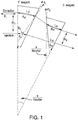
- Figures 1 and 2 show the relation of the parameters in the eight equations to the focus (F) and defocus (D) physical magnet design.
- the eight equations include thirteen variables listed below which describe the physical attributes of the individual magnets. Regarding the nomenclature of the variables, " e “ and “ i “ denote extraction and injection, subscripts " f “ and “ d “, horizontally focusing and defocusing magnets, and “ f “, the thin lens focal length.
- the thirteen variables include:
- the extraction field is related to the injection field according to an arbitrary conventional Taylor expansion of multipoles as shown below. Therefore, the number of actual free parameters depends on the order of the expansion. For example, to obtain a linear gradient the number of free variables remains at four ( B of , a f , B 0d , a d ), yielding a total of thirteen free parameters. Each consecutive field order adds two additional free parameters.
- a Taylor expansion is used here because it represents the conventional description of multipole content in a magnetic field.
- the order of the field varies depending on the optimal solution and desired criteria and is therefore selected by the optimizer. Not all of the field expansion coefficients set forth below are required in all of the machine designs, rather, the field expansions shown serve to indicate the highest order used in the current machine designs.
- B ef B 0 f + a f ⁇ x ef + b f ⁇ x ref 2 + c f ⁇ x ef 3 + d f ⁇ x ef 4 + e f ⁇ x ef 5 + f f ⁇ x ef 6
- B ed B 0 d + a d ⁇ x ed + b d ⁇ x ed 2 + c d ⁇ x ed 3 + d d ⁇ x ed 4 + e d ⁇ x ed 5 + f d ⁇ x ed 6
- B if B 0 f + a f ⁇ x ef ⁇ ⁇ x if + b f ⁇ x ef ⁇ ⁇ x if 2 + c f ⁇ x ef ⁇ ⁇ x if 3 + + d f ⁇ x ef ⁇ ⁇ x if 4 + e f ⁇ x ef ⁇ ⁇ x if 5 + f f ⁇ x ef ⁇ ⁇ x if 6
- B id B 0 d + a d ⁇ x ed ⁇ ⁇ x id + b d ⁇ x ed ⁇ ⁇ x id 2 + c d ⁇ x ed ⁇ ⁇ x id 3 + + d d ⁇ x ed ⁇ ⁇ x id 4 + e d ⁇ x ed ⁇ ⁇ x id 5 + f d ⁇ x ed ⁇ ⁇ x id 6
- the field expansion is expressed in terms of variables relative to the extraction orbit; for example, ⁇ x if is the distance from injection to extraction in the F magnet such that the increasing values for the field correspond to increasing values of radius.
- the value ⁇ x ef is the distance from the point about which the magnetic (B) field is radially expanded to the position of the extraction orbit. At that expansion point, the field has the value B 0f .
- the value for this position variable, ⁇ x ef along with the variable B 0f , is selected by the optimizer.
- the general radial parameter, ⁇ x which characterizes the field profile, is a coordinate relative to the extraction orbit and is not the same as the average physical radius, R e , of the extraction orbit used to compute the integrated path length of the beam at extraction.
- the extraction orbit often proves to be the most critical for most designs because it generally requires the highest field values and is used as the starting point in these machine designs. It is possible to expand from the injection orbit, but critical computational accuracy is lost in solving for a solution starting with small values and integrating to large ones, thus compromising the optimizer when solving for the best solution.
- the magnetic field is treated as a thick lens.
- thick-lens formulae are used to calculate and constrain the tune which is given by the traces of the thick-lens linear matrices.
- the following equations generate the half-cell tune or phase advance in the horizontal and vertical for a FDF magnet configuration as calculated from the half-cell thick lens matrices, wherein a full cell is constructed from a half cell using reflective symmetry.
- the matrices start at the midpoint of a long straight, which is inserted between the two F magnets center, and end at the center of the D magnet for an FDF magnet configuration, or similarly, a long straight may be inserted between two D magnets for a DFD magnet configuration.
- the thick-lens tune equations are not impacted, and only an additional parameter, a length of the long straight, is required. The value of the long straight length is not free, but is fixed by the designer.
- the drift is the distance between the F and D magnets and the gradient
- D l is the half length of a drift inserted between the F magnets as in Figure 3 (this drift can also be inserted between the two D magnets in a DFD configuration).
- the symbol ⁇ is the phase advance or tune across the half cell.
- phase advance or cell-tune tune relationship will be used below to demonstrate different expressions for the same constraint equations and to relate physical properties of the magnet layout with the cell phase advance. It should also be noted that a negative ⁇ reverses the sign of the edge crossing term in the vertical equation. The edge-angle convention here is opposite many conventional usages such that a positive value of ⁇ corresponds to an outward bend wherein path length increases from injection to extraction.
- the first four equations serve to specify the machine tune at injection and extraction (when multiplied by twice the number of half cells).
- the thin lens approximation is used in order to obtain a general equation form, followed by an equation form representing the optimal linear-gradient solution.
- the general equations reduce to a simpler form when the field expansion is truncated after the first coefficient and after the optimal solution is introduced.
- Geometric closure of reference orbits is imposed in the fifth equation (set forth below), in which the net bend per cell is set equal at injection and extraction.
- the net cell bend must be the appropriate fraction of 2 ⁇ per number of cells comprising a full ring:
- the derivations of the path length must also include the angle of the trajectories through the F and D magnets at injection and extraction, ⁇ if , ⁇ id , ⁇ ef , and ⁇ d .
- the derivation assumes a starting point at the center of the F magnet which is a symmetry point so all orbits are parallel which is propagated across the drift, D e or D i , and then through the D magnet with a varying crossing angle.
- the crossing angle which varies with energy complicates the derivation through the D magnet.
- Non-parallel orbits are one characteristic of a non-scaling FFAG.
- Equations at intermediate energies can be utilized primarily at higher field orders to keep the tune from oscillating outside of stable regions between injection and extraction. This is a known property of nonlinear expansions, specifically field expansions, and not unique to this accelerator design methodology.
- Nonlinear field magnetic systems are commonplace in standard accelerator design. Synchrotrons, for example, utilize sextupole and octupole corrector fields in specific "families" to control tune as a function of energy or offset from the reference orbit.
- Intermediate energies facilitate the optimizer search by limiting the solution set. This practice is applied for isochronous performance by constraining the path length between injection and extraction, especially at relativistic energies where the velocity is a strongly nonlinear equation of momentum and therefore integrated B field.
- the intermediate equations shown below are identical to those describing injection and extraction as described above, where n is simply a sequence number to identify the intermediate point.
- each cell includes a wedge-shaped focus magnet with no defocus magnet, the F magnet being configured to create a magnetic field so as to confine and accelerate the particle beam and configured to focus the particle beam in both a horizontal direction and in a vertical direction.
- the focus magnet parameters are related by the following equations, which include thin-lens approximations. In order to obtain vertical focusing and vertical beam stability, ⁇ f ⁇ 0.
- the optimizer is used to find solutions to the set of fundamental equations given the imposed isochronous condition so as to solve magnetic component designs.
- Acceptable ranges can be imposed on almost any of the parameters to achieve a stable dynamical solution within given technical constraints.
- Technically infeasible designs for example, can be eliminated by setting limits to exclude nonphysical magnet lengths and unachievable field strengths.
- Other parameters, such as the magnet spacing were also chosen based upon technical considerations. By setting limits on the extraction and injection radii, the footprint and aperture of the machine can be controlled, often a critical design consideration.
- the field profile was determined based on the energy regime, with the reference radii scaling with velocity.
- the field gradient is at most linear.
- the momentum deviates from direct proportionality to velocity at near relativistic proton energies ( ⁇ 100 MeV)
- nonlinear terms become increasingly important.
- the magnetic field rises strongly with radius and a highly nonlinear field content is required.
- Figure 1 includes a layout of half of a configuration for a standard unit cell which utilizes a pair of FFAG magnets.
- Figure 1 consists of half of a horizontally focusing (F) magnet on the left and half of a horizontally defocusing (D) magnet on the right. Because the figure displays half of each magnet, it is reflected at either end to produce the full-cell unit.
- Figure 1 includes the following parameters:
- Figure 2 includes a layout of half of a configuration for a standard unit cell which utilizes a pair of FFAG magnets and includes the following additional parameters where B is expressed in Tesla:
- a straight, magnet-free section can be inserted immediately before the half F magnet (effectively at its centerline) and/or after the half D magnet (also at its centerline). Insertion of a straight section for injection, extraction or acceleration purposes at points of reflective symmetry minimizes the impact on the stable optics but allows a powerful long section for acceleration, diagnostics, injection and extraction purposes.
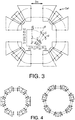
- Figure 3 shows an entire FFAG magnet system as constructed from four identical unit cells as shown in Figures 1 and 2 to form a recirculating ring layout for a 0.25 - 1GeV machine.
- the number of cells can vary depending on energy, ring size, and magnet aperture.
- Figure 4 shows a 6- and a 7-cell configuration of a 0.33 to 1 GeV isochronous FFAG magnet system constructed from the unit cell shown in Figures 1 and 2 .
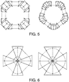
- Figure 5 shows the full ring layouts for 4- and 5-cell versions of a 30-330MeV isochronous FFAG accelerators constructed from the unit cell shown in Figures 1 and 2 .
- FIG. 6 another unit-cell configuration utilizes only wedge-shaped F magnets.
- the vertical beam envelope is confined through edge focusing effects as is done in cyclotron beam dynamics.
- This latter single-magnet ring is very similar to a cyclotron with a strong gradient and has not been proposed or implemented in any other work for a nonscaling FFAG.
- a long straight could be inserted at the centerline of the F magnets effectively splitting each single magnet into two components.
- a strong gradient causes strong edge focusing in the vertical via the edge angle, thus much stronger than the "flutter" or vertical tune of cyclotrons which have more constant radial fields and dips or "valleys" in the azimuthal field rather than open spaces between magnets.
- the accelerator disclosed in Fig.6 is an example useful for the understanding of the present invention.
- the velocity is proportional to momentum and momentum tracks the integrated magnetic field.
- This linear proportionality translates into a predominately linear increase in magnetic field or path length (a strong edge angle) with radius to maintain isochronous orbits.
- This linear gradient or quadrupole field is superimposed on a constant dipole field for the guide magnets.
- a linear gradient without strong higher order multipole components was also sufficient to contain the tune variation and permit beam stability (some curvature of the magnetic field gradient was needed for optimizing isochronous trajectories starting about 6 MeV).
- Table 1a General Parameters of a 50 keV to 8 MeV nonscaling FFAG, 1T version Parameter Unit Injection Extraction Energy Range MeV 0.050 8.0 Tune/cell ( ⁇ x / ⁇ y ) 2 ⁇ -rad 0.265/0.295 0.265/0.295 Machine Tune ( ⁇ x / ⁇ y ) 2 ⁇ -rad 1.060/1.180 1.060/1.180 Average Radius m 0.063 0.800 No.
- Table 2 General parameters for an initial 4-cell, 30-330MeV FFAG. Parameter Unit Injection Intermediate Extraction Energy Range MeV 30 151 330 Tune/cell ( ⁇ x / ⁇ y ) 2 ⁇ -rad 0.264/0.366 0.358/0.405 -/0.441 Machine Tune ( ⁇ x / ⁇ y ) 2 ⁇ -rad 1.056/1.464 1.432/1.620 -/1.764 Average Radius m 1.923 4.064 5.405 No.
- Table 4 General parameters 4-cell, 0.25 to 1-GeV FFAG. Parameter Unit Injection Intermediate Extraction Energy Range MeV 250 585 1000 Tune/cell ( ⁇ x / ⁇ y ) 2 ⁇ -rad 0.380/0.237 0.400/0.149 0.383/0.242 Machine Tune ( ⁇ x / ⁇ y ) 2 ⁇ -rad 1.520/0.948 1.600/0.596 1.532/0.968 Average Radius m 3.419 4.307 5.030 No.
Landscapes
- Physics & Mathematics (AREA)
- Engineering & Computer Science (AREA)
- Plasma & Fusion (AREA)
- Spectroscopy & Molecular Physics (AREA)
- Particle Accelerators (AREA)
Claims (7)
- Beschleunigersystem, umfassend eine Mehrzahl von Zellen, wobei jede Zelle einen Fokussiermagnet (F) und einen Defokussiermagnet (D) umfasst, welche in einer FDF- oder DFD-Magnetkonfiguration angeordnet sind, wobei jeder Fokussiermagnet und jeder Defokussiermagnet konfiguriert ist, um ein Magnetfeld zu erzeugen, derart, dass ein Teilchenstrahl eingeschlossen und beschleunigt wird, wobei der Fokussiermagnet konfiguriert ist, um den Teilchenstrahl in einer horizontalen Richtung zu fokussieren und den Teilchenstrahl in einer vertikalen Richtung zu defokussieren, und wobei der Defokussiermagnet konfiguriert ist, um den Teilchenstrahl in einer vertikalen Richtung zu fokussieren und den Teilchenstrahl in einer horizontalen Richtung zu defokussieren,
wobei jede der Mehrzahl von Zellen konfiguriert ist, um den Teilchenstrahl während der Beschleunigung in einem isochronen Orbit einzuschließen,
wobei das Beschleunigersystem ein nicht-skalierender Teilchenbeschleuniger mit festem Feld und alternierendem Gradienten (FFAG-Teilchenbeschleuniger) ist;
wobei der Fokussiermagnet durch die folgenden Fokussierparameter spezifiziert ist:ein Magnetfeld des Fokussiermagneten bei Injektion, Bif,ein Magnetfeld des Fokussiermagneten bei Extraktion, Bef,eine halbe Länge des Fokussiermagneten bei Injektion, Lif,eine halbe Länge des Fokussiermagneten bei Extraktion, Lef,einen linearen Kantenwinkel für den Fokussiermagnet, ηf, undeine Distanz vom Injektionsorbit zum Extraktionsorbit in dem Fokussiermagnet, δxif;wobei der Defokussiermagnet durch die folgenden Defokussierparameter spezifiziert ist:ein Magnetfeld des Defokussiermagneten bei Injektion, Bid,ein Magnetfeld des Defokussiermagneten bei Extraktion, Bed,eine halbe Länge des Defokussiermagneten bei Injektion, Lid,eine halbe Länge des Defokussiermagneten bei Extraktion, Led,einen linearen Kantenwinkel für den Defokussiermagnet, ηd, undeine Distanz vom Injektionsorbit zum Extraktionsorbit in dem Defokussiermagnet, δxid,wobei das Beschleunigersystem spezifiziert ist durch die Fokussierparameter, die Defokussierparameter und die folgenden zusätzlichen Parameter:De, eine Driftdistanz zwischen den Fokussier- und Defokussiermagneten bei Extraktion,Di, eine Driftdistanz zwischen den Fokussier- und Defokussiermagneten bei Injektion,Dl, eine halbe Länge einer Drift, welche im Falle einer FDF-Magnetkonfiguration zwischen Fokussiermagneten benachbarter Zellen oderim Falle einer DFD-Magnetkonfiguration zwischen Defokussiermagneten benachbarter Zellen eingefügt ist,Nsectors, eine Anzahl periodischer Zellen,einen horizontaler Halbzellen-Tune und einen vertikalen Halbzellen-Tune ϕH und ϕV; undwobei die Injektionsdrift (Di) und die Injektionsradien Ri(avg) und die Extraktionsradien Re(avg) durch De und Nsectors ausgedrückt werden können;
wobei das Beschleunigersystem dadurch gekennzeichnet ist, dass die Fokussierparameter und die Defokussierparameter, in der Näherung einer dünnen Linse, durch die folgenden Gleichungen in Beziehung stehen, um die Teilchen des Teilchenstrahls während der Beschleunigung in einem dynamisch stabilen isochronen Orbit einzuschließen:


wobei der horizontale Halbzellen-Tune und der vertikale Halbzellen-Tune ϕH und ϕV bereitgestellt sind durch:

- Beschleunigersystem nach Anspruch 1, wobei die Mehrzahl von Zellen 4 Zellen umfasst, eine Magnetapertur ungefähr 3,482 m beträgt, eine lange Gerade ungefähr 2 m beträgt und ein isochrones Verhalten ungefähr ±0,7 % beträgt, wobei bei einer Injektion des Teilchenstrahlsder Teilchenstrahl eine Strahlenergie von ungefähr 30 MeV beinhaltet,ein Radius des Teilchenstrahls ungefähr 1,923 m beträgt,eine F/D-Trennung einen Magnetabstand von ungefähr 0,435 m beinhaltet,das Magnetfeld des F-Magneten ungefähr 0,97 T beträgt,das Magnetfeld des D-Magneten ungefähr 0 T beträgt,eine Magnetlänge des F-Magneten ungefähr 1,28 m beträgt undeine Magnetlänge des D-Magneten ungefähr 0,10 m beträgt undwobei bei einer Extraktion des Teilchenstrahlsder Teilchenstrahl eine Strahlenergie von bis zu 330 MeV beinhaltet,ein Radius des Teilchenstrahls ungefähr 5,405 m beträgt,eine F/D-Trennung einen Magnetabstand von ungefähr 0,613 m beinhaltet,das Magnetfeld des F-Magneten ungefähr 1,51 T beträgt,das Magnetfeld des D-Magneten ungefähr -0,16 T beträgt,eine Magnetlänge des F-Magneten ungefähr 3,18 m beträgt undeine Magnetlänge des D-Magneten ungefähr 1,04 m beträgt.
- Beschleunigersystem nach Anspruch 1, wobei die Mehrzahl von Zellen 5 Zellen umfasst, eine Magnetapertur ungefähr 3,445 m beträgt, eine lange Gerade ungefähr 2 m beträgt und ein isochrones Verhalten ungefähr ±1,26 % beträgt, wobei bei einer Injektion des Teilchenstrahlsder Teilchenstrahl eine Strahlenergie von ungefähr 30 MeV beinhaltet,ein Radius des Teilchenstrahls ungefähr 2,983 m beträgt,eine F/D-Trennung einen Magnetabstand von ungefähr 0,493 m beinhaltet,das Magnetfeld des F-Magneten ungefähr 1,07 kG beträgt,das Magnetfeld des D-Magneten ungefähr 0 kG beträgt,eine Magnetlänge des F-Magneten ungefähr 0,94 m beträgt undeine Magnetlänge des D-Magneten ungefähr 0,1 m beträgt undwobei bei einer Extraktion des Teilchenstrahlsder Teilchenstrahl eine Strahlenergie von bis zu 330 MeV beinhaltet,ein Radius des Teilchenstrahls ungefähr 6,428 m beträgt,eine F/D-Trennung einen Magnetabstand von ungefähr 0,549 m beinhaltet,das Magnetfeld des F-Magneten ungefähr 1,53 kG beträgt,das Magnetfeld des D-Magneten ungefähr -0,16 kG beträgt,eine Magnetlänge des F-Magneten ungefähr 2,58 m beträgt undeine Magnetlänge des D-Magneten ungefähr 1,20 m beträgt.
- Beschleunigersystem nach Anspruch 1, wobei die Mehrzahl von Zellen 4 Zellen umfasst, eine Magnetapertur ungefähr 1,611 m beträgt, eine lange Gerade ungefähr 2 m beträgt und ein isochrones Verhalten ungefähr ±3 % beträgt, wobei bei einer Injektion des Teilchenstrahlsder Teilchenstrahl eine Strahlenergie von ungefähr 250 MeV beinhaltet,ein Radius des Teilchenstrahls ungefähr 3,419 m beträgt,eine F/D-Trennung einen Magnetabstand von ungefähr 0,289 m beinhaltet,das Magnetfeld des F-Magneten ungefähr 1,62 kG beträgt,das Magnetfeld des D-Magneten ungefähr -0,14 kG beträgt,eine Magnetlänge des F-Magneten ungefähr 1,17 m beträgt undeine Magnetlänge des D-Magneten ungefähr 0,38 m beträgt undwobei bei einer Extraktion des Teilchenstrahlsder Teilchenstrahl eine Strahlenergie von bis zu 1000 MeV beinhaltet,ein Radius des Teilchenstrahls ungefähr 5,030 m beträgt,eine F/D-Trennung einen Magnetabstand von ungefähr 0,505 m beinhaltet,das Magnetfeld des F-Magneten ungefähr 2,35 kG beträgt,das Magnetfeld des D-Magneten ungefähr -0,42 kG beträgt,eine Magnetlänge des F-Magneten ungefähr 1,94 m beträgt undeine Magnetlänge des D-Magneten ungefähr 1,14 m beträgt.
- Beschleunigersystem nach Anspruch 1, wobei die Mehrzahl von Zellen 6 Zellen umfasst, eine Magnetapertur ungefähr 1,588 m beträgt, eine lange Gerade ungefähr 2 m beträgt und ein isochrones Verhalten ungefähr ±0,9 % beträgt, wobei bei einer Injektion des Teilchenstrahlsder Teilchenstrahl eine Strahlenergie von ungefähr 330 MeV beinhaltet,ein Radius des Teilchenstrahls ungefähr 5,498 m beträgt,eine F/D-Trennung einen Magnetabstand von ungefähr 0,696 m beinhaltet,das Magnetfeld des F-Magneten ungefähr 1,5 kG beträgt,das Magnetfeld des D-Magneten ungefähr -0,0 kG beträgt,eine Magnetlänge des F-Magneten ungefähr 1,96 m beträgt undeine Magnetlänge des D-Magneten ungefähr 0,20 m beträgt undwobei bei einer Extraktion des Teilchenstrahlsder Teilchenstrahl eine Strahlenergie von bis zu 1000 MeV beinhaltet,ein Radius des Teilchenstrahls ungefähr 7,086 m beträgt,eine F/D-Trennung einen Magnetabstand von ungefähr 0,500 m beinhaltet,das Magnetfeld des F-Magneten ungefähr 1,8 kG beträgt,das Magnetfeld des D-Magneten ungefähr -3,8 kG beträgt,eine Magnetlänge des F-Magneten ungefähr 4,09 m beträgt undeine Magnetlänge des D-Magneten ungefähr 0,20 m beträgt.
- Beschleunigersystem nach Anspruch 1, wobei die Mehrzahl von Zellen 7 Zellen umfasst, eine Magnetapertur ungefähr 0,772 m beträgt, eine lange Gerade ungefähr 2 m beträgt und ein isochrones Verhalten ungefähr ±1,2 % beträgt, wobei bei einer Injektion des Teilchenstrahlsder Teilchenstrahl eine Strahlenergie von ungefähr 330 MeV beinhaltet,ein Radius des Teilchenstrahls ungefähr 4,354 m beträgt,eine F/D-Trennung einen Magnetabstand von ungefähr 0,300 m beinhaltet,das Magnetfeld des F-Magneten ungefähr 3,3 kG beträgt,das Magnetfeld des D-Magneten ungefähr -0,07 kG beträgt,eine Magnetlänge des F-Magneten ungefähr 0,79 m beträgt undeine Magnetlänge des D-Magneten ungefähr 0,25 m beträgt, undwobei bei einer Extraktion des Teilchenstrahlsder Teilchenstrahl eine Strahlenergie von bis zu 1000 MeV beinhaltet,ein Radius des Teilchenstrahls ungefähr 5,651 m beträgt,eine F/D-Trennung einen Magnetabstand von ungefähr 0,502 m beinhaltet,das Magnetfeld des F-Magneten ungefähr 3,8 kG beträgt,das Magnetfeld des D-Magneten ungefähr -3,0 kG beträgt,eine Magnetlänge des F-Magneten ungefähr 1,67 m beträgt undeine Magnetlänge des D-Magneten ungefähr 0,25 m beträgt.
- Verfahren zum Steuern und Beschleunigen eines kontinuierlichen Teilchenstrahls in einem nicht-skalierenden Teilchenbeschleuniger mit festem Feld und alternierendem Gradienten, umfassend:Bereitstellen einer Mehrzahl von Zellen, wobei jede Zelle einen Fokussiermagnet (F) und einen Defokussiermagnet (D) umfasst, welche in einer FDF- oder DFD-Magnetkonfiguration angeordnet sind, wobei jeder Fokussiermagnet und jeder Defokussiermagnet konfiguriert ist, um ein Magnetfeld zu erzeugen, derart, dass der Teilchenstrahl eingeschlossen und beschleunigt wird, wobei der Fokussiermagnet konfiguriert ist, um den Teilchenstrahl in einer horizontalen Richtung zu fokussieren und den Teilchenstrahl in einer vertikalen Richtung zu defokussieren, und wobei der Defokussiermagnet konfiguriert ist, um den Teilchenstrahl in einer vertikalen Richtung zu fokussieren und den Teilchenstrahl in einer horizontalen Richtung zu defokussieren;Spezifizieren von Magnetparametern und Beschleunigersystemparametern, derart, dass ein stabiler Maschinen-Tune für jede Zelle erhalten wird; undEinschränken einer Pfadlänge des Beschleunigersystems gemäß einer isochronen Bedingung;Zuweisen der folgenden Parameter zu dem Fokussiermagnet:ein Magnetfeld des Fokussiermagneten bei Injektion, Bif,ein Magnetfeld des Fokussiermagneten bei Extraktion, Bef,eine halbe Länge des Fokussiermagneten bei Injektion, Lif,eine halbe Länge des Fokussiermagneten bei Extraktion, Lef,einen linearen Kantenwinkel für den Fokussiermagnet, ηf, undeine Distanz vom Injektionsorbit zum Extraktionsorbit in dem Fokussiermagnet, δxif;Zuweisen der folgenden Parameter zu dem Defokussiermagnet:ein Magnetfeld des Defokussiermagneten bei Injektion, Bid,ein Magnetfeld des Defokussiermagneten bei Extraktion, Bed,eine halbe Länge des Defokussiermagneten bei Injektion, Lid,eine halbe Länge des Defokussiermagneten bei Extraktion, Led,einen linearen Kantenwinkel für den Defokussiermagnet, ηd, undeine Distanz vom Injektionsorbit zum Extraktionsorbit in dem Defokussiermagnet, δxid,Zuweisen der folgenden Parameter zu dem Beschleunigersystem:einen Trajektorienradius in dem Fokussiermagnet bei Injektion, ρif,einen Trajektorienradius in dem Fokussiermagnet bei Extraktion, ρef,einen Trajektorienradius in dem Defokussiermagnet bei Injektion, ρid,einen Trajektorienradius in dem Defokussiermagnet bei Extraktion, ρed,eine Brennweite f einer dünnen Linse,einen Injektionsradius Ri(avg),einen Extraktionsradius Re(avg),De, eine Driftdistanz zwischen den Fokussier- und Defokussiermagneten bei Extraktion,Di, eine Driftdistanz zwischen den Fokussier- und Defokussiermagneten bei Injektion, undDl, eine halbe Länge einer Drift, welche im Falle einer FDF-Magnetkonfiguration zwischen Fokussiermagneten benachbarter Zellen oderim Falle einer DFD-Magnetkonfiguration zwischen Defokussiermagneten benachbarter Zellen eingefügt ist;Nsectors, eine Anzahl periodischer Zellen,einen horizontalen Halbzellen-Tune und einen vertikalen Halbzellen-Tune ϕH und ϕV; undwobei das Verfahren dadurch gekennzeichnet ist, dass die Parameter anhand der folgenden Gleichungen in Beziehung gesetzt werden, um die Magnetanforderungen abzuleiten:





 wobei der horizontale Halbzellen-Tune und der vertikale Halbzellen-Tune ϕH und ϕV bereitgestellt werden durch:

Applications Claiming Priority (1)
| Application Number | Priority Date | Filing Date | Title |
|---|---|---|---|
| US13/594,097 US9095036B2 (en) | 2012-08-24 | 2012-08-24 | Method and system for stable dynamics and constant beam delivery for acceleration of charged particle beams in a non-scaling fixed field alternating gradient magnetic field accelerator |
Publications (3)
| Publication Number | Publication Date |
|---|---|
| EP2701468A2 EP2701468A2 (de) | 2014-02-26 |
| EP2701468A3 EP2701468A3 (de) | 2014-10-29 |
| EP2701468B1 true EP2701468B1 (de) | 2018-08-08 |
Family
ID=49033891
Family Applications (1)
| Application Number | Title | Priority Date | Filing Date |
|---|---|---|---|
| EP13181463.4A Active EP2701468B1 (de) | 2012-08-24 | 2013-08-23 | Verfahren und System für stabile Dynamik und konstante Strahlenabgabe zur Beschleunigung von geladenen Teilchenstrahlen in einem nichtskalierenden Beschleuniger mit Gradientenmagnetfeld mit wechselnder Richtung |
Country Status (2)
| Country | Link |
|---|---|
| US (1) | US9095036B2 (de) |
| EP (1) | EP2701468B1 (de) |
Families Citing this family (5)
| Publication number | Priority date | Publication date | Assignee | Title |
|---|---|---|---|---|
| JP7352412B2 (ja) * | 2019-08-28 | 2023-09-28 | 住友重機械工業株式会社 | サイクロトロン |
| US11280850B2 (en) | 2020-04-02 | 2022-03-22 | Varian Medical Systems Particle Therapy Gmbh | Magnetic field concentrating and or guiding devices and methods |
| US11570880B2 (en) | 2020-04-02 | 2023-01-31 | Varian Medical Systems Particle Therapy Gmbh | Isochronous cyclotrons employing magnetic field concentrating or guiding sectors |
| CN111654968A (zh) * | 2020-07-21 | 2020-09-11 | 中国原子能科学研究院 | 用于带电粒子加速器的带电粒子处理装置及加速器 |
| CN115103505A (zh) * | 2022-06-29 | 2022-09-23 | 中国原子能科学研究院 | 等时性加速器大径向范围内调变磁场梯度获得强聚焦方法 |
Family Cites Families (4)
| Publication number | Priority date | Publication date | Assignee | Title |
|---|---|---|---|---|
| US7880146B2 (en) * | 2006-05-10 | 2011-02-01 | Universities Research Association, Inc. | Tune-stabilized, non-scaling, fixed-field, alternating gradient accelerator |
| US7582886B2 (en) * | 2006-05-12 | 2009-09-01 | Brookhaven Science Associates, Llc | Gantry for medical particle therapy facility |
| US7953205B2 (en) * | 2008-05-22 | 2011-05-31 | Vladimir Balakin | Synchronized X-ray / breathing method and apparatus used in conjunction with a charged particle cancer therapy system |
| US8836249B2 (en) * | 2010-02-25 | 2014-09-16 | Passport Systems, Inc. | Methods and systems for confining charged particles to a compact orbit during acceleration using a non-scaling fixed field alternating gradient magnetic field |
-
2012
- 2012-08-24 US US13/594,097 patent/US9095036B2/en active Active - Reinstated
-
2013
- 2013-08-23 EP EP13181463.4A patent/EP2701468B1/de active Active
Non-Patent Citations (1)
| Title |
|---|
| None * |
Also Published As
| Publication number | Publication date |
|---|---|
| EP2701468A3 (de) | 2014-10-29 |
| US20140055058A1 (en) | 2014-02-27 |
| US9095036B2 (en) | 2015-07-28 |
| EP2701468A2 (de) | 2014-02-26 |
Similar Documents
| Publication | Publication Date | Title |
|---|---|---|
| EP2701468B1 (de) | Verfahren und System für stabile Dynamik und konstante Strahlenabgabe zur Beschleunigung von geladenen Teilchenstrahlen in einem nichtskalierenden Beschleuniger mit Gradientenmagnetfeld mit wechselnder Richtung | |
| Shiltsev et al. | Accelerator Physics and Tevatron Collider | |
| US20150223315A1 (en) | Methods and systems for confining charged particles to a compact orbit during acceleration using a non-scaling fixed field alternating gradient magnetic field | |
| Levichev et al. | Electron–positron beam collision studies at the Budker Institute of Nuclear Physics | |
| Machida et al. | Optics design of vertical excursion fixed-field alternating gradient accelerators | |
| Papadopoulou | Bunch characteristics evolution for lepton and hadron rings under the influence of the Intra-beam scattering effect | |
| Misu et al. | Design study of compact medical fixed-field alternating-gradient accelerators | |
| Calabretta et al. | Cyclotrons and FFAG Accelerators as Drivers for ADS | |
| Antoniou | Optics design of Intrabeam Scattering dominated damping rings | |
| Goslawski et al. | BESSY III status report and lattice design process | |
| Planche et al. | Design of a prototype gap shaping spiral dipole for a variable energy protontherapy FFAG | |
| US9661737B2 (en) | Non-scaling fixed field alternating gradient permanent magnet cancer therapy accelerator | |
| Wang et al. | Computer design of a compact cyclotron | |
| Sheehy et al. | PAMELA Lattice Design and Performance | |
| Holzer | Beam Dynamics in Synchrotrons | |
| Bryant | CERN, Geneva, Switzerland | |
| Johnstone et al. | Isochronous (CW) High Intensity Non-scaling FFAG Proton Drivers | |
| Tanke et al. | Status of the beam dynamics code DYNAC | |
| Miyamoto et al. | Design of Diffraction Limited Light Source Ring with Multi-bend Lattice on a Torus-knot | |
| Biganeh et al. | Magnet design optimization of a 100 MeV separated sector medical cyclotron and its injection line | |
| Miyamoto et al. | Design of ultra-low emittance ring with multi-bend lattice on a torus-knot | |
| Bliss et al. | Technical description and status of the EMMA non-scaling FFAG | |
| Tsoupas et al. | A large-aperture narrow quadrupole for the SNS accumulator ring | |
| Koay | Design Study of High-Intensity Compact High | |
| Craddock et al. | FFAGs and Cyclotrons with Reverse Bends |
Legal Events
| Date | Code | Title | Description |
|---|---|---|---|
| PUAI | Public reference made under article 153(3) epc to a published international application that has entered the european phase |
Free format text: ORIGINAL CODE: 0009012 |
|
| AK | Designated contracting states |
Kind code of ref document: A2 Designated state(s): AL AT BE BG CH CY CZ DE DK EE ES FI FR GB GR HR HU IE IS IT LI LT LU LV MC MK MT NL NO PL PT RO RS SE SI SK SM TR |
|
| AX | Request for extension of the european patent |
Extension state: BA ME |
|
| PUAL | Search report despatched |
Free format text: ORIGINAL CODE: 0009013 |
|
| AK | Designated contracting states |
Kind code of ref document: A3 Designated state(s): AL AT BE BG CH CY CZ DE DK EE ES FI FR GB GR HR HU IE IS IT LI LT LU LV MC MK MT NL NO PL PT RO RS SE SI SK SM TR |
|
| AX | Request for extension of the european patent |
Extension state: BA ME |
|
| RIC1 | Information provided on ipc code assigned before grant |
Ipc: H05H 13/08 20060101ALI20140923BHEP Ipc: H05H 7/06 20060101AFI20140923BHEP |
|
| 17P | Request for examination filed |
Effective date: 20150429 |
|
| RBV | Designated contracting states (corrected) |
Designated state(s): AL AT BE BG CH CY CZ DE DK EE ES FI FR GB GR HR HU IE IS IT LI LT LU LV MC MK MT NL NO PL PT RO RS SE SI SK SM TR |
|
| 17Q | First examination report despatched |
Effective date: 20151007 |
|
| GRAP | Despatch of communication of intention to grant a patent |
Free format text: ORIGINAL CODE: EPIDOSNIGR1 |
|
| INTG | Intention to grant announced |
Effective date: 20180314 |
|
| GRAS | Grant fee paid |
Free format text: ORIGINAL CODE: EPIDOSNIGR3 |
|
| GRAA | (expected) grant |
Free format text: ORIGINAL CODE: 0009210 |
|
| AK | Designated contracting states |
Kind code of ref document: B1 Designated state(s): AL AT BE BG CH CY CZ DE DK EE ES FI FR GB GR HR HU IE IS IT LI LT LU LV MC MK MT NL NO PL PT RO RS SE SI SK SM TR |
|
| REG | Reference to a national code |
Ref country code: GB Ref legal event code: FG4D |
|
| REG | Reference to a national code |
Ref country code: CH Ref legal event code: EP Ref country code: AT Ref legal event code: REF Ref document number: 1028609 Country of ref document: AT Kind code of ref document: T Effective date: 20180815 |
|
| REG | Reference to a national code |
Ref country code: FR Ref legal event code: PLFP Year of fee payment: 6 |
|
| REG | Reference to a national code |
Ref country code: IE Ref legal event code: FG4D |
|
| REG | Reference to a national code |
Ref country code: DE Ref legal event code: R096 Ref document number: 602013041501 Country of ref document: DE |
|
| REG | Reference to a national code |
Ref country code: NL Ref legal event code: MP Effective date: 20180808 |
|
| REG | Reference to a national code |
Ref country code: LT Ref legal event code: MG4D |
|
| REG | Reference to a national code |
Ref country code: AT Ref legal event code: MK05 Ref document number: 1028609 Country of ref document: AT Kind code of ref document: T Effective date: 20180808 |
|
| PG25 | Lapsed in a contracting state [announced via postgrant information from national office to epo] |
Ref country code: FI Free format text: LAPSE BECAUSE OF FAILURE TO SUBMIT A TRANSLATION OF THE DESCRIPTION OR TO PAY THE FEE WITHIN THE PRESCRIBED TIME-LIMIT Effective date: 20180808 Ref country code: RS Free format text: LAPSE BECAUSE OF FAILURE TO SUBMIT A TRANSLATION OF THE DESCRIPTION OR TO PAY THE FEE WITHIN THE PRESCRIBED TIME-LIMIT Effective date: 20180808 Ref country code: AT Free format text: LAPSE BECAUSE OF FAILURE TO SUBMIT A TRANSLATION OF THE DESCRIPTION OR TO PAY THE FEE WITHIN THE PRESCRIBED TIME-LIMIT Effective date: 20180808 Ref country code: IS Free format text: LAPSE BECAUSE OF FAILURE TO SUBMIT A TRANSLATION OF THE DESCRIPTION OR TO PAY THE FEE WITHIN THE PRESCRIBED TIME-LIMIT Effective date: 20181208 Ref country code: NO Free format text: LAPSE BECAUSE OF FAILURE TO SUBMIT A TRANSLATION OF THE DESCRIPTION OR TO PAY THE FEE WITHIN THE PRESCRIBED TIME-LIMIT Effective date: 20181108 Ref country code: SE Free format text: LAPSE BECAUSE OF FAILURE TO SUBMIT A TRANSLATION OF THE DESCRIPTION OR TO PAY THE FEE WITHIN THE PRESCRIBED TIME-LIMIT Effective date: 20180808 Ref country code: GR Free format text: LAPSE BECAUSE OF FAILURE TO SUBMIT A TRANSLATION OF THE DESCRIPTION OR TO PAY THE FEE WITHIN THE PRESCRIBED TIME-LIMIT Effective date: 20181109 Ref country code: BG Free format text: LAPSE BECAUSE OF FAILURE TO SUBMIT A TRANSLATION OF THE DESCRIPTION OR TO PAY THE FEE WITHIN THE PRESCRIBED TIME-LIMIT Effective date: 20181108 Ref country code: NL Free format text: LAPSE BECAUSE OF FAILURE TO SUBMIT A TRANSLATION OF THE DESCRIPTION OR TO PAY THE FEE WITHIN THE PRESCRIBED TIME-LIMIT Effective date: 20180808 Ref country code: LT Free format text: LAPSE BECAUSE OF FAILURE TO SUBMIT A TRANSLATION OF THE DESCRIPTION OR TO PAY THE FEE WITHIN THE PRESCRIBED TIME-LIMIT Effective date: 20180808 Ref country code: PL Free format text: LAPSE BECAUSE OF FAILURE TO SUBMIT A TRANSLATION OF THE DESCRIPTION OR TO PAY THE FEE WITHIN THE PRESCRIBED TIME-LIMIT Effective date: 20180808 |
|
| PG25 | Lapsed in a contracting state [announced via postgrant information from national office to epo] |
Ref country code: AL Free format text: LAPSE BECAUSE OF FAILURE TO SUBMIT A TRANSLATION OF THE DESCRIPTION OR TO PAY THE FEE WITHIN THE PRESCRIBED TIME-LIMIT Effective date: 20180808 Ref country code: LV Free format text: LAPSE BECAUSE OF FAILURE TO SUBMIT A TRANSLATION OF THE DESCRIPTION OR TO PAY THE FEE WITHIN THE PRESCRIBED TIME-LIMIT Effective date: 20180808 Ref country code: HR Free format text: LAPSE BECAUSE OF FAILURE TO SUBMIT A TRANSLATION OF THE DESCRIPTION OR TO PAY THE FEE WITHIN THE PRESCRIBED TIME-LIMIT Effective date: 20180808 |
|
| REG | Reference to a national code |
Ref country code: CH Ref legal event code: PL |
|
| PG25 | Lapsed in a contracting state [announced via postgrant information from national office to epo] |
Ref country code: ES Free format text: LAPSE BECAUSE OF FAILURE TO SUBMIT A TRANSLATION OF THE DESCRIPTION OR TO PAY THE FEE WITHIN THE PRESCRIBED TIME-LIMIT Effective date: 20180808 Ref country code: CH Free format text: LAPSE BECAUSE OF NON-PAYMENT OF DUE FEES Effective date: 20180831 Ref country code: LI Free format text: LAPSE BECAUSE OF NON-PAYMENT OF DUE FEES Effective date: 20180831 Ref country code: CZ Free format text: LAPSE BECAUSE OF FAILURE TO SUBMIT A TRANSLATION OF THE DESCRIPTION OR TO PAY THE FEE WITHIN THE PRESCRIBED TIME-LIMIT Effective date: 20180808 Ref country code: LU Free format text: LAPSE BECAUSE OF NON-PAYMENT OF DUE FEES Effective date: 20180823 Ref country code: RO Free format text: LAPSE BECAUSE OF FAILURE TO SUBMIT A TRANSLATION OF THE DESCRIPTION OR TO PAY THE FEE WITHIN THE PRESCRIBED TIME-LIMIT Effective date: 20180808 Ref country code: EE Free format text: LAPSE BECAUSE OF FAILURE TO SUBMIT A TRANSLATION OF THE DESCRIPTION OR TO PAY THE FEE WITHIN THE PRESCRIBED TIME-LIMIT Effective date: 20180808 |
|
| REG | Reference to a national code |
Ref country code: DE Ref legal event code: R097 Ref document number: 602013041501 Country of ref document: DE |
|
| REG | Reference to a national code |
Ref country code: BE Ref legal event code: MM Effective date: 20180831 |
|
| PG25 | Lapsed in a contracting state [announced via postgrant information from national office to epo] |
Ref country code: DK Free format text: LAPSE BECAUSE OF FAILURE TO SUBMIT A TRANSLATION OF THE DESCRIPTION OR TO PAY THE FEE WITHIN THE PRESCRIBED TIME-LIMIT Effective date: 20180808 Ref country code: SM Free format text: LAPSE BECAUSE OF FAILURE TO SUBMIT A TRANSLATION OF THE DESCRIPTION OR TO PAY THE FEE WITHIN THE PRESCRIBED TIME-LIMIT Effective date: 20180808 Ref country code: SK Free format text: LAPSE BECAUSE OF FAILURE TO SUBMIT A TRANSLATION OF THE DESCRIPTION OR TO PAY THE FEE WITHIN THE PRESCRIBED TIME-LIMIT Effective date: 20180808 |
|
| PLBE | No opposition filed within time limit |
Free format text: ORIGINAL CODE: 0009261 |
|
| STAA | Information on the status of an ep patent application or granted ep patent |
Free format text: STATUS: NO OPPOSITION FILED WITHIN TIME LIMIT |
|
| PG25 | Lapsed in a contracting state [announced via postgrant information from national office to epo] |
Ref country code: MC Free format text: LAPSE BECAUSE OF FAILURE TO SUBMIT A TRANSLATION OF THE DESCRIPTION OR TO PAY THE FEE WITHIN THE PRESCRIBED TIME-LIMIT Effective date: 20180808 |
|
| 26N | No opposition filed |
Effective date: 20190509 |
|
| PG25 | Lapsed in a contracting state [announced via postgrant information from national office to epo] |
Ref country code: SI Free format text: LAPSE BECAUSE OF FAILURE TO SUBMIT A TRANSLATION OF THE DESCRIPTION OR TO PAY THE FEE WITHIN THE PRESCRIBED TIME-LIMIT Effective date: 20180808 Ref country code: BE Free format text: LAPSE BECAUSE OF NON-PAYMENT OF DUE FEES Effective date: 20180831 |
|
| PG25 | Lapsed in a contracting state [announced via postgrant information from national office to epo] |
Ref country code: MT Free format text: LAPSE BECAUSE OF NON-PAYMENT OF DUE FEES Effective date: 20180823 |
|
| PG25 | Lapsed in a contracting state [announced via postgrant information from national office to epo] |
Ref country code: TR Free format text: LAPSE BECAUSE OF FAILURE TO SUBMIT A TRANSLATION OF THE DESCRIPTION OR TO PAY THE FEE WITHIN THE PRESCRIBED TIME-LIMIT Effective date: 20180808 |
|
| PG25 | Lapsed in a contracting state [announced via postgrant information from national office to epo] |
Ref country code: PT Free format text: LAPSE BECAUSE OF FAILURE TO SUBMIT A TRANSLATION OF THE DESCRIPTION OR TO PAY THE FEE WITHIN THE PRESCRIBED TIME-LIMIT Effective date: 20180808 Ref country code: HU Free format text: LAPSE BECAUSE OF FAILURE TO SUBMIT A TRANSLATION OF THE DESCRIPTION OR TO PAY THE FEE WITHIN THE PRESCRIBED TIME-LIMIT; INVALID AB INITIO Effective date: 20130823 |
|
| PG25 | Lapsed in a contracting state [announced via postgrant information from national office to epo] |
Ref country code: IE Free format text: LAPSE BECAUSE OF NON-PAYMENT OF DUE FEES Effective date: 20180823 Ref country code: CY Free format text: LAPSE BECAUSE OF FAILURE TO SUBMIT A TRANSLATION OF THE DESCRIPTION OR TO PAY THE FEE WITHIN THE PRESCRIBED TIME-LIMIT Effective date: 20180808 Ref country code: MK Free format text: LAPSE BECAUSE OF NON-PAYMENT OF DUE FEES Effective date: 20180808 |
|
| PG25 | Lapsed in a contracting state [announced via postgrant information from national office to epo] |
Ref country code: IT Free format text: LAPSE BECAUSE OF NON-PAYMENT OF DUE FEES Effective date: 20190823 |
|
| PG25 | Lapsed in a contracting state [announced via postgrant information from national office to epo] |
Ref country code: IT Free format text: LAPSE BECAUSE OF NON-PAYMENT OF DUE FEES Effective date: 20190823 |
|
| PGRI | Patent reinstated in contracting state [announced from national office to epo] |
Ref country code: IT Effective date: 20190902 |
|
| PGFP | Annual fee paid to national office [announced via postgrant information from national office to epo] |
Ref country code: IT Payment date: 20220104 Year of fee payment: 9 |
|
| PGFP | Annual fee paid to national office [announced via postgrant information from national office to epo] |
Ref country code: FR Payment date: 20221112 Year of fee payment: 11 |
|
| PGFP | Annual fee paid to national office [announced via postgrant information from national office to epo] |
Ref country code: DE Payment date: 20221122 Year of fee payment: 11 |
|
| PGFP | Annual fee paid to national office [announced via postgrant information from national office to epo] |
Ref country code: GB Payment date: 20240920 Year of fee payment: 12 |
|
| REG | Reference to a national code |
Ref country code: DE Ref legal event code: R119 Ref document number: 602013041501 Country of ref document: DE |
|
| PG25 | Lapsed in a contracting state [announced via postgrant information from national office to epo] |
Ref country code: DE Free format text: LAPSE BECAUSE OF NON-PAYMENT OF DUE FEES Effective date: 20250301 |
|
| PG25 | Lapsed in a contracting state [announced via postgrant information from national office to epo] |
Ref country code: FR Free format text: LAPSE BECAUSE OF NON-PAYMENT OF DUE FEES Effective date: 20240831 |
|
| PG25 | Lapsed in a contracting state [announced via postgrant information from national office to epo] |
Ref country code: IT Free format text: LAPSE BECAUSE OF NON-PAYMENT OF DUE FEES Effective date: 20220823 |