EP2658062A2 - Fehlerschutz für Flugzeugstromversorgungssysteme - Google Patents
Fehlerschutz für Flugzeugstromversorgungssysteme Download PDFInfo
- Publication number
- EP2658062A2 EP2658062A2 EP13163197.0A EP13163197A EP2658062A2 EP 2658062 A2 EP2658062 A2 EP 2658062A2 EP 13163197 A EP13163197 A EP 13163197A EP 2658062 A2 EP2658062 A2 EP 2658062A2
- Authority
- EP
- European Patent Office
- Prior art keywords
- generator
- time delay
- power system
- current
- power
- Prior art date
- Legal status (The legal status is an assumption and is not a legal conclusion. Google has not performed a legal analysis and makes no representation as to the accuracy of the status listed.)
- Granted
Links
Images


Classifications
-
- H—ELECTRICITY
- H02—GENERATION; CONVERSION OR DISTRIBUTION OF ELECTRIC POWER
- H02H—EMERGENCY PROTECTIVE CIRCUIT ARRANGEMENTS
- H02H3/00—Emergency protective circuit arrangements for automatic disconnection directly responsive to an undesired change from normal electric working condition with or without subsequent reconnection ; integrated protection
- H02H3/08—Emergency protective circuit arrangements for automatic disconnection directly responsive to an undesired change from normal electric working condition with or without subsequent reconnection ; integrated protection responsive to excess current
- H02H3/093—Emergency protective circuit arrangements for automatic disconnection directly responsive to an undesired change from normal electric working condition with or without subsequent reconnection ; integrated protection responsive to excess current with timing means
- H02H3/0935—Emergency protective circuit arrangements for automatic disconnection directly responsive to an undesired change from normal electric working condition with or without subsequent reconnection ; integrated protection responsive to excess current with timing means the timing being determined by numerical means
-
- H—ELECTRICITY
- H02—GENERATION; CONVERSION OR DISTRIBUTION OF ELECTRIC POWER
- H02H—EMERGENCY PROTECTIVE CIRCUIT ARRANGEMENTS
- H02H3/00—Emergency protective circuit arrangements for automatic disconnection directly responsive to an undesired change from normal electric working condition with or without subsequent reconnection ; integrated protection
- H02H3/006—Calibration or setting of parameters
-
- H—ELECTRICITY
- H02—GENERATION; CONVERSION OR DISTRIBUTION OF ELECTRIC POWER
- H02H—EMERGENCY PROTECTIVE CIRCUIT ARRANGEMENTS
- H02H7/00—Emergency protective circuit arrangements specially adapted for specific types of electric machines or apparatus or for sectionalised protection of cable or line systems, and effecting automatic switching in the event of an undesired change from normal working conditions
- H02H7/06—Emergency protective circuit arrangements specially adapted for specific types of electric machines or apparatus or for sectionalised protection of cable or line systems, and effecting automatic switching in the event of an undesired change from normal working conditions for dynamo-electric generators; for synchronous capacitors
-
- H—ELECTRICITY
- H02—GENERATION; CONVERSION OR DISTRIBUTION OF ELECTRIC POWER
- H02H—EMERGENCY PROTECTIVE CIRCUIT ARRANGEMENTS
- H02H3/00—Emergency protective circuit arrangements for automatic disconnection directly responsive to an undesired change from normal electric working condition with or without subsequent reconnection ; integrated protection
- H02H3/26—Emergency protective circuit arrangements for automatic disconnection directly responsive to an undesired change from normal electric working condition with or without subsequent reconnection ; integrated protection responsive to difference between voltages or between currents; responsive to phase angle between voltages or between currents
- H02H3/28—Emergency protective circuit arrangements for automatic disconnection directly responsive to an undesired change from normal electric working condition with or without subsequent reconnection ; integrated protection responsive to difference between voltages or between currents; responsive to phase angle between voltages or between currents involving comparison of the voltage or current values at two spaced portions of a single system, e.g. at opposite ends of one line, at input and output of apparatus
- H02H3/30—Emergency protective circuit arrangements for automatic disconnection directly responsive to an undesired change from normal electric working condition with or without subsequent reconnection ; integrated protection responsive to difference between voltages or between currents; responsive to phase angle between voltages or between currents involving comparison of the voltage or current values at two spaced portions of a single system, e.g. at opposite ends of one line, at input and output of apparatus using pilot wires or other signalling channel
- H02H3/305—Emergency protective circuit arrangements for automatic disconnection directly responsive to an undesired change from normal electric working condition with or without subsequent reconnection ; integrated protection responsive to difference between voltages or between currents; responsive to phase angle between voltages or between currents involving comparison of the voltage or current values at two spaced portions of a single system, e.g. at opposite ends of one line, at input and output of apparatus using pilot wires or other signalling channel involving current comparison
-
- H—ELECTRICITY
- H02—GENERATION; CONVERSION OR DISTRIBUTION OF ELECTRIC POWER
- H02H—EMERGENCY PROTECTIVE CIRCUIT ARRANGEMENTS
- H02H7/00—Emergency protective circuit arrangements specially adapted for specific types of electric machines or apparatus or for sectionalised protection of cable or line systems, and effecting automatic switching in the event of an undesired change from normal working conditions
- H02H7/26—Sectionalised protection of cable or line systems, e.g. for disconnecting a section on which a short-circuit, earth fault, or arc discharge has occured
Definitions
- the present disclosure relates generally to electrical power systems, such as systems for generating and distributing electrical power on an aircraft.
- the present disclosure relates more specifically to identifying undesired conditions, such as arc faults, in such power systems and protecting such systems from such undesired conditions in a coordinated manner.
- Aircraft may employ various electronic devices and systems to perform various functions on the aircraft.
- Power for the electronic devices and systems on an aircraft may be provided by an aircraft power system.
- the aircraft power system may include a number of generators along with various power distribution and conversion systems.
- a number of generators may be driven by the aircraft engines.
- Feeder lines may carry generated power from the generators to the various power distribution and conversion systems.
- Power conversion systems on aircraft may include, for example, rectifiers and transformers. Rectifiers may be used to provide direct current (DC) power from the alternating current (AC) power provided by the generators. Transformers may be used to provide various levels of AC and DC power. Power distribution systems on aircraft may include AC and DC buses and various feeder lines for carrying power between the buses and between the buses and various loads on the aircraft.
- An arc fault is a discharge of electricity between two or more conductors. This discharge releases heat, which may break down insulation and possibly trigger an electrical fire.
- the strength and duration of arc faults may be highly variable. For example, an arc fault may be caused in an aircraft power system by debris entering a power panel or another part of the power system.
- Modern aircraft power systems may operate at higher voltage and frequency levels than traditional aircraft power systems. For example, voltages may be greater than 115 Vrms AC or DC and frequencies may be greater than 400 Hz. Due to the differences between traditional aircraft power systems and more modern systems, the methods for providing power system protection in traditional systems may not be used to provide the desired protection for more modern aircraft power systems.
- An embodiment of the present disclosure provides a method for protecting a power system.
- a generator is tripped in response to identifying a current on the generator that is greater than a first current threshold for a first time delay.
- the generator is also tripped in response to identifying the current on the generator that is greater than a second current threshold for a second time delay.
- the first current threshold is larger than the second current threshold and the first time delay is shorter than the second time delay.
- the power system protection controller is configured to trip a generator in response to identifying a current on the generator that is greater than a first current threshold for a first time delay and to trip the generator in response to identifying the current on the generator that is greater than a second current threshold for a second time delay.
- the first current threshold is larger than the second current threshold and the first time delay is shorter than the second time delay.
- a generator provides power for the power system.
- a current on a generator that is greater than a first current threshold is identified.
- a shorter time delay is selected for a time delay in response to identifying a manual reset of a fault in the power system, otherwise a longer time delay is selected for the time delay.
- the longer time delay is longer than the shorter time delay.
- the generator is tripped in response to identifying the overcurrent on the generator that is greater than the first current threshold for more than the time delay.
- a method for protecting a power system including: tripping a generator (106, 202) in response to identifying a current on the generator (106, 202) that is greater than a first current threshold for a first time delay; and tripping the generator (106, 202) in response to identifying the current on the generator (106, 202) that is greater than a second current threshold for a second time delay, wherein the first current threshold is larger than the second current threshold and the first time delay is shorter than the second time delay.
- the method further includes: identifying a differential current condition (302) on generator feeder lines (110, 204) providing power to the power system (102, 200) from the generator (106, 202), wherein the differential current condition (302) comprises a difference between a level of a first current at a first location on the generator feeder lines (110, 204) and a level of a second current at a second location on the generator feeder lines (110, 204), wherein the first location is closer to the generator (106, 202) than the second location; and tripping the generator (106, 202) in response to identifying the differential current condition (302) on the generator feeder lines (110, 204) for more than a third time delay, wherein the third time delay is shorter than the first time delay.
- the method includes wherein identifying the differential current condition (302) on the generator feeder lines (110, 204) comprises: sensing the first current at a location of the generator (106, 202); and sensing the second current at an input to a power distribution system (111), wherein the power distribution system (111) is configured to distribute the power from the generator (106, 202) to the power system (102, 200).
- the method further includes: clearing a fault at a location in the power system (102, 200) between a power distribution system (111) and a load (112, 114, 210, 228) in response to identifying an undesired condition (348) at the location in the power system (102, 200) between the power distribution system (111) and the load (112, 114, 210, 228) for more than a fourth time delay, wherein the fourth time delay is shorter than the first time delay.
- the method includes wherein the undesired condition (348) is selected from: the differential current condition (338) on load feeder lines (1116, 118, 224, 239, 241, 243, 245, 247) providing power to the load (112, 114, 210, 228); and a ground fault condition (344).
- the method further includes: selecting a shorter time delay (323) for the first time delay in response to identifying a manual reset of a fault in the power system (102, 200); and otherwise selecting a longer time delay (325) for the first time delay, wherein the longer time delay (325) is longer than the shorter time delay (323).
- the method includes wherein the power system (102, 200) is the power system (102, 200) on an aircraft (100) and the generator (106, 202) is the generator (106, 202) on the aircraft (100).
- the method includes wherein the current on the generator (106, 202) that is greater than the first current threshold is an arc fault.
- an apparatus including a power system protection controller (120, 254) configured to: trip a generator (106, 202) in response to identifying a current on the generator (106, 202) that is greater than a first current threshold for a first time delay; and trip the generator (106, 202) in response to identifying the current on the generator (106, 202) that is greater than a second current threshold for a second time delay, wherein the first current threshold is larger than the second current threshold and the first time delay is shorter than the second time delay.
- the apparatus includes wherein the power system protection controller (120, 254) is further configured to: identify a differential current condition (302) on generator feeder lines (110, 116, 118, 204) providing power to a power system (102, 200) from the generator (106, 202), wherein the differential current condition (302) comprises a difference between a level of a first current at a first location on the generator feeder lines (110, 204) and a level of a second current at a second location on the generator feeder lines (110, 204), wherein the first location is closer to the generator (106, 202) than the second location; and trip the generator (106, 202) in response to identifying the differential current condition (302) on the generator feeder lines (110, 204) for more than a third time delay, wherein the third time delay is shorter than the first time delay.
- the apparatus further includes: a first current sensor (230) located at a location of the generator (106, 202) and configured to sense the first current; and a second current sensor (232) located at an input to a power distribution system (111) and configured to sense the second current, wherein the power distribution system (111) is configured to distribute the power from the generator (106, 202) to the power system (102, 200).
- the apparatus includes wherein the power system protection controller (120, 254) is further configured to clear a fault at a location in the power system (102, 200) between a power distribution system (111) and a load (112, 114, 210, 228) in response to identifying an undesired condition (348) at the location in the power system (102, 200) between the power distribution system (111) and the load (112, 114, 210, 228) for more than a fourth time delay, wherein the fourth time delay is shorter than the first time delay.
- the apparatus includes wherein the undesired condition (348) is selected from: the differential current condition (338) on load feeder lines (116, 118, 224, 239, 241, 243, 245, 247) providing power to the load (112, 114, 210, 228); and a ground fault condition (344).
- the apparatus includes wherein the power system protection controller (120, 254) is further configured to: select a shorter time delay (323) for the first time delay in response to identifying a manual reset of a fault (256) in a power system (102, 200); and otherwise select a longer time delay (325) for the second time delay, wherein the longer time delay is longer than the shorter time delay (323).
- the apparatus includes wherein the generator (106, 202) is a generator (106, 202) on an aircraft (100) and the apparatus is located on the aircraft (100). In one instance, the apparatus includes wherein the current on the generator (106, 202) that is greater than the first current threshold is an arc fault.
- the method further includes: tripping the generator (106, 202) in response to identifying the current on the generator (106, 202) that is greater than a second current threshold for longer than a second time delay, wherein the second current threshold is lower than the first current threshold and the second time delay is longer than the longer time delay.
- the method further includes: identifying a differential current condition (302) on generator feeder lines (110, 204) providing the power to the power system (102, 200) from the generator (106, 202), wherein the differential current condition (302) comprises a difference between a level of a first current at a first location on the generator feeder lines (110, 204) and a level of a second current at a second location on the generator feeder lines (110, 204), wherein the first location is closer to the generator (106, 202) than the second location; and tripping the generator (106, 202) in response to identifying the differential current condition (302) on the generator feeder lines (110, 204) for more than a third time delay, wherein the third time delay is shorter than the shorter time delay.
- the method includes wherein the power system (102, 200) is the power system (102, 200) on an aircraft (100), the generator (106, 202) is the generator (106, 202) on the aircraft (100), and the manual reset of the fault (256) in the power system (102, 200) is initiated on a flight deck (124) of the aircraft (100).
- a number means one or more items.
- a number of different considerations means one or more different considerations.
- the different illustrative embodiments recognize and take into account that it is desirable to provide safe operation of a power system on an aircraft in the event that undesired conditions occur in the power system.
- the different illustrative embodiments also recognize and take into account that it is desirable to provide robust and coordinated protection for aircraft power systems.
- the different illustrative embodiments recognize and take into account that it is desirable to have robust aircraft power system protection. It is desirable that normal transients in the power system should not cause power to the loads to be interrupted. Therefore, it is desirable that such normal transients should not cause false indications of undesirable conditions in the power system.
- the different illustrative embodiments also recognize and take into account that protection of the power system on an aircraft should be coordinated.
- Causes of undesired conditions in the power system upstream, or closer to the generator, from where the undesired condition is detected should not result in power being cut off to the loads at a point in the power system downstream, or further from the generator, from where the undesired condition is detected.
- the undesired condition may be isolated without affecting other parts of the power system unnecessarily.
- arc faults typically may release significant energy, and are generally intermittent in nature. As a result, arc faults may be relatively difficult to detect and isolate.
- fault protection in traditional aircraft power systems may be implemented using current transformers and differential current protection.
- current transformers and differential current protection may be implemented using current transformers and differential current protection.
- a system and method are provided for protecting the power system on a modern aircraft that reduces the use of current transformers for bus differential protection.
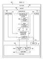
- FIG. 1 an illustration of a block diagram of an aircraft is depicted in accordance with an illustrative embodiment.
- electric power for aircraft 100 is provided by power system 102.
- Aircraft 100 may be any type of aircraft.
- aircraft 100 may include a fixed wing, rotary wing, or lighter than air aircraft.
- Aircraft 100 may be configured for carrying passengers, cargo, both passengers and cargo, or may be used for performing any other operation or mission.
- Aircraft 100 may be operated by an airline, a military unit, or any other private or governmental entity.
- Aircraft 100 is an example of platform 104 in which illustrative embodiments may be implemented.
- Arc fault protection in accordance with an illustrative embodiment, may be provided for power system 102 on or for any type of platform 104 other than aircraft 100.
- platform 104 may be any vehicle that is configured for traveling through the air, in space, on land, on the surface of water, underwater, or in any other operating environment or combination of environments.
- Arc fault protection in accordance with an illustrative embodiment, may be provided for power system 102 on or for any type of platform 104 other than a vehicle.
- platform 104 may include any fixed or movable structure that may be provided with electrical power by power system 102.
- Power system 102 includes generators 106 and power distribution and conversion systems 108.
- generators 106 may be driven by operation of the engines of aircraft 100.
- generators 106 may generate variable frequency three-phase AC power.
- Feeder lines 110 carry the generated AC power from generators 106 to power distribution and conversion systems 108.
- Power distribution and conversion systems 108 may include power conversion systems 109 and power distribution systems 111.
- Power conversion systems 109 may include devices and systems that are configured to convert the AC power provided by generators 106 on feeder lines 110 to electrical power for loads 112 and 114.
- power conversion systems 109 may include rectifiers, transformers, rectifiers and transformers, other electrical power conversion devices or systems, or any combination of electrical power conversion devices or systems.
- Rectifiers may be used to provide DC power from the AC power provided by generators 106.
- Transformers may be used to provide various levels of AC power. Transformers in combination with rectifiers may be used to provide various levels of DC power.
- Power distribution systems 111 may include structures for distributing the electrical power to loads 112 and 114. Power distribution systems 111 also may include a number of AC buses, a number of DC buses, or a number of AC buses and DC buses. Feeder lines may be provided for carrying power between the buses in power distribution and conversion systems 108 and between the buses in power distribution and conversion systems 108 and loads 112 and 114. For example, feeder lines 116 and 118 may carry power from power distribution and conversion systems 108 to loads 112 and 114, respectively.
- Loads 112 and 114 may include any electrical device or system on aircraft 100 that uses electrical power. Loads 112 may be part of power system 102. Loads 114 may be part of aircraft 100, or located in or on aircraft 100, but not part of power system 102.
- safe operation of power system 102 in the event of undesired conditions in power system 102 is provided by power system protection controller 120.
- undesired conditions in power system 102 may include arc faults, other undesired conditions, or combinations of undesired conditions. Safe operation is timely removal of an undesired condition.
- power system protection controller 120 is configured to identify undesired conditions in power system 102 and to control power system 102 in an appropriate manner in response to identifying undesired conditions in power system 102.
- power system protection controller 120 may be connected to generators 106, power distribution and conversion systems 108, and feeder lines 110, 116, and 118 by appropriate sensors in order to identify undesired conditions in generators 106, power distribution and conversion systems 108, and feeder lines 110, 116, and 118.
- Power system protection controller 120 may be connected to appropriate devices in generators 106 and power distribution and conversion systems 108 in order to control power system 102 in an appropriate manner in response to identifying undesired conditions in power system 102.
- power system protection controller 120 may be connected to generators 106 in an appropriate manner so that power system protection controller 120 may turn off generators 106 in response to identifying selected undesired conditions in power system 102.
- Power system protection controller 120 may be connected to circuit breakers, contactors, or other devices in power distribution and conversion systems 108 in an appropriate manner so that power system protection controller 120 may disconnect or isolate portions of power system 102 in response to identifying selected undesired conditions in power system 102.
- power system protection controller 120 may be implemented by generator controller 122.
- Generator controller 122 may be configured for controlling operation of one or more of generators 106.
- Generator controller 122 also may be configured to perform a number of functions of power system protection controller 120 to protect generators 106 and other components in power system 102 when undesired conditions are identified in power system 102.
- power system protection controller 120 may be implemented in a number of devices or systems that are separate from generator controller 122.
- the functions of power system protection controller 120 as described herein may be implemented by a number of devices or systems that may be distributed at various locations in power system 102.
- Aircraft 100 also may include flight deck 124.
- Flight deck 124 also may be referred to as the cockpit of aircraft 100.
- Flight deck 124 may include various controls which enable flight crew 126 to control the operation of aircraft 100.
- flight deck 124 may include an area located near the front of aircraft 100.
- flight crew 126 may include a pilot, a co-pilot, a navigator, other personnel, or various combinations of personnel for controlling the operation of aircraft 100.
- Flight deck 124 may include a number of devices or systems for presenting various types of information for use by flight crew 126.
- flight deck 124 may include flight deck display 128.
- Flight deck display 128 may be configured to indicate to flight crew 126 a status of power system 102 and of any actions taken by power system protection controller 120 to protect power system 102 in response to undesired conditions in power system 102.
- flight deck display 128 may be configured to provide an indication to flight crew 126 when generators 106 are turned off by power system protection controller 120 in response to undesired conditions in power system 102.
- fault reset switch 130 may be provided on flight deck 124 for use by flight crew 126.
- power system protection controller 120 may attempt to undo selected actions taken by power system protection controller 120 to protect power system 102 in response to undesired conditions in power system 102.
- flight deck display 128 may indicate to flight crew 126 that generators 106 have been turned off in response to undesired conditions in power system 102. In this case, flight crew 126 may attempt to restart generators 106 by actuating fault reset switch 130.
- Fault reset switch 130 may be implemented as a physical switch, button, or other physical device that may be actuated by flight crew 126.
- fault reset switch 130 may be a virtual switch, button, or other user interface that may be part of a graphical user interface that is presented to flight crew 126 on flight deck 124.
- fault reset switch 130 may be provided as part of a graphical user interface that also includes flight deck display 128.
- flight deck 124 on aircraft 100 The location of flight deck 124 on aircraft 100, the composition of flight crew 126, the number and types of devices and systems used to implement displays on flight deck 124, and the types of information presented to flight crew 126 on such displays may depend on various factors including, for example, without limitation, the type of aircraft 100, the operations to be performed by aircraft 100, specific flight or mission requirements, or other factors or various combinations of factors.
- the display of power system protection information that is presented on flight deck display 128 in an aircraft and fault reset switch 130 may be provided in one or more areas or locations on platform 104, or connected to platform 104, where operations for monitoring and control of power system 102 may be performed.
- the display of power system protection information and fault reset switch 130 may be provided in a control room or one or more other local or remote locations or combinations of locations from which a human operator may monitor and control power system 102 using the display of power system protection information and fault reset switch 130.
- illustrative embodiments may include monitoring and controlling power system 102 using a display of power system protection information and fault reset switch 130 from an area that may not be referred to as a flight deck or a cockpit and by operators that may not be referred to as flight crew.
- power system 200 is an example of one implementation of power system 102 in Figure 1 .
- Power system 200 includes generator 202.
- generator 202 may be driven by an engine on an aircraft.
- generator 202 may generate variable frequency three-phase AC power.
- Generator feeder lines 204 carry the generated AC power from generator 202 to high voltage AC bus 206.
- Generator circuit breaker 207 may be provided on generator feeder lines 204.
- Generator circuit breaker 207 may be any device that is configured to disconnect high voltage AC bus 206 from generator 202 when generator circuit breaker 207 is opened.
- High voltage AC bus 206 is configured to distribute the relatively high voltage AC power provided by generator 202 to various loads.
- high voltage AC bus 206 may be configured to distribute the relatively high voltage AC power provided by generator 202 to rectifier 208, load 210, and transformer 212.
- Contactor 209 may be provided on load feeder line 239 connecting high voltage AC bus 206 to rectifier 208.
- Contactor 211 may be provided on load feeder line 224 connecting high voltage AC bus 206 to load 210.
- Contactor 213 may be provided on load feeder line 241 connecting high voltage AC bus 206 to transformer 212.
- Tie bus contactor 270 may be provided between high voltage AC bus 206 and high voltage AC bus 272.
- high voltage AC bus 272 may be an adjacent or other AC bus that receives power from another generator 274 on the aircraft.
- tie bus contactor 270 may be closed after generator circuit breaker 207 is opened. Closing tie bus contactor 270 restores power to high voltage AC bus 206, and thus to all of the loads supported by high voltage AC bus 206, from high voltage AC bus 272.
- Voltage sensor 276 may be configured to identify the voltage on high voltage AC bus 272.
- Rectifier 208 is configured to convert the AC power provided by high voltage AC bus 206 to DC power. Rectifier 208 may be any AC to DC power converter. DC power from rectifier 208 may be provided on DC bus 214.
- DC loads may be powered by the DC power on DC bus 214.
- DC loads may include motor controller 216, motor 218, motor controller 220, and motor 222.
- DC loads connected to DC bus 214 may include a single motor and motor controller or more than two motors and motor controllers.
- the DC loads connected to DC bus 214 may additionally or alternatively comprise a number of DC loads other than motors and motor controllers.
- Motors 218 and 222 may be any type of electric motor.
- motors 218 and 222 may be induction motors, permanent magnet motors, synchronous motors with independent excitation, or any other type of electric motor.
- Motors 218 and 222 may be the same or different types of motors.
- Motor controllers 216 and 220 may be any type of motor controllers that are appropriate for controlling motors 218 and 222, respectively. Depending on the type of motor to be controlled, motor controllers 216 and 220 may be of any appropriate size and complexity. In one example, motor controller 216, motor controller 220, or both may be solid state multifunctional motor controllers that provide power conversion for driving motor 218 or motor 222, respectively. A motor controller of this type may be used to drive various types of motors and motor loads.
- Contactor 219 may be provided on load feeder lines 243 connecting DC bus 214 to motor controller 216 and motor 218. Contactor 219 may be configured to disconnect motor controller 216 and motor 218 from DC bus 214 when contactor 219 is opened.
- Contactor 223 may be provided on load feeder lines 245 connecting DC bus 214 to motor controller 220 and motor 222. Contactor 223 may be configured to disconnect motor controller 220 and motor 222 from DC bus 214 when contactor 223 is opened.
- Load 210 may be any number AC loads.
- Load feeder lines 224 may carry AC power from high voltage AC bus 206 to load 210.
- Load 210 may include motors, motor controllers, or other AC loads or combinations of AC load.
- transformer 212 is configured to convert the relatively high voltage AC power on high voltage AC bus 206 to lower voltage AC power.
- the lower voltage AC power may be provided from transformer 212 to low voltage AC bus 226.
- AC power may be distributed from low voltage AC bus 226 to loads 228.
- Loads 228 may be any number of AC loads.
- loads 228 may include single phase AC loads, three phase AC loads, or both.
- Contactor 229 may be provided on load feeder lines 247 connecting low voltage AC bus 226 to transformer 212. Contactor 229 may be configured to disconnect low voltage AC bus 226 from transformer 212 when contactor 229 is opened.
- current sensor 230 may be configured to identify the current at a first point on generator feeder lines 204.
- the first point on generator feeder lines 204 may be a location on generator feeder lines 204 that is at or near generator 202.
- Current sensor 232 may be configured to identify the current at a second point on generator feeder lines 204.
- the second point on generator feeder lines 204 may be a location on generator feeder lines 204 that is at or near high voltage AC bus 206.
- a differential current on generator feeder lines 204 may be identified.
- a differential current on generator feeder lines 204 may indicate an arc fault or other undesired condition on generator feeder lines 204.
- current sensor 234 may be configured to identify the current at a first point on load feeder lines 224.
- the first point on load feeder lines 224 may be a location on load feeder lines 224 that is at or near high voltage AC bus 206.
- Current sensor 236 may be configured to identify the current at a second point on load feeder lines 224.
- the second point on load feeder lines 224 may be a location on load feeder lines 224 that is at or near load 210.
- Voltage sensor 237 may be configured to identify the voltage on high voltage AC bus 206.
- Current sensor 238 may be configured to identify the current on load feeder lines 239 connecting high voltage AC bus 206 to rectifier 208.
- Current sensor 240 may be configured to identify the current on load feeder lines 241 connecting high voltage AC bus 206 to transformer 212.
- Voltage sensor 280 may be configured to identify the voltage on DC bus 214.
- Current sensor 242 may be configured to identify the current on load feeder lines 243 connecting DC bus 214 to motor controller 216. Alternatively, or in addition, current sensor 242 may be configured to identify the current between motor controller 216 and motor 218.
- Current sensor 244 may be configured to identify the current on load feeder lines 245 connecting DC bus 214 to motor controller 220.
- current sensor 244 may be configured to identify the current between motor controller 220 and motor 222.
- Current sensor 246 may be configured to identify the current on load feeder lines 247 connecting transformer 212 to low voltage AC bus 226.
- Voltage sensor 282 may be configured to identify the voltage on low voltage AC bus 226.
- high voltage AC bus 206, generator circuit breaker 207, contactor 209, contactor 211, contactor 213, current sensor 234, voltage sensor 237, current sensor 238, and current sensor 240 may be included in high voltage AC power panel 248.
- DC bus 214, contactor 219, contactor 223, current sensor 242, and current sensor 244 may be included in DC power panel 250.
- Low voltage AC bus 226, contactor 229, and current sensor 246 may be included in low voltage AC power panel 252.
- Power system protection controller 254 may be connected to the various current and voltage sensors in power system 200. Power system protection controller 254 may be configured to identify various undesired conditions in power system 200 from the data provided by these sensors. Power system protection controller 254 also may be connected to generator 202, generator circuit breaker 207, and the various contactors in power system 200. Power system protection controller 254 may be configured to trip generator 202, open generator circuit breaker 207, and open the various contactors in power system 200 as appropriate to protect power system 200 when an undesired condition is identified in power system 200. Power system protection controller 254 also may be configured to close tie bus contactor 270 after generator circuit breaker 207 is opened, thereby restoring power to high voltage AC bus 206 from high voltage AC bus 272.
- Manual fault reset 256 also may be provided to power system protection controller 254.
- Manual fault reset 256 may comprise a signal that is provided to system protection controller to indicate that a manual reset of a fault in power system 200 was initiated.
- manual fault reset 256 may be initiated by a member of the flight crew actuating a fault reset switch provided on the flight deck of an aircraft.
- power system protection controller 254 may be implemented by generator controller 260.
- Generator controller 260 may be configured for controlling operation of generator 202.
- Generator controller 260 also may be configured to perform a number of functions of power system protection controller 254 to protect generator 202 and other components in power system 200 when undesired conditions are identified in power system 200.
- power system protection controller 254 may be implemented in a number of devices or systems that are separate from generator controller 260.
- the functions of power system protection controller 254 as described herein may be implemented by a number of devices or systems that may be distributed at various locations in power system 200.
- Figure 1 and Figure 2 are not meant to imply physical or architectural limitations to the manner in which different illustrative embodiments may be implemented.
- Other components in addition to, in place of, or both in addition to and in place of the ones illustrated may be used. Some components may be unnecessary in some illustrative embodiments.
- the blocks are presented to illustrate some functional components. One or more of these blocks may be combined or divided into different blocks when implemented in different illustrative embodiments.
- power system protection controller 120 in Figure 1 or by power system protection controller 254 in Figure 2 may be implemented in a centralized manner at one location in a power system or may be implemented in a distributed manner at various locations in a power system. Some or all of the functions performed by power system protection controller 120 or power system protection controller 254 may be implemented along with other control functions performed at various locations in the power system. For example, without limitation, some or all of the functions performed by power system protection controller 120 may be implemented as part of generator controller 122 in Figure 1 . Some or all of the functions performed by power system protection controller 254 may be implemented as part of generator controller 260 in Figure 2 .
- power system protection controller 120 or by power system protection controller 254 as described herein may be implemented in hardware or in hardware and software.
- power system protection controller 120 or power system protection controller 254 may include a programmable processor unit for running the software to perform the functions.
- the processor unit may be a microprocessor, other processor unit, or a combination of processor units.
- Such a processor unit may be provided in either a general or special purpose computer or other computing device.
- the processor unit may serve to run instructions for software that may be loaded into memory, persistent storage, or both.
- the processor unit may be a number of processors, a multi-processor core, or some other type of processor, depending on the particular implementation. Further, the processor unit may be implemented using a number of heterogeneous processor systems in which a main processor is present with secondary processors on a single chip. As another illustrative example, the processor unit may be a symmetric multi-processor system containing multiple processors of the same type.
- the processes of the different embodiments may be performed by the processor unit using software in the form of computer-implemented instructions.
- Instructions for controlling the processor unit to perform the desired functions in accordance with illustrative embodiments may be located in storage devices which are in communication with the processor unit.
- the instructions may be in a functional form on persistent storage. These instructions may be loaded into memory for execution by the processor unit.
- These instructions may be referred to as program instructions, program code, computer usable program code, or computer readable program code that may be read and executed by the processor unit.
- the program code in the different embodiments may be embodied on different physical or computer readable storage media, such as memory or persistent storage.
- power system protection controller 120 or of power system protection controller 254 may be implemented in a hardware unit that has circuits that are manufactured or configured for a particular use. This type of hardware may perform operations without needing program code to be loaded into a memory from a storage device to be configured to perform the operations.
- such a hardware unit may be a circuit system, an application specific integrated circuit (ASIC), a programmable logic device, or some other suitable type of hardware configured to perform a number of operations.
- ASIC application specific integrated circuit
- a programmable logic device the device is configured to perform the number of operations.
- the device may be reconfigured at a later time or may be permanently configured to perform the number of operations.
- programmable logic devices include, for example, a programmable logic array, a programmable array logic, a field programmable logic array, a field programmable gate array, and other suitable hardware devices.
- program code may be omitted, because the processes for the different embodiments are implemented in a hardware unit.
- power system protection controller 120 or by power system protection controller 254 may be implemented using a combination of processors found in computers and hardware units.
- Power system protection controller 120 or power system protection controller 254 may include a number of hardware units and a number of processors that are configured to perform the desired functions.
- some of the functionality provided by power system protection controller 120 or by power system protection controller 254 may be implemented in the number of hardware units while other processes may be implemented in the number of processors.
- power system protection controller 120 or by power system protection controller 254 may be implemented using discrete circuit components, either alone or in combination with hardware units, processor units, or both.
- power system protection control logic 300 is an example of one implementation of power system protection control logic that may be implemented in power system protection controller 120 to protect power system 102 in Figure 1 or in power system protection controller 254 to protect power system 200 in Figure 2 .
- Generator feeder differential current condition 302 may be identified when different current levels are detected at two points on the generator feeder lines providing power from the generator. For example, without limitation, generator feeder differential current condition 302 may be identified by comparing current measured at the generator with current measured at an input to the main distribution point in the power system. Generator feeder differential current condition 302 is identified if there is a difference in the current levels measured at these two points.
- time delay 304 may be on the order of approximately tens of milliseconds or another appropriate time period.
- Over voltage transient protection condition 308 may be identified by measuring the voltage level at a distribution point in the power system. Over voltage transient protection condition 308 may be identified when voltage at the distribution point rises above a threshold voltage level as a result of loads being removed from the distribution point.
- time delay 310 may be on the order of approximately milliseconds or some other appropriate time period.
- the generator and high voltage AC bus may be automatically reset when operation 312 is implemented in response to over voltage transient protection condition 308. However, this automatic reset may be disabled after the generator is tripped for the second time (operation 314) in response to over voltage transient protection condition 308.
- Instant trip generator condition 316 may result from internal generator inconsistencies or inconsistencies in the generator that may affect voltage regulation or that may affect the generator controller in undesired ways.
- the generator may be tripped (operation 306) in response to identifying instant trip generator condition 316 for more than time delay 318.
- time delay 318 may be on the order of approximately milliseconds or another appropriate time period.
- the generator may be tripped and the high voltage AC bus isolated (operation 312) in response to identifying generator overcurrent greater than arcing threshold 320 for more than time delay 322.
- arcing threshold may be on the order of approximately hundreds of amps or another appropriate current threshold level.
- time delay 322 may be on the order of hundreds of milliseconds or another appropriate time period.
- time delay 322 may be selected from shorter time delay 323 or longer time delay 325. Shorter time delay 323 may be used (operation 326) in response to manual fault reset 324. Otherwise, longer time delay 325 may be used. For example, without limitation, longer time delay 325 may be approximately a number of times longer than shorter time delay 323.
- the generator may not be tripped in response to identifying instant trip generator condition 316 if generator over current greater than arcing threshold 320 is identified, as indicated by AND operation 328.
- the generator may be tripped and the high voltage AC bus may be isolated in response to identifying generator over current greater than overload threshold 330 for more than time delay 332.
- the overload threshold may be less than the arcing threshold used to identify generator over current greater than arcing threshold 320.
- time delay 332 may be on the order of seconds or another appropriate time period. In any case, time delay 332 may be greater than time delay 322.
- the generator may be tripped and the high voltage AC bus isolated (operation 312) in response to identifying generator DC content condition 334 for more than time delay 336.
- Generator DC content condition 334 may be identified by identifying the presence of DC content on the AC bus provided by the generator.
- time delay 336 may be on the order of hundreds of milliseconds or another appropriate time period. In any case, time delay 336 may be greater than time delay 322.
- a fault in the power system may be cleared downstream of the high voltage AC bus (operation 342).
- time delay 340 may be on the order of approximately tens of milliseconds or another appropriate time period.
- a fault in the power system may be cleared downstream from the high voltage AC bus (operation 342) in response to identifying ground fault condition 344 for more than time delay 346.
- time delay 346 may be on the order of approximately milliseconds or another appropriate time period.
- distribution feeder differential current condition 338 and ground fault condition 344 are examples of other undesired conditions 348.
- Other undesired conditions 348 are undesired conditions in the power system that occur or are detected downstream from the high voltage AC bus in the power system.
- Different threshold levels may be used to determine when a fault condition is identified, thereby starting a time delay, and for determining whether the fault condition persists for more than the time delay, to provide hysteresis in the fault condition protections described above.
- a current exceeding a first threshold level may indicate an arc fault or an overload condition, thereby starting a time delay counter or other device or function for timing a selected time delay period.
- the current may be required to drop below a second threshold level, that is lower than the first threshold level, before the fault condition is identified as cleared, thereby interrupting the time delay before any further action is taken.
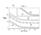
- curves 400 illustrate time delays with respect to current levels for responding to various undesired conditions in a power system.
- curves 400 may be used by power system protection controller 120 in Figure 1 or power system protection controller 254 in Figure 2 .
- curves 402 are for conventional generator overcurrent conditions.
- Curves 404 are for arc fault overcurrent conditions.
- Curves 406 are for overcurrent conditions in a tie bus in the power system.
- Curves 408 are for overcurrent conditions in a distribution bus in the power system.
- Curves 410 are for controlling a circuit breaker for a load in the power system. Curves 402, 404, 406, 408, and 410 should not overlap in any region to preserve proper coordination and minimize the impact on loads.
- each of curves 402, 404, 406, 408, and 410 includes two lines that define a band region.
- This band region reflects allowed variability in the time delay that may be implemented by various devices that may be used to trigger a response to various undesired conditions in the power system. For example, for a given current level, a contactor or circuit breaker may be opened, or other appropriate action taken, any time after a time delay that is indicated by the left of the two lines in the curve and before a time delay that is indicated by the right of the two lines in the curve.
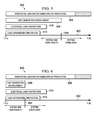
- FIG. 5 an illustration of fault protection clearing times is depicted in accordance with an illustrative embodiment.
- relative fault protection clearing times 500 are shown with respect to time scale 502.
- Line 504 on time scale 502 indicates an approximate division of time scale 502 between arcing and hard faults and system overloads.
- relative clearing times for traditional generator overcurrent protection 506, fast generator overcurrent 508, electrical load contactors 510, and load differential protection 512 are shown.
- FIG. 6 an illustration of fault protection clearing times following a manual reset action is depicted in accordance with an illustrative embodiment.
- relative fault protection clearing times 600 are shown with respect to time scale 602.
- Line 604 on time scale 602 indicates an approximate division of time scale 602 between arcing and hard faults and system overloads.
- relative clearing times for traditional generator overcurrent protection 606, fast generator overcurrent 608, electrical load contactors 610, and load differential protection 612 are shown. Note that in this example, fault protection clearing times for fast generator overcurrent 608 are shorter following a manual reset action than fast generator overcurrent clearing times 508 in Figure 5 .
- the different illustrative embodiments thereby provide for safe operation of the power system on an aircraft in the event of undesired conditions in the power system, such as arc faults and other undesired conditions.
- Power system protection in accordance with illustrative embodiments is robust.
- normal transients in the power system may not result in false indications of undesired conditions. Therefore, such normal transients may not cause power system protection in accordance with the illustrative embodiments to interrupt power to the loads being powered by the power system.
- Power system protection in accordance with the illustrative embodiments also is coordinated. This coordination ensures that only the area of the power system containing the cause of the undesired condition is isolated from the rest of the power system. Therefore, the number of loads affected by the response to the undesired condition is minimized and the number of available power sources is maximized.
- each block in the flowcharts or block diagrams may represent a module, segment, function, or a portion of an operation or step.
- the function or functions noted in the blocks may occur out of the order noted in the figures. For example, in some cases, two blocks shown in succession may be executed substantially concurrently, or the blocks may sometimes be executed in the reverse order, depending upon the functionality involved.
Landscapes
- Engineering & Computer Science (AREA)
- Power Engineering (AREA)
- Supply And Distribution Of Alternating Current (AREA)
- Emergency Protection Circuit Devices (AREA)
- Protection Of Generators And Motors (AREA)
Applications Claiming Priority (1)
| Application Number | Priority Date | Filing Date | Title |
|---|---|---|---|
| US13/455,954 US8861147B2 (en) | 2012-04-25 | 2012-04-25 | Fault protection for aircraft power systems |
Publications (3)
| Publication Number | Publication Date |
|---|---|
| EP2658062A2 true EP2658062A2 (de) | 2013-10-30 |
| EP2658062A3 EP2658062A3 (de) | 2015-08-05 |
| EP2658062B1 EP2658062B1 (de) | 2018-08-01 |
Family
ID=48143082
Family Applications (1)
| Application Number | Title | Priority Date | Filing Date |
|---|---|---|---|
| EP13163197.0A Active EP2658062B1 (de) | 2012-04-25 | 2013-04-10 | Fehlerschutz für Flugzeugstromversorgungssysteme |
Country Status (2)
| Country | Link |
|---|---|
| US (1) | US8861147B2 (de) |
| EP (1) | EP2658062B1 (de) |
Cited By (2)
| Publication number | Priority date | Publication date | Assignee | Title |
|---|---|---|---|---|
| EP4024696A1 (de) * | 2021-01-04 | 2022-07-06 | Hamilton Sundstrand Corporation | Schnelle por-trimmkorrektur |
| WO2023174706A1 (de) * | 2022-03-17 | 2023-09-21 | Siemens Aktiengesellschaft | Verfahren zum störlichtbogenschutz |
Families Citing this family (10)
| Publication number | Priority date | Publication date | Assignee | Title |
|---|---|---|---|---|
| US9407083B1 (en) | 2012-04-26 | 2016-08-02 | The Boeing Company | Combined subtransient current suppression and overvoltage transient protection |
| US9646114B2 (en) * | 2013-07-10 | 2017-05-09 | The Boeing Company | Electrical power system stability |
| CN109075556B (zh) | 2016-04-28 | 2019-12-03 | 罗姆股份有限公司 | 过电流保护电路 |
| US10403866B2 (en) | 2016-07-28 | 2019-09-03 | Goal Zero Llc | Energy storage and power supply system with reserve mode and override |
| US10965125B2 (en) * | 2018-07-11 | 2021-03-30 | The Boeing Company | Simultaneous bidirectional power usage of generator power feeders |
| US10763659B2 (en) * | 2019-01-29 | 2020-09-01 | Arc Suppression Technologies | Power contact fault clearing device |
| US11300600B2 (en) * | 2020-03-18 | 2022-04-12 | Hamilton Sundstrand Corporation | Arc zone fault detection |
| US11814158B1 (en) * | 2022-04-28 | 2023-11-14 | Beta Air, Llc | Systems and methods for determining areas of discrepancy in flight for an electric aircraft |
| US11705719B1 (en) | 2022-05-10 | 2023-07-18 | Hamilton Sundstrand Corporation | Fast disconnects for generator systems |
| US20250110167A1 (en) * | 2023-09-28 | 2025-04-03 | Ge Aviation Systems Limited | Fault detection system and power distribution system having same |
Family Cites Families (16)
| Publication number | Priority date | Publication date | Assignee | Title |
|---|---|---|---|---|
| US3634729A (en) * | 1970-05-07 | 1972-01-11 | Westinghouse Electric Corp | Circuit breaker including improved overcurrent protective device |
| US4149210A (en) * | 1977-09-09 | 1979-04-10 | Westinghouse Electric Corp. | Electrical apparatus including interlocking circuit for short-time delay and long-time delay tripping |
| US4973902A (en) | 1989-12-11 | 1990-11-27 | Sundstrand Corporation | Fault detector for aircraft variable speed, constant frequency power supply |
| US5805394A (en) * | 1997-06-17 | 1998-09-08 | Sundstrand Corporation | Overvoltage protection circuit for a generating system utilizing a fault current sensing Circuit in combination with a shunting circuit |
| US6088205A (en) * | 1997-12-19 | 2000-07-11 | Leviton Manufacturing Co., Inc. | Arc fault detector with circuit interrupter |
| US6625550B1 (en) | 1998-02-19 | 2003-09-23 | Square D Company | Arc fault detection for aircraft |
| US7253640B2 (en) | 2003-01-13 | 2007-08-07 | Eaton Corporation | Arc fault detector and method for locating an arc fault |
| US7489138B2 (en) | 2006-11-30 | 2009-02-10 | Honeywell International Inc. | Differential arc fault detection |
| US7646572B2 (en) | 2006-12-04 | 2010-01-12 | Eaton Corporation | Aircraft system and method of arc fault protection for an aircraft system |
| US7564662B2 (en) | 2007-02-28 | 2009-07-21 | Caterpillar Inc. | Overload protection system for an electromagnetic lift |
| KR100961171B1 (ko) * | 2008-09-23 | 2010-06-09 | 한국전력공사 | 발전기 비동기투입 보호 장치 |
| US8233254B2 (en) | 2009-04-10 | 2012-07-31 | Honeywell International, Inc. | Method of ensuring the coordinated arc fault protection in a heirarchial power distribution system |
| US8203815B2 (en) | 2009-05-08 | 2012-06-19 | Hamilton Sundstrand Corporation | System and method to provide transient overvoltage suppression |
| US8406021B2 (en) | 2009-08-10 | 2013-03-26 | Emerson Climate Technologies, Inc. | System and method for reducing line current distortion |
| US8154154B2 (en) | 2009-08-11 | 2012-04-10 | Leviton Manufacturing Co., Inc. | Automatic switch configuration |
| US20130286513A1 (en) | 2012-04-26 | 2013-10-31 | The Boeing Company | Subtransient Current Suppression |
-
2012
- 2012-04-25 US US13/455,954 patent/US8861147B2/en active Active
-
2013
- 2013-04-10 EP EP13163197.0A patent/EP2658062B1/de active Active
Non-Patent Citations (1)
| Title |
|---|
| None |
Cited By (4)
| Publication number | Priority date | Publication date | Assignee | Title |
|---|---|---|---|---|
| EP4024696A1 (de) * | 2021-01-04 | 2022-07-06 | Hamilton Sundstrand Corporation | Schnelle por-trimmkorrektur |
| US12034396B2 (en) | 2021-01-04 | 2024-07-09 | Hamilton Sundstrand Corporation | Fast POR trim correction |
| EP4383493A3 (de) * | 2021-01-04 | 2024-09-04 | Hamilton Sundstrand Corporation | Schnelle por-trimmkorrektur |
| WO2023174706A1 (de) * | 2022-03-17 | 2023-09-21 | Siemens Aktiengesellschaft | Verfahren zum störlichtbogenschutz |
Also Published As
| Publication number | Publication date |
|---|---|
| EP2658062B1 (de) | 2018-08-01 |
| US8861147B2 (en) | 2014-10-14 |
| US20130286515A1 (en) | 2013-10-31 |
| EP2658062A3 (de) | 2015-08-05 |
Similar Documents
| Publication | Publication Date | Title |
|---|---|---|
| US8861147B2 (en) | Fault protection for aircraft power systems | |
| EP2424059B1 (de) | Verfahren, Systeme und Vorrichtung zur Erkennung von Lichtbogenereignissen mit Strom und Spannung | |
| CN106443301B (zh) | 双极高压直流接地故障检测的系统、方法和装置 | |
| EP3041101B1 (de) | System zur verbesserung der blitzimmunität für einen festkörperleistungsregler | |
| CA2803400C (en) | Subtransient current suppression | |
| RU157512U1 (ru) | КОМПЛЕКТНОЕ КОМБИНИРОВАННОЕ УСТРОЙСТВО РЕЛЕЙНОЙ ЗАЩИТЫ И АВТОМАТИКИ НА ПЕРЕМЕННОМ ОПЕРАТИВНОМ ТОКЕ ДЛЯ ПРИСОЕДИНЕНИЙ РАСПРЕДЕЛИТЕЛЬНОГО УСТРОЙСТВА ЭЛЕКТРИЧЕСКИХ СЕТЕЙ 6-35 кВ | |
| JPH1051949A (ja) | 受電保護装置 | |
| EP2650996B1 (de) | Überstromschutz und Fehlerisolierung | |
| EP2654154A2 (de) | Leistungsverwaltung und -verteilungssystem mit Fehlererkennung und Isolierungsanordnung und Verfahren | |
| EP3883104A1 (de) | Stromqualitätsschutz für transformatorgleichrichtereinheit | |
| EP2860837B1 (de) | Virtueller Schutzschalter | |
| US20080129112A1 (en) | Aircraft system and method of arc fault protection for an aircraft system | |
| EP2651026B1 (de) | Automatische Fehlerisolierungsmethodologie | |
| RU2513032C1 (ru) | Способ защиты ячеек комплексных распределительных устройств от дуговых замыканий | |
| RU2311699C2 (ru) | Способ защиты электрораспределительных сетей от дуговых коротких замыканий и устройство для его осуществления | |
| US20060109600A1 (en) | Permanent three-pole independent pole operation recloser simulator feature in a single-pole trip capable recloser control | |
| US11165239B2 (en) | Virtual electronic circuit breaker | |
| JP2012061968A (ja) | 航空機用静止型電源装置ユニット | |
| RU2611059C2 (ru) | Способ измерения для обнаружения повреждения трехфазной сети | |
| JP2010183745A (ja) | 短絡保護装置 | |
| EP3319193A1 (de) | Virtueller elektronischer schutzschalter | |
| Jiang et al. | Research on pilot protection applied in aircraft annular power distribution system | |
| CN109066590A (zh) | 一种接地保护电路及电机供电系统 | |
| JP2015139228A (ja) | 地絡検出装置 |
Legal Events
| Date | Code | Title | Description |
|---|---|---|---|
| PUAI | Public reference made under article 153(3) epc to a published international application that has entered the european phase |
Free format text: ORIGINAL CODE: 0009012 |
|
| AK | Designated contracting states |
Kind code of ref document: A2 Designated state(s): AL AT BE BG CH CY CZ DE DK EE ES FI FR GB GR HR HU IE IS IT LI LT LU LV MC MK MT NL NO PL PT RO RS SE SI SK SM TR |
|
| AX | Request for extension of the european patent |
Extension state: BA ME |
|
| RIN1 | Information on inventor provided before grant (corrected) |
Inventor name: KARIMI, KAMIAR J. Inventor name: MATHESON, EVELYN M. Inventor name: WHITE, JEFFREY JOSEPH |
|
| PUAL | Search report despatched |
Free format text: ORIGINAL CODE: 0009013 |
|
| AK | Designated contracting states |
Kind code of ref document: A3 Designated state(s): AL AT BE BG CH CY CZ DE DK EE ES FI FR GB GR HR HU IE IS IT LI LT LU LV MC MK MT NL NO PL PT RO RS SE SI SK SM TR |
|
| AX | Request for extension of the european patent |
Extension state: BA ME |
|
| RIC1 | Information provided on ipc code assigned before grant |
Ipc: H02H 3/30 20060101ALN20150626BHEP Ipc: H02H 7/26 20060101ALN20150626BHEP Ipc: H02H 3/00 20060101ALI20150626BHEP Ipc: H02H 3/093 20060101AFI20150626BHEP Ipc: H02H 7/06 20060101ALI20150626BHEP |
|
| 17P | Request for examination filed |
Effective date: 20160205 |
|
| RBV | Designated contracting states (corrected) |
Designated state(s): AL AT BE BG CH CY CZ DE DK EE ES FI FR GB GR HR HU IE IS IT LI LT LU LV MC MK MT NL NO PL PT RO RS SE SI SK SM TR |
|
| GRAP | Despatch of communication of intention to grant a patent |
Free format text: ORIGINAL CODE: EPIDOSNIGR1 |
|
| STAA | Information on the status of an ep patent application or granted ep patent |
Free format text: STATUS: GRANT OF PATENT IS INTENDED |
|
| RIC1 | Information provided on ipc code assigned before grant |
Ipc: H02H 7/06 20060101ALI20180122BHEP Ipc: H02H 7/26 20060101ALN20180122BHEP Ipc: H02H 3/30 20060101ALN20180122BHEP Ipc: H02H 3/093 20060101AFI20180122BHEP Ipc: H02H 3/00 20060101ALI20180122BHEP |
|
| INTG | Intention to grant announced |
Effective date: 20180213 |
|
| GRAS | Grant fee paid |
Free format text: ORIGINAL CODE: EPIDOSNIGR3 |
|
| GRAA | (expected) grant |
Free format text: ORIGINAL CODE: 0009210 |
|
| STAA | Information on the status of an ep patent application or granted ep patent |
Free format text: STATUS: THE PATENT HAS BEEN GRANTED |
|
| AK | Designated contracting states |
Kind code of ref document: B1 Designated state(s): AL AT BE BG CH CY CZ DE DK EE ES FI FR GB GR HR HU IE IS IT LI LT LU LV MC MK MT NL NO PL PT RO RS SE SI SK SM TR |
|
| REG | Reference to a national code |
Ref country code: GB Ref legal event code: FG4D |
|
| REG | Reference to a national code |
Ref country code: CH Ref legal event code: EP Ref country code: AT Ref legal event code: REF Ref document number: 1025457 Country of ref document: AT Kind code of ref document: T Effective date: 20180815 |
|
| REG | Reference to a national code |
Ref country code: IE Ref legal event code: FG4D |
|
| REG | Reference to a national code |
Ref country code: DE Ref legal event code: R096 Ref document number: 602013041062 Country of ref document: DE |
|
| REG | Reference to a national code |
Ref country code: NL Ref legal event code: MP Effective date: 20180801 |
|
| REG | Reference to a national code |
Ref country code: LT Ref legal event code: MG4D |
|
| REG | Reference to a national code |
Ref country code: AT Ref legal event code: MK05 Ref document number: 1025457 Country of ref document: AT Kind code of ref document: T Effective date: 20180801 |
|
| PG25 | Lapsed in a contracting state [announced via postgrant information from national office to epo] |
Ref country code: IS Free format text: LAPSE BECAUSE OF FAILURE TO SUBMIT A TRANSLATION OF THE DESCRIPTION OR TO PAY THE FEE WITHIN THE PRESCRIBED TIME-LIMIT Effective date: 20181201 Ref country code: NL Free format text: LAPSE BECAUSE OF FAILURE TO SUBMIT A TRANSLATION OF THE DESCRIPTION OR TO PAY THE FEE WITHIN THE PRESCRIBED TIME-LIMIT Effective date: 20180801 Ref country code: RS Free format text: LAPSE BECAUSE OF FAILURE TO SUBMIT A TRANSLATION OF THE DESCRIPTION OR TO PAY THE FEE WITHIN THE PRESCRIBED TIME-LIMIT Effective date: 20180801 Ref country code: AT Free format text: LAPSE BECAUSE OF FAILURE TO SUBMIT A TRANSLATION OF THE DESCRIPTION OR TO PAY THE FEE WITHIN THE PRESCRIBED TIME-LIMIT Effective date: 20180801 Ref country code: LT Free format text: LAPSE BECAUSE OF FAILURE TO SUBMIT A TRANSLATION OF THE DESCRIPTION OR TO PAY THE FEE WITHIN THE PRESCRIBED TIME-LIMIT Effective date: 20180801 Ref country code: GR Free format text: LAPSE BECAUSE OF FAILURE TO SUBMIT A TRANSLATION OF THE DESCRIPTION OR TO PAY THE FEE WITHIN THE PRESCRIBED TIME-LIMIT Effective date: 20181102 Ref country code: PL Free format text: LAPSE BECAUSE OF FAILURE TO SUBMIT A TRANSLATION OF THE DESCRIPTION OR TO PAY THE FEE WITHIN THE PRESCRIBED TIME-LIMIT Effective date: 20180801 Ref country code: NO Free format text: LAPSE BECAUSE OF FAILURE TO SUBMIT A TRANSLATION OF THE DESCRIPTION OR TO PAY THE FEE WITHIN THE PRESCRIBED TIME-LIMIT Effective date: 20181101 Ref country code: BG Free format text: LAPSE BECAUSE OF FAILURE TO SUBMIT A TRANSLATION OF THE DESCRIPTION OR TO PAY THE FEE WITHIN THE PRESCRIBED TIME-LIMIT Effective date: 20181101 Ref country code: FI Free format text: LAPSE BECAUSE OF FAILURE TO SUBMIT A TRANSLATION OF THE DESCRIPTION OR TO PAY THE FEE WITHIN THE PRESCRIBED TIME-LIMIT Effective date: 20180801 Ref country code: SE Free format text: LAPSE BECAUSE OF FAILURE TO SUBMIT A TRANSLATION OF THE DESCRIPTION OR TO PAY THE FEE WITHIN THE PRESCRIBED TIME-LIMIT Effective date: 20180801 |
|
| PG25 | Lapsed in a contracting state [announced via postgrant information from national office to epo] |
Ref country code: LV Free format text: LAPSE BECAUSE OF FAILURE TO SUBMIT A TRANSLATION OF THE DESCRIPTION OR TO PAY THE FEE WITHIN THE PRESCRIBED TIME-LIMIT Effective date: 20180801 Ref country code: AL Free format text: LAPSE BECAUSE OF FAILURE TO SUBMIT A TRANSLATION OF THE DESCRIPTION OR TO PAY THE FEE WITHIN THE PRESCRIBED TIME-LIMIT Effective date: 20180801 Ref country code: HR Free format text: LAPSE BECAUSE OF FAILURE TO SUBMIT A TRANSLATION OF THE DESCRIPTION OR TO PAY THE FEE WITHIN THE PRESCRIBED TIME-LIMIT Effective date: 20180801 |
|
| PG25 | Lapsed in a contracting state [announced via postgrant information from national office to epo] |
Ref country code: RO Free format text: LAPSE BECAUSE OF FAILURE TO SUBMIT A TRANSLATION OF THE DESCRIPTION OR TO PAY THE FEE WITHIN THE PRESCRIBED TIME-LIMIT Effective date: 20180801 Ref country code: IT Free format text: LAPSE BECAUSE OF FAILURE TO SUBMIT A TRANSLATION OF THE DESCRIPTION OR TO PAY THE FEE WITHIN THE PRESCRIBED TIME-LIMIT Effective date: 20180801 Ref country code: EE Free format text: LAPSE BECAUSE OF FAILURE TO SUBMIT A TRANSLATION OF THE DESCRIPTION OR TO PAY THE FEE WITHIN THE PRESCRIBED TIME-LIMIT Effective date: 20180801 Ref country code: ES Free format text: LAPSE BECAUSE OF FAILURE TO SUBMIT A TRANSLATION OF THE DESCRIPTION OR TO PAY THE FEE WITHIN THE PRESCRIBED TIME-LIMIT Effective date: 20180801 Ref country code: CZ Free format text: LAPSE BECAUSE OF FAILURE TO SUBMIT A TRANSLATION OF THE DESCRIPTION OR TO PAY THE FEE WITHIN THE PRESCRIBED TIME-LIMIT Effective date: 20180801 |
|
| REG | Reference to a national code |
Ref country code: DE Ref legal event code: R097 Ref document number: 602013041062 Country of ref document: DE |
|
| PG25 | Lapsed in a contracting state [announced via postgrant information from national office to epo] |
Ref country code: DK Free format text: LAPSE BECAUSE OF FAILURE TO SUBMIT A TRANSLATION OF THE DESCRIPTION OR TO PAY THE FEE WITHIN THE PRESCRIBED TIME-LIMIT Effective date: 20180801 Ref country code: SM Free format text: LAPSE BECAUSE OF FAILURE TO SUBMIT A TRANSLATION OF THE DESCRIPTION OR TO PAY THE FEE WITHIN THE PRESCRIBED TIME-LIMIT Effective date: 20180801 Ref country code: SK Free format text: LAPSE BECAUSE OF FAILURE TO SUBMIT A TRANSLATION OF THE DESCRIPTION OR TO PAY THE FEE WITHIN THE PRESCRIBED TIME-LIMIT Effective date: 20180801 |
|
| PLBE | No opposition filed within time limit |
Free format text: ORIGINAL CODE: 0009261 |
|
| STAA | Information on the status of an ep patent application or granted ep patent |
Free format text: STATUS: NO OPPOSITION FILED WITHIN TIME LIMIT |
|
| 26N | No opposition filed |
Effective date: 20190503 |
|
| PG25 | Lapsed in a contracting state [announced via postgrant information from national office to epo] |
Ref country code: SI Free format text: LAPSE BECAUSE OF FAILURE TO SUBMIT A TRANSLATION OF THE DESCRIPTION OR TO PAY THE FEE WITHIN THE PRESCRIBED TIME-LIMIT Effective date: 20180801 |
|
| REG | Reference to a national code |
Ref country code: CH Ref legal event code: PL |
|
| REG | Reference to a national code |
Ref country code: BE Ref legal event code: MM Effective date: 20190430 |
|
| PG25 | Lapsed in a contracting state [announced via postgrant information from national office to epo] |
Ref country code: MC Free format text: LAPSE BECAUSE OF FAILURE TO SUBMIT A TRANSLATION OF THE DESCRIPTION OR TO PAY THE FEE WITHIN THE PRESCRIBED TIME-LIMIT Effective date: 20180801 Ref country code: LU Free format text: LAPSE BECAUSE OF NON-PAYMENT OF DUE FEES Effective date: 20190410 |
|
| PG25 | Lapsed in a contracting state [announced via postgrant information from national office to epo] |
Ref country code: LI Free format text: LAPSE BECAUSE OF NON-PAYMENT OF DUE FEES Effective date: 20190430 Ref country code: CH Free format text: LAPSE BECAUSE OF NON-PAYMENT OF DUE FEES Effective date: 20190430 |
|
| PG25 | Lapsed in a contracting state [announced via postgrant information from national office to epo] |
Ref country code: BE Free format text: LAPSE BECAUSE OF NON-PAYMENT OF DUE FEES Effective date: 20190430 |
|
| PG25 | Lapsed in a contracting state [announced via postgrant information from national office to epo] |
Ref country code: TR Free format text: LAPSE BECAUSE OF FAILURE TO SUBMIT A TRANSLATION OF THE DESCRIPTION OR TO PAY THE FEE WITHIN THE PRESCRIBED TIME-LIMIT Effective date: 20180801 |
|
| PG25 | Lapsed in a contracting state [announced via postgrant information from national office to epo] |
Ref country code: IE Free format text: LAPSE BECAUSE OF NON-PAYMENT OF DUE FEES Effective date: 20190410 |
|
| PG25 | Lapsed in a contracting state [announced via postgrant information from national office to epo] |
Ref country code: PT Free format text: LAPSE BECAUSE OF FAILURE TO SUBMIT A TRANSLATION OF THE DESCRIPTION OR TO PAY THE FEE WITHIN THE PRESCRIBED TIME-LIMIT Effective date: 20181201 |
|
| PG25 | Lapsed in a contracting state [announced via postgrant information from national office to epo] |
Ref country code: CY Free format text: LAPSE BECAUSE OF FAILURE TO SUBMIT A TRANSLATION OF THE DESCRIPTION OR TO PAY THE FEE WITHIN THE PRESCRIBED TIME-LIMIT Effective date: 20180801 |
|
| PG25 | Lapsed in a contracting state [announced via postgrant information from national office to epo] |
Ref country code: HU Free format text: LAPSE BECAUSE OF FAILURE TO SUBMIT A TRANSLATION OF THE DESCRIPTION OR TO PAY THE FEE WITHIN THE PRESCRIBED TIME-LIMIT; INVALID AB INITIO Effective date: 20130410 Ref country code: MT Free format text: LAPSE BECAUSE OF FAILURE TO SUBMIT A TRANSLATION OF THE DESCRIPTION OR TO PAY THE FEE WITHIN THE PRESCRIBED TIME-LIMIT Effective date: 20180801 |
|
| PG25 | Lapsed in a contracting state [announced via postgrant information from national office to epo] |
Ref country code: MK Free format text: LAPSE BECAUSE OF FAILURE TO SUBMIT A TRANSLATION OF THE DESCRIPTION OR TO PAY THE FEE WITHIN THE PRESCRIBED TIME-LIMIT Effective date: 20180801 |
|
| P01 | Opt-out of the competence of the unified patent court (upc) registered |
Effective date: 20230516 |
|
| PGFP | Annual fee paid to national office [announced via postgrant information from national office to epo] |
Ref country code: DE Payment date: 20250429 Year of fee payment: 13 |
|
| PGFP | Annual fee paid to national office [announced via postgrant information from national office to epo] |
Ref country code: GB Payment date: 20250428 Year of fee payment: 13 |
|
| PGFP | Annual fee paid to national office [announced via postgrant information from national office to epo] |
Ref country code: FR Payment date: 20250425 Year of fee payment: 13 |