EP2657734B1 - Hybrid single and multimode optical fiber for a home network - Google Patents
Hybrid single and multimode optical fiber for a home network Download PDFInfo
- Publication number
- EP2657734B1 EP2657734B1 EP13165638.1A EP13165638A EP2657734B1 EP 2657734 B1 EP2657734 B1 EP 2657734B1 EP 13165638 A EP13165638 A EP 13165638A EP 2657734 B1 EP2657734 B1 EP 2657734B1
- Authority
- EP
- European Patent Office
- Prior art keywords
- optical
- optical fiber
- core region
- core
- mode
- Prior art date
- Legal status (The legal status is an assumption and is not a legal conclusion. Google has not performed a legal analysis and makes no representation as to the accuracy of the status listed.)
- Active
Links
Images



Classifications
-
- G—PHYSICS
- G02—OPTICS
- G02B—OPTICAL ELEMENTS, SYSTEMS OR APPARATUS
- G02B6/00—Light guides; Structural details of arrangements comprising light guides and other optical elements, e.g. couplings
- G02B6/02—Optical fibres with cladding with or without a coating
- G02B6/028—Optical fibres with cladding with or without a coating with core or cladding having graded refractive index
- G02B6/0288—Multimode fibre, e.g. graded index core for compensating modal dispersion
-
- G—PHYSICS
- G02—OPTICS
- G02B—OPTICAL ELEMENTS, SYSTEMS OR APPARATUS
- G02B6/00—Light guides; Structural details of arrangements comprising light guides and other optical elements, e.g. couplings
- G02B6/02—Optical fibres with cladding with or without a coating
- G02B6/02042—Multicore optical fibres
-
- G—PHYSICS
- G02—OPTICS
- G02B—OPTICAL ELEMENTS, SYSTEMS OR APPARATUS
- G02B6/00—Light guides; Structural details of arrangements comprising light guides and other optical elements, e.g. couplings
- G02B6/02—Optical fibres with cladding with or without a coating
- G02B6/028—Optical fibres with cladding with or without a coating with core or cladding having graded refractive index
- G02B6/0281—Graded index region forming part of the central core segment, e.g. alpha profile, triangular, trapezoidal core
-
- G—PHYSICS
- G02—OPTICS
- G02B—OPTICAL ELEMENTS, SYSTEMS OR APPARATUS
- G02B6/00—Light guides; Structural details of arrangements comprising light guides and other optical elements, e.g. couplings
- G02B6/02—Optical fibres with cladding with or without a coating
- G02B6/036—Optical fibres with cladding with or without a coating core or cladding comprising multiple layers
- G02B6/03616—Optical fibres characterised both by the number of different refractive index layers around the central core segment, i.e. around the innermost high index core layer, and their relative refractive index difference
- G02B6/03622—Optical fibres characterised both by the number of different refractive index layers around the central core segment, i.e. around the innermost high index core layer, and their relative refractive index difference having 2 layers only
- G02B6/03633—Optical fibres characterised both by the number of different refractive index layers around the central core segment, i.e. around the innermost high index core layer, and their relative refractive index difference having 2 layers only arranged - -
Definitions
- the invention relates to fiber optic transmission, and, more specifically, to an optical fiber for a home network that supports both single-mode and multimode transmissions.
- An optical fiber is conventionally constituted of an optical core, which transmits an optical signal, and of an optical cladding, which confines the optical signal within the optical core.
- the refractive index of the core, n c is greater than the one of the cladding, n g .
- An optical fiber is generally characterized by a refractive index profile that associates the refractive index (n) with the radius (r) of the optical fiber: the distance r with respect to the center of the optical fiber is shown on x-axis and the difference between the refractive index at radius r and the refractive index of the optical cladding is shown on y-axis.
- multimode fibers for a given wavelength, several optical modes are propagated simultaneously along the optical fiber, whereas in a single-mode fiber, the higher order modes (hereafter called HOMs) are cut-off or highly attenuated.
- HOMs higher order modes
- Single-mode fibers are commonly used for long-distance applications, such as access networks.
- a core with a relatively small diameter is required (typically between 5 ⁇ m and 11 ⁇ m).
- standard single-mode fibers require use of a modulated single-mode laser emitter tuned to work typically at a wavelength of 1550 nm.
- Multimode fibers are commonly used for short-distance applications requiring a high bandwidth, such as local area networks (LANs) and multi-dwelling units (MDUs), more generally known as in-building networks.
- the core of a multimode fiber typically has a diameter of 50 ⁇ m, or 62,5 ⁇ m.
- Multimode fibers have been the subject of international standardization, which define criteria of bandwidth, of numerical aperture, and of core diameter for a given wavelength.
- the OM3 and OM4 standards have been adopted to meet the demands of high-bandwidth applications (typically 10Gbps) over long distances (a few tens to a few hundreds of meters), such as in the Ethernet high speed transmission networks.
- the OM3 standard requires, at a wavelength of 850 nm, an efficient modal bandwidth (hereafter called EMB) of at least 2 000 MHz.km to assure error-free multimode transmissions of 10 Gbps up to a distance of 300 m.
- EMB efficient modal bandwidth
- the OM4 standard requires, at a wavelength of 850 nm, an EMB of at least 4 700 MHz.km to assure error-free multimode transmissions of 10 Gbps up to a distance of 400 m.
- the most prevalent multimode fibers in telecommunications are the refractive graded-index profile optical fibers.
- Such a refractive index profile guaranties by minimizing the intermodal dispersion (i.e. the difference between the propagation delay times or group velocity of the optical modes along the optical fiber), a high modal bandwidth for a given wavelength.
- Multimode fiber is a cost effective solution for optical data networks. Thanks to their wider numerical aperture and core diameter, and their low modal dispersion provided by their graded-index core profile, multimode fibers can support efficiently 10Gbps optical signals emitted by cost effective light sources based solutions (such as Vertical Cavity Surface Emitting Laser or VCSEL), whereas single-mode fibers require expensive and tolerant single-mode transceivers. In particular the connection of the light source with the single-mode fiber (launching conditions) requires tighter alignment tolerances than with the multimode fiber.
- cost effective light sources based solutions such as Vertical Cavity Surface Emitting Laser or VCSEL
- the optical home network is expected to be connected to the outside access networks, which mainly use single-mode technology because of longer reach requirements, the problem of interoperability with single-mode fibers needs further considerations.
- multimode fibers are not designed to be interconnected with single-mode optical transmission systems.
- a home network can be seen as a network of optical fibers that enables the users to connect devices at both ends of the network.
- the devices are likely to implement multimode optical transmission based technologies that require multimode fibers, whilst tomorrow they could be designed to operate also with a single-mode based technology.
- the installation of optical fiber which is relatively costly, would have to be repeated once the access networks be ready to work with the optical home networks.
- an optical fiber for a home network that can transmit both error free multimode optical signals at an operating wavelength of the home network, for example 850 nm, and error free single-mode optical signals at an operating wavelength of an access network, for example 1550 nm.
- One proposed known solution would consist of using a standard multimode fiber that has a refractive graded-index profile optimized for providing error-free transmission with a broad bandwidth at a wavelength of 850 nm. Nevertheless, when a single-mode source operating at a wavelength of 1550 nm is coupled to the standard multimode fiber, the optical signal injected in the fiber stimulates, mainly but unfortunately not only the fundamental optical mode, but also the HOMs within the optical fiber. Indeed, a part of the optical power is coupled into the fundamental mode of the standard multimode fiber and almost all the remaining power is coupled into the set of HOMs of the fiber (that corresponds to parasitic signal or an optical noise).
- an optical fiber should have the highest quality of the optical transmission.
- This equation defines the ratio of optical power coupled between the fundamental mode and the HOMs. Less the optical power is coupled into the HOMs, more the optical transmission quality of the fiber is improved.
- the Australian patent document AU 2002/100296 discloses an optical fiber comprising a single-mode core part, which has a first refractive index, surrounded by a multimode core part, which has a second refractive index, finally surrounded by a cladding which has a third refractive index. Nevertheless, this document does not describe the conditions for the fiber profile to enable sufficient error free single-mode transmission at 1550 nm.
- the disclosed optical fiber further presents a relatively low bandwidth at 850 nm. This document does not address the problem of reduction of noise caused by the HOMs of the optical fiber.
- the French patent document FR 2 441 585 discloses a single-mode or multimode optical fiber with a central single-mode core and a multimode sheath for data transmission.
- the disclosed optical fiber does not exhibit a refractive graded-index core profile, which is critical for high speed performances at 850nm.
- the latter document does not describe the conditions for the fiber profile to provide sufficient error free single-mode and multimode transmission.
- Nor does not address the problem of reduction of the optical power coupled into the HOMs of the optical fiber.
- a multimode fiber according to the state of the art is known from US-A-20040202423 .
- the invention in at least one embodiment, is aimed especially at overcoming these different drawbacks of the prior art.
- a goal of at least one embodiment of the invention is to provide a hybrid optical fiber for an optical home network that combines features of multimode (like the ability to be used with high-speed VCSEL-based sources for instance) and single-mode optical fibers with an adequate trade-off in terms of optical properties, for high-data rate applications.
- a goal of the invention is to provide an optical fiber that can transmit error free multimode optical signals at an operating wavelength of the home network (typically 850 nm) and error free single-mode optical signals at an operating wavelength of an access network (typically 1550 nm).
- the general principle is to propose a hybrid optical fiber that includes a multisegmented optical core exhibiting a refractive graded-index profile typically used to support multimode transmission in which a step-index is added at the center of the optical core, the profile parameters a s and ⁇ s of this step-index as well as ⁇ d of the depressed area being tuned so as to provide an optical fiber that transmits both error free multimode optical signals and error free single-mode optical signals.
- the refractive index profile of the second core region presents the typical characteristics of a multimode fiber, for example, operating at a wavelength of 850 nm.
- the first core region is used to have a radial portion of the optical fiber that has a step-index profile whose the characteristics with respect to the second region core enables to impose the single-mode transmission conditions when single-mode optical signals are injected inside the fiber, while keeping the multimode characteristics of the optical fiber when multimode optical signals are injected inside the fiber.
- the invention is thus based on an optical mode matching that, thanks to the refractive profile n(r) defined above, enables to combine both features of a multimode optical fiber and a single-mode optical fiber with an adequate trade-off in terms of optical properties.
- an optical fiber according to the invention is simple to manufacture and costs little, since all that is needed is to adapt the doping of the optical core as a function of the desired refractive index profile.
- the non-dimensional parameter ⁇ is comprised between 1 and 5.
- the width w d of the depressed area is comprised between 1 and 8 ⁇ m.
- Adding a depressed area at the periphery of the first core region leads to improve even more the modal bandwidth at 850 nm.
- the invention pertains to an optical system, such as an optical home network, comprising at least one optical fiber described here above in any of its different embodiments.
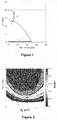
- Figure 1 depicts the refractive index profile of an optical fiber. It describes the relationship between the refractive index value n and the distance r from the center of the optical fiber.
- the optical fiber comprises an optical core for 0 ⁇ r ⁇ a and an optical cladding a ⁇ r surrounding the optical core.
- the fiber's optical cladding has a standard constant refractive index such as: n 0 ⁇ 1 ⁇ 2 ⁇ ⁇ .
- the fiber's optical core comprises a first core region having a radius a s and a refractive step-index with respect to a second core region, with a refractive index profile such as: n 0 ⁇ 1 ⁇ 2 ⁇ ⁇ ⁇ r a ⁇ + ⁇ s for r ⁇ a s
- the second core region which have a radius a , immediately surrounds the first core region and has a refractive graded-index profile (also known as "alpha index profile") with respect to the optical cladding such as: n 0 ⁇ 1 ⁇ 2 ⁇ ⁇ ⁇ r a ⁇ for a s ⁇ r ⁇ a
- the second core region presents the typical characteristics of a multimode fiber operating at a wavelength of 850 nm.
- the first core region is used to have a radial portion of the optical fiber that has a step-index profile whose the characteristics ( ⁇ s and a s ) with respect to the second region core enables to impose the single-mode transmission conditions operating at a wavelength of 1550 nm, while keeping the multimode characteristics of the optical fiber at 850 nm.
- the refractive index profile depicted in figure 1 exhibits a graded-index core with a step index positioned in the center of the optical core that is tuned to provide optical mode matching at 1550 nm between the fundamental mode of the hybrid optical fiber of the invention and the fundamental mode of a standard single-mode fiber.
- the first core region's radius a is about 25 ⁇ m (with a tolerance of ⁇ 2 ⁇ m) and the first core region's radius a s is about 6 ⁇ m.
- the parameter ⁇ of the optical core's index profile is about 2.
- the refractive index difference ⁇ s corresponding to the step-index may have a value of between about 3.10 -3 and 12.10 -3 .
- the refractive index difference ⁇ s and the radius a s of the first core region can be optimized in order to achieve the best trade-off in terms of optical properties, i.e. a high optical mode coupling ratio ⁇ 2 ⁇ i ⁇ i 2 for single-mode transmissions at 1550 nm and a low dispersion modal (or a high bandwidth) for multimode transmissions at 850 nm.
- the refractive index difference ⁇ s and the radius a s of the first core region can be such that they satisfy the following inequality: 0.0549 ⁇ a s 4 ⁇ 0.9053 ⁇ a s 3 + 5.483 ⁇ a s 2 ⁇ 14.39 ⁇ a s + 13.75 ⁇ 1000 ⁇ ⁇ s ⁇ 1.11 ⁇ a s 2 ⁇ 6.9145 ⁇ a s + 17.94
- the refractive index difference ⁇ s and the radius a s of the first core region are such that they satisfy the following inequality: 0.0373 ⁇ a s 4 ⁇ 0.6145 ⁇ a s 3 + 4.0286 ⁇ a s 2 ⁇ 12.217 ⁇ a s + 14.739 ⁇ 1000 ⁇ ⁇ s ⁇ 0.9821 ⁇ a s 2 ⁇ 6.5036 ⁇ a s + 16.7
- these two empiric inequalities each enables to improve the fundamental mode matching at 1550 nm.
- These empiric inequalities have been established by the inventors assuming that the fundamental mode matching can be assessed indirectly by the comparison to the mode field diameter of the fundamental mode of the hybrid optical fiber of the invention at 1550 nm and the fundamental mode of a standard single-mode fiber.
- these two inequalities correspond to a mode field diameter difference of about 0,8 ⁇ m and 0,5 ⁇ m respectively.
- the fundamental mode diameter is smaller, the optical power coupled into the fundamental mode (
- Table 1 shows fiber profile parameters of a standard multimode fiber that has a refractive graded-index profile optimized for providing error-free transmission at a wavelength of 850 nm. That prior art fiber is subjected to a optical signal of a wavelength ⁇ of 1550nm. Table 1 Examples ⁇ ⁇ a ⁇
- Table 2 below shows fiber profile parameters of a hybrid optical fiber according to the invention.
- the optical fiber exhibits a refractive index profile that respect the equation n(r) described above, with the refractive index difference ⁇ s and the radius a s of the first core region that comply with the first inequality: 0.0549 ⁇ a s 4 ⁇ 0.9053 ⁇ a s 3 + 5.483 ⁇ a s 2 ⁇ 14.39 ⁇ a s + 13.75 ⁇ 1000 ⁇ ⁇ s ⁇ 1.11 ⁇ a s 2 ⁇ 6.9145 ⁇ a s + 17.94 Table 2 Examples ⁇ a s ⁇ S a ⁇
- Figure 2 graphically depicts simulated optical mode coupling ratio (OMCR) measurements as a function of the refractive step-index difference ⁇ s and the radius a s of the first core region of an optical fiber for which the core radius is of 25 ⁇ m and the numerical aperture of 0,200.
- OMCR simulated optical mode coupling ratio
- the left-hand y-axis depicts the first core region's refractive step-index difference ⁇ s and the x-axis depicts the first core region's radius a s .
- the values of optical mode coupling ratio corresponding to a given pair of parameters ( ⁇ s , a s ) are illustrated in shades of gray in the right-hand y-axis.
- the curves 10 is defined by the following inequality, assuming that the optical power coupled into the fundamental mode is upper than 98% at the wavelength of 1550 nm (single-mode transmission): ⁇ s > 0.17173 a s 2 ⁇ 1.6926 a s + 5.1835
- the curves 11 is defined by the following inequality, assuming that the optical power coupled into the fundamental mode is upper than 98% at the wavelength of 1550 nm (single-mode transmission): ⁇ s > 0.31742 a s 2 ⁇ 2.9046 a s + 8.3221
- OMCR situated above curves 10 and 11 enable to establish the values of the parameters ⁇ s and a s of the optical fiber's first core region for which the fundamental mode-matching is provided at a ratio of at least 98%, respectively 99%, at the wavelength of 1550 nm.
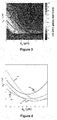
- Figure 3 graphically depicts simulated achievable 10GbE reach as a function of the refractive step-index difference ⁇ s and the radius a s of the first core region of an optical fiber for which the core radius is of 25 ⁇ m and the numerical aperture of 0,200.
- the left-hand y-axis depicts the first core region's refractive step-index difference ⁇ s and the x-axis depicts the first core region's radius a s .
- the values of achievable 10GbE reach, expressed as m (meter), at the wavelength of 850 nm, corresponding to a given ( ⁇ s , a s ) pair are illustrated in shades of gray in the right-hand y-axis.
- 10GbE reach refers to the maximum guaranteed transmission distance for which an optical fiber can operate at a nominal data rate of 10Gbps with a bit error rate (or BER) of less than 10 -12 when used with 10G-BASE-S sources (the 10G-BASE-S sources are standardized sources for 10GbE applications (see IEEE 802.3).
- the curves 12 is defined by the following inequality, assuming 10GbE reach of 30m: ⁇ s ⁇ 0.26184 a s 2 ⁇ 3.1935 a s + 10.5832
- the curves 13 is defined by the following inequality, assuming a 10GbE reach of 50m: ⁇ s ⁇ 0.21308 a s 2 ⁇ 2.3168 a s + 6.9690
- curves 12 and 13 enable to establish the values of the parameters ⁇ s and a s of the optical fiber's first core region for which the modal dispersion of the optical fiber at the wavelength of 850 nm is sufficiently low so that the optical fiber can be employed in high data rate applications (e.g. 10 GbE applications) over respectively 30 m and 50 m.
- Figure 4 depicts on a same graphic the curves 10, 11, 12, 13 obtained at figures 2 and 3 .
- This figure shows that the optical fiber has a pair of values ( ⁇ s , a s ) for which the corresponding point should be situated between the curves 10, 12 or between the curves 10, 13 or between the curves 11, 12 so that this optical fiber provides a satisfactory trade-off between the optical mode coupling ratio for single-mode transmissions at 1550 nm and the modal bandwidth for multimode transmissions at 850 nm.
- an optical fiber that possesses a first core region having a refractive step-index difference ⁇ s of 2,5.10 -3 and a radius of 3,5 ⁇ m will exhibit a value of OMCR of at least 99% at 1550 nm and an achievable 10GbE reach of at least 30 meters at 850 nm.
- the modal dispersion at 850nm is low enough to allow for an error free multimode transmission at 850nm using off-the-shelf 10Gbps transceivers (typically implementing a VCSEL technology) and an error free single-mode transmission at 1550nm.
- Figure 5 graphically depicts simulated optical mode coupling ratio (OMCR) measurements as a function of the refractive step-index difference ⁇ s and the radius a s of the first core region of an optical fiber for which the core radius is of 31,25 ⁇ m and the numerical aperture of 0,275.
- OMCR simulated optical mode coupling ratio
- the curves 14 is defined by the following inequality, assuming that the optical power coupled into the fundamental mode is upper than 98% at the wavelength of 1550 nm (single-mode transmission): ⁇ s > 0.13774 a s 2 ⁇ 1.3462 a s + 4.0572
- the curves 15 is defined by the following inequality, assuming that the optical power coupled into the fundamental mode is upper than 98% at the wavelength of 1550 nm (single-mode transmission): ⁇ s > 0.2839 a s 2 ⁇ 2.5787 a s + 7.2947
- OMCR situated above curves 14 and 15 enable to establish the values of the parameters ⁇ s and a s of the optical fiber's first core region for which the fundamental mode-matching is provided at a ratio of at least 98%, respectively 99%, at the wavelength of 1550 nm.
- Figure 6 graphically depicts simulated achievable 10GbE reach as a function of the refractive step-index difference ⁇ s and the radius a s of the first core region of an optical fiber for which the core radius is of 31,25 ⁇ m and the numerical aperture of 0,275.
- the curves 16 is defined by the following inequality, assuming a 10GbE reach of 30 m: ⁇ s ⁇ 0.22044 a s 2 ⁇ 2.7607 a s + 9.7057
- the curves 17 is defined by the following inequality, assuming a 10GbE reach of 50 m: ⁇ s ⁇ 0.15979 a s 2 ⁇ 1.8078 a s + 5.9286
- curves 16 and 17 enable to establish the values of the parameters ⁇ s and a s of the optical fiber's first core region for which the modal dispersion of the optical fiber at the wavelength of 850 nm is sufficiently low so that the optical fiber of can be employed in high data rate applications (typically 10 GbE applications) over respectively 30 m and 50 m.
- Figure 7 depicts on a same graphic the curves 14, 15, 16, 17 obtained at figures 5 and 6 .
- This figure shows that the optical fiber has a pair of values ( ⁇ s , a s ) for which the corresponding point should be situated between the curves 14 and 16 or between the curves 14 and 17 or between the curves 15 and 16 or 15 and 17, so that this optical fiber provides a satisfactory trade-off between the optical mode coupling ratio at 1550 nm and the modal bandwidth at 850 nm.
- an optical fiber that possesses a first core region having a refractive step-index difference ⁇ s of 2,0.10 -3 and a radius of 4 ⁇ m will exhibit a value of OMCR of at least 99% at 1550 nm and an achievable 10GbE reach of at least 30 meters at 850 nm.
- the modal dispersion at 850nm is low enough to allow for an error free multimode transmission at 850nm using off-the-shelf 10Gbps transceivers (typically implementing a VCSEL technology) and an error free single-mode transmission at 1550nm.
- Figure 8 graphically depicts simulated optical mode coupling ratio (OMCR) measurements as a function of the refractive step-index difference ⁇ s and the radius a s of the first core region of an optical fiber for which the core radius is of 40 ⁇ m and the numerical aperture of 0,290.
- OMCR simulated optical mode coupling ratio
- the curves 18 is defined by the following inequality, assuming that the optical power coupled into the fundamental mode is upper than 98% at the wavelength of 1550 nm (single-mode transmission): ⁇ s > 0.20185 a s 2 ⁇ 2.0205 a s + 6.2914
- the curves 19 is defined by the following inequality, assuming that the optical power coupled into the fundamental mode is upper than 98% at the wavelength of 1550 nm (single-mode transmission): ⁇ s > 0.34616 a s 2 ⁇ 3.211 a s + 9.3320
- OMCR situated above curves 18 and 19 enable to establish the values of the parameters ⁇ s and a s of the optical fiber's first core region for which the fundamental mode-matching is provided at a ratio of at least 98%, respectively 99%, at the wavelength of 1550 nm.
- Figure 9 graphically depicts simulated achievable 10GbE reach as a function of the refractive step-index difference ⁇ s and the radius a s of the first core region of an optical fiber for which the core radius is of 40 ⁇ m and the numerical aperture of 0,290.
- the curves 20 is defined by the following inequality, assuming a 10GbE reach of 30 m: ⁇ s ⁇ 0.26946 a s 2 ⁇ 3.5101 a s + 12.8205
- the curves 21 is defined by the following inequality, assuming a 10GbE reach of 50 m: ⁇ s ⁇ 0.20605 a s 2 ⁇ 2.4798 a s + 8.3655
- curves 21 and 22 enable to establish the values of the parameters ⁇ s and a s of the optical fiber's first core region for which the modal dispersion of the optical fiber at the wavelength of 850 nm is sufficiently low so that the optical fiber can be employed in high data rate applications (e.g. 10 GbE applications) over respectively 30 m and 50 m.
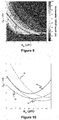
- Figure 10 depicts on a same graphic the curves 18, 19, 20, 21 obtained at figures 8 and 9 .
- This figure shows that the optical fiber has a pair of values ( ⁇ s , a s ) for which the corresponding point should be situated between the curves 18 and 20 or between the curves 18 and 12 or between the curves 19 and 20 or 19 and 21, so that this optical fiber provides a satisfactory trade-off between the optical mode coupling ratio at 1550 nm and the modal bandwidth at 850 nm.
- an optical fiber that possesses a first core region having a refractive step-index difference ⁇ s of 2,0.10 -3 and a radius of 4 ⁇ m will exhibit a value of OMCR of at least 99% at 1550 nm and an achievable 10GbE reach of at least 30 meters at 850 nm.
- the modal dispersion at 850nm is low enough to allow for an error free multimode transmission at 850nm using off-the-shelf 10Gbps transceivers (typically implementing a VCSEL technology) and an error free single-mode transmission at 1550nm.
- Figure 11 graphically provides the refractive index profile of an optical fiber according to a second embodiment of the invention.
- This second embodiment differs from the second embodiment of the invention in that the optical fiber comprises a depressed area positioned between the first core region and the second core region, surrounding immediately the first core region.
- the depressed area aims at reducing even more the dispersion modal for multimode transmissions at 850 nm.
- This depressed area has a width w d of about 4 ⁇ m and a refractive index difference ⁇ d with respect to the second core region of about -1,3. 10 -3 .
- the refractive index difference ⁇ s ' of the step-index first core region is about 2,5.10 -3 .
- the width w d of the depressed area may have a value of between about 1 ⁇ m and 8 ⁇ m.
- the refractive index difference ⁇ d of the depressed area and the refractive index difference ⁇ s ' of the first core region may be determined using the following equation:
- + ⁇ s ' ⁇ s , wherein ⁇ s satisfies at least one of the inequalities described here above in relation the first embodiment of the invention.
- of the depressed area and the refractive index difference ⁇ s ' of the first core region may have a value of between about 3.10 -3 and 12.10 -3 , with ⁇ d comprised between -4,5.10 -3 and -0,5.10 -3 .
Landscapes
- Physics & Mathematics (AREA)
- General Physics & Mathematics (AREA)
- Optics & Photonics (AREA)
- Chemical & Material Sciences (AREA)
- Dispersion Chemistry (AREA)
- Optical Communication System (AREA)
- Lasers (AREA)
- Optical Couplings Of Light Guides (AREA)
Applications Claiming Priority (1)
| Application Number | Priority Date | Filing Date | Title |
|---|---|---|---|
| PCT/IB2012/001174 WO2013160714A1 (en) | 2012-04-27 | 2012-04-27 | Hybrid single and multimode optical fiber for a home network |
Publications (2)
| Publication Number | Publication Date |
|---|---|
| EP2657734A1 EP2657734A1 (en) | 2013-10-30 |
| EP2657734B1 true EP2657734B1 (en) | 2019-10-30 |
Family
ID=48182838
Family Applications (1)
| Application Number | Title | Priority Date | Filing Date |
|---|---|---|---|
| EP13165638.1A Active EP2657734B1 (en) | 2012-04-27 | 2013-04-26 | Hybrid single and multimode optical fiber for a home network |
Country Status (6)
| Country | Link |
|---|---|
| US (2) | US9563012B2 (da) |
| EP (1) | EP2657734B1 (da) |
| CN (1) | CN103492918B (da) |
| BR (1) | BR102013010486B1 (da) |
| DK (1) | DK2657734T3 (da) |
| WO (2) | WO2013160714A1 (da) |
Families Citing this family (16)
| Publication number | Priority date | Publication date | Assignee | Title |
|---|---|---|---|---|
| WO2013160714A1 (en) | 2012-04-27 | 2013-10-31 | Draka Comteq Bv | Hybrid single and multimode optical fiber for a home network |
| BR112015002445B1 (pt) | 2012-10-11 | 2021-01-05 | Draka Comteq Bv | fibra óptica multimodo de largura de banda alta otimizada para transmissões multimodo e modo único |
| NL2011075C2 (en) | 2013-07-01 | 2015-01-05 | Draka Comteq Bv | Pcvd process with removal of substrate tube. |
| US9678269B2 (en) | 2014-05-16 | 2017-06-13 | Corning Incorporated | Multimode optical fiber transmission system including single mode fiber |
| US20150331181A1 (en) * | 2014-05-16 | 2015-11-19 | Corning Incorporated | Multimode optical fiber and system including such |
| KR102466728B1 (ko) | 2016-03-07 | 2022-11-15 | 다우 글로벌 테크놀로지스 엘엘씨 | 광섬유 케이블 부품을 위한 중합체 조성물 |
| JP7266525B2 (ja) * | 2017-01-19 | 2023-04-28 | コーニング インコーポレイテッド | ハイブリッドコア光ファイバを採用した分布型ファイバセンサ及びシステム |
| KR102545899B1 (ko) | 2017-09-06 | 2023-06-22 | 롬 앤드 하스 캄파니 | 광섬유 케이블 구성요소를 위한 중합체성 조성물 |
| EP3562066A1 (en) * | 2018-04-27 | 2019-10-30 | Institut Mines-Telecom | Optical transmission system and method for core selection in multi-core fibers |
| GB2574883B (en) * | 2018-06-22 | 2022-10-19 | Fibercore Ltd | Optical fiber |
| EP3847489A1 (en) | 2018-09-04 | 2021-07-14 | Panduit Corp. | Smf to mmf coupler |
| WO2020069053A1 (en) * | 2018-09-28 | 2020-04-02 | Corning Research & Development Corporation | Small diameter fiber optic cables having low-friction cable jackets and optical fibers with reduced cladding and coating diameters |
| CN111381312B (zh) * | 2018-12-29 | 2025-03-18 | 中天科技光纤有限公司 | 新型光纤 |
| CA3149247A1 (en) | 2019-09-13 | 2021-03-18 | Karl M. SEVEN | Compatibilized polymeric compositions for optical fiber cable components |
| WO2021096723A1 (en) | 2019-11-11 | 2021-05-20 | Dow Global Technologies Llc | Polymeric compositions for optical fiber cable components |
| CN116710822A (zh) * | 2021-01-05 | 2023-09-05 | 日本电信电话株式会社 | 光纤 |
Family Cites Families (147)
| Publication number | Priority date | Publication date | Assignee | Title |
|---|---|---|---|---|
| HU179404B (en) | 1978-11-10 | 1982-10-28 | Magyar Aluminium | Process for decomposition of organic materials in aluminate liquor of alum earth-production according to the bayer method,and for separating solide decomposition products |
| JPH01113708A (ja) * | 1987-10-27 | 1989-05-02 | Mitsubishi Electric Corp | 光合分波モジュール |
| US4838643A (en) | 1988-03-23 | 1989-06-13 | Alcatel Na, Inc. | Single mode bend insensitive fiber for use in fiber optic guidance applications |
| JPH0273203A (ja) * | 1988-09-08 | 1990-03-13 | Nippon Telegr & Teleph Corp <Ntt> | 光ファイバ |
| FR2647778B1 (fr) | 1989-06-05 | 1992-11-20 | Comp Generale Electricite | Procede et dispositif de depot externe par plasma de silice exempte d'ions hydroxyles |
| US5416862A (en) * | 1993-04-07 | 1995-05-16 | At&T Corp. | Lightwave transmission system using selected optical modes |
| FR2713621B1 (fr) | 1993-12-14 | 1996-01-05 | Alcatel Fibres Optiques | Procédé de recharge par plasma d'une préforme pour fibre optique et fibre optique issue de la préforme rechargée selon ce procédé. |
| US5574816A (en) | 1995-01-24 | 1996-11-12 | Alcatel Na Cable Sytems, Inc. | Polypropylene-polyethylene copolymer buffer tubes for optical fiber cables and method for making the same |
| US5717805A (en) | 1996-06-12 | 1998-02-10 | Alcatel Na Cable Systems, Inc. | Stress concentrations in an optical fiber ribbon to facilitate separation of ribbon matrix material |
| US7322122B2 (en) | 1997-01-15 | 2008-01-29 | Draka Comteq B.V. | Method and apparatus for curing a fiber having at least two fiber coating curing stages |
| FR2762836B1 (fr) | 1997-05-02 | 1999-07-23 | Alsthom Cge Alcatel | Procede et appareil de fabrication de preformes de fibre de verre |
| FR2760540B1 (fr) | 1997-03-10 | 1999-04-16 | Alsthom Cge Alcatel | Cable a fibres optiques serrees dans une gaine |
| US5911023A (en) | 1997-07-10 | 1999-06-08 | Alcatel Alsthom Compagnie Generale D'electricite | Polyolefin materials suitable for optical fiber cable components |
| US6269663B1 (en) | 1998-03-05 | 2001-08-07 | Alcatel | Method of purifying silica and depositing on an optical fiber preform |
| US6066397A (en) | 1998-03-31 | 2000-05-23 | Alcatel | Polypropylene filler rods for optical fiber communications cables |
| US6175677B1 (en) | 1998-04-17 | 2001-01-16 | Alcatel | Optical fiber multi-ribbon and method for making the same |
| US6085009A (en) | 1998-05-12 | 2000-07-04 | Alcatel | Water blocking gels compatible with polyolefin optical fiber cable buffer tubes and cables made therewith |
| US6215931B1 (en) | 1999-01-26 | 2001-04-10 | Alcatel | Flexible thermoplastic polyolefin elastomers for buffering transmission elements in a telecommunications cable |
| JP2000241649A (ja) * | 1999-02-18 | 2000-09-08 | Kdd Corp | 光ビーム径低減装置 |
| US6134363A (en) | 1999-02-18 | 2000-10-17 | Alcatel | Method for accessing optical fibers in the midspan region of an optical fiber cable |
| US6381390B1 (en) | 1999-04-06 | 2002-04-30 | Alcatel | Color-coded optical fiber ribbon and die for making the same |
| US6181857B1 (en) | 1999-05-12 | 2001-01-30 | Alcatel | Method for accessing optical fibers contained in a sheath |
| US6314224B1 (en) | 1999-06-18 | 2001-11-06 | Alcatel | Thick-walled cable jacket with non-circular cavity cross section |
| US6334016B1 (en) | 1999-06-30 | 2001-12-25 | Alcatel | Optical fiber ribbon matrix material having optimal handling characteristics |
| US6321012B1 (en) | 1999-08-30 | 2001-11-20 | Alcatel | Optical fiber having water swellable material for identifying grouping of fiber groups |
| US6493491B1 (en) | 1999-09-28 | 2002-12-10 | Alcatel | Optical drop cable for aerial installation |
| US6321014B1 (en) | 1999-11-01 | 2001-11-20 | Alcatel | Method for manufacturing optical fiber ribbon |
| FR2809499B1 (fr) | 2000-05-29 | 2003-10-03 | Cit Alcatel | Peau de protection pour fibres optiques |
| US6603908B2 (en) | 2000-08-04 | 2003-08-05 | Alcatel | Buffer tube that results in easy access to and low attenuation of fibers disposed within buffer tube |
| JP3829665B2 (ja) * | 2000-09-29 | 2006-10-04 | 住友電気工業株式会社 | 光ファイバカプラ及び光ファイバカプラ用の光ファイバ |
| AUPR138500A0 (en) * | 2000-11-10 | 2000-12-07 | Redfern Broadband Networks Incorporated | Optical fibre |
| US6922515B2 (en) | 2000-12-20 | 2005-07-26 | Alcatel | Method and apparatus to reduce variation of excess fiber length in buffer tubes of fiber optic cables |
| US6618538B2 (en) | 2000-12-20 | 2003-09-09 | Alcatel | Method and apparatus to reduce variation of excess fiber length in buffer tubes of fiber optic cables |
| US7346244B2 (en) | 2001-03-23 | 2008-03-18 | Draka Comteq B.V. | Coated central strength member for fiber optic cables with reduced shrinkage |
| US7045010B2 (en) | 2001-09-06 | 2006-05-16 | Alcatel | Applicator for high-speed gel buffering of flextube optical fiber bundles |
| US6749446B2 (en) | 2001-10-10 | 2004-06-15 | Alcatel | Optical fiber cable with cushion members protecting optical fiber ribbon stack |
| US6798962B2 (en) | 2002-02-26 | 2004-09-28 | Corning Incorporated | Broadband access optimized fiber and method of making |
| AU2002100296A4 (en) | 2002-04-16 | 2002-05-30 | Redfern Broadband Networks Inc. | Optical fibre |
| US6912347B2 (en) | 2002-11-15 | 2005-06-28 | Alcatel | Optimized fiber optic cable suitable for microduct blown installation |
| US6990277B2 (en) * | 2003-04-04 | 2006-01-24 | Fitel Usa Corp. | Enhanced multimode fiber |
| US6839484B2 (en) * | 2003-04-04 | 2005-01-04 | Fitel Usa Corp. | Optical fiber for single-mode operation |
| FR2855619B1 (fr) * | 2003-05-27 | 2005-07-22 | Cit Alcatel | Fibre optique pour amplification ou pour emission laser |
| US6941049B2 (en) | 2003-06-18 | 2005-09-06 | Alcatel | Fiber optic cable having no rigid strength members and a reduced coefficient of thermal expansion |
| ES2297604T3 (es) | 2004-01-26 | 2008-05-01 | Draka Comteq B.V. | Arrollamiento de acoplamiento para un tubo de proteccion y metodo para instalacion de un cable de fibras. |
| US7336877B2 (en) | 2004-08-31 | 2008-02-26 | Corning Incorporated | Broadband optical fiber |
| WO2007013923A2 (en) | 2005-07-20 | 2007-02-01 | Draka Comteq | Grease-free buffer optical fiber buffer tube construction utilizing a water-swellable, texturized yarn |
| US7599589B2 (en) | 2005-07-20 | 2009-10-06 | Draka Comteq B.V. | Gel-free buffer tube with adhesively coupled optical element |
| US7515795B2 (en) | 2005-07-20 | 2009-04-07 | Draka Comteq B.V. | Water-swellable tape, adhesive-backed for coupling when used inside a buffer tube |
| US7567739B2 (en) | 2007-01-31 | 2009-07-28 | Draka Comteq B.V. | Fiber optic cable having a water-swellable element |
| FR2893149B1 (fr) | 2005-11-10 | 2008-01-11 | Draka Comteq France | Fibre optique monomode. |
| FR2896795B1 (fr) | 2006-01-27 | 2008-04-18 | Draka Compteq France | Procede de fabrication d'une preforme de fibre optique |
| WO2007091879A1 (en) | 2006-02-08 | 2007-08-16 | Draka Comteq B.V. | Optical fiber cable suited for blown installation or pushing installation in microducts of small diameter |
| US7406237B2 (en) * | 2006-02-21 | 2008-07-29 | Corning Incorporated | Multiband optical fiber |
| FR2899693B1 (fr) | 2006-04-10 | 2008-08-22 | Draka Comteq France | Fibre optique monomode. |
| FR2900739B1 (fr) | 2006-05-03 | 2008-07-04 | Draka Comteq France | Fibre de compensation de la dispersion chromatique |
| NL1031792C2 (nl) | 2006-05-11 | 2007-11-13 | Draka Comteq Bv | Kabelsamenstel alsmede werkwijze voor het installeren van een dergelijk kabelsamenstel. |
| US7665902B2 (en) | 2006-05-11 | 2010-02-23 | Draka Comteq, B.V. | Modified pre-ferrulized communication cable assembly and installation method |
| FR2903501B1 (fr) | 2006-07-04 | 2008-08-22 | Draka Comteq France Sa | Fibre optique dopee au fluor |
| FR2904876B1 (fr) | 2006-08-08 | 2008-11-21 | Draka Comteq France | Cable de telecommunication a fibres optiques |
| FR2908250B1 (fr) | 2006-11-03 | 2009-01-09 | Draka Comteq France Sa Sa | Fibre de compensation de la dispersion chromatique |
| FR2908525B1 (fr) | 2006-11-10 | 2009-06-26 | Draka Comteq France Sa Sa | Cable de telecommunication a fibres optiques |
| EP1930753B1 (en) | 2006-12-04 | 2015-02-18 | Draka Comteq B.V. | Optical fiber with high Brillouin threshold power and low bending losses |
| FR2914751B1 (fr) | 2007-04-06 | 2009-07-03 | Draka Comteq France | Fibre optique monomode |
| FR2915002B1 (fr) | 2007-04-11 | 2009-11-06 | Draka Comteq France | Procede d'acces a une ou plusieurs fibres optiques d'un cable de telecommunication |
| US7724998B2 (en) | 2007-06-28 | 2010-05-25 | Draka Comteq B.V. | Coupling composition for optical fiber cables |
| US7646952B2 (en) | 2007-06-28 | 2010-01-12 | Draka Comteq B.V. | Optical fiber cable having raised coupling supports |
| US7639915B2 (en) | 2007-06-28 | 2009-12-29 | Draka Comteq B.V. | Optical fiber cable having a deformable coupling element |
| CN101373237B (zh) * | 2007-08-22 | 2010-05-26 | 富通集团有限公司 | 一种优化色散特性的单模光纤 |
| FR2922657B1 (fr) | 2007-10-23 | 2010-02-12 | Draka Comteq France | Fibre multimode. |
| US8031997B2 (en) | 2007-11-09 | 2011-10-04 | Draka Comteq, B.V. | Reduced-diameter, easy-access loose tube cable |
| US8041168B2 (en) | 2007-11-09 | 2011-10-18 | Draka Comteq, B.V. | Reduced-diameter ribbon cables with high-performance optical fiber |
| US8145026B2 (en) | 2007-11-09 | 2012-03-27 | Draka Comteq, B.V. | Reduced-size flat drop cable |
| US8081853B2 (en) | 2007-11-09 | 2011-12-20 | Draka Comteq, B.V. | Single-fiber drop cables for MDU deployments |
| US8165439B2 (en) | 2007-11-09 | 2012-04-24 | Draka Comteq, B.V. | ADSS cables with high-performance optical fiber |
| US8041167B2 (en) | 2007-11-09 | 2011-10-18 | Draka Comteq, B.V. | Optical-fiber loose tube cables |
| US8467650B2 (en) | 2007-11-09 | 2013-06-18 | Draka Comteq, B.V. | High-fiber-density optical-fiber cable |
| DK2206001T3 (da) | 2007-11-09 | 2014-07-07 | Draka Comteq Bv | Optisk fiber, der er modstandsdygtig over for mikrobøjning |
| US20090214167A1 (en) | 2008-02-25 | 2009-08-27 | Draka Comteq B.V. | Optical Cable Buffer Tube with Integrated Hollow Channels |
| FR2929716B1 (fr) | 2008-04-04 | 2011-09-16 | Draka Comteq France Sa | Fibre optique a dispersion decalee. |
| FR2930997B1 (fr) | 2008-05-06 | 2010-08-13 | Draka Comteq France Sa | Fibre optique monomode |
| FR2931253B1 (fr) | 2008-05-16 | 2010-08-20 | Draka Comteq France Sa | Cable de telecommunication a fibres optiques |
| FR2932932B1 (fr) | 2008-06-23 | 2010-08-13 | Draka Comteq France Sa | Systeme optique multiplexe en longueur d'ondes avec fibres optiques multimodes |
| FR2933779B1 (fr) | 2008-07-08 | 2010-08-27 | Draka Comteq France | Fibres optiques multimodes |
| US8401353B2 (en) | 2008-09-12 | 2013-03-19 | Draka Comteq B.V. | Optical fiber cable assembly |
| US7974507B2 (en) | 2008-09-12 | 2011-07-05 | Draka Comteq, B.V. | High-fiber-density optical fiber cable |
| US7970247B2 (en) | 2008-09-12 | 2011-06-28 | Draka Comteq B.V. | Buffer tubes for mid-span storage |
| JP5588451B2 (ja) | 2008-11-07 | 2014-09-10 | ドラカ・コムテツク・ベー・ベー | 小径光ファイバ |
| FR2938389B1 (fr) | 2008-11-07 | 2011-04-15 | Draka Comteq France | Systeme optique multimode |
| EP2187486B1 (en) | 2008-11-12 | 2014-04-23 | Draka Comteq B.V. | Amplifying optical fiber and method of manufacturing |
| FR2939246B1 (fr) | 2008-12-02 | 2010-12-24 | Draka Comteq France | Fibre optique amplificatrice et procede de fabrication |
| FR2939522B1 (fr) | 2008-12-08 | 2011-02-11 | Draka Comteq France | Fibre optique amplificatrice resistante aux radiations ionisantes |
| FR2939911B1 (fr) | 2008-12-12 | 2011-04-08 | Draka Comteq France | Fibre optique gainee, cable de telecommunication comportant plusieurs fibres optiques et procede de fabrication d'une telle fibre |
| NL1036343C2 (nl) | 2008-12-19 | 2010-06-22 | Draka Comteq Bv | Werkwijze en inrichting voor het vervaardigen van een optische voorvorm. |
| US8081854B2 (en) * | 2008-12-19 | 2011-12-20 | Sehf-Korea Co., Ltd. | Low bend loss optical fiber |
| US8891923B2 (en) | 2008-12-30 | 2014-11-18 | Draka Comteq, B.V. | Perforated water-blocking element |
| US8314408B2 (en) | 2008-12-31 | 2012-11-20 | Draka Comteq, B.V. | UVLED apparatus for curing glass-fiber coatings |
| FR2940839B1 (fr) | 2009-01-08 | 2012-09-14 | Draka Comteq France | Fibre optique multimodale a gradient d'indice, procedes de caracterisation et de fabrication d'une telle fibre |
| FR2941539B1 (fr) | 2009-01-23 | 2011-02-25 | Draka Comteq France | Fibre optique monomode |
| FR2941540B1 (fr) | 2009-01-27 | 2011-05-06 | Draka Comteq France | Fibre optique monomode presentant une surface effective elargie |
| FR2941541B1 (fr) | 2009-01-27 | 2011-02-25 | Draka Comteq France | Fibre optique monomode |
| US9360647B2 (en) | 2009-02-06 | 2016-06-07 | Draka Comteq, B.V. | Central-tube cable with high-conductivity conductors encapsulated with high-dielectric-strength insulation |
| FR2942571B1 (fr) | 2009-02-20 | 2011-02-25 | Draka Comteq France | Fibre optique amplificatrice comprenant des nanostructures |
| FR2942551B1 (fr) | 2009-02-23 | 2011-07-15 | Draka Comteq France | Cable comportant des elements a extraire, procede d'extraction desdits elements et procede de fabrication associe |
| FR2946436B1 (fr) | 2009-06-05 | 2011-12-09 | Draka Comteq France | Fibre optique multimode a tres large bande passante avec une interface coeur-gaine optimisee |
| US20110026889A1 (en) | 2009-07-31 | 2011-02-03 | Draka Comteq B.V. | Tight-Buffered Optical Fiber Unit Having Improved Accessibility |
| FR2957153B1 (fr) | 2010-03-02 | 2012-08-10 | Draka Comteq France | Fibre optique multimode a large bande passante et a faibles pertes par courbure |
| FR2953030B1 (fr) | 2009-11-25 | 2011-11-18 | Draka Comteq France | Fibre optique multimode a tres large bande passante avec une interface coeur-gaine optimisee |
| FR2953029B1 (fr) | 2009-11-25 | 2011-11-18 | Draka Comteq France | Fibre optique multimode a tres large bande passante avec une interface coeur-gaine optimisee |
| FR2953606B1 (fr) | 2009-12-03 | 2012-04-27 | Draka Comteq France | Fibre optique multimode a large bande passante et a faibles pertes par courbure |
| FR2949870B1 (fr) | 2009-09-09 | 2011-12-16 | Draka Compteq France | Fibre optique multimode presentant des pertes en courbure ameliorees |
| US9014525B2 (en) | 2009-09-09 | 2015-04-21 | Draka Comteq, B.V. | Trench-assisted multimode optical fiber |
| FR2953605B1 (fr) | 2009-12-03 | 2011-12-16 | Draka Comteq France | Fibre optique multimode a large bande passante et a faibles pertes par courbure |
| US8306380B2 (en) | 2009-09-14 | 2012-11-06 | Draka Comteq, B.V. | Methods and devices for cable insertion into latched-duct conduit |
| FR2950156B1 (fr) * | 2009-09-17 | 2011-11-18 | Draka Comteq France | Fibre optique multimode |
| FR2950443B1 (fr) | 2009-09-22 | 2011-11-18 | Draka Comteq France | Fibre optique pour la generation de frequence somme et son procede de fabrication |
| US8805143B2 (en) | 2009-10-19 | 2014-08-12 | Draka Comteq, B.V. | Optical-fiber cable having high fiber count and high fiber density |
| FR2952634B1 (fr) | 2009-11-13 | 2011-12-16 | Draka Comteq France | Fibre en silice dopee en terre rare a faible ouverture numerique |
| US9042693B2 (en) | 2010-01-20 | 2015-05-26 | Draka Comteq, B.V. | Water-soluble water-blocking element |
| EP2352046B1 (en) | 2010-02-01 | 2018-08-08 | Draka Comteq B.V. | Non-zero dispersion shifted optical fiber having a short cutoff wavelength |
| EP2352047B1 (en) | 2010-02-01 | 2019-09-25 | Draka Comteq B.V. | Non-zero dispersion shifted optical fiber having a large effective area |
| ES2539824T3 (es) | 2010-03-17 | 2015-07-06 | Draka Comteq B.V. | Fibra óptica de modo único con reducidas pérdidas por curvatura |
| US8693830B2 (en) | 2010-04-28 | 2014-04-08 | Draka Comteq, B.V. | Data-center cable |
| PT2390700T (pt) | 2010-05-03 | 2016-10-19 | Draka Comteq Bv | Cabos de fibra ótica empacotados |
| DK2388239T3 (da) | 2010-05-20 | 2017-04-24 | Draka Comteq Bv | Hærdningsapparat, der anvender vinklede UV-LED'er |
| US8871311B2 (en) | 2010-06-03 | 2014-10-28 | Draka Comteq, B.V. | Curing method employing UV sources that emit differing ranges of UV radiation |
| FR2962230B1 (fr) | 2010-07-02 | 2012-07-27 | Draka Comteq France | Fibre optique monomode |
| US8682123B2 (en) | 2010-07-15 | 2014-03-25 | Draka Comteq, B.V. | Adhesively coupled optical fibers and enclosing tape |
| DK2418183T3 (da) | 2010-08-10 | 2018-11-12 | Draka Comteq Bv | Fremgangsmåde til hærdning af coatede glasfibre, som tilvejebringer øget UVLED-intensitet |
| FR2963787B1 (fr) | 2010-08-10 | 2012-09-21 | Draka Comteq France | Procede de fabrication d'une preforme de fibre optique |
| US8571369B2 (en) | 2010-09-03 | 2013-10-29 | Draka Comteq B.V. | Optical-fiber module having improved accessibility |
| FR2966256B1 (fr) | 2010-10-18 | 2012-11-16 | Draka Comteq France | Fibre optique multimode insensible aux pertes par |
| FR2968092B1 (fr) | 2010-11-25 | 2012-12-14 | Draka Comteq France | Fibre optique dopee en terres rares insensible aux irradiations |
| FR2968775B1 (fr) | 2010-12-10 | 2012-12-21 | Draka Comteq France | Fibre optique dopee en terres rares presentant de faibles interactions entre les elements dopants |
| FR2971061B1 (fr) | 2011-01-31 | 2013-02-08 | Draka Comteq France | Fibre optique a large bande passante et a faibles pertes par courbure |
| DK2482106T5 (da) | 2011-01-31 | 2014-09-22 | Draka Comteq Bv | Multimode-fiber |
| WO2012161775A1 (en) | 2011-02-21 | 2012-11-29 | Draka Comteq B.V. | Optical-fiber interconnect cable |
| EP2495589A1 (en) | 2011-03-04 | 2012-09-05 | Draka Comteq B.V. | Rare earth doped amplifying optical fiber for compact devices and method of manufacturing thereof |
| EP2503368A1 (en) | 2011-03-24 | 2012-09-26 | Draka Comteq B.V. | Multimode optical fiber with improved bend resistance |
| EP2506044A1 (en) | 2011-03-29 | 2012-10-03 | Draka Comteq B.V. | Multimode optical fiber |
| EP2518546B1 (en) | 2011-04-27 | 2018-06-20 | Draka Comteq B.V. | High-bandwidth, radiation-resistant multimode optical fiber |
| DK2527893T3 (da) | 2011-05-27 | 2013-12-16 | Draka Comteq Bv | Optisk singlemode fiber |
| ES2451369T3 (es) | 2011-06-09 | 2014-03-26 | Draka Comteq Bv | Fibra óptica de modo único |
| DK2541292T3 (da) | 2011-07-01 | 2014-12-01 | Draka Comteq Bv | Optisk multimode fiber |
| EP2584340A1 (en) | 2011-10-20 | 2013-04-24 | Draka Comteq BV | Hydrogen sensing fiber and hydrogen sensor |
| NL2007831C2 (en) | 2011-11-21 | 2013-05-23 | Draka Comteq Bv | Apparatus and method for carrying out a pcvd deposition process. |
| US8929701B2 (en) | 2012-02-15 | 2015-01-06 | Draka Comteq, B.V. | Loose-tube optical-fiber cable |
| WO2013160714A1 (en) | 2012-04-27 | 2013-10-31 | Draka Comteq Bv | Hybrid single and multimode optical fiber for a home network |
-
2012
- 2012-04-27 WO PCT/IB2012/001174 patent/WO2013160714A1/en not_active Ceased
-
2013
- 2013-04-26 DK DK13165638.1T patent/DK2657734T3/da active
- 2013-04-26 CN CN201380000341.2A patent/CN103492918B/zh active Active
- 2013-04-26 WO PCT/EP2013/058796 patent/WO2013160466A1/en not_active Ceased
- 2013-04-26 EP EP13165638.1A patent/EP2657734B1/en active Active
- 2013-04-29 BR BR102013010486-8A patent/BR102013010486B1/pt active IP Right Grant
- 2013-04-29 US US13/872,397 patent/US9563012B2/en active Active
-
2017
- 2017-01-24 US US15/413,517 patent/US9869814B2/en active Active
Non-Patent Citations (1)
| Title |
|---|
| None * |
Also Published As
| Publication number | Publication date |
|---|---|
| US9869814B2 (en) | 2018-01-16 |
| WO2013160714A1 (en) | 2013-10-31 |
| US20130287353A1 (en) | 2013-10-31 |
| WO2013160466A1 (en) | 2013-10-31 |
| EP2657734A1 (en) | 2013-10-30 |
| US20170131465A1 (en) | 2017-05-11 |
| US9563012B2 (en) | 2017-02-07 |
| BR102013010486B1 (pt) | 2021-04-27 |
| DK2657734T3 (da) | 2019-12-16 |
| CN103492918A (zh) | 2014-01-01 |
| CN103492918B (zh) | 2017-05-17 |
| BR102013010486A2 (pt) | 2015-06-23 |
Similar Documents
| Publication | Publication Date | Title |
|---|---|---|
| EP2657734B1 (en) | Hybrid single and multimode optical fiber for a home network | |
| EP2906976B1 (en) | High bandwidth multimode optical fiber optimized for multimode and single-mode transmissions | |
| EP3399357B1 (en) | Non-zero dispersion shifted optical fiber having a short cutoff wavelength | |
| CN108700703B (zh) | 模分复用所用的少模光纤 | |
| EP2894498B1 (en) | Optical fiber | |
| EP2562571B1 (en) | Optical fiber | |
| EP2352047A1 (en) | Non-zero dispersion shifted optical fiber having a large effective area | |
| EP2362252A1 (en) | Optical fiber and optical communication system including same | |
| US8971683B2 (en) | Multimode optical fiber and systems comprising such fiber | |
| US10989864B2 (en) | Optical fiber, coated optical fiber, and optical transmission system | |
| US11280958B2 (en) | Optical fiber, colored optical fiber, and optical transmission system | |
| EP1806599A1 (en) | Optical fiber, transmission system and multiple wavelength transmission system | |
| CN102193140B (zh) | 光纤及包含光纤的光通信系统 | |
| CN110418990A (zh) | 空分复用所用的弱耦合少模光纤 | |
| US7164829B2 (en) | Optical fiber, optical transmission line and optical communications system | |
| JP2005004216A (ja) | 大きな有効断面積を有する逆分散補償ファイバ、およびそれを組み込んだ光ファイバ通信システム | |
| US20130259426A1 (en) | Single-mode optical fibers for optical fiber connectors | |
| US6850678B2 (en) | Reduced four-wave mixing optical fiber for wavelength-division multiplexing | |
| EP2362251B1 (en) | Optical fibers with truncated cores | |
| US11137540B2 (en) | Non-zero dispersion shifted fiber with low cut off wavelength and large effective area |
Legal Events
| Date | Code | Title | Description |
|---|---|---|---|
| PUAI | Public reference made under article 153(3) epc to a published international application that has entered the european phase |
Free format text: ORIGINAL CODE: 0009012 |
|
| AK | Designated contracting states |
Kind code of ref document: A1 Designated state(s): AL AT BE BG CH CY CZ DE DK EE ES FI FR GB GR HR HU IE IS IT LI LT LU LV MC MK MT NL NO PL PT RO RS SE SI SK SM TR |
|
| AX | Request for extension of the european patent |
Extension state: BA ME |
|
| 17P | Request for examination filed |
Effective date: 20140428 |
|
| RBV | Designated contracting states (corrected) |
Designated state(s): AL AT BE BG CH CY CZ DE DK EE ES FI FR GB GR HR HU IE IS IT LI LT LU LV MC MK MT NL NO PL PT RO RS SE SI SK SM TR |
|
| STAA | Information on the status of an ep patent application or granted ep patent |
Free format text: STATUS: EXAMINATION IS IN PROGRESS |
|
| 17Q | First examination report despatched |
Effective date: 20170313 |
|
| GRAP | Despatch of communication of intention to grant a patent |
Free format text: ORIGINAL CODE: EPIDOSNIGR1 |
|
| STAA | Information on the status of an ep patent application or granted ep patent |
Free format text: STATUS: GRANT OF PATENT IS INTENDED |
|
| INTG | Intention to grant announced |
Effective date: 20190516 |
|
| GRAS | Grant fee paid |
Free format text: ORIGINAL CODE: EPIDOSNIGR3 |
|
| GRAA | (expected) grant |
Free format text: ORIGINAL CODE: 0009210 |
|
| STAA | Information on the status of an ep patent application or granted ep patent |
Free format text: STATUS: THE PATENT HAS BEEN GRANTED |
|
| AK | Designated contracting states |
Kind code of ref document: B1 Designated state(s): AL AT BE BG CH CY CZ DE DK EE ES FI FR GB GR HR HU IE IS IT LI LT LU LV MC MK MT NL NO PL PT RO RS SE SI SK SM TR |
|
| REG | Reference to a national code |
Ref country code: GB Ref legal event code: FG4D |
|
| REG | Reference to a national code |
Ref country code: CH Ref legal event code: EP |
|
| REG | Reference to a national code |
Ref country code: AT Ref legal event code: REF Ref document number: 1196767 Country of ref document: AT Kind code of ref document: T Effective date: 20191115 |
|
| REG | Reference to a national code |
Ref country code: DE Ref legal event code: R096 Ref document number: 602013062189 Country of ref document: DE |
|
| REG | Reference to a national code |
Ref country code: IE Ref legal event code: FG4D |
|
| REG | Reference to a national code |
Ref country code: NL Ref legal event code: FP |
|
| REG | Reference to a national code |
Ref country code: DK Ref legal event code: T3 Effective date: 20191213 |
|
| REG | Reference to a national code |
Ref country code: LT Ref legal event code: MG4D |
|
| PG25 | Lapsed in a contracting state [announced via postgrant information from national office to epo] |
Ref country code: PT Free format text: LAPSE BECAUSE OF FAILURE TO SUBMIT A TRANSLATION OF THE DESCRIPTION OR TO PAY THE FEE WITHIN THE PRESCRIBED TIME-LIMIT Effective date: 20200302 Ref country code: ES Free format text: LAPSE BECAUSE OF FAILURE TO SUBMIT A TRANSLATION OF THE DESCRIPTION OR TO PAY THE FEE WITHIN THE PRESCRIBED TIME-LIMIT Effective date: 20191030 Ref country code: LV Free format text: LAPSE BECAUSE OF FAILURE TO SUBMIT A TRANSLATION OF THE DESCRIPTION OR TO PAY THE FEE WITHIN THE PRESCRIBED TIME-LIMIT Effective date: 20191030 Ref country code: SE Free format text: LAPSE BECAUSE OF FAILURE TO SUBMIT A TRANSLATION OF THE DESCRIPTION OR TO PAY THE FEE WITHIN THE PRESCRIBED TIME-LIMIT Effective date: 20191030 Ref country code: GR Free format text: LAPSE BECAUSE OF FAILURE TO SUBMIT A TRANSLATION OF THE DESCRIPTION OR TO PAY THE FEE WITHIN THE PRESCRIBED TIME-LIMIT Effective date: 20200131 Ref country code: LT Free format text: LAPSE BECAUSE OF FAILURE TO SUBMIT A TRANSLATION OF THE DESCRIPTION OR TO PAY THE FEE WITHIN THE PRESCRIBED TIME-LIMIT Effective date: 20191030 Ref country code: PL Free format text: LAPSE BECAUSE OF FAILURE TO SUBMIT A TRANSLATION OF THE DESCRIPTION OR TO PAY THE FEE WITHIN THE PRESCRIBED TIME-LIMIT Effective date: 20191030 Ref country code: NO Free format text: LAPSE BECAUSE OF FAILURE TO SUBMIT A TRANSLATION OF THE DESCRIPTION OR TO PAY THE FEE WITHIN THE PRESCRIBED TIME-LIMIT Effective date: 20200130 Ref country code: FI Free format text: LAPSE BECAUSE OF FAILURE TO SUBMIT A TRANSLATION OF THE DESCRIPTION OR TO PAY THE FEE WITHIN THE PRESCRIBED TIME-LIMIT Effective date: 20191030 Ref country code: BG Free format text: LAPSE BECAUSE OF FAILURE TO SUBMIT A TRANSLATION OF THE DESCRIPTION OR TO PAY THE FEE WITHIN THE PRESCRIBED TIME-LIMIT Effective date: 20200130 |
|
| PG25 | Lapsed in a contracting state [announced via postgrant information from national office to epo] |
Ref country code: HR Free format text: LAPSE BECAUSE OF FAILURE TO SUBMIT A TRANSLATION OF THE DESCRIPTION OR TO PAY THE FEE WITHIN THE PRESCRIBED TIME-LIMIT Effective date: 20191030 Ref country code: IS Free format text: LAPSE BECAUSE OF FAILURE TO SUBMIT A TRANSLATION OF THE DESCRIPTION OR TO PAY THE FEE WITHIN THE PRESCRIBED TIME-LIMIT Effective date: 20200229 Ref country code: RS Free format text: LAPSE BECAUSE OF FAILURE TO SUBMIT A TRANSLATION OF THE DESCRIPTION OR TO PAY THE FEE WITHIN THE PRESCRIBED TIME-LIMIT Effective date: 20191030 |
|
| PG25 | Lapsed in a contracting state [announced via postgrant information from national office to epo] |
Ref country code: AL Free format text: LAPSE BECAUSE OF FAILURE TO SUBMIT A TRANSLATION OF THE DESCRIPTION OR TO PAY THE FEE WITHIN THE PRESCRIBED TIME-LIMIT Effective date: 20191030 |
|
| PG25 | Lapsed in a contracting state [announced via postgrant information from national office to epo] |
Ref country code: RO Free format text: LAPSE BECAUSE OF FAILURE TO SUBMIT A TRANSLATION OF THE DESCRIPTION OR TO PAY THE FEE WITHIN THE PRESCRIBED TIME-LIMIT Effective date: 20191030 Ref country code: EE Free format text: LAPSE BECAUSE OF FAILURE TO SUBMIT A TRANSLATION OF THE DESCRIPTION OR TO PAY THE FEE WITHIN THE PRESCRIBED TIME-LIMIT Effective date: 20191030 Ref country code: CZ Free format text: LAPSE BECAUSE OF FAILURE TO SUBMIT A TRANSLATION OF THE DESCRIPTION OR TO PAY THE FEE WITHIN THE PRESCRIBED TIME-LIMIT Effective date: 20191030 |
|
| REG | Reference to a national code |
Ref country code: DE Ref legal event code: R097 Ref document number: 602013062189 Country of ref document: DE |
|
| REG | Reference to a national code |
Ref country code: AT Ref legal event code: MK05 Ref document number: 1196767 Country of ref document: AT Kind code of ref document: T Effective date: 20191030 |
|
| PG25 | Lapsed in a contracting state [announced via postgrant information from national office to epo] |
Ref country code: IT Free format text: LAPSE BECAUSE OF FAILURE TO SUBMIT A TRANSLATION OF THE DESCRIPTION OR TO PAY THE FEE WITHIN THE PRESCRIBED TIME-LIMIT Effective date: 20191030 Ref country code: SM Free format text: LAPSE BECAUSE OF FAILURE TO SUBMIT A TRANSLATION OF THE DESCRIPTION OR TO PAY THE FEE WITHIN THE PRESCRIBED TIME-LIMIT Effective date: 20191030 Ref country code: SK Free format text: LAPSE BECAUSE OF FAILURE TO SUBMIT A TRANSLATION OF THE DESCRIPTION OR TO PAY THE FEE WITHIN THE PRESCRIBED TIME-LIMIT Effective date: 20191030 |
|
| PLBE | No opposition filed within time limit |
Free format text: ORIGINAL CODE: 0009261 |
|
| STAA | Information on the status of an ep patent application or granted ep patent |
Free format text: STATUS: NO OPPOSITION FILED WITHIN TIME LIMIT |
|
| 26N | No opposition filed |
Effective date: 20200731 |
|
| PG25 | Lapsed in a contracting state [announced via postgrant information from national office to epo] |
Ref country code: MC Free format text: LAPSE BECAUSE OF FAILURE TO SUBMIT A TRANSLATION OF THE DESCRIPTION OR TO PAY THE FEE WITHIN THE PRESCRIBED TIME-LIMIT Effective date: 20191030 Ref country code: AT Free format text: LAPSE BECAUSE OF FAILURE TO SUBMIT A TRANSLATION OF THE DESCRIPTION OR TO PAY THE FEE WITHIN THE PRESCRIBED TIME-LIMIT Effective date: 20191030 Ref country code: SI Free format text: LAPSE BECAUSE OF FAILURE TO SUBMIT A TRANSLATION OF THE DESCRIPTION OR TO PAY THE FEE WITHIN THE PRESCRIBED TIME-LIMIT Effective date: 20191030 |
|
| REG | Reference to a national code |
Ref country code: CH Ref legal event code: PL |
|
| PG25 | Lapsed in a contracting state [announced via postgrant information from national office to epo] |
Ref country code: LI Free format text: LAPSE BECAUSE OF NON-PAYMENT OF DUE FEES Effective date: 20200430 Ref country code: CH Free format text: LAPSE BECAUSE OF NON-PAYMENT OF DUE FEES Effective date: 20200430 Ref country code: LU Free format text: LAPSE BECAUSE OF NON-PAYMENT OF DUE FEES Effective date: 20200426 |
|
| REG | Reference to a national code |
Ref country code: BE Ref legal event code: MM Effective date: 20200430 |
|
| PG25 | Lapsed in a contracting state [announced via postgrant information from national office to epo] |
Ref country code: BE Free format text: LAPSE BECAUSE OF NON-PAYMENT OF DUE FEES Effective date: 20200430 |
|
| PG25 | Lapsed in a contracting state [announced via postgrant information from national office to epo] |
Ref country code: TR Free format text: LAPSE BECAUSE OF FAILURE TO SUBMIT A TRANSLATION OF THE DESCRIPTION OR TO PAY THE FEE WITHIN THE PRESCRIBED TIME-LIMIT Effective date: 20191030 Ref country code: MT Free format text: LAPSE BECAUSE OF FAILURE TO SUBMIT A TRANSLATION OF THE DESCRIPTION OR TO PAY THE FEE WITHIN THE PRESCRIBED TIME-LIMIT Effective date: 20191030 Ref country code: CY Free format text: LAPSE BECAUSE OF FAILURE TO SUBMIT A TRANSLATION OF THE DESCRIPTION OR TO PAY THE FEE WITHIN THE PRESCRIBED TIME-LIMIT Effective date: 20191030 |
|
| PG25 | Lapsed in a contracting state [announced via postgrant information from national office to epo] |
Ref country code: MK Free format text: LAPSE BECAUSE OF FAILURE TO SUBMIT A TRANSLATION OF THE DESCRIPTION OR TO PAY THE FEE WITHIN THE PRESCRIBED TIME-LIMIT Effective date: 20191030 |
|
| PGFP | Annual fee paid to national office [announced via postgrant information from national office to epo] |
Ref country code: NL Payment date: 20250427 Year of fee payment: 13 |
|
| PGFP | Annual fee paid to national office [announced via postgrant information from national office to epo] |
Ref country code: DE Payment date: 20250429 Year of fee payment: 13 |
|
| PGFP | Annual fee paid to national office [announced via postgrant information from national office to epo] |
Ref country code: GB Payment date: 20250428 Year of fee payment: 13 Ref country code: DK Payment date: 20250425 Year of fee payment: 13 |
|
| PGFP | Annual fee paid to national office [announced via postgrant information from national office to epo] |
Ref country code: FR Payment date: 20250425 Year of fee payment: 13 |
|
| PGFP | Annual fee paid to national office [announced via postgrant information from national office to epo] |
Ref country code: IE Payment date: 20250428 Year of fee payment: 13 |