EP2187486B1 - Amplifying optical fiber and method of manufacturing - Google Patents
Amplifying optical fiber and method of manufacturing Download PDFInfo
- Publication number
- EP2187486B1 EP2187486B1 EP08291059.7A EP08291059A EP2187486B1 EP 2187486 B1 EP2187486 B1 EP 2187486B1 EP 08291059 A EP08291059 A EP 08291059A EP 2187486 B1 EP2187486 B1 EP 2187486B1
- Authority
- EP
- European Patent Office
- Prior art keywords
- optical fiber
- nanoparticles
- amplifying
- central core
- rare earth
- Prior art date
- Legal status (The legal status is an assumption and is not a legal conclusion. Google has not performed a legal analysis and makes no representation as to the accuracy of the status listed.)
- Not-in-force
Links
Images

Classifications
-
- G—PHYSICS
- G02—OPTICS
- G02B—OPTICAL ELEMENTS, SYSTEMS OR APPARATUS
- G02B6/00—Light guides; Structural details of arrangements comprising light guides and other optical elements, e.g. couplings
- G02B6/02—Optical fibres with cladding with or without a coating
- G02B6/02395—Glass optical fibre with a protective coating, e.g. two layer polymer coating deposited directly on a silica cladding surface during fibre manufacture
-
- B—PERFORMING OPERATIONS; TRANSPORTING
- B82—NANOTECHNOLOGY
- B82Y—SPECIFIC USES OR APPLICATIONS OF NANOSTRUCTURES; MEASUREMENT OR ANALYSIS OF NANOSTRUCTURES; MANUFACTURE OR TREATMENT OF NANOSTRUCTURES
- B82Y30/00—Nanotechnology for materials or surface science, e.g. nanocomposites
-
- C—CHEMISTRY; METALLURGY
- C01—INORGANIC CHEMISTRY
- C01F—COMPOUNDS OF THE METALS BERYLLIUM, MAGNESIUM, ALUMINIUM, CALCIUM, STRONTIUM, BARIUM, RADIUM, THORIUM, OR OF THE RARE-EARTH METALS
- C01F7/00—Compounds of aluminium
- C01F7/02—Aluminium oxide; Aluminium hydroxide; Aluminates
- C01F7/34—Preparation of aluminium hydroxide by precipitation from solutions containing aluminium salts
-
- C—CHEMISTRY; METALLURGY
- C01—INORGANIC CHEMISTRY
- C01F—COMPOUNDS OF THE METALS BERYLLIUM, MAGNESIUM, ALUMINIUM, CALCIUM, STRONTIUM, BARIUM, RADIUM, THORIUM, OR OF THE RARE-EARTH METALS
- C01F7/00—Compounds of aluminium
- C01F7/02—Aluminium oxide; Aluminium hydroxide; Aluminates
- C01F7/44—Dehydration of aluminium oxide or hydroxide, i.e. all conversions of one form into another involving a loss of water
- C01F7/441—Dehydration of aluminium oxide or hydroxide, i.e. all conversions of one form into another involving a loss of water by calcination
-
- C—CHEMISTRY; METALLURGY
- C03—GLASS; MINERAL OR SLAG WOOL
- C03B—MANUFACTURE, SHAPING, OR SUPPLEMENTARY PROCESSES
- C03B37/00—Manufacture or treatment of flakes, fibres, or filaments from softened glass, minerals, or slags
- C03B37/01—Manufacture of glass fibres or filaments
- C03B37/012—Manufacture of preforms for drawing fibres or filaments
- C03B37/014—Manufacture of preforms for drawing fibres or filaments made entirely or partially by chemical means, e.g. vapour phase deposition of bulk porous glass either by outside vapour deposition [OVD], or by outside vapour phase oxidation [OVPO] or by vapour axial deposition [VAD]
- C03B37/018—Manufacture of preforms for drawing fibres or filaments made entirely or partially by chemical means, e.g. vapour phase deposition of bulk porous glass either by outside vapour deposition [OVD], or by outside vapour phase oxidation [OVPO] or by vapour axial deposition [VAD] by glass deposition on a glass substrate, e.g. by inside-, modified-, plasma-, or plasma modified- chemical vapour deposition [ICVD, MCVD, PCVD, PMCVD], i.e. by thin layer coating on the inside or outside of a glass tube or on a glass rod
- C03B37/01807—Reactant delivery systems, e.g. reactant deposition burners
- C03B37/01838—Reactant delivery systems, e.g. reactant deposition burners for delivering and depositing additional reactants as liquids or solutions, e.g. for solution doping of the deposited glass
-
- C—CHEMISTRY; METALLURGY
- C03—GLASS; MINERAL OR SLAG WOOL
- C03B—MANUFACTURE, SHAPING, OR SUPPLEMENTARY PROCESSES
- C03B37/00—Manufacture or treatment of flakes, fibres, or filaments from softened glass, minerals, or slags
- C03B37/01—Manufacture of glass fibres or filaments
- C03B37/012—Manufacture of preforms for drawing fibres or filaments
- C03B37/014—Manufacture of preforms for drawing fibres or filaments made entirely or partially by chemical means, e.g. vapour phase deposition of bulk porous glass either by outside vapour deposition [OVD], or by outside vapour phase oxidation [OVPO] or by vapour axial deposition [VAD]
- C03B37/018—Manufacture of preforms for drawing fibres or filaments made entirely or partially by chemical means, e.g. vapour phase deposition of bulk porous glass either by outside vapour deposition [OVD], or by outside vapour phase oxidation [OVPO] or by vapour axial deposition [VAD] by glass deposition on a glass substrate, e.g. by inside-, modified-, plasma-, or plasma modified- chemical vapour deposition [ICVD, MCVD, PCVD, PMCVD], i.e. by thin layer coating on the inside or outside of a glass tube or on a glass rod
- C03B37/01853—Thermal after-treatment of preforms, e.g. dehydrating, consolidating, sintering
-
- C—CHEMISTRY; METALLURGY
- C03—GLASS; MINERAL OR SLAG WOOL
- C03C—CHEMICAL COMPOSITION OF GLASSES, GLAZES OR VITREOUS ENAMELS; SURFACE TREATMENT OF GLASS; SURFACE TREATMENT OF FIBRES OR FILAMENTS MADE FROM GLASS, MINERALS OR SLAGS; JOINING GLASS TO GLASS OR OTHER MATERIALS
- C03C13/00—Fibre or filament compositions
- C03C13/04—Fibre optics, e.g. core and clad fibre compositions
-
- C—CHEMISTRY; METALLURGY
- C03—GLASS; MINERAL OR SLAG WOOL
- C03C—CHEMICAL COMPOSITION OF GLASSES, GLAZES OR VITREOUS ENAMELS; SURFACE TREATMENT OF GLASS; SURFACE TREATMENT OF FIBRES OR FILAMENTS MADE FROM GLASS, MINERALS OR SLAGS; JOINING GLASS TO GLASS OR OTHER MATERIALS
- C03C14/00—Glass compositions containing a non-glass component, e.g. compositions containing fibres, filaments, whiskers, platelets, or the like, dispersed in a glass matrix
- C03C14/006—Glass compositions containing a non-glass component, e.g. compositions containing fibres, filaments, whiskers, platelets, or the like, dispersed in a glass matrix the non-glass component being in the form of microcrystallites, e.g. of optically or electrically active material
-
- C—CHEMISTRY; METALLURGY
- C03—GLASS; MINERAL OR SLAG WOOL
- C03C—CHEMICAL COMPOSITION OF GLASSES, GLAZES OR VITREOUS ENAMELS; SURFACE TREATMENT OF GLASS; SURFACE TREATMENT OF FIBRES OR FILAMENTS MADE FROM GLASS, MINERALS OR SLAGS; JOINING GLASS TO GLASS OR OTHER MATERIALS
- C03C4/00—Compositions for glass with special properties
- C03C4/0071—Compositions for glass with special properties for laserable glass
-
- G—PHYSICS
- G02—OPTICS
- G02B—OPTICAL ELEMENTS, SYSTEMS OR APPARATUS
- G02B6/00—Light guides; Structural details of arrangements comprising light guides and other optical elements, e.g. couplings
-
- H—ELECTRICITY
- H01—ELECTRIC ELEMENTS
- H01S—DEVICES USING THE PROCESS OF LIGHT AMPLIFICATION BY STIMULATED EMISSION OF RADIATION [LASER] TO AMPLIFY OR GENERATE LIGHT; DEVICES USING STIMULATED EMISSION OF ELECTROMAGNETIC RADIATION IN WAVE RANGES OTHER THAN OPTICAL
- H01S3/00—Lasers, i.e. devices using stimulated emission of electromagnetic radiation in the infrared, visible or ultraviolet wave range
- H01S3/05—Construction or shape of optical resonators; Accommodation of active medium therein; Shape of active medium
- H01S3/06—Construction or shape of active medium
- H01S3/063—Waveguide lasers, i.e. whereby the dimensions of the waveguide are of the order of the light wavelength
- H01S3/067—Fibre lasers
- H01S3/06708—Constructional details of the fibre, e.g. compositions, cross-section, shape or tapering
- H01S3/06716—Fibre compositions or doping with active elements
-
- H—ELECTRICITY
- H01—ELECTRIC ELEMENTS
- H01S—DEVICES USING THE PROCESS OF LIGHT AMPLIFICATION BY STIMULATED EMISSION OF RADIATION [LASER] TO AMPLIFY OR GENERATE LIGHT; DEVICES USING STIMULATED EMISSION OF ELECTROMAGNETIC RADIATION IN WAVE RANGES OTHER THAN OPTICAL
- H01S3/00—Lasers, i.e. devices using stimulated emission of electromagnetic radiation in the infrared, visible or ultraviolet wave range
- H01S3/05—Construction or shape of optical resonators; Accommodation of active medium therein; Shape of active medium
- H01S3/06—Construction or shape of active medium
- H01S3/063—Waveguide lasers, i.e. whereby the dimensions of the waveguide are of the order of the light wavelength
- H01S3/067—Fibre lasers
- H01S3/06754—Fibre amplifiers
-
- H—ELECTRICITY
- H01—ELECTRIC ELEMENTS
- H01S—DEVICES USING THE PROCESS OF LIGHT AMPLIFICATION BY STIMULATED EMISSION OF RADIATION [LASER] TO AMPLIFY OR GENERATE LIGHT; DEVICES USING STIMULATED EMISSION OF ELECTROMAGNETIC RADIATION IN WAVE RANGES OTHER THAN OPTICAL
- H01S3/00—Lasers, i.e. devices using stimulated emission of electromagnetic radiation in the infrared, visible or ultraviolet wave range
- H01S3/14—Lasers, i.e. devices using stimulated emission of electromagnetic radiation in the infrared, visible or ultraviolet wave range characterised by the material used as the active medium
- H01S3/16—Solid materials
- H01S3/169—Nanoparticles, e.g. doped nanoparticles acting as a gain material
-
- C—CHEMISTRY; METALLURGY
- C01—INORGANIC CHEMISTRY
- C01P—INDEXING SCHEME RELATING TO STRUCTURAL AND PHYSICAL ASPECTS OF SOLID INORGANIC COMPOUNDS
- C01P2002/00—Crystal-structural characteristics
- C01P2002/50—Solid solutions
- C01P2002/52—Solid solutions containing elements as dopants
-
- C—CHEMISTRY; METALLURGY
- C01—INORGANIC CHEMISTRY
- C01P—INDEXING SCHEME RELATING TO STRUCTURAL AND PHYSICAL ASPECTS OF SOLID INORGANIC COMPOUNDS
- C01P2004/00—Particle morphology
- C01P2004/60—Particles characterised by their size
- C01P2004/64—Nanometer sized, i.e. from 1-100 nanometer
-
- C—CHEMISTRY; METALLURGY
- C03—GLASS; MINERAL OR SLAG WOOL
- C03B—MANUFACTURE, SHAPING, OR SUPPLEMENTARY PROCESSES
- C03B2201/00—Type of glass produced
- C03B2201/06—Doped silica-based glasses
- C03B2201/08—Doped silica-based glasses doped with boron or fluorine or other refractive index decreasing dopant
- C03B2201/10—Doped silica-based glasses doped with boron or fluorine or other refractive index decreasing dopant doped with boron
-
- C—CHEMISTRY; METALLURGY
- C03—GLASS; MINERAL OR SLAG WOOL
- C03B—MANUFACTURE, SHAPING, OR SUPPLEMENTARY PROCESSES
- C03B2201/00—Type of glass produced
- C03B2201/06—Doped silica-based glasses
- C03B2201/08—Doped silica-based glasses doped with boron or fluorine or other refractive index decreasing dopant
- C03B2201/12—Doped silica-based glasses doped with boron or fluorine or other refractive index decreasing dopant doped with fluorine
-
- C—CHEMISTRY; METALLURGY
- C03—GLASS; MINERAL OR SLAG WOOL
- C03B—MANUFACTURE, SHAPING, OR SUPPLEMENTARY PROCESSES
- C03B2201/00—Type of glass produced
- C03B2201/06—Doped silica-based glasses
- C03B2201/08—Doped silica-based glasses doped with boron or fluorine or other refractive index decreasing dopant
- C03B2201/14—Doped silica-based glasses doped with boron or fluorine or other refractive index decreasing dopant doped with boron and fluorine
-
- C—CHEMISTRY; METALLURGY
- C03—GLASS; MINERAL OR SLAG WOOL
- C03B—MANUFACTURE, SHAPING, OR SUPPLEMENTARY PROCESSES
- C03B2201/00—Type of glass produced
- C03B2201/06—Doped silica-based glasses
- C03B2201/20—Doped silica-based glasses doped with non-metals other than boron or fluorine
- C03B2201/28—Doped silica-based glasses doped with non-metals other than boron or fluorine doped with phosphorus
-
- C—CHEMISTRY; METALLURGY
- C03—GLASS; MINERAL OR SLAG WOOL
- C03B—MANUFACTURE, SHAPING, OR SUPPLEMENTARY PROCESSES
- C03B2201/00—Type of glass produced
- C03B2201/06—Doped silica-based glasses
- C03B2201/30—Doped silica-based glasses doped with metals, e.g. Ga, Sn, Sb, Pb or Bi
- C03B2201/31—Doped silica-based glasses doped with metals, e.g. Ga, Sn, Sb, Pb or Bi doped with germanium
-
- C—CHEMISTRY; METALLURGY
- C03—GLASS; MINERAL OR SLAG WOOL
- C03B—MANUFACTURE, SHAPING, OR SUPPLEMENTARY PROCESSES
- C03B2201/00—Type of glass produced
- C03B2201/60—Silica-free oxide glasses
-
- C—CHEMISTRY; METALLURGY
- C03—GLASS; MINERAL OR SLAG WOOL
- C03B—MANUFACTURE, SHAPING, OR SUPPLEMENTARY PROCESSES
- C03B2201/00—Type of glass produced
- C03B2201/60—Silica-free oxide glasses
- C03B2201/70—Silica-free oxide glasses containing phosphorus
-
- C—CHEMISTRY; METALLURGY
- C03—GLASS; MINERAL OR SLAG WOOL
- C03C—CHEMICAL COMPOSITION OF GLASSES, GLAZES OR VITREOUS ENAMELS; SURFACE TREATMENT OF GLASS; SURFACE TREATMENT OF FIBRES OR FILAMENTS MADE FROM GLASS, MINERALS OR SLAGS; JOINING GLASS TO GLASS OR OTHER MATERIALS
- C03C2214/00—Nature of the non-vitreous component
- C03C2214/16—Microcrystallites, e.g. of optically or electrically active material
-
- G—PHYSICS
- G02—OPTICS
- G02B—OPTICAL ELEMENTS, SYSTEMS OR APPARATUS
- G02B6/00—Light guides; Structural details of arrangements comprising light guides and other optical elements, e.g. couplings
- G02B6/10—Light guides; Structural details of arrangements comprising light guides and other optical elements, e.g. couplings of the optical waveguide type
- G02B6/12—Light guides; Structural details of arrangements comprising light guides and other optical elements, e.g. couplings of the optical waveguide type of the integrated circuit kind
- G02B2006/12035—Materials
- G02B2006/1208—Rare earths
-
- H—ELECTRICITY
- H01—ELECTRIC ELEMENTS
- H01S—DEVICES USING THE PROCESS OF LIGHT AMPLIFICATION BY STIMULATED EMISSION OF RADIATION [LASER] TO AMPLIFY OR GENERATE LIGHT; DEVICES USING STIMULATED EMISSION OF ELECTROMAGNETIC RADIATION IN WAVE RANGES OTHER THAN OPTICAL
- H01S3/00—Lasers, i.e. devices using stimulated emission of electromagnetic radiation in the infrared, visible or ultraviolet wave range
- H01S3/14—Lasers, i.e. devices using stimulated emission of electromagnetic radiation in the infrared, visible or ultraviolet wave range characterised by the material used as the active medium
- H01S3/16—Solid materials
- H01S3/1601—Solid materials characterised by an active (lasing) ion
- H01S3/1603—Solid materials characterised by an active (lasing) ion rare earth
- H01S3/1608—Solid materials characterised by an active (lasing) ion rare earth erbium
-
- H—ELECTRICITY
- H01—ELECTRIC ELEMENTS
- H01S—DEVICES USING THE PROCESS OF LIGHT AMPLIFICATION BY STIMULATED EMISSION OF RADIATION [LASER] TO AMPLIFY OR GENERATE LIGHT; DEVICES USING STIMULATED EMISSION OF ELECTROMAGNETIC RADIATION IN WAVE RANGES OTHER THAN OPTICAL
- H01S3/00—Lasers, i.e. devices using stimulated emission of electromagnetic radiation in the infrared, visible or ultraviolet wave range
- H01S3/14—Lasers, i.e. devices using stimulated emission of electromagnetic radiation in the infrared, visible or ultraviolet wave range characterised by the material used as the active medium
- H01S3/16—Solid materials
- H01S3/17—Solid materials amorphous, e.g. glass
- H01S3/176—Solid materials amorphous, e.g. glass silica or silicate glass
-
- Y—GENERAL TAGGING OF NEW TECHNOLOGICAL DEVELOPMENTS; GENERAL TAGGING OF CROSS-SECTIONAL TECHNOLOGIES SPANNING OVER SEVERAL SECTIONS OF THE IPC; TECHNICAL SUBJECTS COVERED BY FORMER USPC CROSS-REFERENCE ART COLLECTIONS [XRACs] AND DIGESTS
- Y02—TECHNOLOGIES OR APPLICATIONS FOR MITIGATION OR ADAPTATION AGAINST CLIMATE CHANGE
- Y02P—CLIMATE CHANGE MITIGATION TECHNOLOGIES IN THE PRODUCTION OR PROCESSING OF GOODS
- Y02P40/00—Technologies relating to the processing of minerals
- Y02P40/50—Glass production, e.g. reusing waste heat during processing or shaping
- Y02P40/57—Improving the yield, e-g- reduction of reject rates
Definitions
- the present invention relates to an amplifying optical fiber having a central core and an optical cladding surrounding the central core, wherein the central core is based on a silica matrix comprising nanoparticles, which nanoparticles are composed of a matrix material comprising doping ions of at least one rare earth element.
- Amplifying optical fibers can for example be used in optical amplifiers for high bit rate optical transmission links.
- the present invention moreover relates to an optical amplifier and an optical laser comprising the present amplifying optical fiber.
- the present invention relates to a method for preparing a suspension of nanoparticles, which nanoparticles are composed of a matrix material comprising doping ions of at least one rare earth element.
- the present invention relates to a method for manufacturing the present amplifying optical fiber.
- the present invention relates to the use of the present optical fiber.
- US 2003/0175003 of the present inventors relates to amplifying optical fibers comprising nanoparticles in the matrix of the central core.
- This publication is related to the improvement of the accessible gain shape of optical amplifiers by means of the presence of nanoparticles in the matrix, each kind of nanoparticle that is described having a specific rare earth element/matrix combination.
- the nanoparticles according to US 2003/0175003 are prepared via a sol-gel process using a metal compound forming the active element (e.g. erbium acetate). During this process this metal is complexed forming an organometallic core using first and second metal alkoxides (e.g. alumina and silica). The active metal is thus surrounded by oxides of metals originating from this first and second metal alkoxides.
- the present invention is related to improving the efficiency of the amplification by the optical fiber within a specified gain shape, for example by lowering the required pump power consumption.
- An optical amplifier is a device that directly amplifies an optical signal without the need to first convert the optical signal to an electrical signal.
- Amplifying optical fibers and notably so-called doped fiber amplifiers (DFAs) use a doped optical fiber as a gain medium to amplify an optical signal.
- the optical signal to be amplified and a pump laser are multiplexed into the doped optical fiber, and the signal is amplified through interaction with the doping ions as will be explained in more detail later on.
- DFAs are involved in numerous optical applications.
- EDFAs Erbium Doped Fiber Amplifiers
- Input signal power corresponds to the power of the optical signal at the entry of the amplifying optical fiber.
- Output signal power corresponds to the optical signal power at the exit of the amplifying fiber, i.e. the amplified signal.
- the output power is the sum of input signal power and the pump energy which is transformed into signal power; this pump energy equals the pump power times the pump efficiency.
- Gain is hence a measure of the ability of the amplifier to increase the power of an optical signal.
- Ytterbium (Yb) doping is often used in optical fibers for EDFAs to improve the erbium pump signal absorption efficiency through energy transfer between Yb and Er. Moreover, Yb ions can be also used alone in high power laser applications.
- Optical fibers for EDFAs generally present a central core composed of a silica-based matrix containing doping with erbium ions at an erbium ion concentration between 250 ppm (0.025 wt. %) and 1000 ppm (0.1 wt. %).
- the erbium ions are the source of optical gain and the gain results from the stimulated emission of electronic transitions to a lower energy state from a higher energy state previously populated by a pump source.
- optical fibers for EDFAs frequently comprise co-doping with other elements to improve the amplification, for example to broaden and/or flatten the amplifying band or amplifying window, being the range of optical wavelengths for which the amplifier yields a usable gain.
- One example is a co-doped optical fiber with erbium and aluminum allowing amplification in the 1520-1570 nm wavelength division multiplex (WDM) C-Band.
- WDM wavelength division multiplex
- Other applications and other band positions can be reached by the right choice of the rare earth element, either alone or in combination of two or more thereof.
- optical amplification in a rare earth doped optical fiber is obtained by introducing into the optical fiber a pump signal that excites rare earth ions (for example, Er 3+ ions in EDFAs).
- rare earth ions for example, Er 3+ ions in EDFAs.
- a photon similar to the incident photon can be emitted from the ions that are in excited state, which ion than returns to the ground state. This is explained in more detail in Figure 1 which is described later one.
- the incident optical signal will then be doubled and the rare earth ion is ready for another cycle of excitation and desexcitation. This process is called stimulated emission.
- a laser optical fiber is obtained.
- the wavelength and power of said laser optical fiber depends on the nature and amount of the rare earth element used as dopant.
- the object is to obtain higher output power or get a given output power with lower pump energy. This can be obtained by increasing the efficiency of the amplifying medium (the rare earth doped fiber), which corresponds of the technical problem to be solved of the present invention.
- a second key point in the development of more efficient amplifiers is the possibility to decrease the costs of the several components for a given output power and a given amplifying band or window. This can be achieved by reducing the required pump power since the energy consumption of the pump in an amplifier represents a major part of the utilization budget and consequently, significant pump power saving will result in a desirable cost reduction.
- this publication discloses that doping improvement can be obtained by increasing the erbium ion concentration and the erbium ion homogeneity along the fiber length.
- the latter improvement can be effected by a high aluminum ion concentration in the core of the optical fiber, ensuring at the same time certain spectral shape characteristics and limiting the clustering of the erbium ions.
- the solution disclosed in this publication is not sufficient for pump powers exceeding 350 mW.
- the high aluminum ion concentration is not well compatible with the desired low numerical aperture, since aluminum ions are known to strongly increase the refractive index of the optical fiber core.
- a high aluminum ion concentration will induce an increase in the background losses of the optical fiber, possibly dramatically impacting the efficiency of the gain medium.
- This publication discloses the use of a manufacturing process based on an Outside Vapor Deposition (OVD) technique by which the silica-based matrix and the doping are simultaneously realized.
- Nanoparticles composed of rare earth doped silica powder, possibly co-doped with other elements, are formed when element precursor reactants are simultaneously introduced into the flame of a specially designed torch.
- the nanoparticles that are produced are then directly projected and vitrified or sintered on a rotating rod to provide the doped silica layers that will constitute the core of the optical fiber.
- the DND-process provides a homogeneous dispersion of rare earth ions within the core of the optical fiber at high rare earth ion concentration due to fusion of the nanoparticles with the silica material during vitrification of both.
- Such a manufacturing process does not allow preserving the structure of the nanoparticles within the central core of the amplifying optical fiber; these nanoparticles are doped silica particles, such as those obtained by a vapor phase deposition process, and sintered at high temperature to form the glass layers that will give rise to the primary optical preform.
- these nanoparticles are doped silica particles, such as those obtained by a vapor phase deposition process, and sintered at high temperature to form the glass layers that will give rise to the primary optical preform.
- the matrix of the nanoparticles has fused with the matrix of the central core during the manufacturing of the optical fiber.
- the close chemical environment of the doping ions of the rare earth element which environment governs the main gain characteristics through fluorescence properties of the doping ions, cannot be finely controlled using this technique, which is a disadvantage.
- This will then limit the possible optimization of optogeometrical parameters independently from doping characteristics. Consequently, increase the efficiency of the gain medium for a specified gain shape will be limited.
- the characteristics of the process for including the doping ions in the central core or the optogeometrical characteristics do not guarantee the maximization of the gain medium efficiency at high pump power regime.
- an amplifying optical fiber according to claim 1 a use of an amplifying optical fiber as defined in claim 11 and a method for manufacturing an amplifying optical fiber as defined in claim 14.
- the concentration of rare earth doping ions gives rise to optimal results since such a concentration gives rise a good gain and since the dispersion of rare earth doping ions within the nanoparticles is such that the minimal distance between rare earth ions is above the minimal distance where two rare earth doping ions can be assimilated as a pair or a cluster. This assimilation leads to a so-called concentration quenching phenomenon and a resulting decrease in amplification efficiency.
- the distance between two rare earth ions should according to the present inventors be equal to or higher than 0.4 nm, preferably equal to or higher than 0.6 nm, more preferably 0.8 nm which corresponds to a minimal separation of four atoms respectively 6 and 8 between two rare earth doping ions.
- the distance of all of the rare earth doping ions in the nanoparticles is at least 0.4 nm.
- each rare earth ion absorbs the pump signal and transfers this to the excited state and following emits a photon which is similar to the incident optical signal while falling back into the ground state level.
- the optogeometrical parameters of the central core of the optical fiber as well as its doping characteristics, being the characteristics of the optical guidance medium, in order to maximize the overall gain per unit fiber length.
- the improvement of the efficiency by maximization of the gain and minimization of the pump power consumption for a given gain value is limited by the interdependence of several of the parameters. Consequently, even if the key parameters that influence the efficiency are known - for example rare earth ion concentration, rare earth ion dispersion and rare earth ion close chemical environment - it is not possible to achieve the maximum effect of each one of the parameters, because the are linked together.
- the solution of the present invention hence can be found in an optimal balance between these parameters as disclosed in claim 1.
- the doping ions concentration in the central core of the present amplifying optical fiber is equal to or higher then 0.01 wt%, preferably equal to or higher than 0.1 wt% and equal to or lower than 1 wt%, preferably equal to or lower than 0.2 wt.%
- the doping ions of the rare earth element are only located in the nanoparticles and not in the matrix of the central core of the optical fiber. This means that the doping ion concentration in the central core can be adapted by increasing the number of nanoparticles within the central core, increasing the doping ion concentration within each of the nanoparticles, or increasing the size of the nanoparticles or a combination thereof, depending on the application.
- nanoparticles each having independently chosen doping ion concentration, matrix constitution and size.
- the doping ion concentration in the nanoparticles is between 0.1 wt. % and 20 wt. %, preferably between 0.5 wt. % and 15 wt%. This allows obtaining the required concentration of doping ions in the central core of the amplifying optical fiber according to the present invention.
- doping ion concentration and doping ion distance also called the dispersion
- doping ion concentration and doping ion distance can be most easily obtained in certain matrixes, for example matrixes having a certain level of aluminum, phosphorus, or calcium, depending on the requirements.
- the matrix of the nanoparticles is selected in such a manner as to ensure certain gain characteristics for the rare earth doping ions.
- the desired gain characteristics depend on the application, each application will have a specific need concerning the amplifying gain shape.
- WDM applications will require wide amplifying band, while single channel amplification or laser applications will require intense and sharp band.
- the gain shape characteristics of a rare earth ion is governed by its close chemical environment within the central core of the optical fiber, so that controlling neighbor elements of the rare earth doping ions is important to fit the right gain shape.
- Some elements are known to widen the gain band associated to a specific rare earth, such as fluoride, aluminum, zirconium, and tellurium.
- Other elements are known to give rise to narrow band, such as sodium or phosphorus, while keeping high rare earth solubility property.
- the rare earth near chemical environmental structure will have also a strong influence on band width.
- amorphous disordered structures will favor band widening while crystalline phases or weakly disordered amorphous structures will favor sharp intense bands.
- Using rare earth incorporation into optical fiber by means of specific nanoparticles will allow a better tailoring of rare earth environment compared to a random doping process.
- a person skilled in the art will be able to select the most optimal matrix for the nanoparticles depending on the desired characteristics.
- the use of the present method for preparing the nanoparticles according to the present invention enables the constructing of nanoparticles having the matrix adapted to the application since the nanoparticles are synthesized before being incorporated into central core of the optical fiber.
- the matrix of the nanoparticles is selected in such a manner as to have a phonon energy favoring rare earth desexcitation by stimulated emission.
- the matrix material of the nanoparticles has a phonon energy that is lower than 20 % of the energy gap between the amplifying level and ground state level of the rare earth element during pumping, more preferably lower than 15%.
- the matrix of the nanoparticles should have a phonon energy that is limited or restricted to a certain window. Outside this window, the efficiency will be decreased since energy will be lost due to transfer of energy from the amplifying level to the matrix network. Excited electrons will hence be lost for signal amplification and hence the efficiency is decreased.
- the matrix material of the nanoparticles has a phonon energy of at least 25% of the energy gap between the pump level and the amplifying level of the rare earth element during pumping and at most 22 %, preferably 18.5% of the energy gap between the amplifying level and ground state level of the rare earth element during pumping.
- any other processes will significantly interfere with the amplification of the optical signal.
- a non-limitative list of examples of these processes are multiphonon relaxation, transfer to defects or impurities in the matrix material, ion-ion transfer (so-called cross-relaxation), ETU for Energy Transfer Up-conversion, excited state absorption.
- cross-relaxation ion-ion transfer
- ETU Energy Transfer Up-conversion
- W meas W rad + W MP + W CR + W ET , wherein Wmeas is the measured fluorescence decay, W rad is the probability of radiative desexcitation, W MP , W CR and WET are non-radiative desexcitation processes, respectively the probability of multiphonon relaxation, the probability of cross-relaxation and the probability of energy transfer to neighboring impurities and defects.
- a decrease of the amplifying process efficiency is mainly due to these types of non-radiative phenomena, which phenomena depend strongly on the vibration energy of the matrix of the nanoparticles, which vibration energy is quantified as energy quantum or phonon.
- the frame of amplification one have thus to find the right matrix phonon level.
- the energy gap between rare earth pump and amplifying levels is around 4000 cm -1 and the energy gap between rare earth amplifying and ground state levels is around 6500 cm -1 , so that NP matrix phonon energy should be comprised between 1000 and 1400 cm -1 . more preferably between 1000 and 1200 cm -1 .
- Silicate, phosphate, aluminate, or multi component matrixes including Si, P and Al oxides in thermodynamically stable composition will fit the required phonon energy level.
- the nanostructure of the nanoparticles is maintained during incorporation of the nanoparticles into the amplifying optical fiber according to the present invention.
- the structure of the nanoparticle has to resist the high temperatures that are linked to the collapsing and fiber drawing processes.
- the nanoparticle should be able to resist temperatures higher than 1800 °C or even 2000 °C.
- Such temperature dependence can be reached by correct selection of matrix material for the nanoparticles.
- the nanoparticles should have a matrix material that is resistant to temperatures of at least 1800 °C, preferably at least 2000 °C.
- Non-limiting example of material that would be suitable as nanoparticle matrix material is alumina.
- nanoparticle design for example a core shell structure in which a nanoparticle is build up out of a core made of a core matrix material which core is surrounded by a shell which is made of a highly resistant matrix material.
- This dual structure allows getting highly resistant nanoparticles independent of the core matrix material of the nanoparticles. So, the nanoparticle matrix can be chosen to fit the right amplifying characteristics, even if this core matrix material of the nanoparticles is not able to resist to high temperatures.
- the nanoparticle resistance to high temperature is brought by the nanoparticle shell nature.
- the matrix material of the nanoparticles is alumina (Al 2 O 3 ) or a combination of alumina (Al 2 O 3 ) and phosphorus oxide (P 2 O 5 ).
- the matrix material of the nanoparticles is amorphous.
- a low light scattering due to the presence of the nanoparticles in the central core should be ensured. If the nanoparticles have a different refractive index as the central core, light scattering will occur.
- the structure of the nanoparticle should be preferably amorphous since crystalline nanoparticles give higher light scattering. If crystalline nanoparticles are designed it is then important to finely define their optimum size, taking into account their refractive index and doping ion concentration.
- the rare earth content is the central core of the optical fiber can also be linked to the attenuation of rare earth ions at absorption peak expressed in dB/m. This peak should be between 2 and 20 dB/m.
- the silica-based matrix of the central core is doped with at least one element selected from the group, consisting of germanium, phosphorus, fluoride, boron and one or more combinations thereof. These doping elements can be used to increase or decrease the refractive index of the central core to the desired level.
- the total concentration of alumina in the central core is equal to or lower than 4 wt. %, preferably equal to or lower than 3.5 wt. % based on the total weight of the central core.
- This limit has to do with the fact that alumina from the nanoparticles can give rise to a high refractive index difference with the outer cladding. In the case of too high a concentration of alumina light scattering will increase which is undesirable.
- the rare earth element is selected from the group, consisting of erbium, ytterbium, thulium, or a combination of these elements, preferably erbium or a combination of erbium and ytterbium.
- additional elements are present in the matrix of the nanoparticles in order to improve several matrix properties, such as for example solubility of the rare earth doping ions.
- additional elements are calcium, aluminum, sodium, or phosphorus.
- the rare earth solubility is good.
- the final rare earth concentration within the central core or the optical fiber will be driven by the concentration of the nanoparticles in the fiber core, that is to say, the number of nanoparticles incorporated during the doping step.
- the constant parameter is the total rare earth concentration in the core, given by the product [NP] core X [RE] NP .
- the relation between [NP] core and [RE] NP will be adjusted to ensure 100% rare earth inversion and minimum pump power consuming to reach a given output power signal.
- the optical fiber has background attenuation losses equal to or lower than 4 dB/km at 1200 nm, preferably equal to or lower than 2 dB/km at 1200 nm.
- the size of the nanoparticles is equal to or lower than 100 nm, preferably equal to or lower than 50 nm, more preferably equal to or lower than 20 nm. If the refractive index of the nanoparticles is close to the refractive index of the central core, the size of the nanoparticles can be as high as several tens of nanometers due to less light scattering. However, if the refractive indexes of the nanoparticles and the central core are significantly different, the size of the nanoparticles should be lower than 20 nm due to more light scattering.
- the size of the nanoparticles is preferably at least 2 nm, more preferably at least 5 nm.
- the optical guidance structure can be optimized independently from the gain performance, since the matrix of the nanoparticles (responsible for gain performance) can be adapted independently from the matrix of the central core (responsible for optical guidance structure).
- the optogeometrical parameters can be adapt to optimize amplifier efficiency, for example by selecting a certain cut-off wavelength and refractive index of the central core, without affecting the optical response of rare earth doping ions.
- the transparency of the central core of the optical fiber in the application wavelength window is an important parameter for the overall gain that can be reached by the amplifying medium.
- the attenuation threshold of the optical fibers should be as low as possible.
- WDM doped fibers for EDFAs will necessitate a high aluminum concentration to ensure sufficient aluminum atoms in the erbium environment. However, this results in loss in transparency and hence loss in efficiency, which is undesirable.
- An optical fiber is conventionally composed of (i) an optical core, having the function of transmitting and optionally amplifying an optical signal, and (ii) an optical cladding, having the function of confining the optical signal in the core.
- the refractive indexes of the core (nc) and of the cladding (ng) are such that nc > ng.
- the propagation of an optical signal in a single-mode optical fiber is broken down into a fundamental mode (known as LP01) guided in the core, and into secondary modes guided over a certain radius in the core-cladding assembly.
- the refractive index profile is generally set forth in terms of the difference in refractive index value between two points on the graph of the function associating the refractive index with the radius of the fiber.
- the external cladding functions as an optical cladding and has a substantially constant refractive index; this optical cladding is generally composed of pure silica but can also contain one or more dopants.
- the optical fiber refractive index profile is referred to as a "step" profile, a "trapezoidal” profile, or a "triangular” profile for graphs having the respective shapes of a step, a trapezoid, or a triangle. These curves are generally representative of the theoretical or reference index profile (i.e., set profile) of the fiber. Fiber manufacturing constraints may lead to a slightly different profile in the actual fiber.
- the amplifying optical fiber according to the present invention preferably has a step index refractive index profile.
- the invention proposes an amplifying optical fiber, including, from the center toward the periphery, a central core and an external optical cladding.
- the central core has a radius r, preferably between 3 and 6 ⁇ m, and a positive refractive index difference ⁇ , preferably between 6 x 10 -3 and 20 x 10 -3 with the external optical cladding.
- the fiber according to this invention further preferably has a mode field diameter (MFD) between 4 and 7 ⁇ m at a wavelength of 1550 nm and a numerical aperture between 0.16 and 0.20 nm, preferably between 0.17 to 0.19 to obtain an optimal pump confinement.
- the present amplifying optical fiber preferably has a cut-off wavelength ( ⁇ c ) below 1300 nm, preferably below 1200 nm, in order to obtain high pump confinement.
- the pump confinement or pump conversion efficiency (PCE) is preferably above 90 % at a pumping wavelength of 980 nm.
- the signal confinement at 1550 nm should be at least 70 % and is defined as the overlap between the erbium emission and the signal mode field.
- an optical fiber is designed taking into account a) the rare earth doping ions efficiency, through control of the chemical environment and concentration of the doping ions; b) optogeometrical parameters of the optical fiber independently; c) a high transparency of the matrix of the central core of the optical fiber in the application wavelength window.
- the present invention also relates to the use of an amplifying optical fiber according to the present invention in an optical amplifier or an optical laser.
- the present invention relates to an optical amplifier or an optical laser comprising at least a length of an amplifying optical fiber according to the present invention.
- an optical amplifier comprising a part of a fiber according to the invention can be used in a high power regime to reach 23 dBm signal output power with a pump power lower than 550 mW, or 25 dBm signal output power with a pump power lower than 1000 mW, or 27 dBm signal output power with a pump power lower than 1500 mW.
- the present invention also relates to a method for preparing a suspension of nanoparticles, which nanoparticles are composed of a matrix material comprising doping ions of at least one rare earth element.
- step a) the rare earth salt is provided.
- step b) the compound is provided which will give rise to the matrix of the nanoparticle.
- the ratio of the amount of compound a) to the amount of compound b) is 1:10 to 300.
- the at least one compound in step a) is selected from the group consisting of erbium salts, preferably erbium acetate, erbium nitrate, erbium acetylacetonate, erbium chloride and one or more combinations thereof.
- the at least one compound in step b) is selected from the group consisting of aluminum salts and phosphorus salts or a combination thereof, preferably from the group consisting of aluminum nitrate and phosphorus trichloride oxide and a combination thereof.
- step c) is carried out at a temperature between 10 and 50°C, preferably between 20 and 40 °C.
- the present invention relates to a method for manufacturing an amplifying optical fiber according to the present invention.
- US 2003/0175003 of the present inventors mentions a method of manufacturing an amplifying optical fiber.
- the present invention relates to a novel process including a heating step to strengthen the structure of the nanoparticles before the hollow tube comprising the nanoparticles is sintered and collapsed.
- the method according to the present invention comprises the steps according to claim 14 and is depicted in Figure 3b
- the matrix of the nanoparticles has to be preserved as a nanostructure within the fiber core an thus resist to stress and temperature conditions experienced during e.g. MCVD preform manufacturing process and fiber drawing.
- This can be obtained by the thermal treatment of step IV), realized after their incorporation step through impregnation and before the steps of layer sintering and preform collapsing.
- This step can be carried out at temperatures equal to or higher than e.g. 500 °C, equal to or higher than e.g. 800 °C, equal to or higher than e.g. 1000 °C, or equal to or higher than e.g. 1200 °C.
- An erbium doped optical fiber for high efficiency amplification in the C-band is obtained by the following method.
- nanoparticles comprising erbium doping ions are prepared.
- Aluminum nitrate and erbium nitrate are co-precipitated in an aqueous solution whose pH is maintained equal to 9 using sodium hydroxide.
- the erbium salt concentration is 3 mmoles/I and the molar ratio between aluminum salt and erbium salt is around 200, in order to guarantee the required dispersion of erbium doping ions in the alumina matrix of the nanoparticle. This should lead to erbium ions having a chemical environment able to reach the expected spectroscopic characteristics.
- the size of the precipitated nanoparticles is approximately 25 nm.
- the refractive index difference between central core and cladding has been adjusted to 13 x 10 -3 by using germanium in the matrix of the central core.
- excess of the suspension is removed from the hollow tube and the tube is dried and thermally treated at a temperature of approximately 1100 °C during 1 hour in order to dry and strengthen the nanoparticle structure within the central core.
- the resulting doped core layer is sintered.
- the doped tube is then collapsed at a temperature of approximately 2200 °C to give the primary preform which is then sleeved to adapt the ratio of the diameter of the central core and the diameter of the optical cladding.
- the final preform is finally drawn into an optical fiber using a standard drawing technique.
- An erbium doped fiber having an erbium attenuation of 6 dB/m at 1528 nm as measured by the maximum absorption, which corresponds approximately to 0.036 wt. % of erbium in the total core weight.
- the optical fiber has a cut-off wavelength of 1150 nm, a refractive index difference with the optical cladding op 13 x 10 -3 , a numerical aperture of 0.19, an MFD at 1550 nm of 5.6 micrometers and a central core diameter of 5 micrometer.
- the optical fiber presents low losses of 1.6 dB/km at 1220 nm.
- the pump confinement at 980 nm is equal to 90 % and the signal confinement, is 70%.
- the fiber presents high efficiency at high input signal power and can be used as high power / low gain EDFA extender in the WDM C-band.
- the fiber allows saving up to 10% of pump power at 25dBm output signal power.
- the fiber can also be used to reach unprecedented 26 dBm signal output power in a dual pump amplifying scheme involving two 750 mW 980 nm laser pumps.
Description
- The present invention relates to an amplifying optical fiber having a central core and an optical cladding surrounding the central core, wherein the central core is based on a silica matrix comprising nanoparticles, which nanoparticles are composed of a matrix material comprising doping ions of at least one rare earth element. Amplifying optical fibers can for example be used in optical amplifiers for high bit rate optical transmission links.
- The present invention moreover relates to an optical amplifier and an optical laser comprising the present amplifying optical fiber. In addition, the present invention relates to a method for preparing a suspension of nanoparticles, which nanoparticles are composed of a matrix material comprising doping ions of at least one rare earth element. Furthermore, the present invention relates to a method for manufacturing the present amplifying optical fiber. In addition, the present invention relates to the use of the present optical fiber.
-
US 2003/0175003 of the present inventors relates to amplifying optical fibers comprising nanoparticles in the matrix of the central core. This publication is related to the improvement of the accessible gain shape of optical amplifiers by means of the presence of nanoparticles in the matrix, each kind of nanoparticle that is described having a specific rare earth element/matrix combination. The nanoparticles according toUS 2003/0175003 are prepared via a sol-gel process using a metal compound forming the active element (e.g. erbium acetate). During this process this metal is complexed forming an organometallic core using first and second metal alkoxides (e.g. alumina and silica). The active metal is thus surrounded by oxides of metals originating from this first and second metal alkoxides. - The present invention is related to improving the efficiency of the amplification by the optical fiber within a specified gain shape, for example by lowering the required pump power consumption.
- An optical amplifier is a device that directly amplifies an optical signal without the need to first convert the optical signal to an electrical signal. Amplifying optical fibers and notably so-called doped fiber amplifiers (DFAs) use a doped optical fiber as a gain medium to amplify an optical signal. The optical signal to be amplified and a pump laser are multiplexed into the doped optical fiber, and the signal is amplified through interaction with the doping ions as will be explained in more detail later on. These DFAs are involved in numerous optical applications.
- Doping of optical fibers with the rare earth element erbium (Er) gives so-called Erbium Doped Fiber Amplifiers (EDFAs). These EDFAs are used in long and ultra long haul optical telecommunication networks at 1550 nm to amplify transmitted optical signals. These EDFAs can be efficiently pumped with a pump laser at a wavelength of 980 nm or 1480 nm, and exhibit gain in the 1550 nm region. Gain is defined as output signal power divided by input signal power. Input signal power corresponds to the power of the optical signal at the entry of the amplifying optical fiber. Output signal power corresponds to the optical signal power at the exit of the amplifying fiber, i.e. the amplified signal. The output power is the sum of input signal power and the pump energy which is transformed into signal power; this pump energy equals the pump power times the pump efficiency. Gain is hence a measure of the ability of the amplifier to increase the power of an optical signal.
- Ytterbium (Yb) doping is often used in optical fibers for EDFAs to improve the erbium pump signal absorption efficiency through energy transfer between Yb and Er. Moreover, Yb ions can be also used alone in high power laser applications.
- Optical fibers for EDFAs generally present a central core composed of a silica-based matrix containing doping with erbium ions at an erbium ion concentration between 250 ppm (0.025 wt. %) and 1000 ppm (0.1 wt. %). The erbium ions are the source of optical gain and the gain results from the stimulated emission of electronic transitions to a lower energy state from a higher energy state previously populated by a pump source.
- These optical fibers for EDFAs frequently comprise co-doping with other elements to improve the amplification, for example to broaden and/or flatten the amplifying band or amplifying window, being the range of optical wavelengths for which the amplifier yields a usable gain. One example is a co-doped optical fiber with erbium and aluminum allowing amplification in the 1520-1570 nm wavelength division multiplex (WDM) C-Band. Other applications and other band positions can be reached by the right choice of the rare earth element, either alone or in combination of two or more thereof.
- It is well known that optical amplification in a rare earth doped optical fiber is obtained by introducing into the optical fiber a pump signal that excites rare earth ions (for example, Er3+ ions in EDFAs). When an optical signal passes through this part of the optical fiber, a photon similar to the incident photon can be emitted from the ions that are in excited state, which ion than returns to the ground state. This is explained in more detail in
Figure 1 which is described later one. The incident optical signal will then be doubled and the rare earth ion is ready for another cycle of excitation and desexcitation. This process is called stimulated emission. If such part of a fiber is combined with a resonant cavity composed of two mirrors or of Bragg gratings, a laser optical fiber is obtained. The wavelength and power of said laser optical fiber depends on the nature and amount of the rare earth element used as dopant. - There is a continuous increasing demand in WDM systems which will give rise to increasing markets for better and faster systems. Such new generation systems will have to include more efficient amplifiers and lasers which are compatible with high power applications.
- One key point in the development of more efficient optical fiber amplifiers is the possibility to overcome gain limitation or saturation. Output signal power is limited due to a finite number of rare earth ions and pump power. So that, when the input power is low, one can have a high gain because the rare earth ions and the pump power are not saturated. If input power increases, one can increase the output power in the same way, by concurrently increasing the pump power, so that the gain level can be maintained. When we reach the limit of pump power and rare earth concentration, the output power reaches its limit, so that the gain cannot be maintained. If the input signal power increases above the pump power limit, the gain decreases. The saturation of the gain has been reached. It explains why at low input power signal, one can have an increase in output power and high gain. It also explains why at high input signal power, output signal power is maximal and the gain decreases to reach a minimum. Such gain limitation is imposed by the pumping schemes that are presently used. The power of present pumping schemes is limited to commercially available 750 mW laser pumps. Moreover, for cost and technical reasons, such as heat dissipation and power consumption, present pumping schemes are often limited to a combination of only two pump which limits the total pump power to 1.5 W (2 x 750 mW). This dual pump scheme imposes a limit in the amplifier gain and output power which are up-to-now incompatible with the requirements for new generation amplifiers. This problem of gain saturation becomes increasingly important as the input signal power increases.
- The object is to obtain higher output power or get a given output power with lower pump energy. This can be obtained by increasing the efficiency of the amplifying medium (the rare earth doped fiber), which corresponds of the technical problem to be solved of the present invention.
- A second key point in the development of more efficient amplifiers is the possibility to decrease the costs of the several components for a given output power and a given amplifying band or window. This can be achieved by reducing the required pump power since the energy consumption of the pump in an amplifier represents a major part of the utilization budget and consequently, significant pump power saving will result in a desirable cost reduction.
- To reach the two above-mentioned key points the efficiency of the rare earth doped optical fiber has to be improved, which is an object of the present invention.
- The publication of B.S. Wang et al. "Novel erbium doped fiber for high power applications" in Passive Components and Fiber-based Devices, in Proceedings of the SPIE, volume 5623, pp. 411-417 (2005), reports that high power applications require optimization of both the design of the optical fiber waveguide and the design of the doping composition. This publication discloses that optimization of the optogeometrical parameters of the optical fiber can improve pump power conversion efficiency (PCE) by optimizing the overlap between pump mode field and the erbium ions. This optimization obtained by decreasing the numerical aperture and by increasing the cut-off wavelength of the optical fiber, does not have a detectable effect on the bending losses of the optical fiber, by decreasing the numerical aperture and by increasing the cut-off wavelength of the optical fiber. In addition, this publication discloses that doping improvement can be obtained by increasing the erbium ion concentration and the erbium ion homogeneity along the fiber length. The latter improvement can be effected by a high aluminum ion concentration in the core of the optical fiber, ensuring at the same time certain spectral shape characteristics and limiting the clustering of the erbium ions.
- However, the solution disclosed in this publication is not sufficient for pump powers exceeding 350 mW. Moreover, the high aluminum ion concentration is not well compatible with the desired low numerical aperture, since aluminum ions are known to strongly increase the refractive index of the optical fiber core. Lastly, it is known that a high aluminum ion concentration will induce an increase in the background losses of the optical fiber, possibly dramatically impacting the efficiency of the gain medium.
- The publication of S. Tammela et al., " Potential of nanoparticle technologies for next generation erbium-doped fibers" OFC'04,. OFC2004 Technical digest, FB5 (2004), discloses a manner to increase gain medium efficiency through a high rare earth ion doping incorporation and a more homogeneous dispersion of rare earth ions within the optical fiber core. This is obtained by using an optical fiber manufacturing method involving a so-called Direct Nanoparticle Deposition (DND) process. This DND-process is an alternative technical solution to the known Modified Chemical Vapor Deposition (MCVD) process frequently used to dope optical fiber cores. This publication discloses the use of a manufacturing process based on an Outside Vapor Deposition (OVD) technique by which the silica-based matrix and the doping are simultaneously realized. Nanoparticles composed of rare earth doped silica powder, possibly co-doped with other elements, are formed when element precursor reactants are simultaneously introduced into the flame of a specially designed torch. The nanoparticles that are produced are then directly projected and vitrified or sintered on a rotating rod to provide the doped silica layers that will constitute the core of the optical fiber. This publication discloses that the DND-process provides a homogeneous dispersion of rare earth ions within the core of the optical fiber at high rare earth ion concentration due to fusion of the nanoparticles with the silica material during vitrification of both.
- Such a manufacturing process however does not allow preserving the structure of the nanoparticles within the central core of the amplifying optical fiber; these nanoparticles are doped silica particles, such as those obtained by a vapor phase deposition process, and sintered at high temperature to form the glass layers that will give rise to the primary optical preform. Hence there are no nanoparticles present in the resulting optical fiber since the matrix of the nanoparticles has fused with the matrix of the central core during the manufacturing of the optical fiber. As a consequence, the close chemical environment of the doping ions of the rare earth element, which environment governs the main gain characteristics through fluorescence properties of the doping ions, cannot be finely controlled using this technique, which is a disadvantage. This will then limit the possible optimization of optogeometrical parameters independently from doping characteristics. Consequently, increase the efficiency of the gain medium for a specified gain shape will be limited.
- It is known to insert rare earth dopants within a fiber core by incorporating nanoparticles doped with rare earth elements using a modified chemical vapor deposition (MCVD) process. For example, the documents
EP-A2-1917702 andWO-A2-2007/020362 disclose optical fibers containing nanoparticles in the central core of the amplifying optical fiber. The nanoparticles disclosed in these documents contain doping ions of a rare earth element and in addition doping ions of at least one element improving the signal amplification, such as aluminum, lanthanum, antimony, bismuth, or other. However, due to the design, chemical composition, size and/or concentration of these nanoparticles, the characteristics of the process for including the doping ions in the central core or the optogeometrical characteristics do not guarantee the maximization of the gain medium efficiency at high pump power regime. - So, there is still a need for an amplifying optical fiber doped with rare earth elements allowing maximizing the gain medium efficiency in a specified gain configuration, which is an object of the present invention.
- One or more of the above-mentioned objects are achieved by an amplifying optical fiber according to claim 1, a use of an amplifying optical fiber as defined in claim 11 and a method for manufacturing an amplifying optical fiber as defined in claim 14.
- Hence in the present optical fiber distinct nanoparticles are present which can be distinguished from the surrounding matrix of the central core of the optical fiber. The concentration of rare earth doping ions gives rise to optimal results since such a concentration gives rise a good gain and since the dispersion of rare earth doping ions within the nanoparticles is such that the minimal distance between rare earth ions is above the minimal distance where two rare earth doping ions can be assimilated as a pair or a cluster. This assimilation leads to a so-called concentration quenching phenomenon and a resulting decrease in amplification efficiency. The distance between two rare earth ions should according to the present inventors be equal to or higher than 0.4 nm, preferably equal to or higher than 0.6 nm, more preferably 0.8 nm which corresponds to a minimal separation of four atoms respectively 6 and 8 between two rare earth doping ions.
- In accordance with the invention, the distance of all of the rare earth doping ions in the nanoparticles is at least 0.4 nm.
- The present invention is described in more detail below with regards to the drawings in which:
-
Figure 1 discloses amplifying schemes for erbium with two types of pump lasers;Figure 1a shows a two-level excitation scheme for pumping with a 1480 nm laser andFigure 1b shows a three-level excitation scheme for pumping with a 980 nm laser; -
Figure 2a shows a schematic side view of an optical fiber according to the invention;Figure 2b shows a cross-section of one single nanoparticle comprising ions of a rare earth element; -
Figure 3a shows a method of preparing the nanoparticles according to the present invention;Figure 3b shows a method of manufacturing an amplifying optical fiber according to the present invention. -
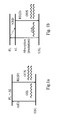
Figure 1 discloses two possible amplification schemes for an erbium doped amplifying optical fiber.Figure 1a discloses an amplification scheme for erbium using a 1480 nm pump laser. The lower horizontal line depicts the ground state energy level (GSL) of the erbium electrons. Upon pumping with the pump laser electrons are excited by means of laser energy absorption and move to a higher energy level following the left arrow of absorption (excitation) or A(E). The electrons are transferred to the pump level (PL) which is the same as the amplifying level (AL). Upon entry of an optical signal into the optical fiber, which optical signal is depicted by the single wave-line arrow on the left (optical input signal or OIS), the electrons in the amplifying level fall back to the ground state level while radiation emission or desexcitation (RE(D)) takes place following the right arrow. During this phase the optical signal is doubled as visible by the two wave-line arrows on the right (optical output signal or OUS). -
Figure 1b discloses an amplification scheme for erbium using a 980 nm pump laser. This scheme is slightly more complex and has an additional, third energy level. The lower horizontal line depicts the ground state energy level (GSL) of the erbium electrons. Upon pumping with the laser electrons are excited by means of laser energy absorption and move to a higher energy level following the left arrow of absorption (excitation) or A(E). The electrons are transferred to the pump level (PL) which is not the same, but higher than the amplifying level (AL). An additional step of non-radiative desexcitation (NRD) takes place wherein the energy difference between the pump level and the amplifying level is taken up by the matrix material of the nanoparticle and the electron is hence transferred from the pump level to the amplifying level. Upon entry of an optical signal into the optical fiber, which optical signal is depicted by the single wave-line arrow on the left (optical input signal or OIS), the electrons in the amplifying level fall back to the ground state level while radiation emission or desexcitation (RE(D)) takes place following the right arrow. During this phase the optical signal is doubled as visible by the two wave-line arrows on the right (optical output signal or OUS). -
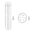
Figure 2a schematically shows a fiber according to the invention. The central core is depicted by a broken line and the black dots represent nanoparticles comprising rare earth ions; the central core is surrounded by the optical cladding.Figure 2b shows a cross-section of a single nanoparticle wherein the black dots are separate rare earth ions embedded in the matrix material of the nanoparticle - According to the present inventors it is necessary to improve the intrinsic efficiency of the process by which each rare earth ion absorbs the pump signal and transfers this to the excited state and following emits a photon which is similar to the incident optical signal while falling back into the ground state level.
- It is also required according to the present invention to adapt the optogeometrical parameters of the central core of the optical fiber as well as its doping characteristics, being the characteristics of the optical guidance medium, in order to maximize the overall gain per unit fiber length. The improvement of the efficiency by maximization of the gain and minimization of the pump power consumption for a given gain value is limited by the interdependence of several of the parameters. Consequently, even if the key parameters that influence the efficiency are known - for example rare earth ion concentration, rare earth ion dispersion and rare earth ion close chemical environment - it is not possible to achieve the maximum effect of each one of the parameters, because the are linked together. The solution of the present invention hence can be found in an optimal balance between these parameters as disclosed in claim 1.
- The incorporation of doping ions of rare earth element(s) in the matrix material of nanoparticles, wherein the solubility and dispersion of the doping ions in the matrix material of the nanoparticles is closely controlled, by respectively the concentration and distance of the doping ions, gives rise to the required properties.
- The doping ions concentration in the central core of the present amplifying optical fiber is equal to or higher then 0.01 wt%, preferably equal to or higher than 0.1 wt% and equal to or lower than 1 wt%, preferably equal to or lower than 0.2 wt.%
- The doping ions of the rare earth element are only located in the nanoparticles and not in the matrix of the central core of the optical fiber. This means that the doping ion concentration in the central core can be adapted by increasing the number of nanoparticles within the central core, increasing the doping ion concentration within each of the nanoparticles, or increasing the size of the nanoparticles or a combination thereof, depending on the application.
- It is of course possible to use several types of nanoparticles each having independently chosen doping ion concentration, matrix constitution and size.
- The doping ion concentration in the nanoparticles is between 0.1 wt. % and 20 wt. %, preferably between 0.5 wt. % and 15 wt%. This allows obtaining the required concentration of doping ions in the central core of the amplifying optical fiber according to the present invention.
- The two features of doping ion concentration and doping ion distance (also called the dispersion) can be most easily obtained in certain matrixes, for example matrixes having a certain level of aluminum, phosphorus, or calcium, depending on the requirements.
- In addition, the matrix of the nanoparticles is selected in such a manner as to ensure certain gain characteristics for the rare earth doping ions. The desired gain characteristics depend on the application, each application will have a specific need concerning the amplifying gain shape.
- For example, WDM applications will require wide amplifying band, while single channel amplification or laser applications will require intense and sharp band. The gain shape characteristics of a rare earth ion is governed by its close chemical environment within the central core of the optical fiber, so that controlling neighbor elements of the rare earth doping ions is important to fit the right gain shape. Some elements are known to widen the gain band associated to a specific rare earth, such as fluoride, aluminum, zirconium, and tellurium. Other elements are known to give rise to narrow band, such as sodium or phosphorus, while keeping high rare earth solubility property. Moreover, the rare earth near chemical environmental structure will have also a strong influence on band width. For example, amorphous disordered structures will favor band widening while crystalline phases or weakly disordered amorphous structures will favor sharp intense bands. Using rare earth incorporation into optical fiber by means of specific nanoparticles will allow a better tailoring of rare earth environment compared to a random doping process.
- A person skilled in the art will be able to select the most optimal matrix for the nanoparticles depending on the desired characteristics. The use of the present method for preparing the nanoparticles according to the present invention enables the constructing of nanoparticles having the matrix adapted to the application since the nanoparticles are synthesized before being incorporated into central core of the optical fiber.
- In addition, it is preferred that the matrix of the nanoparticles is selected in such a manner as to have a phonon energy favoring rare earth desexcitation by stimulated emission.
- In one embodiment of the present invention, related to a two-level amplifying scheme as depicted in
Figure 1a , the matrix material of the nanoparticles has a phonon energy that is lower than 20 % of the energy gap between the amplifying level and ground state level of the rare earth element during pumping, more preferably lower than 15%. For better efficiency of the desexcitation of the doping ions the matrix of the nanoparticles should have a phonon energy that is limited or restricted to a certain window. Outside this window, the efficiency will be decreased since energy will be lost due to transfer of energy from the amplifying level to the matrix network. Excited electrons will hence be lost for signal amplification and hence the efficiency is decreased. - In another embodiment of the present invention, related to a three-level amplifying scheme as depicted in
Figure 1b , the matrix material of the nanoparticles has a phonon energy of at least 25% of the energy gap between the pump level and the amplifying level of the rare earth element during pumping and at most 22 %, preferably 18.5% of the energy gap between the amplifying level and ground state level of the rare earth element during pumping. In this embodiment there is a minimum level of phonon energy required for the matrix material of the nanoparticles. Since the pump level and the amplifying level are not the same a certain transfer of energy is required towards the matrix material in order to transfer the electron from the pump level to the amplifying level. Since only an electron in the amplifying level can give rise to desexcitation and signal amplification. - It is desirable to limit the probability of other radiative and non-radiative fluorescence extinction processes in addition to the processes depicted in
Figure 1 . - Any other processes will significantly interfere with the amplification of the optical signal. A non-limitative list of examples of these processes are multiphonon relaxation, transfer to defects or impurities in the matrix material, ion-ion transfer (so-called cross-relaxation), ETU for Energy Transfer Up-conversion, excited state absorption. In an amplifying optical fiber, the measured undesirable fluorescence decay from the amplifying level is viewed as the sum of different phenomenon probabilities. Wmeas = Wrad + WMP + WCR + WET, wherein Wmeas is the measured fluorescence decay, Wrad is the probability of radiative desexcitation, WMP, WCR and WET are non-radiative desexcitation processes, respectively the probability of multiphonon relaxation, the probability of cross-relaxation and the probability of energy transfer to neighboring impurities and defects.
- A decrease of the amplifying process efficiency is mainly due to these types of non-radiative phenomena, which phenomena depend strongly on the vibration energy of the matrix of the nanoparticles, which vibration energy is quantified as energy quantum or phonon. The higher the matrix phonon energy is, the higher the probability for these processes to occur. In the frame of amplification, one have thus to find the right matrix phonon level. In this view, one can define a window in which matrix phonon energy should be restricted in order to benefit to amplification.
- For example, if we consider erbium amplification with a 980 nm pumping, the energy gap between rare earth pump and amplifying levels is around 4000 cm-1 and the energy gap between rare earth amplifying and ground state levels is around 6500 cm-1, so that NP matrix phonon energy should be comprised between 1000 and 1400 cm-1. more preferably between 1000 and 1200 cm-1. Silicate, phosphate, aluminate, or multi component matrixes including Si, P and Al oxides in thermodynamically stable composition will fit the required phonon energy level.
- Moreover, all desexcitation processes involving energy transfer between excited rare earth ions and defects or impurities (mainly OH) of the nanoparticles could be avoided or strictly limited due to the manufacturing process of the nanoparticles and their incorporation process within the central core of the optical fiber.
- It is an important aspect of the present invention, as mentioned already before, that the nanostructure of the nanoparticles is maintained during incorporation of the nanoparticles into the amplifying optical fiber according to the present invention. This means that the structure of the nanoparticle has to resist the high temperatures that are linked to the collapsing and fiber drawing processes. For example, the nanoparticle should be able to resist temperatures higher than 1800 °C or even 2000 °C. Such temperature dependence can be reached by correct selection of matrix material for the nanoparticles. Hence the nanoparticles should have a matrix material that is resistant to temperatures of at least 1800 °C, preferably at least 2000 °C. Non-limiting example of material that would be suitable as nanoparticle matrix material is alumina.
- One can also envisage other nanoparticle design, for example a core shell structure in which a nanoparticle is build up out of a core made of a core matrix material which core is surrounded by a shell which is made of a highly resistant matrix material. This dual structure allows getting highly resistant nanoparticles independent of the core matrix material of the nanoparticles. So, the nanoparticle matrix can be chosen to fit the right amplifying characteristics, even if this core matrix material of the nanoparticles is not able to resist to high temperatures. The nanoparticle resistance to high temperature is brought by the nanoparticle shell nature.
- The matrix material of the nanoparticles is alumina (Al2O3) or a combination of alumina (Al2O3) and phosphorus oxide (P2O5).
- In a preferred embodiment, the matrix material of the nanoparticles is amorphous. In order to optimize the fiber optical core transparency which is an important parameter, a low light scattering due to the presence of the nanoparticles in the central core should be ensured. If the nanoparticles have a different refractive index as the central core, light scattering will occur. In this view, the structure of the nanoparticle should be preferably amorphous since crystalline nanoparticles give higher light scattering. If crystalline nanoparticles are designed it is then important to finely define their optimum size, taking into account their refractive index and doping ion concentration.
- The rare earth content is the central core of the optical fiber can also be linked to the attenuation of rare earth ions at absorption peak expressed in dB/m. This peak should be between 2 and 20 dB/m.
- In an embodiment of the present invention, the silica-based matrix of the central core is doped with at least one element selected from the group, consisting of germanium, phosphorus, fluoride, boron and one or more combinations thereof. These doping elements can be used to increase or decrease the refractive index of the central core to the desired level.
- Preferably, the total concentration of alumina in the central core is equal to or lower than 4 wt. %, preferably equal to or lower than 3.5 wt. % based on the total weight of the central core. This limit has to do with the fact that alumina from the nanoparticles can give rise to a high refractive index difference with the outer cladding. In the case of too high a concentration of alumina light scattering will increase which is undesirable.
- In a preferred embodiment, the rare earth element is selected from the group, consisting of erbium, ytterbium, thulium, or a combination of these elements, preferably erbium or a combination of erbium and ytterbium.
- It is possible that additional elements are present in the matrix of the nanoparticles in order to improve several matrix properties, such as for example solubility of the rare earth doping ions. Examples of such additional elements are calcium, aluminum, sodium, or phosphorus.
- Particularly, if alumina is used as a major part of the matrix material of the nanoparticle the rare earth solubility is good.
- As the number of rare earth ions per nanoparticles can be controlled, for a given nanoparticle size, the final rare earth concentration within the central core or the optical fiber will be driven by the concentration of the nanoparticles in the fiber core, that is to say, the number of nanoparticles incorporated during the doping step. The total rare earth concentration within the central core of the optical fiber will be determined by a skilled person according to the application and can be reached by adjusting either the concentration of nanoparticles in the central core (=[NP]core) or the rare earth doping ion concentration in each of the nanoparticles ([RE]NP). The constant parameter is the total rare earth concentration in the core, given by the product [NP]core X [RE]NP. As an example, in the case of high input signal power, the relation between [NP]core and [RE]NP will be adjusted to ensure 100% rare earth inversion and minimum pump power consuming to reach a given output power signal. In this view, one could reach the desired rare earth concentration within the central core of the optical fiber either by preferring high [NP]core and low [RE]NP, or otherwise low [NP]core and high [RE]NP.
- Preferably, the optical fiber has background attenuation losses equal to or lower than 4 dB/km at 1200 nm, preferably equal to or lower than 2 dB/km at 1200 nm.
- Preferably, the size of the nanoparticles is equal to or lower than 100 nm, preferably equal to or lower than 50 nm, more preferably equal to or lower than 20 nm. If the refractive index of the nanoparticles is close to the refractive index of the central core, the size of the nanoparticles can be as high as several tens of nanometers due to less light scattering. However, if the refractive indexes of the nanoparticles and the central core are significantly different, the size of the nanoparticles should be lower than 20 nm due to more light scattering.
- The size of the nanoparticles is preferably at least 2 nm, more preferably at least 5 nm.
- According to the present invention, the optical guidance structure can be optimized independently from the gain performance, since the matrix of the nanoparticles (responsible for gain performance) can be adapted independently from the matrix of the central core (responsible for optical guidance structure). Thus it is possible to adapt the optogeometrical parameters to optimize amplifier efficiency, for example by selecting a certain cut-off wavelength and refractive index of the central core, without affecting the optical response of rare earth doping ions.
- The transparency of the central core of the optical fiber in the application wavelength window is an important parameter for the overall gain that can be reached by the amplifying medium. In order to obtain such transparency the attenuation threshold of the optical fibers should be as low as possible. In doping processes according to the prior art without the use of nanoparticles the optical performances and the central core matrix composition are strongly linked, making it difficult to adapt the central core optical transparency independently from the rare earth close chemical environment. For example, WDM doped fibers for EDFAs will necessitate a high aluminum concentration to ensure sufficient aluminum atoms in the erbium environment. However, this results in loss in transparency and hence loss in efficiency, which is undesirable.
- An optical fiber is conventionally composed of (i) an optical core, having the function of transmitting and optionally amplifying an optical signal, and (ii) an optical cladding, having the function of confining the optical signal in the core. For this purpose, the refractive indexes of the core (nc) and of the cladding (ng) are such that nc > ng. As is well known in the art, the propagation of an optical signal in a single-mode optical fiber is broken down into a fundamental mode (known as LP01) guided in the core, and into secondary modes guided over a certain radius in the core-cladding assembly.
- For optical fibers, the refractive index profile is generally set forth in terms of the difference in refractive index value between two points on the graph of the function associating the refractive index with the radius of the fiber. The external cladding functions as an optical cladding and has a substantially constant refractive index; this optical cladding is generally composed of pure silica but can also contain one or more dopants. The optical fiber refractive index profile is referred to as a "step" profile, a "trapezoidal" profile, or a "triangular" profile for graphs having the respective shapes of a step, a trapezoid, or a triangle. These curves are generally representative of the theoretical or reference index profile (i.e., set profile) of the fiber. Fiber manufacturing constraints may lead to a slightly different profile in the actual fiber. The amplifying optical fiber according to the present invention preferably has a step index refractive index profile.
- The invention proposes an amplifying optical fiber, including, from the center toward the periphery, a central core and an external optical cladding. The central core has a radius r, preferably between 3 and 6 µm, and a positive refractive index difference Δ, preferably between 6 x 10⁻³ and 20 x 10-3 with the external optical cladding. The fiber according to this invention further preferably has a mode field diameter (MFD) between 4 and 7 µm at a wavelength of 1550 nm and a numerical aperture between 0.16 and 0.20 nm, preferably between 0.17 to 0.19 to obtain an optimal pump confinement. The present amplifying optical fiber preferably has a cut-off wavelength (λc) below 1300 nm, preferably below 1200 nm, in order to obtain high pump confinement.
- The pump confinement or pump conversion efficiency (PCE) is preferably above 90 % at a pumping wavelength of 980 nm.
- The signal confinement at 1550 nm should be at least 70 % and is defined as the overlap between the erbium emission and the signal mode field.
- Preferably, an optical fiber is designed taking into account a) the rare earth doping ions efficiency, through control of the chemical environment and concentration of the doping ions; b) optogeometrical parameters of the optical fiber independently; c) a high transparency of the matrix of the central core of the optical fiber in the application wavelength window.
- The present invention also relates to the use of an amplifying optical fiber according to the present invention in an optical amplifier or an optical laser.
- In addition, the present invention relates to an optical amplifier or an optical laser comprising at least a length of an amplifying optical fiber according to the present invention.
- Preferably, an optical amplifier comprising a part of a fiber according to the invention can be used in a high power regime to reach 23 dBm signal output power with a pump power lower than 550 mW, or 25 dBm signal output power with a pump power lower than 1000 mW, or 27 dBm signal output power with a pump power lower than 1500 mW.
- The present invention also relates to a method for preparing a suspension of nanoparticles, which nanoparticles are composed of a matrix material comprising doping ions of at least one rare earth element.
-
US 2003/0175003 of the present inventors mentions a method of preparing nanoparticles by means of either a laser ablation process or a modified sol-gel process. However, these processes cannot produce the nanoparticles having the doping ion distance as required by the present invention. Therefore, the invention proposes a different method of producing nanoparticles. This process uses so-called soft chemistry starting from inorganic salt precursors, comprising the steps of: - a) Providing at least one compound comprising at least one ion of a rare earth element;
- b) Providing at least one compound comprising at least one ion to form the matrix material of the nanoparticle;
- c) Adding the compounds obtained in step a) and step b) to an aqueous solution having a pH in the range of 3-12, preferably between 6 and 10 under stirring in order to obtain the suspension of nanoparticles.
-
Figure 3a shows this process graphically. In step a) the rare earth salt is provided. In step b) the compound is provided which will give rise to the matrix of the nanoparticle. Preferably, the ratio of the amount of compound a) to the amount of compound b) is 1:10 to 300. - In a preferred embodiment of the present method for preparing a suspension of nanoparticles, the at least one compound in step a) is selected from the group consisting of erbium salts, preferably erbium acetate, erbium nitrate, erbium acetylacetonate, erbium chloride and one or more combinations thereof.
- In another preferred embodiment of the present method for preparing a suspension of nanoparticles, the at least one compound in step b) is selected from the group consisting of aluminum salts and phosphorus salts or a combination thereof, preferably from the group consisting of aluminum nitrate and phosphorus trichloride oxide and a combination thereof.
- In another preferred embodiment of the present method for preparing a suspension of nanoparticles, step c) is carried out at a temperature between 10 and 50°C, preferably between 20 and 40 °C.
- In addition, the present invention relates to a method for manufacturing an amplifying optical fiber according to the present invention.
US 2003/0175003 of the present inventors mentions a method of manufacturing an amplifying optical fiber. However, the present invention relates to a novel process including a heating step to strengthen the structure of the nanoparticles before the hollow tube comprising the nanoparticles is sintered and collapsed. - The method according to the present invention comprises the steps according to claim 14 and is depicted in
Figure 3b - In order for the designed nanoparticles to be really efficient in the specified optical performances, the matrix of the nanoparticles has to be preserved as a nanostructure within the fiber core an thus resist to stress and temperature conditions experienced during e.g. MCVD preform manufacturing process and fiber drawing. This can be obtained by the thermal treatment of step IV), realized after their incorporation step through impregnation and before the steps of layer sintering and preform collapsing. This step can be carried out at temperatures equal to or higher than e.g. 500 °C, equal to or higher than e.g. 800 °C, equal to or higher than e.g. 1000 °C, or equal to or higher than e.g. 1200 °C.
- For example, it is known that one can transform alumina into more thermally resistant phases by an appropriated treatment at temperatures equal to or higher than 1000°C.
- The present invention is furthermore explained by the following, non-limiting example give for explanation purposes only.
- An erbium doped optical fiber for high efficiency amplification in the C-band is obtained by the following method.
- Firstly, nanoparticles comprising erbium doping ions are prepared. Aluminum nitrate and erbium nitrate are co-precipitated in an aqueous solution whose pH is maintained equal to 9 using sodium hydroxide.
- The erbium salt concentration is 3 mmoles/I and the molar ratio between aluminum salt and erbium salt is around 200, in order to guarantee the required dispersion of erbium doping ions in the alumina matrix of the nanoparticle. This should lead to erbium ions having a chemical environment able to reach the expected spectroscopic characteristics. The size of the precipitated nanoparticles is approximately 25 nm.
- After precipitation and nanoparticle washing, pH is adjusted to 6 by addition of hydrochloric acid. A stable aqueous suspension of Al/Er co-doped nanoparticles with a known erbium concentration is obtained. This suspension is then used to impregnate the porous silica-based central core layer of a hollow silica tube obtained via MCVD process. For this purpose the hollow tube is brought into an upright position and the suspension is poured into the hollow tube.
- The refractive index difference between central core and cladding has been adjusted to 13 x 10-3 by using germanium in the matrix of the central core. After the impregnation, excess of the suspension is removed from the hollow tube and the tube is dried and thermally treated at a temperature of approximately 1100 °C during 1 hour in order to dry and strengthen the nanoparticle structure within the central core. After that the resulting doped core layer is sintered. The doped tube is then collapsed at a temperature of approximately 2200 °C to give the primary preform which is then sleeved to adapt the ratio of the diameter of the central core and the diameter of the optical cladding. The final preform is finally drawn into an optical fiber using a standard drawing technique.
- An erbium doped fiber is obtained having an erbium attenuation of 6 dB/m at 1528 nm as measured by the maximum absorption, which corresponds approximately to 0.036 wt. % of erbium in the total core weight. The optical fiber has a cut-off wavelength of 1150 nm, a refractive index difference with the optical cladding op 13 x 10-3, a numerical aperture of 0.19, an MFD at 1550 nm of 5.6 micrometers and a central core diameter of 5 micrometer. The optical fiber presents low losses of 1.6 dB/km at 1220 nm. The pump confinement at 980 nm is equal to 90 % and the signal confinement, is 70%.
- The fiber presents high efficiency at high input signal power and can be used as high power / low gain EDFA extender in the WDM C-band. The fiber allows saving up to 10% of pump power at 25dBm output signal power. The fiber can also be used to reach unprecedented 26 dBm signal output power in a dual pump amplifying scheme involving two 750 mW 980 nm laser pumps.
- The present invention is further characterized by the appended claims.
Claims (14)
- An amplifying optical fiber having a central core and an optical cladding surrounding the central core, wherein the central core is based on a silica matrix comprising nanoparticles, which nanoparticles are composed of a matrix material comprising doping ions of at least one rare earth element and which matrix material is alumina (Al2O3) or a combination of alumina (Al2O3) and phosphorus oxide (P2O5), wherein the concentration of the doping ions is between 0.01 wt. % and 1 wt. %, preferably between 0.01 wt. % and 0.2 wt. % of the total weight of the central core and wherein the distance between the doping ions in the nanoparticles is at least 0.4 nanometers and wherein the concentration of doping ions in the nanoparticle is between 0.1 and 20 wt. % of the total weight of the nanoparticle.
- An amplifying optical fiber according to claim 1, wherein the concentration of doping ions in the nanoparticle is between 0.5 and 15 wt. % of the total weight of the nanoparticle.
- An amplifying optical fiber according to any one of the preceding claims, wherein the matrix material of the nanoparticles has a phonon energy that is lower than 20 % of the energy gap between the amplifying level and ground state level of the rare earth element during pumping, more preferably lower than 15 % of the energy gap.
- An amplifying optical fiber according to any one of the preceding claims, wherein the matrix material of the nanoparticles has a phonon energy of at least 25 % of the energy gap between the pump level and the amplifying level of the rare earth element during pumping and at most 22 %, preferably 18.5 % of the energy gap between the amplifying level and ground state level of the rare earth element during pumping.
- An amplifying optical fiber according to any one of the preceding claims, wherein the matrix material of the nanoparticles is amorphous.
- An amplifying optical fiber according to any one of the preceding claims, wherein the silica-based matrix of the central core is doped with at least one element selected from the group, consisting of germanium, phosphorus, fluoride, boron and one or more combinations thereof.
- An amplifying optical fiber according to any one of the preceding claims, wherein the total concentration of alumina in the central core is equal to or lower than 4 wt. %, preferably equal to or lower than 3.5 wt. % based on the total weight of the central core.
- An amplifying optical fiber according to any one of the preceding claims, wherein the rare earth element is selected from the group, consisting of erbium, ytterbium, thulium, and a combination of these elements, preferably erbium with ytterbium.
- An amplifying optical fiber according to any one of the preceding claims, wherein the optical fiber has background attenuation losses equal to or lower than 4 dB/km at 1200 nm, preferably equal to or lower than 2 dB/km at 1200 nm.
- An amplifying optical fiber according to any one of the preceding claims, wherein the size of the nanoparticles is equal to or lower than 100 nm, preferably equal to or lower than 50 nm, more preferably equal to or lower than 20 nm.
- Use of an amplifying optical fiber according to any one of the preceding claims in an optical amplifier or an optical laser.
- Optical amplifier comprising at least a length of an amplifying optical fiber according to any one of the claims 1-10.
- Optical laser comprising at least one portion of a fiber according to any one of the claims 1-10 and 12.
- Method for manufacturing an amplifying optical fiber according to any of claims 1-10, the method comprising the following steps:I) preparing a suspension of nanoparticles composed of a matrix material comprising doping ions of at least one rare earth element and which matrix material is alumina (Al2O3) or a combination of alumina (Al2O3) and phosphorus oxide (P2O5)II) Providing a hollow silica-based tube having an inner porous layer prepared by a chemical vapor deposition (CVD) process;III) Impregnating the inner porous layer of the hollow tube obtained in step II) with the suspension obtained in step I);IV) Applying heat to the doped inner porous layer obtained in step III) to eliminate residual water and strengthen the nanoparticles;V) Vitrifying and collapsing the hollow tube obtained in step IV) to obtain an optical preform;VI) Optionally sleeving or overcladding the optical preform obtained in step V) to obtain an optical preform with modified ratio of central core diameter over optical cladding diameter;VII) drawing the optical preform obtained in step V) or step VI) to obtain an optical fiber having a central core and an optical cladding surrounding the central core, wherein the central core is based on a silica matrix comprising nanoparticles, which nanoparticles are composed of a matrix material comprising doping ions of at least one rare earth element and which matrix material is alumina (Al2O3) or a combination of alumina (Al2O3) and phosphorus oxide (P2O5), wherein the concentration of the ions is between 0.01 wt. % and 1 wt. %, preferably between 0.01 wt. % and 0.2 wt. % of the total weight of the central core and wherein the distance between the ions in the particles is at least 0.4 nanometers and wherein the concentration of doping ions in the nanoparticle is between 0.1 and 20 wt. % of the total weight of the nanoparticle.
Priority Applications (8)
| Application Number | Priority Date | Filing Date | Title |
|---|---|---|---|
| DK08291059.7T DK2187486T3 (en) | 2008-11-12 | 2008-11-12 | Reinforcing optical fiber and method of manufacture |
| ES08291059.7T ES2487443T3 (en) | 2008-11-12 | 2008-11-12 | Fiber optic amplification and procedure to manufacture it |
| EP12190157.3A EP2565997A3 (en) | 2008-11-12 | 2008-11-12 | Amplifying optical fiber and method of manufacturing. |
| EP08291059.7A EP2187486B1 (en) | 2008-11-12 | 2008-11-12 | Amplifying optical fiber and method of manufacturing |
| JP2009258759A JP5670043B2 (en) | 2008-11-12 | 2009-11-12 | Amplifying optical fiber and manufacturing method |
| US12/617,316 US8259389B2 (en) | 2008-11-12 | 2009-11-12 | Amplifying optical fiber and method of manufacturing |
| CN200910208378A CN101782667A (en) | 2008-11-12 | 2009-11-12 | Amplifying optical fiber and method of manufacturing |
| KR1020090109362A KR20100053477A (en) | 2008-11-12 | 2009-11-12 | Amplifying optical fiber and method of manufacturing |
Applications Claiming Priority (1)
| Application Number | Priority Date | Filing Date | Title |
|---|---|---|---|
| EP08291059.7A EP2187486B1 (en) | 2008-11-12 | 2008-11-12 | Amplifying optical fiber and method of manufacturing |
Related Child Applications (1)
| Application Number | Title | Priority Date | Filing Date |
|---|---|---|---|
| EP12190157.3A Division-Into EP2565997A3 (en) | 2008-11-12 | 2008-11-12 | Amplifying optical fiber and method of manufacturing. |
Publications (2)
| Publication Number | Publication Date |
|---|---|
| EP2187486A1 EP2187486A1 (en) | 2010-05-19 |
| EP2187486B1 true EP2187486B1 (en) | 2014-04-23 |
Family
ID=40586198
Family Applications (2)
| Application Number | Title | Priority Date | Filing Date |
|---|---|---|---|
| EP12190157.3A Withdrawn EP2565997A3 (en) | 2008-11-12 | 2008-11-12 | Amplifying optical fiber and method of manufacturing. |
| EP08291059.7A Not-in-force EP2187486B1 (en) | 2008-11-12 | 2008-11-12 | Amplifying optical fiber and method of manufacturing |
Family Applications Before (1)
| Application Number | Title | Priority Date | Filing Date |
|---|---|---|---|
| EP12190157.3A Withdrawn EP2565997A3 (en) | 2008-11-12 | 2008-11-12 | Amplifying optical fiber and method of manufacturing. |
Country Status (7)
| Country | Link |
|---|---|
| US (1) | US8259389B2 (en) |
| EP (2) | EP2565997A3 (en) |
| JP (1) | JP5670043B2 (en) |
| KR (1) | KR20100053477A (en) |
| CN (1) | CN101782667A (en) |
| DK (1) | DK2187486T3 (en) |
| ES (1) | ES2487443T3 (en) |
Families Citing this family (81)
| Publication number | Priority date | Publication date | Assignee | Title |
|---|---|---|---|---|
| US8031997B2 (en) | 2007-11-09 | 2011-10-04 | Draka Comteq, B.V. | Reduced-diameter, easy-access loose tube cable |
| BRPI0819166B1 (en) | 2007-11-09 | 2019-03-06 | Draka Comteq, B.V. | OPTICAL FIBER, AND OPTICAL BOX |
| US8145026B2 (en) | 2007-11-09 | 2012-03-27 | Draka Comteq, B.V. | Reduced-size flat drop cable |
| US8081853B2 (en) | 2007-11-09 | 2011-12-20 | Draka Comteq, B.V. | Single-fiber drop cables for MDU deployments |
| US8041168B2 (en) | 2007-11-09 | 2011-10-18 | Draka Comteq, B.V. | Reduced-diameter ribbon cables with high-performance optical fiber |
| US8041167B2 (en) * | 2007-11-09 | 2011-10-18 | Draka Comteq, B.V. | Optical-fiber loose tube cables |
| US8165439B2 (en) | 2007-11-09 | 2012-04-24 | Draka Comteq, B.V. | ADSS cables with high-performance optical fiber |
| US8467650B2 (en) | 2007-11-09 | 2013-06-18 | Draka Comteq, B.V. | High-fiber-density optical-fiber cable |
| DK2344911T3 (en) | 2008-11-07 | 2015-07-13 | Draka Comteq Bv | Reduced diameter optical fiber |
| ES2487443T3 (en) | 2008-11-12 | 2014-08-20 | Draka Comteq B.V. | Fiber optic amplification and procedure to manufacture it |
| FR2939246B1 (en) * | 2008-12-02 | 2010-12-24 | Draka Comteq France | AMPLIFIER OPTICAL FIBER AND METHOD OF MANUFACTURE |
| FR2939522B1 (en) * | 2008-12-08 | 2011-02-11 | Draka Comteq France | OPTICAL FIBER AMPLIFIER RESISTANT TO IONIZING RADIATION |
| FR2939911B1 (en) * | 2008-12-12 | 2011-04-08 | Draka Comteq France | SOLDERED OPTICAL FIBER, TELECOMMUNICATION CABLE COMPRISING MULTIPLE OPTICAL FIBERS AND METHOD FOR MANUFACTURING SUCH A FIBER |
| NL1036343C2 (en) * | 2008-12-19 | 2010-06-22 | Draka Comteq Bv | METHOD AND APPARATUS FOR MANUFACTURING AN OPTICAL FORM. |
| ES2573329T3 (en) | 2008-12-30 | 2016-06-07 | Draka Comteq B.V. | Fiber optic cable comprising a perforated water blocking element |
| US8314408B2 (en) | 2008-12-31 | 2012-11-20 | Draka Comteq, B.V. | UVLED apparatus for curing glass-fiber coatings |
| FR2941539B1 (en) * | 2009-01-23 | 2011-02-25 | Draka Comteq France | OPTICAL FIBER MONOMODE |
| FR2941540B1 (en) * | 2009-01-27 | 2011-05-06 | Draka Comteq France | MONOMODE OPTICAL FIBER HAVING ENHANCED EFFECTIVE SURFACE |
| FR2941541B1 (en) * | 2009-01-27 | 2011-02-25 | Draka Comteq France | OPTICAL FIBER MONOMODE |
| US8489219B1 (en) | 2009-01-30 | 2013-07-16 | Draka Comteq B.V. | Process for making loose buffer tubes having controlled excess fiber length and reduced post-extrusion shrinkage |
| US9360647B2 (en) * | 2009-02-06 | 2016-06-07 | Draka Comteq, B.V. | Central-tube cable with high-conductivity conductors encapsulated with high-dielectric-strength insulation |
| FR2942571B1 (en) * | 2009-02-20 | 2011-02-25 | Draka Comteq France | AMPLIFIER OPTICAL FIBER COMPRISING NANOSTRUCTURES |
| FR2942551B1 (en) * | 2009-02-23 | 2011-07-15 | Draka Comteq France | CABLE COMPRISING ELEMENTS TO BE EXTRACTED, METHOD OF EXTRACTING THESE ELEMENTS AND METHOD OF MANUFACTURING THE SAME |
| US8625944B1 (en) | 2009-05-13 | 2014-01-07 | Draka Comteq, B.V. | Low-shrink reduced-diameter buffer tubes |
| US8625945B1 (en) | 2009-05-13 | 2014-01-07 | Draka Comteq, B.V. | Low-shrink reduced-diameter dry buffer tubes |
| FR2946436B1 (en) * | 2009-06-05 | 2011-12-09 | Draka Comteq France | MULTIMODE OPTICAL FIBER WITH LARGE BANDWIDTH WITH AN OPTIMIZED HEAT-SLEEVE INTERFACE |
| US20110026889A1 (en) * | 2009-07-31 | 2011-02-03 | Draka Comteq B.V. | Tight-Buffered Optical Fiber Unit Having Improved Accessibility |
| FR2953029B1 (en) | 2009-11-25 | 2011-11-18 | Draka Comteq France | MULTIMODE OPTICAL FIBER WITH LARGE BANDWIDTH WITH AN OPTIMIZED HEAT-SLEEVE INTERFACE |
| FR2953605B1 (en) | 2009-12-03 | 2011-12-16 | Draka Comteq France | MULTIMODE OPTICAL FIBER WITH BROAD BANDWIDTH AND LOW BENDBACK LOSSES |
| US9014525B2 (en) | 2009-09-09 | 2015-04-21 | Draka Comteq, B.V. | Trench-assisted multimode optical fiber |
| FR2949870B1 (en) | 2009-09-09 | 2011-12-16 | Draka Compteq France | MULTIMODE OPTICAL FIBER HAVING IMPROVED BENDING LOSSES |
| FR2953030B1 (en) | 2009-11-25 | 2011-11-18 | Draka Comteq France | MULTIMODE OPTICAL FIBER WITH LARGE BANDWIDTH WITH AN OPTIMIZED HEAT-SLEEVE INTERFACE |
| FR2957153B1 (en) | 2010-03-02 | 2012-08-10 | Draka Comteq France | MULTIMODE OPTICAL FIBER WITH BROAD BANDWIDTH AND LOW BENDBACK LOSSES |
| FR2953606B1 (en) | 2009-12-03 | 2012-04-27 | Draka Comteq France | MULTIMODE OPTICAL FIBER WITH BROAD BANDWIDTH AND LOW BENDBACK LOSSES |
| US8306380B2 (en) * | 2009-09-14 | 2012-11-06 | Draka Comteq, B.V. | Methods and devices for cable insertion into latched-duct conduit |
| FR2950156B1 (en) | 2009-09-17 | 2011-11-18 | Draka Comteq France | MULTIMODE OPTIC FIBER |
| FR2950443B1 (en) * | 2009-09-22 | 2011-11-18 | Draka Comteq France | OPTICAL FIBER FOR SUM FREQUENCY GENERATION AND METHOD FOR MANUFACTURING THE SAME |
| US8805143B2 (en) * | 2009-10-19 | 2014-08-12 | Draka Comteq, B.V. | Optical-fiber cable having high fiber count and high fiber density |
| FR2952634B1 (en) | 2009-11-13 | 2011-12-16 | Draka Comteq France | RARE EARTH DOPED SILICA FIBER WITH LOW DIGITAL OPENING |
| US9042693B2 (en) | 2010-01-20 | 2015-05-26 | Draka Comteq, B.V. | Water-soluble water-blocking element |
| EP2352047B1 (en) * | 2010-02-01 | 2019-09-25 | Draka Comteq B.V. | Non-zero dispersion shifted optical fiber having a large effective area |
| EP3399357A1 (en) * | 2010-02-01 | 2018-11-07 | Draka Comteq B.V. | Non-zero dispersion shifted optical fiber having a short cutoff wavelength |
| EP2369379B1 (en) * | 2010-03-17 | 2015-05-06 | Draka Comteq B.V. | Fibre optique monomode ayant des pertes par courbures réduites |
| US8693830B2 (en) | 2010-04-28 | 2014-04-08 | Draka Comteq, B.V. | Data-center cable |
| US8855454B2 (en) | 2010-05-03 | 2014-10-07 | Draka Comteq, B.V. | Bundled fiber optic cables |
| DK2388239T3 (en) | 2010-05-20 | 2017-04-24 | Draka Comteq Bv | Curing apparatus using angled UV LEDs |
| US8625947B1 (en) | 2010-05-28 | 2014-01-07 | Draka Comteq, B.V. | Low-smoke and flame-retardant fiber optic cables |
| US8871311B2 (en) | 2010-06-03 | 2014-10-28 | Draka Comteq, B.V. | Curing method employing UV sources that emit differing ranges of UV radiation |
| FR2962230B1 (en) | 2010-07-02 | 2012-07-27 | Draka Comteq France | OPTICAL FIBER MONOMODE |
| US8682123B2 (en) | 2010-07-15 | 2014-03-25 | Draka Comteq, B.V. | Adhesively coupled optical fibers and enclosing tape |
| DK2418183T3 (en) | 2010-08-10 | 2018-11-12 | Draka Comteq Bv | Method of curing coated glass fibers which provides increased UVLED intensity |
| US8571369B2 (en) | 2010-09-03 | 2013-10-29 | Draka Comteq B.V. | Optical-fiber module having improved accessibility |
| FR2966256B1 (en) | 2010-10-18 | 2012-11-16 | Draka Comteq France | MULTIMODE OPTICAL FIBER INSENSITIVE TO LOSSES BY |
| US8824845B1 (en) | 2010-12-03 | 2014-09-02 | Draka Comteq, B.V. | Buffer tubes having reduced stress whitening |
| FR2968775B1 (en) | 2010-12-10 | 2012-12-21 | Draka Comteq France | DOPED OPTICAL FIBER IN RARE EARTHS HAVING LOW INTERACTIONS BETWEEN THE DOPING ELEMENTS |
| KR101188344B1 (en) * | 2011-01-14 | 2012-10-05 | 광주과학기술원 | An optical fiber and coreless optical fiber having a cladding layer doped with metal nano particles, and manufacturing method of the same |
| DK2482106T5 (en) | 2011-01-31 | 2014-09-22 | Draka Comteq Bv | Multi-mode fiber |
| FR2971061B1 (en) | 2011-01-31 | 2013-02-08 | Draka Comteq France | BROAD BANDWIDTH OPTICAL FIBER WITH LOW CURB LOSSES |
| EP2678728B1 (en) | 2011-02-21 | 2018-04-18 | Draka Comteq B.V. | Optical-fiber interconnect cable |
| EP2495589A1 (en) | 2011-03-04 | 2012-09-05 | Draka Comteq B.V. | Rare earth doped amplifying optical fiber for compact devices and method of manufacturing thereof |
| EP2503368A1 (en) | 2011-03-24 | 2012-09-26 | Draka Comteq B.V. | Multimode optical fiber with improved bend resistance |
| EP2506044A1 (en) | 2011-03-29 | 2012-10-03 | Draka Comteq B.V. | Multimode optical fiber |
| EP2518546B1 (en) | 2011-04-27 | 2018-06-20 | Draka Comteq B.V. | High-bandwidth, radiation-resistant multimode optical fiber |
| ES2438173T3 (en) | 2011-05-27 | 2014-01-16 | Draka Comteq Bv | Single mode fiber optic |
| DK2533082T3 (en) | 2011-06-09 | 2014-03-24 | Draka Comteq Bv | Optical single-mode fiber |
| DK2541292T3 (en) | 2011-07-01 | 2014-12-01 | Draka Comteq Bv | A multimode optical fiber |
| EP2584340A1 (en) | 2011-10-20 | 2013-04-24 | Draka Comteq BV | Hydrogen sensing fiber and hydrogen sensor |
| NL2007831C2 (en) | 2011-11-21 | 2013-05-23 | Draka Comteq Bv | Apparatus and method for carrying out a pcvd deposition process. |
| US8929701B2 (en) | 2012-02-15 | 2015-01-06 | Draka Comteq, B.V. | Loose-tube optical-fiber cable |
| WO2013160714A1 (en) | 2012-04-27 | 2013-10-31 | Draka Comteq Bv | Hybrid single and multimode optical fiber for a home network |
| US9093815B2 (en) | 2012-08-29 | 2015-07-28 | Ofs Fitel, Llc | Optical fiber amplifier including rare-earth-doped cladding region |
| US9188754B1 (en) | 2013-03-15 | 2015-11-17 | Draka Comteq, B.V. | Method for manufacturing an optical-fiber buffer tube |
| NL2011075C2 (en) | 2013-07-01 | 2015-01-05 | Draka Comteq Bv | Pcvd process with removal of substrate tube. |
| GB2521156A (en) * | 2013-12-10 | 2015-06-17 | Fibercore Ltd | Optical transmission |
| CN105899982B (en) * | 2013-12-20 | 2019-11-22 | 德拉克通信科技公司 | Show the single mode optical fiber with trapezoidal fibre core that loss reduces |
| CN104556674B (en) * | 2015-02-03 | 2017-03-08 | 中国电子科技集团公司第四十六研究所 | A kind of preparation method of rare earth ion co-doped fiber prefabricated rods |
| KR101807835B1 (en) | 2015-08-26 | 2018-01-18 | 대한광통신 주식회사 | A method and a apparatus for manufacturing optical fiber with large caliber |
| US11043785B2 (en) * | 2016-10-14 | 2021-06-22 | The Government Of The United States Of America, As Represented By The Secretary Of The Navy | Nanoparticle doping for lasers and amplifiers operating at eye-safer wavelengths, and/or exhibiting reduced Stimulated Brillouin Scattering |
| CN109870830B (en) * | 2017-12-04 | 2021-07-27 | 上海飞博激光科技有限公司 | Element for decoherence of light beam |
| DK3729151T3 (en) | 2017-12-21 | 2022-07-11 | Draka Comteq France | Singlemode fiber insensitive to bending loss, with a low trench and corresponding optical system |
| TWI643166B (en) * | 2018-01-23 | 2018-12-01 | 巨晰光纖股份有限公司 | Optical fiber with image compensation (1) |
Family Cites Families (82)
| Publication number | Priority date | Publication date | Assignee | Title |
|---|---|---|---|---|
| US4838643A (en) | 1988-03-23 | 1989-06-13 | Alcatel Na, Inc. | Single mode bend insensitive fiber for use in fiber optic guidance applications |
| US5574816A (en) | 1995-01-24 | 1996-11-12 | Alcatel Na Cable Sytems, Inc. | Polypropylene-polyethylene copolymer buffer tubes for optical fiber cables and method for making the same |
| US5717805A (en) | 1996-06-12 | 1998-02-10 | Alcatel Na Cable Systems, Inc. | Stress concentrations in an optical fiber ribbon to facilitate separation of ribbon matrix material |
| US7322122B2 (en) | 1997-01-15 | 2008-01-29 | Draka Comteq B.V. | Method and apparatus for curing a fiber having at least two fiber coating curing stages |
| FR2760540B1 (en) | 1997-03-10 | 1999-04-16 | Alsthom Cge Alcatel | OPTICAL FIBER CABLE TIGHTENED IN SHEATH |
| US5911023A (en) | 1997-07-10 | 1999-06-08 | Alcatel Alsthom Compagnie Generale D'electricite | Polyolefin materials suitable for optical fiber cable components |
| US6066397A (en) | 1998-03-31 | 2000-05-23 | Alcatel | Polypropylene filler rods for optical fiber communications cables |
| US6175677B1 (en) | 1998-04-17 | 2001-01-16 | Alcatel | Optical fiber multi-ribbon and method for making the same |
| US6085009A (en) | 1998-05-12 | 2000-07-04 | Alcatel | Water blocking gels compatible with polyolefin optical fiber cable buffer tubes and cables made therewith |
| US6215931B1 (en) | 1999-01-26 | 2001-04-10 | Alcatel | Flexible thermoplastic polyolefin elastomers for buffering transmission elements in a telecommunications cable |
| US6134363A (en) | 1999-02-18 | 2000-10-17 | Alcatel | Method for accessing optical fibers in the midspan region of an optical fiber cable |
| US7094361B2 (en) * | 1999-03-19 | 2006-08-22 | Rutgers, The State University | Optically transparent nanocomposite materials |
| US6381390B1 (en) | 1999-04-06 | 2002-04-30 | Alcatel | Color-coded optical fiber ribbon and die for making the same |
| US6181857B1 (en) | 1999-05-12 | 2001-01-30 | Alcatel | Method for accessing optical fibers contained in a sheath |
| US6314224B1 (en) | 1999-06-18 | 2001-11-06 | Alcatel | Thick-walled cable jacket with non-circular cavity cross section |
| US6334016B1 (en) | 1999-06-30 | 2001-12-25 | Alcatel | Optical fiber ribbon matrix material having optimal handling characteristics |
| US6321012B1 (en) | 1999-08-30 | 2001-11-20 | Alcatel | Optical fiber having water swellable material for identifying grouping of fiber groups |
| US6493491B1 (en) | 1999-09-28 | 2002-12-10 | Alcatel | Optical drop cable for aerial installation |
| US6597496B1 (en) * | 1999-10-25 | 2003-07-22 | The Board Of Trustees Of The University Of Illinois | Silicon nanoparticle stimulated emission devices |
| US6321014B1 (en) | 1999-11-01 | 2001-11-20 | Alcatel | Method for manufacturing optical fiber ribbon |
| FR2809499B1 (en) | 2000-05-29 | 2003-10-03 | Cit Alcatel | PROTECTIVE SKIN FOR OPTICAL FIBERS |
| US6603908B2 (en) | 2000-08-04 | 2003-08-05 | Alcatel | Buffer tube that results in easy access to and low attenuation of fibers disposed within buffer tube |
| US6922515B2 (en) | 2000-12-20 | 2005-07-26 | Alcatel | Method and apparatus to reduce variation of excess fiber length in buffer tubes of fiber optic cables |
| US6618538B2 (en) | 2000-12-20 | 2003-09-09 | Alcatel | Method and apparatus to reduce variation of excess fiber length in buffer tubes of fiber optic cables |
| US7346244B2 (en) | 2001-03-23 | 2008-03-18 | Draka Comteq B.V. | Coated central strength member for fiber optic cables with reduced shrinkage |
| CN1526080A (en) * | 2001-05-29 | 2004-09-01 | 3M | Optical fiber fusion splice having a controlled mode field diameter expansion match |
| US6978070B1 (en) * | 2001-08-14 | 2005-12-20 | The Programmable Matter Corporation | Fiber incorporating quantum dots as programmable dopants |
| US7045010B2 (en) | 2001-09-06 | 2006-05-16 | Alcatel | Applicator for high-speed gel buffering of flextube optical fiber bundles |
| US7003981B2 (en) | 2001-10-02 | 2006-02-28 | University Of Southhampton | Low phonon energy gain medium and related active devices |
| US6749446B2 (en) | 2001-10-10 | 2004-06-15 | Alcatel | Optical fiber cable with cushion members protecting optical fiber ribbon stack |
| KR100816010B1 (en) * | 2001-10-18 | 2008-03-21 | 카운슬 오브 사이언티픽 앤드 인더스트리얼 리서치 | A process of making rare earth doped optical fibre |
| US6869544B2 (en) * | 2001-12-14 | 2005-03-22 | National Cheng Kung University | Process for producing nanoscale yttrium aluminum garnet (YAG) fluorescent powders |
| AU2003202227A1 (en) * | 2002-01-08 | 2003-07-24 | Photon-X, Inc. | Optical waveguide amplifiers |
| WO2003065414A2 (en) * | 2002-01-30 | 2003-08-07 | Photon-X, Inc. | Microresonators made of nanoparticles with halogenated polymer coating embedded in halogenated polymer host matrix |
| JP2005529984A (en) * | 2002-02-19 | 2005-10-06 | フォトン−エックス・インコーポレーテッド | Polymer nanocomposites for optical applications |
| FR2837287B1 (en) | 2002-03-18 | 2004-07-16 | Cit Alcatel | OPTICAL GUIDE COMPRISING AN AMPLIFIER MEDIUM, AND A METHOD FOR MANUFACTURING SUCH A GUIDE |
| US6912347B2 (en) | 2002-11-15 | 2005-06-28 | Alcatel | Optimized fiber optic cable suitable for microduct blown installation |
| WO2004085571A1 (en) * | 2003-03-24 | 2004-10-07 | Innovation And Development Corporation | Lanthanide-doped nanoparticles, their synthesis and uses thereof |
| US6941049B2 (en) | 2003-06-18 | 2005-09-06 | Alcatel | Fiber optic cable having no rigid strength members and a reduced coefficient of thermal expansion |
| US7162128B2 (en) | 2004-01-26 | 2007-01-09 | Drake Comteq B.V. | Use of buffer tube coupling coil to prevent fiber retraction |
| US7280728B2 (en) * | 2004-10-22 | 2007-10-09 | Corning Incorporated | Rare earth doped single polarization double clad optical fiber with plurality of air holes |
| US7817896B2 (en) * | 2005-04-29 | 2010-10-19 | Corning Incorporated | Optical waveguides containing quantum dot guiding layers and methods of manufacture |
| EP1728763A2 (en) * | 2005-06-03 | 2006-12-06 | E.I.Du pont de nemours and company | Method for preparing rare-earth doped fluoride nanoparticles |
| US7526167B1 (en) * | 2005-06-24 | 2009-04-28 | Lockheed Martin Corporation | Apparatus and method for a high-gain double-clad amplifier |
| US7599589B2 (en) | 2005-07-20 | 2009-10-06 | Draka Comteq B.V. | Gel-free buffer tube with adhesively coupled optical element |
| US8135252B2 (en) | 2005-07-20 | 2012-03-13 | Draka Comteq B.V. | Grease-free buffer optical fiber buffer tube construction utilizing a water-swellable, texturized yarn |
| US7567739B2 (en) | 2007-01-31 | 2009-07-28 | Draka Comteq B.V. | Fiber optic cable having a water-swellable element |
| US7515795B2 (en) | 2005-07-20 | 2009-04-07 | Draka Comteq B.V. | Water-swellable tape, adhesive-backed for coupling when used inside a buffer tube |
| FR2889876B1 (en) | 2005-08-17 | 2008-02-22 | Alcatel Sa | OPTICAL GUIDE COMPRISING NANOPARTICLES AND METHOD FOR MANUFACTURING A PREFORM FOR FORMING SUCH AN OPTICAL GUIDE |
| FR2893149B1 (en) | 2005-11-10 | 2008-01-11 | Draka Comteq France | OPTICAL FIBER MONOMODE. |
| US7843026B2 (en) * | 2005-11-30 | 2010-11-30 | Hewlett-Packard Development Company, L.P. | Composite material with conductive structures of random size, shape, orientation, or location |
| WO2007091879A1 (en) | 2006-02-08 | 2007-08-16 | Draka Comteq B.V. | Optical fiber cable suited for blown installation or pushing installation in microducts of small diameter |
| FR2899693B1 (en) | 2006-04-10 | 2008-08-22 | Draka Comteq France | OPTICAL FIBER MONOMODE. |
| FR2900739B1 (en) | 2006-05-03 | 2008-07-04 | Draka Comteq France | COMPENSATION FIBER OF CHROMATIC DISPERSION |
| FR2904876B1 (en) | 2006-08-08 | 2008-11-21 | Draka Comteq France | FIBER OPTIC TELECOMMUNICATION CABLE |
| US7502539B2 (en) * | 2006-09-29 | 2009-03-10 | Corning Incorporated | Rare earth doped optical fiber |
| FR2908250B1 (en) | 2006-11-03 | 2009-01-09 | Draka Comteq France Sa Sa | COMPENSATION FIBER OF CHROMATIC DISPERSION |
| FR2908525B1 (en) | 2006-11-10 | 2009-06-26 | Draka Comteq France Sa Sa | FIBER OPTIC TELECOMMUNICATION CABLE |
| EP1930753B1 (en) | 2006-12-04 | 2015-02-18 | Draka Comteq B.V. | Optical fiber with high Brillouin threshold power and low bending losses |
| FR2915002B1 (en) | 2007-04-11 | 2009-11-06 | Draka Comteq France | METHOD FOR ACCESSING ONE OR MORE OPTICAL FIBERS OF A TELECOMMUNICATION CABLE |
| US7646952B2 (en) | 2007-06-28 | 2010-01-12 | Draka Comteq B.V. | Optical fiber cable having raised coupling supports |
| US7639915B2 (en) | 2007-06-28 | 2009-12-29 | Draka Comteq B.V. | Optical fiber cable having a deformable coupling element |
| US7724998B2 (en) | 2007-06-28 | 2010-05-25 | Draka Comteq B.V. | Coupling composition for optical fiber cables |
| US8165439B2 (en) | 2007-11-09 | 2012-04-24 | Draka Comteq, B.V. | ADSS cables with high-performance optical fiber |
| US8145026B2 (en) | 2007-11-09 | 2012-03-27 | Draka Comteq, B.V. | Reduced-size flat drop cable |
| BRPI0819166B1 (en) | 2007-11-09 | 2019-03-06 | Draka Comteq, B.V. | OPTICAL FIBER, AND OPTICAL BOX |
| US8081853B2 (en) | 2007-11-09 | 2011-12-20 | Draka Comteq, B.V. | Single-fiber drop cables for MDU deployments |
| US8031997B2 (en) | 2007-11-09 | 2011-10-04 | Draka Comteq, B.V. | Reduced-diameter, easy-access loose tube cable |
| US8041167B2 (en) | 2007-11-09 | 2011-10-18 | Draka Comteq, B.V. | Optical-fiber loose tube cables |
| FR2927476B1 (en) * | 2008-02-12 | 2010-04-30 | Draka Comteq France Sa | AMPLIFIER OPTICAL FIBER COMPRISING NANOPARTICLES AND METHOD OF MANUFACTURE |
| US20090214167A1 (en) | 2008-02-25 | 2009-08-27 | Draka Comteq B.V. | Optical Cable Buffer Tube with Integrated Hollow Channels |
| FR2929716B1 (en) | 2008-04-04 | 2011-09-16 | Draka Comteq France Sa | OPTICAL FIBER WITH DISPERSION OFFSET. |
| FR2930997B1 (en) | 2008-05-06 | 2010-08-13 | Draka Comteq France Sa | OPTICAL FIBER MONOMODE |
| FR2931253B1 (en) | 2008-05-16 | 2010-08-20 | Draka Comteq France Sa | FIBER OPTIC TELECOMMUNICATION CABLE |
| FR2932932B1 (en) | 2008-06-23 | 2010-08-13 | Draka Comteq France Sa | MULTIPLEX WAVE LENGTH OPTIC SYSTEM WITH MULTIMODE OPTIC FIBERS |
| FR2933779B1 (en) | 2008-07-08 | 2010-08-27 | Draka Comteq France | MULTIMODE OPTIC FIBERS |
| US7970247B2 (en) | 2008-09-12 | 2011-06-28 | Draka Comteq B.V. | Buffer tubes for mid-span storage |
| US7974507B2 (en) | 2008-09-12 | 2011-07-05 | Draka Comteq, B.V. | High-fiber-density optical fiber cable |
| US8401353B2 (en) | 2008-09-12 | 2013-03-19 | Draka Comteq B.V. | Optical fiber cable assembly |
| DK2344911T3 (en) | 2008-11-07 | 2015-07-13 | Draka Comteq Bv | Reduced diameter optical fiber |
| FR2938389B1 (en) | 2008-11-07 | 2011-04-15 | Draka Comteq France | MULTIMODE OPTICAL SYSTEM |
| ES2487443T3 (en) | 2008-11-12 | 2014-08-20 | Draka Comteq B.V. | Fiber optic amplification and procedure to manufacture it |
-
2008
- 2008-11-12 ES ES08291059.7T patent/ES2487443T3/en active Active
- 2008-11-12 DK DK08291059.7T patent/DK2187486T3/en active
- 2008-11-12 EP EP12190157.3A patent/EP2565997A3/en not_active Withdrawn
- 2008-11-12 EP EP08291059.7A patent/EP2187486B1/en not_active Not-in-force
-
2009
- 2009-11-12 KR KR1020090109362A patent/KR20100053477A/en not_active Application Discontinuation
- 2009-11-12 US US12/617,316 patent/US8259389B2/en not_active Expired - Fee Related
- 2009-11-12 CN CN200910208378A patent/CN101782667A/en active Pending
- 2009-11-12 JP JP2009258759A patent/JP5670043B2/en not_active Expired - Fee Related
Also Published As
| Publication number | Publication date |
|---|---|
| ES2487443T3 (en) | 2014-08-20 |
| EP2187486A1 (en) | 2010-05-19 |
| DK2187486T3 (en) | 2014-07-07 |
| US20100118388A1 (en) | 2010-05-13 |
| EP2565997A2 (en) | 2013-03-06 |
| US8259389B2 (en) | 2012-09-04 |
| KR20100053477A (en) | 2010-05-20 |
| CN101782667A (en) | 2010-07-21 |
| EP2565997A3 (en) | 2013-06-19 |
| JP5670043B2 (en) | 2015-02-18 |
| JP2010118663A (en) | 2010-05-27 |
Similar Documents
| Publication | Publication Date | Title |
|---|---|---|
| EP2187486B1 (en) | Amplifying optical fiber and method of manufacturing | |
| EP2194620B1 (en) | Amplifying optical fibre and production method | |
| EP2338845B1 (en) | A rare-earth-doped optical fiber having small numerical aperture | |
| JP4722939B2 (en) | Rare earth doped core optical fiber and manufacturing method thereof | |
| EP2463970B1 (en) | Rare-earth-doped optical fiber | |
| JP5604092B2 (en) | Optical fiber amplifier resistant to ionizing radiation | |
| WO2005082801A2 (en) | Optical fiber and method for making such fiber | |
| US8494013B2 (en) | Photodarkening resistant optical fibers and fiber lasers incorporating the same | |
| US6724972B2 (en) | Silicate waveguide compositions for extended L-band and S-band amplification | |
| Le Sauze et al. | Nanoparticle Doping Process: towards a better control of erbium incorporation in MCVD fibers for optical amplifiers | |
| US20030156318A1 (en) | Method for manufacturing silicate waveguide compositions for extended L-band and S-band amplification | |
| Ramírez Martínez | Development of highly efficient thulium-doped high power fibre lasers | |
| DiGiovanni et al. | Rare earth–doped fibers | |
| WO2003057643A2 (en) | Germanium-free silicate waveguide compositions for enhanced l-band and s-band emission and method for its manufacture | |
| JP2014143319A (en) | Rare earth doped optical fiber and method for manufacturing the same | |
| US20030145629A1 (en) | Method of manufacturing improved emission silicate waveguide compositions for enhanced L-band and S-band emission | |
| WO2003057644A2 (en) | Improved emission silicate waveguide compositions for enhanced l-band and s-band emission and method for its manufacture |
Legal Events
| Date | Code | Title | Description |
|---|---|---|---|
| PUAI | Public reference made under article 153(3) epc to a published international application that has entered the european phase |
Free format text: ORIGINAL CODE: 0009012 |
|
| AK | Designated contracting states |
Kind code of ref document: A1 Designated state(s): AT BE BG CH CY CZ DE DK EE ES FI FR GB GR HR HU IE IS IT LI LT LU LV MC MT NL NO PL PT RO SE SI SK TR |
|
| AX | Request for extension of the european patent |
Extension state: AL BA MK RS |
|
| 17P | Request for examination filed |
Effective date: 20100923 |
|
| 17Q | First examination report despatched |
Effective date: 20101019 |
|
| AKX | Designation fees paid |
Designated state(s): AT BE BG CH CY CZ DE DK EE ES FI FR GB GR HR HU IE IS IT LI LT LU LV MC MT NL NO PL PT RO SE SI SK TR |
|
| GRAP | Despatch of communication of intention to grant a patent |
Free format text: ORIGINAL CODE: EPIDOSNIGR1 |
|
| RIC1 | Information provided on ipc code assigned before grant |
Ipc: H01S 3/16 20060101ALI20131028BHEP Ipc: H01S 3/17 20060101ALN20131028BHEP Ipc: C03C 13/04 20060101ALI20131028BHEP Ipc: C03C 4/00 20060101ALN20131028BHEP Ipc: G02B 6/02 20060101ALI20131028BHEP Ipc: C01F 7/34 20060101ALN20131028BHEP Ipc: H01S 3/067 20060101AFI20131028BHEP Ipc: B82Y 30/00 20110101ALN20131028BHEP Ipc: C01F 7/44 20060101ALN20131028BHEP Ipc: C03C 14/00 20060101ALN20131028BHEP Ipc: C03B 37/018 20060101ALN20131028BHEP |
|
| INTG | Intention to grant announced |
Effective date: 20131204 |
|
| GRAS | Grant fee paid |
Free format text: ORIGINAL CODE: EPIDOSNIGR3 |
|
| GRAA | (expected) grant |
Free format text: ORIGINAL CODE: 0009210 |
|
| AK | Designated contracting states |
Kind code of ref document: B1 Designated state(s): AT BE BG CH CY CZ DE DK EE ES FI FR GB GR HR HU IE IS IT LI LT LU LV MC MT NL NO PL PT RO SE SI SK TR |
|
| REG | Reference to a national code |
Ref country code: GB Ref legal event code: FG4D |
|
| REG | Reference to a national code |
Ref country code: CH Ref legal event code: EP |
|
| REG | Reference to a national code |
Ref country code: AT Ref legal event code: REF Ref document number: 664327 Country of ref document: AT Kind code of ref document: T Effective date: 20140515 |
|
| REG | Reference to a national code |
Ref country code: IE Ref legal event code: FG4D |
|
| REG | Reference to a national code |
Ref country code: DE Ref legal event code: R096 Ref document number: 602008031683 Country of ref document: DE Effective date: 20140605 |
|
| REG | Reference to a national code |
Ref country code: DK Ref legal event code: T3 Effective date: 20140703 |
|
| REG | Reference to a national code |
Ref country code: ES Ref legal event code: FG2A Ref document number: 2487443 Country of ref document: ES Kind code of ref document: T3 Effective date: 20140820 |
|
| REG | Reference to a national code |
Ref country code: AT Ref legal event code: MK05 Ref document number: 664327 Country of ref document: AT Kind code of ref document: T Effective date: 20140423 |
|
| REG | Reference to a national code |
Ref country code: NL Ref legal event code: VDEP Effective date: 20140423 |
|
| REG | Reference to a national code |
Ref country code: LT Ref legal event code: MG4D |
|
| PG25 | Lapsed in a contracting state [announced via postgrant information from national office to epo] |
Ref country code: FI Free format text: LAPSE BECAUSE OF FAILURE TO SUBMIT A TRANSLATION OF THE DESCRIPTION OR TO PAY THE FEE WITHIN THE PRESCRIBED TIME-LIMIT Effective date: 20140423 Ref country code: GR Free format text: LAPSE BECAUSE OF FAILURE TO SUBMIT A TRANSLATION OF THE DESCRIPTION OR TO PAY THE FEE WITHIN THE PRESCRIBED TIME-LIMIT Effective date: 20140724 Ref country code: LT Free format text: LAPSE BECAUSE OF FAILURE TO SUBMIT A TRANSLATION OF THE DESCRIPTION OR TO PAY THE FEE WITHIN THE PRESCRIBED TIME-LIMIT Effective date: 20140423 Ref country code: NO Free format text: LAPSE BECAUSE OF FAILURE TO SUBMIT A TRANSLATION OF THE DESCRIPTION OR TO PAY THE FEE WITHIN THE PRESCRIBED TIME-LIMIT Effective date: 20140723 Ref country code: IS Free format text: LAPSE BECAUSE OF FAILURE TO SUBMIT A TRANSLATION OF THE DESCRIPTION OR TO PAY THE FEE WITHIN THE PRESCRIBED TIME-LIMIT Effective date: 20140823 Ref country code: NL Free format text: LAPSE BECAUSE OF FAILURE TO SUBMIT A TRANSLATION OF THE DESCRIPTION OR TO PAY THE FEE WITHIN THE PRESCRIBED TIME-LIMIT Effective date: 20140423 Ref country code: BG Free format text: LAPSE BECAUSE OF FAILURE TO SUBMIT A TRANSLATION OF THE DESCRIPTION OR TO PAY THE FEE WITHIN THE PRESCRIBED TIME-LIMIT Effective date: 20140723 Ref country code: CY Free format text: LAPSE BECAUSE OF FAILURE TO SUBMIT A TRANSLATION OF THE DESCRIPTION OR TO PAY THE FEE WITHIN THE PRESCRIBED TIME-LIMIT Effective date: 20140423 |
|
| PG25 | Lapsed in a contracting state [announced via postgrant information from national office to epo] |
Ref country code: LV Free format text: LAPSE BECAUSE OF FAILURE TO SUBMIT A TRANSLATION OF THE DESCRIPTION OR TO PAY THE FEE WITHIN THE PRESCRIBED TIME-LIMIT Effective date: 20140423 Ref country code: AT Free format text: LAPSE BECAUSE OF FAILURE TO SUBMIT A TRANSLATION OF THE DESCRIPTION OR TO PAY THE FEE WITHIN THE PRESCRIBED TIME-LIMIT Effective date: 20140423 Ref country code: HR Free format text: LAPSE BECAUSE OF FAILURE TO SUBMIT A TRANSLATION OF THE DESCRIPTION OR TO PAY THE FEE WITHIN THE PRESCRIBED TIME-LIMIT Effective date: 20140423 Ref country code: PL Free format text: LAPSE BECAUSE OF FAILURE TO SUBMIT A TRANSLATION OF THE DESCRIPTION OR TO PAY THE FEE WITHIN THE PRESCRIBED TIME-LIMIT Effective date: 20140423 Ref country code: SE Free format text: LAPSE BECAUSE OF FAILURE TO SUBMIT A TRANSLATION OF THE DESCRIPTION OR TO PAY THE FEE WITHIN THE PRESCRIBED TIME-LIMIT Effective date: 20140423 |
|
| PG25 | Lapsed in a contracting state [announced via postgrant information from national office to epo] |
Ref country code: PT Free format text: LAPSE BECAUSE OF FAILURE TO SUBMIT A TRANSLATION OF THE DESCRIPTION OR TO PAY THE FEE WITHIN THE PRESCRIBED TIME-LIMIT Effective date: 20140825 |
|
| REG | Reference to a national code |
Ref country code: DE Ref legal event code: R097 Ref document number: 602008031683 Country of ref document: DE |
|
| PG25 | Lapsed in a contracting state [announced via postgrant information from national office to epo] |
Ref country code: EE Free format text: LAPSE BECAUSE OF FAILURE TO SUBMIT A TRANSLATION OF THE DESCRIPTION OR TO PAY THE FEE WITHIN THE PRESCRIBED TIME-LIMIT Effective date: 20140423 Ref country code: BE Free format text: LAPSE BECAUSE OF FAILURE TO SUBMIT A TRANSLATION OF THE DESCRIPTION OR TO PAY THE FEE WITHIN THE PRESCRIBED TIME-LIMIT Effective date: 20140423 Ref country code: CZ Free format text: LAPSE BECAUSE OF FAILURE TO SUBMIT A TRANSLATION OF THE DESCRIPTION OR TO PAY THE FEE WITHIN THE PRESCRIBED TIME-LIMIT Effective date: 20140423 Ref country code: RO Free format text: LAPSE BECAUSE OF FAILURE TO SUBMIT A TRANSLATION OF THE DESCRIPTION OR TO PAY THE FEE WITHIN THE PRESCRIBED TIME-LIMIT Effective date: 20140423 Ref country code: SK Free format text: LAPSE BECAUSE OF FAILURE TO SUBMIT A TRANSLATION OF THE DESCRIPTION OR TO PAY THE FEE WITHIN THE PRESCRIBED TIME-LIMIT Effective date: 20140423 |
|
| PLBE | No opposition filed within time limit |
Free format text: ORIGINAL CODE: 0009261 |
|
| STAA | Information on the status of an ep patent application or granted ep patent |
Free format text: STATUS: NO OPPOSITION FILED WITHIN TIME LIMIT |
|
| 26N | No opposition filed |
Effective date: 20150126 |
|
| REG | Reference to a national code |
Ref country code: DE Ref legal event code: R097 Ref document number: 602008031683 Country of ref document: DE Effective date: 20150126 |
|
| PG25 | Lapsed in a contracting state [announced via postgrant information from national office to epo] |
Ref country code: MC Free format text: LAPSE BECAUSE OF FAILURE TO SUBMIT A TRANSLATION OF THE DESCRIPTION OR TO PAY THE FEE WITHIN THE PRESCRIBED TIME-LIMIT Effective date: 20140423 Ref country code: LU Free format text: LAPSE BECAUSE OF FAILURE TO SUBMIT A TRANSLATION OF THE DESCRIPTION OR TO PAY THE FEE WITHIN THE PRESCRIBED TIME-LIMIT Effective date: 20141112 |
|
| REG | Reference to a national code |
Ref country code: CH Ref legal event code: PL |
|
| PG25 | Lapsed in a contracting state [announced via postgrant information from national office to epo] |
Ref country code: CH Free format text: LAPSE BECAUSE OF NON-PAYMENT OF DUE FEES Effective date: 20141130 Ref country code: SI Free format text: LAPSE BECAUSE OF FAILURE TO SUBMIT A TRANSLATION OF THE DESCRIPTION OR TO PAY THE FEE WITHIN THE PRESCRIBED TIME-LIMIT Effective date: 20140423 Ref country code: LI Free format text: LAPSE BECAUSE OF NON-PAYMENT OF DUE FEES Effective date: 20141130 |
|
| REG | Reference to a national code |
Ref country code: IE Ref legal event code: MM4A |
|
| PG25 | Lapsed in a contracting state [announced via postgrant information from national office to epo] |
Ref country code: IE Free format text: LAPSE BECAUSE OF NON-PAYMENT OF DUE FEES Effective date: 20141112 |
|
| REG | Reference to a national code |
Ref country code: FR Ref legal event code: PLFP Year of fee payment: 8 |
|
| PGFP | Annual fee paid to national office [announced via postgrant information from national office to epo] |
Ref country code: DE Payment date: 20151127 Year of fee payment: 8 Ref country code: IT Payment date: 20151124 Year of fee payment: 8 Ref country code: DK Payment date: 20151125 Year of fee payment: 8 Ref country code: GB Payment date: 20151127 Year of fee payment: 8 |
|
| PGFP | Annual fee paid to national office [announced via postgrant information from national office to epo] |
Ref country code: ES Payment date: 20151126 Year of fee payment: 8 Ref country code: FR Payment date: 20151117 Year of fee payment: 8 |
|
| PG25 | Lapsed in a contracting state [announced via postgrant information from national office to epo] |
Ref country code: MT Free format text: LAPSE BECAUSE OF FAILURE TO SUBMIT A TRANSLATION OF THE DESCRIPTION OR TO PAY THE FEE WITHIN THE PRESCRIBED TIME-LIMIT Effective date: 20140423 Ref country code: TR Free format text: LAPSE BECAUSE OF FAILURE TO SUBMIT A TRANSLATION OF THE DESCRIPTION OR TO PAY THE FEE WITHIN THE PRESCRIBED TIME-LIMIT Effective date: 20140423 Ref country code: HU Free format text: LAPSE BECAUSE OF FAILURE TO SUBMIT A TRANSLATION OF THE DESCRIPTION OR TO PAY THE FEE WITHIN THE PRESCRIBED TIME-LIMIT; INVALID AB INITIO Effective date: 20081112 |
|
| REG | Reference to a national code |
Ref country code: DE Ref legal event code: R119 Ref document number: 602008031683 Country of ref document: DE |
|
| REG | Reference to a national code |
Ref country code: DK Ref legal event code: EBP Effective date: 20161130 |
|
| GBPC | Gb: european patent ceased through non-payment of renewal fee |
Effective date: 20161112 |
|
| REG | Reference to a national code |
Ref country code: FR Ref legal event code: ST Effective date: 20170731 |
|
| PG25 | Lapsed in a contracting state [announced via postgrant information from national office to epo] |
Ref country code: FR Free format text: LAPSE BECAUSE OF NON-PAYMENT OF DUE FEES Effective date: 20161130 Ref country code: IT Free format text: LAPSE BECAUSE OF NON-PAYMENT OF DUE FEES Effective date: 20161112 |
|
| PG25 | Lapsed in a contracting state [announced via postgrant information from national office to epo] |
Ref country code: DE Free format text: LAPSE BECAUSE OF NON-PAYMENT OF DUE FEES Effective date: 20170601 Ref country code: GB Free format text: LAPSE BECAUSE OF NON-PAYMENT OF DUE FEES Effective date: 20161112 Ref country code: DK Free format text: LAPSE BECAUSE OF NON-PAYMENT OF DUE FEES Effective date: 20161130 |
|
| PG25 | Lapsed in a contracting state [announced via postgrant information from national office to epo] |
Ref country code: ES Free format text: LAPSE BECAUSE OF NON-PAYMENT OF DUE FEES Effective date: 20161113 |
|
| REG | Reference to a national code |
Ref country code: ES Ref legal event code: FD2A Effective date: 20180622 |