EP2657515A1 - Éolienne avec régulation du pas - Google Patents
Éolienne avec régulation du pas Download PDFInfo
- Publication number
- EP2657515A1 EP2657515A1 EP12165971.8A EP12165971A EP2657515A1 EP 2657515 A1 EP2657515 A1 EP 2657515A1 EP 12165971 A EP12165971 A EP 12165971A EP 2657515 A1 EP2657515 A1 EP 2657515A1
- Authority
- EP
- European Patent Office
- Prior art keywords
- photovoltaic cells
- wind
- energy
- hub
- rotor
- Prior art date
- Legal status (The legal status is an assumption and is not a legal conclusion. Google has not performed a legal analysis and makes no representation as to the accuracy of the status listed.)
- Withdrawn
Links
- 238000004146 energy storage Methods 0.000 claims abstract description 64
- 238000000034 method Methods 0.000 claims abstract description 13
- 230000002349 favourable effect Effects 0.000 claims description 23
- 238000009434 installation Methods 0.000 claims description 13
- 230000001419 dependent effect Effects 0.000 claims 1
- 230000000284 resting effect Effects 0.000 claims 1
- 230000005855 radiation Effects 0.000 description 14
- 238000010248 power generation Methods 0.000 description 8
- 238000012423 maintenance Methods 0.000 description 7
- 239000003990 capacitor Substances 0.000 description 5
- 230000008901 benefit Effects 0.000 description 3
- 238000003860 storage Methods 0.000 description 3
- 238000001228 spectrum Methods 0.000 description 2
- 229920000049 Carbon (fiber) Polymers 0.000 description 1
- 230000006978 adaptation Effects 0.000 description 1
- 230000005540 biological transmission Effects 0.000 description 1
- 230000015572 biosynthetic process Effects 0.000 description 1
- 239000004917 carbon fiber Substances 0.000 description 1
- 230000008859 change Effects 0.000 description 1
- 230000000694 effects Effects 0.000 description 1
- 239000011152 fibreglass Substances 0.000 description 1
- 230000005923 long-lasting effect Effects 0.000 description 1
- 238000004519 manufacturing process Methods 0.000 description 1
- 239000000463 material Substances 0.000 description 1
- 230000004048 modification Effects 0.000 description 1
- 238000012986 modification Methods 0.000 description 1
- 239000011368 organic material Substances 0.000 description 1
- 230000002035 prolonged effect Effects 0.000 description 1
- 230000004044 response Effects 0.000 description 1
- 238000004513 sizing Methods 0.000 description 1
- 239000002689 soil Substances 0.000 description 1
- 230000003595 spectral effect Effects 0.000 description 1
- 230000007704 transition Effects 0.000 description 1
Images


Classifications
-
- F—MECHANICAL ENGINEERING; LIGHTING; HEATING; WEAPONS; BLASTING
- F03—MACHINES OR ENGINES FOR LIQUIDS; WIND, SPRING, OR WEIGHT MOTORS; PRODUCING MECHANICAL POWER OR A REACTIVE PROPULSIVE THRUST, NOT OTHERWISE PROVIDED FOR
- F03D—WIND MOTORS
- F03D7/00—Controlling wind motors
- F03D7/02—Controlling wind motors the wind motors having rotation axis substantially parallel to the air flow entering the rotor
- F03D7/022—Adjusting aerodynamic properties of the blades
- F03D7/0224—Adjusting blade pitch
-
- F—MECHANICAL ENGINEERING; LIGHTING; HEATING; WEAPONS; BLASTING
- F03—MACHINES OR ENGINES FOR LIQUIDS; WIND, SPRING, OR WEIGHT MOTORS; PRODUCING MECHANICAL POWER OR A REACTIVE PROPULSIVE THRUST, NOT OTHERWISE PROVIDED FOR
- F03D—WIND MOTORS
- F03D9/00—Adaptations of wind motors for special use; Combinations of wind motors with apparatus driven thereby; Wind motors specially adapted for installation in particular locations
- F03D9/20—Wind motors characterised by the driven apparatus
- F03D9/25—Wind motors characterised by the driven apparatus the apparatus being an electrical generator
-
- F—MECHANICAL ENGINEERING; LIGHTING; HEATING; WEAPONS; BLASTING
- F03—MACHINES OR ENGINES FOR LIQUIDS; WIND, SPRING, OR WEIGHT MOTORS; PRODUCING MECHANICAL POWER OR A REACTIVE PROPULSIVE THRUST, NOT OTHERWISE PROVIDED FOR
- F03D—WIND MOTORS
- F03D7/00—Controlling wind motors
- F03D7/02—Controlling wind motors the wind motors having rotation axis substantially parallel to the air flow entering the rotor
- F03D7/0264—Controlling wind motors the wind motors having rotation axis substantially parallel to the air flow entering the rotor for stopping; controlling in emergency situations
- F03D7/0268—Parking or storm protection
-
- H—ELECTRICITY
- H02—GENERATION; CONVERSION OR DISTRIBUTION OF ELECTRIC POWER
- H02S—GENERATION OF ELECTRIC POWER BY CONVERSION OF INFRARED RADIATION, VISIBLE LIGHT OR ULTRAVIOLET LIGHT, e.g. USING PHOTOVOLTAIC [PV] MODULES
- H02S10/00—PV power plants; Combinations of PV energy systems with other systems for the generation of electric power
- H02S10/10—PV power plants; Combinations of PV energy systems with other systems for the generation of electric power including a supplementary source of electric power, e.g. hybrid diesel-PV energy systems
- H02S10/12—Hybrid wind-PV energy systems
-
- F—MECHANICAL ENGINEERING; LIGHTING; HEATING; WEAPONS; BLASTING
- F05—INDEXING SCHEMES RELATING TO ENGINES OR PUMPS IN VARIOUS SUBCLASSES OF CLASSES F01-F04
- F05B—INDEXING SCHEME RELATING TO WIND, SPRING, WEIGHT, INERTIA OR LIKE MOTORS, TO MACHINES OR ENGINES FOR LIQUIDS COVERED BY SUBCLASSES F03B, F03D AND F03G
- F05B2260/00—Function
- F05B2260/70—Adjusting of angle of incidence or attack of rotating blades
- F05B2260/76—Adjusting of angle of incidence or attack of rotating blades the adjusting mechanism using auxiliary power sources
-
- F—MECHANICAL ENGINEERING; LIGHTING; HEATING; WEAPONS; BLASTING
- F05—INDEXING SCHEMES RELATING TO ENGINES OR PUMPS IN VARIOUS SUBCLASSES OF CLASSES F01-F04
- F05B—INDEXING SCHEME RELATING TO WIND, SPRING, WEIGHT, INERTIA OR LIKE MOTORS, TO MACHINES OR ENGINES FOR LIQUIDS COVERED BY SUBCLASSES F03B, F03D AND F03G
- F05B2260/00—Function
- F05B2260/85—Starting
-
- Y—GENERAL TAGGING OF NEW TECHNOLOGICAL DEVELOPMENTS; GENERAL TAGGING OF CROSS-SECTIONAL TECHNOLOGIES SPANNING OVER SEVERAL SECTIONS OF THE IPC; TECHNICAL SUBJECTS COVERED BY FORMER USPC CROSS-REFERENCE ART COLLECTIONS [XRACs] AND DIGESTS
- Y02—TECHNOLOGIES OR APPLICATIONS FOR MITIGATION OR ADAPTATION AGAINST CLIMATE CHANGE
- Y02E—REDUCTION OF GREENHOUSE GAS [GHG] EMISSIONS, RELATED TO ENERGY GENERATION, TRANSMISSION OR DISTRIBUTION
- Y02E10/00—Energy generation through renewable energy sources
- Y02E10/50—Photovoltaic [PV] energy
-
- Y—GENERAL TAGGING OF NEW TECHNOLOGICAL DEVELOPMENTS; GENERAL TAGGING OF CROSS-SECTIONAL TECHNOLOGIES SPANNING OVER SEVERAL SECTIONS OF THE IPC; TECHNICAL SUBJECTS COVERED BY FORMER USPC CROSS-REFERENCE ART COLLECTIONS [XRACs] AND DIGESTS
- Y02—TECHNOLOGIES OR APPLICATIONS FOR MITIGATION OR ADAPTATION AGAINST CLIMATE CHANGE
- Y02E—REDUCTION OF GREENHOUSE GAS [GHG] EMISSIONS, RELATED TO ENERGY GENERATION, TRANSMISSION OR DISTRIBUTION
- Y02E10/00—Energy generation through renewable energy sources
- Y02E10/70—Wind energy
- Y02E10/72—Wind turbines with rotation axis in wind direction
Definitions
- the invention relates to a wind energy plant with pitch control, which is equipped with one or more photovoltaic cells for powering the pitch motors, to a rotatable component of the wind turbine, which is equipped with one or more photovoltaic cells for powering the pitch motors, and to a method for operating a such a wind turbine.
- Wind turbines use their rotors to convert wind energy into electrical energy for feeding into a power grid.
- the rotors have for this purpose at least one rotor blade, with most wind turbines having a rotor with three rotor blades.
- a wind turbine essentially consists of a rotor with hub and rotor blades and a nacelle, which houses the generator and often a gearbox.
- the nacelle is rotatably mounted on a tower whose foundation gives the necessary stability. Depending on the wind direction, the nacelle is turned into the wind so that a corresponding amount of wind energy can be converted via the rotation of the rotor in the generator into electrical energy.
- the wind turbines are approached by a control electronics at wind speeds promising higher than a start-up speed and turned off at excessive wind speeds greater than a shutdown speed again.
- the wind speed can be determined by the controller via an anemometer or derived from the speed of the rotor and the output power.
- a shutdown of the wind turbines can also be caused by a lack of grid connection or by a network failure.
- So-called pitch-controlled wind turbines represent the state of the art today. Turning the rotor blades into and out of the wind is called "pitching". So that the rotor blades can be turned, these are in rotatably mounted on the hub and are rotated by a pitch motor in the desired position.
- the rotor blades have depending on the angle of attack to the wind greater or lesser buoyancy, which sets the rotor in rotation. Pitch control also allows the rotor to be stopped by turning the rotor blades to a position that decelerates the rotor to a standstill, even in windy conditions. If the rotor is to remain at a standstill, the angle of attack of the rotor blades is selected so that the rotor blades do not experience buoyancy by the wind. As long as the wind turbine generates electrical energy, it can independently supply the pitch motors with energy. However, it is problematic when the wind turbine is taken off the grid. In this case, the angle of attack of the rotor blades is adjusted so that the wind turbine generates no electrical energy.
- a wind turbine with pitch control of several components comprising a tower, a rotatably mounted on the tower nacelle, rotatably mounted on the nacelle rotor with hub and at least one held in the hub rotor blade, in the wind one of the angle of attack to the wind each rotor blade is mounted rotatably about its longitudinal axis in the hub and the angle of attack of each rotor blade relative to the wind can each be adjusted by means of a arranged in the hub or in the rotor blade pitch motor, the pitch motor of one or more Energy storage can be provided with electrical energy and at least one of the rotatable components is equipped with one or more photovoltaic cells, which are connected to at least one of the energy storage, that one or more Photovoltaic cells can supply at least the energy storage for the pitch motor with electrical energy.
- a wind turbine converts the energy of the wind into electrical energy and usually feeds it into a connected power grid.
- Wind turbines can be arranged on land or as so-called offshore installations in the area of moderate depths off the coast. Onshore wind turbines typically deliver up to 3MW of electrical energy, while so-called offshore installations can deliver up to 6MW of electrical energy since they may be larger or more powerful due to the lower restrictions on land height, rotor size, and higher wind supply. For the maintenance of offshore installations is higher because of their difficult accessibility. Especially for such wind turbines, operation with the least possible maintenance is important.
- Wind turbines may comprise a single rotor blade or a plurality of rotor blades, for example two, three or four rotor blades. Typically, wind turbines include three rotor blades, since here the storage of the hub and the rotor is most favorable.
- a wind energy plant comprises a tower for holding the rotatable components.
- the minimum height of the tower is determined inter alia by the rotor diameter.
- the rotor diameter is the diameter of the surface within which the rotor blades rotate in the wind.
- Wind turbines can have very different rotor diameters up to more than 120m. Due to the local wind currents, land-based turbines with higher towers also provide higher energy than land-based systems with smaller towers.
- On the tower a nacelle is rotatably mounted, wherein the axis of rotation of the nacelle (nacelle axis of rotation) is usually perpendicular to the earth's surface.
- the rotor is mounted with hub and rotor blades and connected to a generator for power generation.
- the nacelle is therefore also referred to as a nacelle.
- the nacelle may additionally comprise a transmission.
- the wind direction tracking takes place recordable by servo motors, the wind direction is determined by so-called Wind traditionsssensoren.
- the electrical connection of the nacelle to the power grid is usually via permanently connected to the nacelle cables.
- the hub refers to the part of the rotor which is rotatably arranged at the same height in front of the nacelle and in which the rotor blades are mounted.
- the axis of rotation of the rotor and thus also the hub and the blades attached to it in wind operation is substantially perpendicular to the nacelle axis of rotation.
- one or more rotor blades are supported for the rotation of the rotor for generating electrical energy from the wind energy.
- the rotor blade is shaped such that the wind impinging on the rotor blade generates a lift for the rotor blade, so that the rotor is set in rotation as a result of the buoyancy of the rotor blades.
- Modern rotor blades have a wing-like shape and are usually made of glass fiber reinforced plastic or carbon fibers.
- rotor blades may have a rotor blade heater. Such a rotor blade heater may, for example, have a power of a few kW.
- the strength of the buoyancy for the rotor blades depends on their angle of attack to the wind.
- the angle of attack here denotes the angle between the wind direction and the surface of the wing-shaped part of the rotor blades.
- the rotor blade is mounted rotatably about its longitudinal axis in the hub.
- the adjustable angle of attack can also be used for stopping (braking) and starting (starting to rotate) the rotor. At wind speeds suitable for power generation, the previously stationary rotor is approached; if the wind speeds are too high, the wind turbine is switched off to protect the system and the rotor is stopped.
- the wind speed can be determined via an anemometer and with a corresponding control a rotation ("pitching") of the rotor blades are made according to the determined wind speed.
- the rotation of the rotor blades via a so-called pitch motor, which is arranged within the hub.
- the deceleration of the system can be achieved or supported for example via a corresponding, the rotation of the rotor blades braking angle. If the wind speed is too low for economical operation of the plant or if the rotor is not intended to rotate in idle operation (or standstill operation) of the wind turbine, the angle of attack is brought to a zero-degree position to the wind (feathering).
- a wind energy plant may comprise further rotatable components.
- the pitch motors In order for the pitch motors to be supplied with the necessary electrical energy, they are connected to one or more energy stores as an energy source.
- energy storage can be, for example, batteries or super-capacitors. So that the electrical connection to the pitch motors simplified and an electrical slip ring for contacting non-rotating components can be avoided, both the pitch motors and the energy storage are mounted on or in the hub or on the rotor, so that both the pitch motors and the energy storage rotate during operation of the wind turbine with the hub. In contrast to nonmitrot Schlierenden energy storage, a slip ring for electrical contacting of the pitch motors can be avoided.
- the pitch motors can be fed during wind operation (generation of electrical energy from wind energy), for example, from a part of the generated electrical energy.
- this energy source is not available when the wind turbine is at a standstill, for example due to a lack of wind or a shutdown of the wind energy due to excessive wind or due to a power failure. Should such a standstill operation (idle operation) continue for a longer time, the energy storage devices for operating the pitch motors would be so heavily discharged due to their self-discharge without further measures that the rotor blades are no longer moved by the pitch motors into one position can be rotated with suitable buoyancy for starting the wind turbine.
- the wind power installation according to the invention comprises one or more photovoltaic cells which supply at least one or more of the energy stores for the pitch motor (s) with electrical energy.
- the number and arrangement of the photovoltaic cells is chosen so that at least the self-discharge of the energy storage for the pitch motors can be compensated.
- photovoltaic cell refers to an arrangement or installation in which the solar radiation is converted into electrical energy.
- a photovoltaic cell is also called a solar cell.
- Photovoltaic cells have a long life span of more than 20 years and are available as thin modules on the market so that they can be easily attached to surfaces or integrated into surfaces.
- the desired amount of electrical energy generated by the photovoltaic cells can be provided by a correspondingly large selected area equipped with photovoltaic cells.
- Photovoltaic cells are characterized in that they can be modularly connected to a common photovoltaic module / system of one or more photovoltaic cells with a basically arbitrary selectable surface.
- the amount of solar power which the photovoltaic cells can supply in total depends not only on the common area of the photovoltaic cells, but also on their orientation to the sun and the weather-related insolation. The person skilled in the art is able to adapt the size of the common area of the photovoltaic cells to the demand for electrical energy from solar energy.
- a particularly favorable orientation of the photovoltaic cells to the sun denotes an angle between the solar irradiation direction and the surface of the photovoltaic cells, which is as close as possible to 90 degrees. This angle should not be less than 30 degrees for effective generation of solar energy.
- the photovoltaic cells are arranged on at least one outer side of the rotor blade or in the case of a plurality of rotor blades on at least one outer side of one of the rotor blades and / or on an outer side of the hub pointing away from the nacelle.
- the photovoltaic cells are arranged on at least one outer side of each of the rotor blades.
- the arrangement can also take place on both sides of each rotor blade.
- the outside here refers to the side of the rotor blade, which can be illuminated by the sun at least in a suitable position of the rotor blade.
- the rotor blade comprises a front edge and a wing region adjoining the edge for generating the buoyancy, wherein the one or more photovoltaic cells are arranged in the wing region.
- the arrangement of the photovoltaic cell / s on at least one outer side of the rotor blades or is advantageous because they have a large area, especially in the wing area and thus have sufficient space for the arrangement of photovoltaic cells with a suitable minimum total area.
- at least the outer surface of one of the rotor blades is in an especially favorable for the solar power generation by the photovoltaic cells angle to the sun or sunlight.
- the outer side of the rotor blades or the hub comprises one or more recesses / s adapted to the size and shape of the photovoltaic cells, in which the one or more photovoltaic cells are arranged.
- the photovoltaic cells are not mounted on the surface, but integrated into the surface.
- the shape of the outside of the rotor blades is not changed, so that the rotor blades continue to retain the original shape and thus the original properties for the generation of a buoyant force by the wind.
- the recesses can be clad, for example, above the photovoltaic cells (facing outward) with a material that is at least largely transparent to the solar radiation in the spectrum that can be used by the photovoltaic cells, so that the outer shape of the rotor blade to maintain its Ströumgseigenschaften corresponds to the shape of the rotor blade without the photovoltaic cells would have.
- the surface (s) of the one or more photovoltaic cells in the area of the recess represents the surface of the rotor blade or the hub.
- the wing region has a first surface and a second surface opposite the first surface, wherein the one or more photovoltaic cells are disposed in the first and second surfaces.
- one of the surfaces always faces the sun, so that it requires a particularly suitable orientation of the rotor blade to the sun at most at low solar radiation.
- a rotor with three rotor blades all rotor blades on both (first and second) surfaces equipped with photovoltaic cells can be dispensed with a special orientation of the rotor blades to the sun, as in any position of the rotor always a surface has a favorable position to the sun.
- shading effects by another shadow-throwing rotor blade do not negatively affect the power generation by the photovoltaic cells, since always a surface of the sun is particularly favorable and thus can not be shaded by the other rotor blades.
- the photovoltaic cells arranged on the outside of the hub pointing away from the nacelle are arranged symmetrically about the pivot point of the hub. This ensures that even without setting a particularly favorable position of the hub, the shape of which is generally conical in the rule, always at least a portion of the arranged on the hub photovoltaic cells are particularly favorable to the sun.
- the photovoltaic cells are arranged on at least one outer side, preferably on at least two outer sides pointing in different directions, of the nacelle and electrically connected to the energy stores for the pitch motors or to the pitch motors at least in idle mode (non-rotating rotor).
- This electrical connection can be interrupted in wind operation, since the energy storage can then be supplied via the electrical energy obtained from the wind power.
- a permanent electrical connection between photovoltaic cells and energy storage can be achieved for example via a slip ring.
- the nacelle has a curved outside at least in the vicinity of the hub, and the photovoltaic cells are arranged in the region of the curved outer side facing away from the ground.
- the photovoltaic cells are arranged in an angle favorable to the solar power generation for the sun.
- the wind turbine comprises a controller for the rotatable components, which is designed so that the rotatable components equipped with one or more photovoltaic cells are brought into a position in the idle mode of the wind turbine, which is particularly suitable for generating electrical energy by the photovoltaic cells is cheap.
- a controller for the rotatable components which is designed so that the rotatable components equipped with one or more photovoltaic cells are brought into a position in the idle mode of the wind turbine, which is particularly suitable for generating electrical energy by the photovoltaic cells is cheap.
- the photovoltaic cells arranged on the outside of the hub pointing away from the nacelle are arranged asymmetrically around the pivot point of the hub.
- the arrangement of the photovoltaic cells can be made more compact on or on the hub, which makes the production of the hub and the installation of the photovoltaic cells simpler.
- control of the wind turbine is designed so that the rotor blades are stopped in a pod equipped with photovoltaic cells in idle mode in a position in which the shading of the photovoltaic cells on the nacelle by the rotor blades is minimal. This can be prevented that the generation of electrical energy from solar energy through the photovoltaic cells on the nacelle with optimal orientation of the nacelle to the sun can not be disturbed by unfavorable rotor blades.
- Inventive wind turbines can be equipped with photovoltaic cells on the rotor blades and / or on the hub and / or on the nacelle.
- the invention further relates to a component for use as a rotatable component in a pitch-controlled wind turbine according to the present invention, which is equipped with one or more photovoltaic cells, which are intended to charge the energy storage for the pitch motors of the wind turbine with electrical energy. Since the individual components of wind turbines can be operated separately, there is also a need for protection for the individual components.
- wind turbines can be equipped with energy storage with correspondingly smaller capacity for the operation of the pitch motors, since the one or more energy storage is always fully charged due to the photovoltaic cells connected for charging.
- a further power supply of the pitch motors from outside, for example by the power grid is not necessary because the energy storage are powered by the photovoltaic cells with sufficient energy for starting the wind turbine. Accordingly, no sliding contact between the rotor and nacelle for powering the pitch motors or the energy storage needs to be installed.
- a low-cost and low-maintenance operation of the wind power plant according to the invention with a compact arrangement of energy storage and pitch motors is made possible.
- the method includes the additional step of controlling the rotatable component wind power plant to place the rotatable components equipped with one or more photovoltaic cells at rest of the wind power plant at a position that is particularly favorable for generating electrical energy through the photovoltaic cells ,
- the necessary area Photovoltaic cells are reduced to generate the required electrical energy to charge the energy storage, since in this favorable orientation to the sun per photovoltaic cell more solar energy is generated than in an unfavorable orientation.
- the step of charging the energy store for the pitch motors in idle mode takes place successively for each energy store in the case of a plurality of energy stores.
- the successive charging ensures that after a short time at least one energy storage fully loaded for the operation of a pitch motor is available.
- at least one rotor blade can be rotated so that it has a buoyancy for rotation of the rotor.
- the rotor can be used at least in light rotation, so that the wind turbine generates at least sufficient power for the charging of the other energy storage for the operation of the other pitch motors.
- the other rotor blades can be rotated by the pitch motors immediately and thus the wind turbine for generating electrical energy for feeding into a power grid are approached.
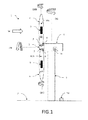
- Fig. 1 shows an embodiment of a wind turbine 1 according to the invention with pitch control consisting of several components comprising a tower 3, which carries the other components of the wind turbine and is anchored in the ground 2.
- a tower 3 which carries the other components of the wind turbine and is anchored in the ground 2.
- a gondola 4 rotatably mounted on the tower 3 about a rotation axis DG
- a rotor 5 with a hub 5 rotatably mounted on the nacelle 4 about a rotation axis DN and at least two rotor blades 6 supported in the hub 5
- the wind turbine 1 may comprise two rotor blades 6 or three rotor blades 6, wherein in the latter case the third rotor blade 6 is covered by the hub 5.
- the rotor blades 6 have in the wind W depending on the angle of attack to wind W buoyancy for rotating the rotor about the axis of rotation DN, each rotor blade 6 about its longitudinal axis (rotational axis DRB) is rotatably mounted in the hub 5, so that the angle of attack of each rotor blade 6 relative can be set to the wind W each by means of a pitch motor 7.
- Each of the rotor blades 6 here has a pitch motor 7, wherein the pitch motors 7 are arranged in the hub 5 and are provided from one or more also arranged in the hub 5 energy storage 8 with electrical energy.
- the pitch motors 7 and energy storage 8 rotate with the hub 5 in wind operation. Suitable energy stores are, for example, batteries or ultra-capacitors.
- all the energy storage devices 8 can be charged in parallel by the photovoltaic cells.
- only one energy storage 8 for the operation of a pitch motor 7 can be charged by the photovoltaic cells 9.
- the charging AR of the energy storage 8 for the pitch motors 7 in idle mode with several energy storage devices 8 can take place successively for each energy storage device 8, until at the end all energy storage devices are charged.
- the photovoltaic cells 9 are connected by means of electrical cable within the rotor blades 6 with the energy storage 8 directly or indirectly via the pitch motors 7.
- the advantage here is the easy-to-design electrical connection of the photovoltaic cells 9 with the energy storage 8, since all components do not move relative to each other.
- the rotation of the rotor blades 6 along the axis of rotation DRB is no obstacle, since the cable connections can be designed so flexible that rotations of the rotor blades by +/- 180 degrees or more without modification of the cable connections are easily tolerated.
- the photovoltaic cells 9 are arranged in this embodiment on at least one outer side 61 of each of the rotor blades 6, wherein the rotor blades 6 include a leading edge and an edge adjacent wing portion 61 for generating the lift, which is particularly well suited for the attachment of one or more photovoltaic cells 9 in this wing area 61 is suitable.
- the wing region 61 has a first surface 61a and a second surface 61b opposite the first surface 61a, the one or more photovoltaic cells 9 in the first surface 61a (upper rotor blade) and in the second surface 61b (lower rotor blade ) are arranged.
- the wind turbine 1 further comprises a controller 10 for the rotor blades 6, which is designed so that the rotor blades 6 equipped with one or more photovoltaic cells 9 are brought into a position PB of the wind turbine 1 in the idle mode, which is responsible for generating electrical energy the photovoltaic cells 9 is particularly favorable, so at least for one of the rotor blades 6 at an angle with the highest possible solar radiation. Since the geographical position of the wind turbine and the local position of the sun are known as a function of the time, the control can be done according to a correspondingly stored in the control cam as a function of time.
- Fig.2 shows an alternative embodiment of a wind turbine 1 according to the invention, in which the photovoltaic cells 9 are arranged here instead of the rotor blades 6 here on the nacelle 4.
- An arrangement of the photovoltaic cells 9 on the nacelle 4 facilitates their maintenance, since the nacelle 4 is more accessible than, for example, the wing surfaces 61 of the rotor blades 6. Since the nacelle but not co-rotated with the energy storage 8, an additional slip ring for the electrical connection between photovoltaic cells 9 and energy storage 8 necessary if a permanent electrical connection to the photovoltaic cells is desired.
- FIG. 1 refer to the description FIG. 1 directed.
- the photovoltaic cells 9 are arranged here, for example, on both lateral outer sides 4a of the nacelle 4 (rear side of the nacelle 4 is not visible), so that the photovoltaic cells are arranged on two outer sides 4a of the nacelle 4 facing in different directions, one of which faces the outside of the sun , Alternatively, the photovoltaic cells 9 can also be arranged on the upper outer side 4b of the nacelle, which always receives solar radiation regardless of the position of the sun, but only at lunchtime from a particularly favorable angle (preferably vertical incidence of solar radiation on the surface of the photovoltaic cells).
- the wind energy installation 1 comprises a controller 10 for the rotatable nacelle 4, which is designed such that the rotatable nacelle 4 equipped with one or more photovoltaic cells 9 is brought to a position PB in idle operation of the wind energy installation 1, which is responsible for generation of electrical energy through the photovoltaic cells 9 is particularly favorable.
- the controller 10 is additionally designed so that the rotor blades 6 are stopped in idle mode in a position in which the shading of the photovoltaic cells 9 to the nacelle 4 by the rotor blades 6 is minimal. Since the geographical position of the wind turbine 1 is known and the local position of the sun is a function of the time, the controller can after a correspondingly stored in the control cam as a function of time, also for the position of the rotor blades done.
- FIG. 3 shows a further alternative embodiment of a wind turbine 1 according to the invention with photovoltaic cells 9 on the hub 5.
- the photovoltaic cells 5 arranged on the outside of the hub 5 pointing away from the nacelle 4 are arranged asymmetrically about the pivot point 51 of the hub 5.
- the hub as seen from the side views of the FIGS. 1 and 2 is visible, usually has a curved shape, the surface of the photovoltaic cells 9 in the direction of solar radiation (upward), provided that the hub 5 in the in FIG. 3 position comes to a halt.
- the photovoltaic cells 9 are arranged only in the upper, the solar radiation facing half of the hub 5 and therefore in a particularly favorable position for generating solar power.
- This position can be adjusted by a controller 10 for the hub 5, which is designed so that the equipped with one or more photovoltaic cell / n 9 hub 5 is brought in idle operation of the wind turbine 1 in this favorable position for the solar power generation PB.
- the photovoltaic cells 9 disposed on the outside of the hub 5 facing away from the nacelle 4 may be arranged symmetrically about the fulcrum of the hub 5, thus obviating control for proper positioning of the hub.
- a controller 10 for the alignment of the hub 5 to the sun by rotation of the nacelle 4 is provided about the axis of rotation DG.
- the controller 10 can be arranged in at least one of the rotatable components 4, 5, 6 or in the tower 3 or on the ground 2.
- the controller is suitably connected to the motors for rotating the rotatable components 4, 5, 6.
- Figure 4 1 shows a section of a rotor blade 6, which comprises a plurality of photovoltaic cells 9, which are arranged in recesses 62 in the wing region 61, wherein the recesses 62 suitably adapted to the shape of the photovoltaic cells 9 are.
- the photovoltaic cells with a transparent cover 91 (shown in gray) above the photovoltaic cells 9 (shown in phantom, as disposed below the cover) as part of the surface 61 a, 61 b of the wing portion 61 covered.
- the cover 62 must be at least largely transparent at least in the spectral range of the solar spectrum, the radiation of which is used for solar power generation by converting the solar energy into electrical energy.
- Suitable covers are known in the art.
- the own surfaces of the photovoltaic cells 9, the surface 61 a, 61 b of the wing portion 61, so that a cover, as in 4 (a) shown can be avoided.
- small-area photovoltaic cells 9 are particularly expedient in this exemplary embodiment, which are assembled to a corresponding total area with the required size for the generation of solar power.
- the examples shown also apply to an arrangement of the photovoltaic cells on the hub 5 or the nacelle 4.
- the surfaces 61 a shown would be the outer surface of the hub 5 or the nacelle 4.
- photovoltaic cells can also be mounted on the surfaces of the rotatable components 4, 5, 6, for example, the photovoltaic cells 9 can be glued to the respective surfaces.
- the photovoltaic cells 9 can be glued to the respective surfaces.
- only one hole would have to be provided for the passage of the electrical cables from the photovoltaic cells 9 into the interior of the rotatable components 4, 5, 6.
- This has the advantage that the total area of the photovoltaic cells can be arbitrarily varied within the available surfaces according to the power requirements for the pitch motors 7 and optionally for the power supply of other components and the power generation efficiency (position of the wind turbine, degree of solar radiation) without additional adaptation effort.
- Flexible photovoltaic cells are particularly suitable for bonded-on photovoltaic cells, since they also conform to curved surfaces, for example photovoltaic cells made of organic material.
- the advantage of photovoltaic cells arranged in corresponding recesses is that the Flow properties, for example, the rotor blades 6 and the hub 5 are not affected by the existing photovoltaic cells 9.
- a transparent cover 62 additionally protects the photovoltaic cells against external mechanical influences, for example hail or bird strike.
- photovoltaic cells whose surface simultaneously represents the surface of the rotors 6 or hub 5 (eg flexible photovoltaic cells), simplify the assembly of the photovoltaic cells.
- the size of the total area, which must be covered by photovoltaic cells 9 so that the necessary energy can be provided for charging the energy storage 8, results from the technical data of the respective wind turbine 1 and from the data for the solar radiation at the geographical location of the wind turbine 1. In Germany, for example, there is an average solar radiation of 650 - 1150 kWh per kW-peak and year. A typical photovoltaic system generates 1 kW peak for a total area of 10 m 2 . This results in an energy yield of 65 - 115 kWh per square meter photovoltaic cell area and year for Germany.
- High wind rotors have, for example, wing areas of up to or more than 1000 m 2 .
- Pitch motors 7 of a 6 MW wind turbines have, for example, a power of 7.5 kW per pitch motor 7, the pitch motor 7, for example, from a series connection of eighteen 12 V battery as energy storage 8, each with a capacity of 7.2 Ah or 12.0 Ah is fed.
- the self-discharge of such batteries is about 9% after 3 months.
- a photovoltaic system would therefore have to generate 78 Wh per month to compensate for the self-discharge of eighteen batteries, for which a total area of 16 cm 2 per battery to be supplied (including a 100% safety reserve) would be sufficient. With a total of eighteen batteries to be charged, the total area including a corresponding safety margin is then 300 cm 2 .
- the area should be equipped with photovoltaic cells correspondingly larger.
- photovoltaic cells correspondingly larger.
- ultra-capacitors the faster Show self-discharge as batteries, a minimum area of 25 cm 2 per supplied ultra-capacitor energy storage 8 would be sufficient, the total area then scaled with the number of ultra-capacitors used. If additional components of the wind turbine 1 are to be additionally supplied with electrical energy by the photovoltaic cells 9, the required total area would have to be correspondingly larger by the person skilled in the art.
- the photovoltaic cells 9 depending on the arrangement of the respective rotatable component and their level for solar radiation do not provide the average energy yield typical for Germany, but less. If, in addition, a safety margin is added to compensate for below-average energy yields, then total areas for photovoltaic cells 9 even below 1 m 2 would be usable for charging the energy stores for the pitch motors. In addition, unfavorable climatic conditions during operation of the wind turbine 1 can cause a faster self-discharge of the energy storage, which also leads to a larger surface to be dimensioned of the photovoltaic cells. Similarly, the deviations of the average solar radiation from the values typical for Germany when operating the wind energy plants at another geographical location must be taken into account.
- FIG. 5 shows an embodiment of a method according to the invention for charging the energy storage 8 of the pitch motors 7 of a wind turbine 1 according to the invention.
- the method comprises the steps of charging AW all energy storage 8 (dashed arrow) for the pitch motors 7 during wind operation (suitable wind available: "J") the wind turbine 1 by means of the energy generated by the wind turbine 1 WE.
- the energy storage devices can also be charged by a connected power grid and / or by means of the solar power generated by the photovoltaic cells 9 during wind operation.
- the energy storage device (s) charged in this way are, at a desired end of the quiescent operation, able to supply the pitch motors with the necessary energy for rotating the rotor blades 6, so that an angle of attack suitable for the wind operation for at least one of the rotor blades 6 by the pitch motors 7 can be adjusted.
- the energy storage devices 8 can be charged again from wind energy WE.
- the method preferably comprises the additional step that the controller 10 of the wind energy installation 1 for the rotatable components 4, 5, 6 brings the rotatable components 4, 5, 6 equipped with one or more photovoltaic cells 9 into a position PB in the idle mode of the wind power installation 1, which is particularly favorable for a generation of electrical energy by the photovoltaic cells 9.
Landscapes
- Engineering & Computer Science (AREA)
- Life Sciences & Earth Sciences (AREA)
- Sustainable Development (AREA)
- Sustainable Energy (AREA)
- Chemical & Material Sciences (AREA)
- Combustion & Propulsion (AREA)
- Mechanical Engineering (AREA)
- General Engineering & Computer Science (AREA)
- Power Engineering (AREA)
- Physics & Mathematics (AREA)
- Fluid Mechanics (AREA)
- Wind Motors (AREA)
Priority Applications (1)
| Application Number | Priority Date | Filing Date | Title |
|---|---|---|---|
| EP12165971.8A EP2657515A1 (fr) | 2012-04-27 | 2012-04-27 | Éolienne avec régulation du pas |
Applications Claiming Priority (1)
| Application Number | Priority Date | Filing Date | Title |
|---|---|---|---|
| EP12165971.8A EP2657515A1 (fr) | 2012-04-27 | 2012-04-27 | Éolienne avec régulation du pas |
Publications (1)
| Publication Number | Publication Date |
|---|---|
| EP2657515A1 true EP2657515A1 (fr) | 2013-10-30 |
Family
ID=46052578
Family Applications (1)
| Application Number | Title | Priority Date | Filing Date |
|---|---|---|---|
| EP12165971.8A Withdrawn EP2657515A1 (fr) | 2012-04-27 | 2012-04-27 | Éolienne avec régulation du pas |
Country Status (1)
| Country | Link |
|---|---|
| EP (1) | EP2657515A1 (fr) |
Cited By (6)
| Publication number | Priority date | Publication date | Assignee | Title |
|---|---|---|---|---|
| WO2017190747A1 (fr) * | 2016-05-04 | 2017-11-09 | Vestas Wind Systems A/S | Génération et stockage d'énergie dans le moyeu pour antigivrage de pales d'éolienne |
| CN107905947A (zh) * | 2017-11-02 | 2018-04-13 | 江苏燕山光伏设备有限公司 | 一种太阳能风力综合式发电装置 |
| CN110107451A (zh) * | 2019-05-17 | 2019-08-09 | 杭州虹妍服饰有限公司 | 一种风力涡轮机 |
| CN111120220A (zh) * | 2018-10-31 | 2020-05-08 | 北京金风科创风电设备有限公司 | 风力发电机组叶片视频监测的方法及系统 |
| CN111509568A (zh) * | 2020-04-30 | 2020-08-07 | 山东商务职业学院 | 一种机电一体化配电柜保护装置 |
| US11936328B2 (en) | 2018-08-21 | 2024-03-19 | Vestas Wind Systems A/S | Method of operating a hybrid power plant to optimize PV power output |
Citations (9)
| Publication number | Priority date | Publication date | Assignee | Title |
|---|---|---|---|---|
| GB2187512A (en) * | 1985-11-08 | 1987-09-09 | Cecil Arthur Johnson | Combined solar power and wind power generator |
| US5254876A (en) * | 1992-05-28 | 1993-10-19 | Hickey John J | Combined solar and wind powered generator with spiral blades |
| DE202004007992U1 (de) * | 2004-05-18 | 2004-09-16 | Tönges, Gerd Otto | Kombinierte Wind- und Sonnenenergie-Kraftwerke zur Erzeugung von elektrischem Strom |
| EP1961957A2 (fr) | 2005-07-22 | 2008-08-27 | Gamesa Innovation & Technology, S.L. | Procede permettant de maintenir en fonctionnement les composants d'une turbine eolienne et turbine equipee de composants permettant le maintien en fonctionnement |
| EP2108825A2 (fr) * | 2008-04-01 | 2009-10-14 | General Electric Company | Système et procédé de réduction des charges de rotor dans une éolienne après détection d'un échec de pas de pale et perte de couple de réaction |
| EP2146095A2 (fr) | 2008-07-16 | 2010-01-20 | General Electric Company | Utilisation d'alimentation de batterie à pas pour démarrer une éolienne durant la perte de réseau/capacité de démarrage à froid |
| US20100320760A1 (en) * | 2009-06-22 | 2010-12-23 | POWER LIGHT Tech. Co., Ltd. | Solar and Wind Power Generator Capable of Tracking Sunlight Automatically |
| US20110031761A1 (en) * | 2008-01-25 | 2011-02-10 | Deangeles Steven J | Momentum-Conserving Wind-Driven Electrical Generator |
| US20110121575A1 (en) * | 2009-11-25 | 2011-05-26 | Gary Anetrini | Systems, methods, and kits for power generation |
-
2012
- 2012-04-27 EP EP12165971.8A patent/EP2657515A1/fr not_active Withdrawn
Patent Citations (9)
| Publication number | Priority date | Publication date | Assignee | Title |
|---|---|---|---|---|
| GB2187512A (en) * | 1985-11-08 | 1987-09-09 | Cecil Arthur Johnson | Combined solar power and wind power generator |
| US5254876A (en) * | 1992-05-28 | 1993-10-19 | Hickey John J | Combined solar and wind powered generator with spiral blades |
| DE202004007992U1 (de) * | 2004-05-18 | 2004-09-16 | Tönges, Gerd Otto | Kombinierte Wind- und Sonnenenergie-Kraftwerke zur Erzeugung von elektrischem Strom |
| EP1961957A2 (fr) | 2005-07-22 | 2008-08-27 | Gamesa Innovation & Technology, S.L. | Procede permettant de maintenir en fonctionnement les composants d'une turbine eolienne et turbine equipee de composants permettant le maintien en fonctionnement |
| US20110031761A1 (en) * | 2008-01-25 | 2011-02-10 | Deangeles Steven J | Momentum-Conserving Wind-Driven Electrical Generator |
| EP2108825A2 (fr) * | 2008-04-01 | 2009-10-14 | General Electric Company | Système et procédé de réduction des charges de rotor dans une éolienne après détection d'un échec de pas de pale et perte de couple de réaction |
| EP2146095A2 (fr) | 2008-07-16 | 2010-01-20 | General Electric Company | Utilisation d'alimentation de batterie à pas pour démarrer une éolienne durant la perte de réseau/capacité de démarrage à froid |
| US20100320760A1 (en) * | 2009-06-22 | 2010-12-23 | POWER LIGHT Tech. Co., Ltd. | Solar and Wind Power Generator Capable of Tracking Sunlight Automatically |
| US20110121575A1 (en) * | 2009-11-25 | 2011-05-26 | Gary Anetrini | Systems, methods, and kits for power generation |
Cited By (8)
| Publication number | Priority date | Publication date | Assignee | Title |
|---|---|---|---|---|
| WO2017190747A1 (fr) * | 2016-05-04 | 2017-11-09 | Vestas Wind Systems A/S | Génération et stockage d'énergie dans le moyeu pour antigivrage de pales d'éolienne |
| CN107905947A (zh) * | 2017-11-02 | 2018-04-13 | 江苏燕山光伏设备有限公司 | 一种太阳能风力综合式发电装置 |
| US11936328B2 (en) | 2018-08-21 | 2024-03-19 | Vestas Wind Systems A/S | Method of operating a hybrid power plant to optimize PV power output |
| CN111120220A (zh) * | 2018-10-31 | 2020-05-08 | 北京金风科创风电设备有限公司 | 风力发电机组叶片视频监测的方法及系统 |
| CN111120220B (zh) * | 2018-10-31 | 2021-05-28 | 北京金风科创风电设备有限公司 | 风力发电机组叶片视频监测的方法及系统 |
| CN110107451A (zh) * | 2019-05-17 | 2019-08-09 | 杭州虹妍服饰有限公司 | 一种风力涡轮机 |
| CN110107451B (zh) * | 2019-05-17 | 2020-12-25 | 广西电网有限责任公司河池供电局 | 一种风力涡轮机 |
| CN111509568A (zh) * | 2020-04-30 | 2020-08-07 | 山东商务职业学院 | 一种机电一体化配电柜保护装置 |
Similar Documents
| Publication | Publication Date | Title |
|---|---|---|
| EP2275676B1 (fr) | Parc d'éoliennes avec capacité de redémarrage à froid | |
| DE102005050251B3 (de) | Rotor-Segel und Schiff mit Rotor-Segel | |
| DE60010843T2 (de) | Windturbine mit gegenläufigen rotoren | |
| DE102008024829B4 (de) | Windkraftanlage | |
| EP2657515A1 (fr) | Éolienne avec régulation du pas | |
| WO2006015850A2 (fr) | Centrale electrique hybride | |
| EP1767781A2 (fr) | Méthode pour l'adaptation d'une éolienne aux conditions du vent | |
| EP3152437B1 (fr) | Éolienne et procédé pour faire fonctionner un tel équipement | |
| AT517774B1 (de) | Windenergieanlage und Windpark mit Windenergieanlage | |
| WO2000019094A1 (fr) | Logique de commande pour centrale eolienne | |
| EP2140136B1 (fr) | Éolienne | |
| DE102005062615A1 (de) | Windkraftanlage | |
| DE102011109217A1 (de) | Zwillingsturbinensystem, das dem Wind/Wasser folgt (Windtracker), für Wind und/oder Wasserkraft | |
| DE102011056980A1 (de) | Windkraftanlage | |
| EP3926162A1 (fr) | Procédé de fonctionnement d'une éolienne, dispositif de commande destiné au fonctionnement d'un éolienne et parc éolien | |
| DE202012009612U1 (de) | Elektrostatische Windenergieanlage mit Mini-Rotoren | |
| EP2522847B1 (fr) | Parque de centrales d'énergie hydraulique et son procédé de fabrication | |
| EP3221578B1 (fr) | Conception d'une éolienne | |
| DE102008047261A1 (de) | Vorrichtung zur Stromerzeugung mittels Zugdrachen | |
| WO2016139082A1 (fr) | Procédé pour faire fonctionner une éolienne | |
| DE102011101368A1 (de) | Strömungskraftwerk und Verfahren für dessen Betrieb | |
| DE102018113760A1 (de) | Rotorlagergehäuse und Windenergieanlage mit Rotorlagergehäuse | |
| DE102010006336A1 (de) | Windkraftanlage | |
| DE202015102425U1 (de) | Drehbare Plattform-Vorrichtung für Offshore-Windkraftanlagen | |
| DE202010002046U1 (de) | Computergesteuert Wind- Wasserturbine Matsak |
Legal Events
| Date | Code | Title | Description |
|---|---|---|---|
| PUAI | Public reference made under article 153(3) epc to a published international application that has entered the european phase |
Free format text: ORIGINAL CODE: 0009012 |
|
| AK | Designated contracting states |
Kind code of ref document: A1 Designated state(s): AL AT BE BG CH CY CZ DE DK EE ES FI FR GB GR HR HU IE IS IT LI LT LU LV MC MK MT NL NO PL PT RO RS SE SI SK SM TR |
|
| AX | Request for extension of the european patent |
Extension state: BA ME |
|
| 17P | Request for examination filed |
Effective date: 20140428 |
|
| RBV | Designated contracting states (corrected) |
Designated state(s): AL AT BE BG CH CY CZ DE DK EE ES FI FR GB GR HR HU IE IS IT LI LT LU LV MC MK MT NL NO PL PT RO RS SE SI SK SM TR |
|
| 17Q | First examination report despatched |
Effective date: 20161124 |
|
| RIN1 | Information on inventor provided before grant (corrected) |
Inventor name: THEOPOLD, TOBIAS Inventor name: LEHMANN, FELIX JOHAN |
|
| STAA | Information on the status of an ep patent application or granted ep patent |
Free format text: STATUS: THE APPLICATION IS DEEMED TO BE WITHDRAWN |
|
| 18D | Application deemed to be withdrawn |
Effective date: 20170607 |