EP2657515A1 - Wind energy assembly with pitch regulation - Google Patents
Wind energy assembly with pitch regulation Download PDFInfo
- Publication number
- EP2657515A1 EP2657515A1 EP12165971.8A EP12165971A EP2657515A1 EP 2657515 A1 EP2657515 A1 EP 2657515A1 EP 12165971 A EP12165971 A EP 12165971A EP 2657515 A1 EP2657515 A1 EP 2657515A1
- Authority
- EP
- European Patent Office
- Prior art keywords
- photovoltaic cells
- wind
- energy
- hub
- rotor
- Prior art date
- Legal status (The legal status is an assumption and is not a legal conclusion. Google has not performed a legal analysis and makes no representation as to the accuracy of the status listed.)
- Withdrawn
Links
- 238000004146 energy storage Methods 0.000 claims abstract description 64
- 238000000034 method Methods 0.000 claims abstract description 13
- 230000002349 favourable effect Effects 0.000 claims description 23
- 238000009434 installation Methods 0.000 claims description 13
- 230000001419 dependent effect Effects 0.000 claims 1
- 230000000284 resting effect Effects 0.000 claims 1
- 230000005855 radiation Effects 0.000 description 14
- 238000010248 power generation Methods 0.000 description 8
- 238000012423 maintenance Methods 0.000 description 7
- 239000003990 capacitor Substances 0.000 description 5
- 230000008901 benefit Effects 0.000 description 3
- 238000003860 storage Methods 0.000 description 3
- 238000001228 spectrum Methods 0.000 description 2
- 229920000049 Carbon (fiber) Polymers 0.000 description 1
- 230000006978 adaptation Effects 0.000 description 1
- 230000005540 biological transmission Effects 0.000 description 1
- 230000015572 biosynthetic process Effects 0.000 description 1
- 239000004917 carbon fiber Substances 0.000 description 1
- 230000008859 change Effects 0.000 description 1
- 230000000694 effects Effects 0.000 description 1
- 239000011152 fibreglass Substances 0.000 description 1
- 230000005923 long-lasting effect Effects 0.000 description 1
- 238000004519 manufacturing process Methods 0.000 description 1
- 239000000463 material Substances 0.000 description 1
- 230000004048 modification Effects 0.000 description 1
- 238000012986 modification Methods 0.000 description 1
- 239000011368 organic material Substances 0.000 description 1
- 230000002035 prolonged effect Effects 0.000 description 1
- 230000004044 response Effects 0.000 description 1
- 238000004513 sizing Methods 0.000 description 1
- 239000002689 soil Substances 0.000 description 1
- 230000003595 spectral effect Effects 0.000 description 1
- 230000007704 transition Effects 0.000 description 1
Images


Classifications
-
- F—MECHANICAL ENGINEERING; LIGHTING; HEATING; WEAPONS; BLASTING
- F03—MACHINES OR ENGINES FOR LIQUIDS; WIND, SPRING, OR WEIGHT MOTORS; PRODUCING MECHANICAL POWER OR A REACTIVE PROPULSIVE THRUST, NOT OTHERWISE PROVIDED FOR
- F03D—WIND MOTORS
- F03D7/00—Controlling wind motors
- F03D7/02—Controlling wind motors the wind motors having rotation axis substantially parallel to the air flow entering the rotor
- F03D7/022—Adjusting aerodynamic properties of the blades
- F03D7/0224—Adjusting blade pitch
-
- F—MECHANICAL ENGINEERING; LIGHTING; HEATING; WEAPONS; BLASTING
- F03—MACHINES OR ENGINES FOR LIQUIDS; WIND, SPRING, OR WEIGHT MOTORS; PRODUCING MECHANICAL POWER OR A REACTIVE PROPULSIVE THRUST, NOT OTHERWISE PROVIDED FOR
- F03D—WIND MOTORS
- F03D9/00—Adaptations of wind motors for special use; Combinations of wind motors with apparatus driven thereby; Wind motors specially adapted for installation in particular locations
- F03D9/20—Wind motors characterised by the driven apparatus
- F03D9/25—Wind motors characterised by the driven apparatus the apparatus being an electrical generator
-
- F—MECHANICAL ENGINEERING; LIGHTING; HEATING; WEAPONS; BLASTING
- F03—MACHINES OR ENGINES FOR LIQUIDS; WIND, SPRING, OR WEIGHT MOTORS; PRODUCING MECHANICAL POWER OR A REACTIVE PROPULSIVE THRUST, NOT OTHERWISE PROVIDED FOR
- F03D—WIND MOTORS
- F03D7/00—Controlling wind motors
- F03D7/02—Controlling wind motors the wind motors having rotation axis substantially parallel to the air flow entering the rotor
- F03D7/0264—Controlling wind motors the wind motors having rotation axis substantially parallel to the air flow entering the rotor for stopping; controlling in emergency situations
- F03D7/0268—Parking or storm protection
-
- H—ELECTRICITY
- H02—GENERATION; CONVERSION OR DISTRIBUTION OF ELECTRIC POWER
- H02S—GENERATION OF ELECTRIC POWER BY CONVERSION OF INFRARED RADIATION, VISIBLE LIGHT OR ULTRAVIOLET LIGHT, e.g. USING PHOTOVOLTAIC [PV] MODULES
- H02S10/00—PV power plants; Combinations of PV energy systems with other systems for the generation of electric power
- H02S10/10—PV power plants; Combinations of PV energy systems with other systems for the generation of electric power including a supplementary source of electric power, e.g. hybrid diesel-PV energy systems
- H02S10/12—Hybrid wind-PV energy systems
-
- F—MECHANICAL ENGINEERING; LIGHTING; HEATING; WEAPONS; BLASTING
- F05—INDEXING SCHEMES RELATING TO ENGINES OR PUMPS IN VARIOUS SUBCLASSES OF CLASSES F01-F04
- F05B—INDEXING SCHEME RELATING TO WIND, SPRING, WEIGHT, INERTIA OR LIKE MOTORS, TO MACHINES OR ENGINES FOR LIQUIDS COVERED BY SUBCLASSES F03B, F03D AND F03G
- F05B2260/00—Function
- F05B2260/70—Adjusting of angle of incidence or attack of rotating blades
- F05B2260/76—Adjusting of angle of incidence or attack of rotating blades the adjusting mechanism using auxiliary power sources
-
- F—MECHANICAL ENGINEERING; LIGHTING; HEATING; WEAPONS; BLASTING
- F05—INDEXING SCHEMES RELATING TO ENGINES OR PUMPS IN VARIOUS SUBCLASSES OF CLASSES F01-F04
- F05B—INDEXING SCHEME RELATING TO WIND, SPRING, WEIGHT, INERTIA OR LIKE MOTORS, TO MACHINES OR ENGINES FOR LIQUIDS COVERED BY SUBCLASSES F03B, F03D AND F03G
- F05B2260/00—Function
- F05B2260/85—Starting
-
- Y—GENERAL TAGGING OF NEW TECHNOLOGICAL DEVELOPMENTS; GENERAL TAGGING OF CROSS-SECTIONAL TECHNOLOGIES SPANNING OVER SEVERAL SECTIONS OF THE IPC; TECHNICAL SUBJECTS COVERED BY FORMER USPC CROSS-REFERENCE ART COLLECTIONS [XRACs] AND DIGESTS
- Y02—TECHNOLOGIES OR APPLICATIONS FOR MITIGATION OR ADAPTATION AGAINST CLIMATE CHANGE
- Y02E—REDUCTION OF GREENHOUSE GAS [GHG] EMISSIONS, RELATED TO ENERGY GENERATION, TRANSMISSION OR DISTRIBUTION
- Y02E10/00—Energy generation through renewable energy sources
- Y02E10/50—Photovoltaic [PV] energy
-
- Y—GENERAL TAGGING OF NEW TECHNOLOGICAL DEVELOPMENTS; GENERAL TAGGING OF CROSS-SECTIONAL TECHNOLOGIES SPANNING OVER SEVERAL SECTIONS OF THE IPC; TECHNICAL SUBJECTS COVERED BY FORMER USPC CROSS-REFERENCE ART COLLECTIONS [XRACs] AND DIGESTS
- Y02—TECHNOLOGIES OR APPLICATIONS FOR MITIGATION OR ADAPTATION AGAINST CLIMATE CHANGE
- Y02E—REDUCTION OF GREENHOUSE GAS [GHG] EMISSIONS, RELATED TO ENERGY GENERATION, TRANSMISSION OR DISTRIBUTION
- Y02E10/00—Energy generation through renewable energy sources
- Y02E10/70—Wind energy
- Y02E10/72—Wind turbines with rotation axis in wind direction
Definitions
- the invention relates to a wind energy plant with pitch control, which is equipped with one or more photovoltaic cells for powering the pitch motors, to a rotatable component of the wind turbine, which is equipped with one or more photovoltaic cells for powering the pitch motors, and to a method for operating a such a wind turbine.
- Wind turbines use their rotors to convert wind energy into electrical energy for feeding into a power grid.
- the rotors have for this purpose at least one rotor blade, with most wind turbines having a rotor with three rotor blades.
- a wind turbine essentially consists of a rotor with hub and rotor blades and a nacelle, which houses the generator and often a gearbox.
- the nacelle is rotatably mounted on a tower whose foundation gives the necessary stability. Depending on the wind direction, the nacelle is turned into the wind so that a corresponding amount of wind energy can be converted via the rotation of the rotor in the generator into electrical energy.
- the wind turbines are approached by a control electronics at wind speeds promising higher than a start-up speed and turned off at excessive wind speeds greater than a shutdown speed again.
- the wind speed can be determined by the controller via an anemometer or derived from the speed of the rotor and the output power.
- a shutdown of the wind turbines can also be caused by a lack of grid connection or by a network failure.
- So-called pitch-controlled wind turbines represent the state of the art today. Turning the rotor blades into and out of the wind is called "pitching". So that the rotor blades can be turned, these are in rotatably mounted on the hub and are rotated by a pitch motor in the desired position.
- the rotor blades have depending on the angle of attack to the wind greater or lesser buoyancy, which sets the rotor in rotation. Pitch control also allows the rotor to be stopped by turning the rotor blades to a position that decelerates the rotor to a standstill, even in windy conditions. If the rotor is to remain at a standstill, the angle of attack of the rotor blades is selected so that the rotor blades do not experience buoyancy by the wind. As long as the wind turbine generates electrical energy, it can independently supply the pitch motors with energy. However, it is problematic when the wind turbine is taken off the grid. In this case, the angle of attack of the rotor blades is adjusted so that the wind turbine generates no electrical energy.
- a wind turbine with pitch control of several components comprising a tower, a rotatably mounted on the tower nacelle, rotatably mounted on the nacelle rotor with hub and at least one held in the hub rotor blade, in the wind one of the angle of attack to the wind each rotor blade is mounted rotatably about its longitudinal axis in the hub and the angle of attack of each rotor blade relative to the wind can each be adjusted by means of a arranged in the hub or in the rotor blade pitch motor, the pitch motor of one or more Energy storage can be provided with electrical energy and at least one of the rotatable components is equipped with one or more photovoltaic cells, which are connected to at least one of the energy storage, that one or more Photovoltaic cells can supply at least the energy storage for the pitch motor with electrical energy.
- a wind turbine converts the energy of the wind into electrical energy and usually feeds it into a connected power grid.
- Wind turbines can be arranged on land or as so-called offshore installations in the area of moderate depths off the coast. Onshore wind turbines typically deliver up to 3MW of electrical energy, while so-called offshore installations can deliver up to 6MW of electrical energy since they may be larger or more powerful due to the lower restrictions on land height, rotor size, and higher wind supply. For the maintenance of offshore installations is higher because of their difficult accessibility. Especially for such wind turbines, operation with the least possible maintenance is important.
- Wind turbines may comprise a single rotor blade or a plurality of rotor blades, for example two, three or four rotor blades. Typically, wind turbines include three rotor blades, since here the storage of the hub and the rotor is most favorable.
- a wind energy plant comprises a tower for holding the rotatable components.
- the minimum height of the tower is determined inter alia by the rotor diameter.
- the rotor diameter is the diameter of the surface within which the rotor blades rotate in the wind.
- Wind turbines can have very different rotor diameters up to more than 120m. Due to the local wind currents, land-based turbines with higher towers also provide higher energy than land-based systems with smaller towers.
- On the tower a nacelle is rotatably mounted, wherein the axis of rotation of the nacelle (nacelle axis of rotation) is usually perpendicular to the earth's surface.
- the rotor is mounted with hub and rotor blades and connected to a generator for power generation.
- the nacelle is therefore also referred to as a nacelle.
- the nacelle may additionally comprise a transmission.
- the wind direction tracking takes place recordable by servo motors, the wind direction is determined by so-called Wind traditionsssensoren.
- the electrical connection of the nacelle to the power grid is usually via permanently connected to the nacelle cables.
- the hub refers to the part of the rotor which is rotatably arranged at the same height in front of the nacelle and in which the rotor blades are mounted.
- the axis of rotation of the rotor and thus also the hub and the blades attached to it in wind operation is substantially perpendicular to the nacelle axis of rotation.
- one or more rotor blades are supported for the rotation of the rotor for generating electrical energy from the wind energy.
- the rotor blade is shaped such that the wind impinging on the rotor blade generates a lift for the rotor blade, so that the rotor is set in rotation as a result of the buoyancy of the rotor blades.
- Modern rotor blades have a wing-like shape and are usually made of glass fiber reinforced plastic or carbon fibers.
- rotor blades may have a rotor blade heater. Such a rotor blade heater may, for example, have a power of a few kW.
- the strength of the buoyancy for the rotor blades depends on their angle of attack to the wind.
- the angle of attack here denotes the angle between the wind direction and the surface of the wing-shaped part of the rotor blades.
- the rotor blade is mounted rotatably about its longitudinal axis in the hub.
- the adjustable angle of attack can also be used for stopping (braking) and starting (starting to rotate) the rotor. At wind speeds suitable for power generation, the previously stationary rotor is approached; if the wind speeds are too high, the wind turbine is switched off to protect the system and the rotor is stopped.
- the wind speed can be determined via an anemometer and with a corresponding control a rotation ("pitching") of the rotor blades are made according to the determined wind speed.
- the rotation of the rotor blades via a so-called pitch motor, which is arranged within the hub.
- the deceleration of the system can be achieved or supported for example via a corresponding, the rotation of the rotor blades braking angle. If the wind speed is too low for economical operation of the plant or if the rotor is not intended to rotate in idle operation (or standstill operation) of the wind turbine, the angle of attack is brought to a zero-degree position to the wind (feathering).
- a wind energy plant may comprise further rotatable components.
- the pitch motors In order for the pitch motors to be supplied with the necessary electrical energy, they are connected to one or more energy stores as an energy source.
- energy storage can be, for example, batteries or super-capacitors. So that the electrical connection to the pitch motors simplified and an electrical slip ring for contacting non-rotating components can be avoided, both the pitch motors and the energy storage are mounted on or in the hub or on the rotor, so that both the pitch motors and the energy storage rotate during operation of the wind turbine with the hub. In contrast to nonmitrot Schlierenden energy storage, a slip ring for electrical contacting of the pitch motors can be avoided.
- the pitch motors can be fed during wind operation (generation of electrical energy from wind energy), for example, from a part of the generated electrical energy.
- this energy source is not available when the wind turbine is at a standstill, for example due to a lack of wind or a shutdown of the wind energy due to excessive wind or due to a power failure. Should such a standstill operation (idle operation) continue for a longer time, the energy storage devices for operating the pitch motors would be so heavily discharged due to their self-discharge without further measures that the rotor blades are no longer moved by the pitch motors into one position can be rotated with suitable buoyancy for starting the wind turbine.
- the wind power installation according to the invention comprises one or more photovoltaic cells which supply at least one or more of the energy stores for the pitch motor (s) with electrical energy.
- the number and arrangement of the photovoltaic cells is chosen so that at least the self-discharge of the energy storage for the pitch motors can be compensated.
- photovoltaic cell refers to an arrangement or installation in which the solar radiation is converted into electrical energy.
- a photovoltaic cell is also called a solar cell.
- Photovoltaic cells have a long life span of more than 20 years and are available as thin modules on the market so that they can be easily attached to surfaces or integrated into surfaces.
- the desired amount of electrical energy generated by the photovoltaic cells can be provided by a correspondingly large selected area equipped with photovoltaic cells.
- Photovoltaic cells are characterized in that they can be modularly connected to a common photovoltaic module / system of one or more photovoltaic cells with a basically arbitrary selectable surface.
- the amount of solar power which the photovoltaic cells can supply in total depends not only on the common area of the photovoltaic cells, but also on their orientation to the sun and the weather-related insolation. The person skilled in the art is able to adapt the size of the common area of the photovoltaic cells to the demand for electrical energy from solar energy.
- a particularly favorable orientation of the photovoltaic cells to the sun denotes an angle between the solar irradiation direction and the surface of the photovoltaic cells, which is as close as possible to 90 degrees. This angle should not be less than 30 degrees for effective generation of solar energy.
- the photovoltaic cells are arranged on at least one outer side of the rotor blade or in the case of a plurality of rotor blades on at least one outer side of one of the rotor blades and / or on an outer side of the hub pointing away from the nacelle.
- the photovoltaic cells are arranged on at least one outer side of each of the rotor blades.
- the arrangement can also take place on both sides of each rotor blade.
- the outside here refers to the side of the rotor blade, which can be illuminated by the sun at least in a suitable position of the rotor blade.
- the rotor blade comprises a front edge and a wing region adjoining the edge for generating the buoyancy, wherein the one or more photovoltaic cells are arranged in the wing region.
- the arrangement of the photovoltaic cell / s on at least one outer side of the rotor blades or is advantageous because they have a large area, especially in the wing area and thus have sufficient space for the arrangement of photovoltaic cells with a suitable minimum total area.
- at least the outer surface of one of the rotor blades is in an especially favorable for the solar power generation by the photovoltaic cells angle to the sun or sunlight.
- the outer side of the rotor blades or the hub comprises one or more recesses / s adapted to the size and shape of the photovoltaic cells, in which the one or more photovoltaic cells are arranged.
- the photovoltaic cells are not mounted on the surface, but integrated into the surface.
- the shape of the outside of the rotor blades is not changed, so that the rotor blades continue to retain the original shape and thus the original properties for the generation of a buoyant force by the wind.
- the recesses can be clad, for example, above the photovoltaic cells (facing outward) with a material that is at least largely transparent to the solar radiation in the spectrum that can be used by the photovoltaic cells, so that the outer shape of the rotor blade to maintain its Ströumgseigenschaften corresponds to the shape of the rotor blade without the photovoltaic cells would have.
- the surface (s) of the one or more photovoltaic cells in the area of the recess represents the surface of the rotor blade or the hub.
- the wing region has a first surface and a second surface opposite the first surface, wherein the one or more photovoltaic cells are disposed in the first and second surfaces.
- one of the surfaces always faces the sun, so that it requires a particularly suitable orientation of the rotor blade to the sun at most at low solar radiation.
- a rotor with three rotor blades all rotor blades on both (first and second) surfaces equipped with photovoltaic cells can be dispensed with a special orientation of the rotor blades to the sun, as in any position of the rotor always a surface has a favorable position to the sun.
- shading effects by another shadow-throwing rotor blade do not negatively affect the power generation by the photovoltaic cells, since always a surface of the sun is particularly favorable and thus can not be shaded by the other rotor blades.
- the photovoltaic cells arranged on the outside of the hub pointing away from the nacelle are arranged symmetrically about the pivot point of the hub. This ensures that even without setting a particularly favorable position of the hub, the shape of which is generally conical in the rule, always at least a portion of the arranged on the hub photovoltaic cells are particularly favorable to the sun.
- the photovoltaic cells are arranged on at least one outer side, preferably on at least two outer sides pointing in different directions, of the nacelle and electrically connected to the energy stores for the pitch motors or to the pitch motors at least in idle mode (non-rotating rotor).
- This electrical connection can be interrupted in wind operation, since the energy storage can then be supplied via the electrical energy obtained from the wind power.
- a permanent electrical connection between photovoltaic cells and energy storage can be achieved for example via a slip ring.
- the nacelle has a curved outside at least in the vicinity of the hub, and the photovoltaic cells are arranged in the region of the curved outer side facing away from the ground.
- the photovoltaic cells are arranged in an angle favorable to the solar power generation for the sun.
- the wind turbine comprises a controller for the rotatable components, which is designed so that the rotatable components equipped with one or more photovoltaic cells are brought into a position in the idle mode of the wind turbine, which is particularly suitable for generating electrical energy by the photovoltaic cells is cheap.
- a controller for the rotatable components which is designed so that the rotatable components equipped with one or more photovoltaic cells are brought into a position in the idle mode of the wind turbine, which is particularly suitable for generating electrical energy by the photovoltaic cells is cheap.
- the photovoltaic cells arranged on the outside of the hub pointing away from the nacelle are arranged asymmetrically around the pivot point of the hub.
- the arrangement of the photovoltaic cells can be made more compact on or on the hub, which makes the production of the hub and the installation of the photovoltaic cells simpler.
- control of the wind turbine is designed so that the rotor blades are stopped in a pod equipped with photovoltaic cells in idle mode in a position in which the shading of the photovoltaic cells on the nacelle by the rotor blades is minimal. This can be prevented that the generation of electrical energy from solar energy through the photovoltaic cells on the nacelle with optimal orientation of the nacelle to the sun can not be disturbed by unfavorable rotor blades.
- Inventive wind turbines can be equipped with photovoltaic cells on the rotor blades and / or on the hub and / or on the nacelle.
- the invention further relates to a component for use as a rotatable component in a pitch-controlled wind turbine according to the present invention, which is equipped with one or more photovoltaic cells, which are intended to charge the energy storage for the pitch motors of the wind turbine with electrical energy. Since the individual components of wind turbines can be operated separately, there is also a need for protection for the individual components.
- wind turbines can be equipped with energy storage with correspondingly smaller capacity for the operation of the pitch motors, since the one or more energy storage is always fully charged due to the photovoltaic cells connected for charging.
- a further power supply of the pitch motors from outside, for example by the power grid is not necessary because the energy storage are powered by the photovoltaic cells with sufficient energy for starting the wind turbine. Accordingly, no sliding contact between the rotor and nacelle for powering the pitch motors or the energy storage needs to be installed.
- a low-cost and low-maintenance operation of the wind power plant according to the invention with a compact arrangement of energy storage and pitch motors is made possible.
- the method includes the additional step of controlling the rotatable component wind power plant to place the rotatable components equipped with one or more photovoltaic cells at rest of the wind power plant at a position that is particularly favorable for generating electrical energy through the photovoltaic cells ,
- the necessary area Photovoltaic cells are reduced to generate the required electrical energy to charge the energy storage, since in this favorable orientation to the sun per photovoltaic cell more solar energy is generated than in an unfavorable orientation.
- the step of charging the energy store for the pitch motors in idle mode takes place successively for each energy store in the case of a plurality of energy stores.
- the successive charging ensures that after a short time at least one energy storage fully loaded for the operation of a pitch motor is available.
- at least one rotor blade can be rotated so that it has a buoyancy for rotation of the rotor.
- the rotor can be used at least in light rotation, so that the wind turbine generates at least sufficient power for the charging of the other energy storage for the operation of the other pitch motors.
- the other rotor blades can be rotated by the pitch motors immediately and thus the wind turbine for generating electrical energy for feeding into a power grid are approached.
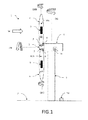
- Fig. 1 shows an embodiment of a wind turbine 1 according to the invention with pitch control consisting of several components comprising a tower 3, which carries the other components of the wind turbine and is anchored in the ground 2.
- a tower 3 which carries the other components of the wind turbine and is anchored in the ground 2.
- a gondola 4 rotatably mounted on the tower 3 about a rotation axis DG
- a rotor 5 with a hub 5 rotatably mounted on the nacelle 4 about a rotation axis DN and at least two rotor blades 6 supported in the hub 5
- the wind turbine 1 may comprise two rotor blades 6 or three rotor blades 6, wherein in the latter case the third rotor blade 6 is covered by the hub 5.
- the rotor blades 6 have in the wind W depending on the angle of attack to wind W buoyancy for rotating the rotor about the axis of rotation DN, each rotor blade 6 about its longitudinal axis (rotational axis DRB) is rotatably mounted in the hub 5, so that the angle of attack of each rotor blade 6 relative can be set to the wind W each by means of a pitch motor 7.
- Each of the rotor blades 6 here has a pitch motor 7, wherein the pitch motors 7 are arranged in the hub 5 and are provided from one or more also arranged in the hub 5 energy storage 8 with electrical energy.
- the pitch motors 7 and energy storage 8 rotate with the hub 5 in wind operation. Suitable energy stores are, for example, batteries or ultra-capacitors.
- all the energy storage devices 8 can be charged in parallel by the photovoltaic cells.
- only one energy storage 8 for the operation of a pitch motor 7 can be charged by the photovoltaic cells 9.
- the charging AR of the energy storage 8 for the pitch motors 7 in idle mode with several energy storage devices 8 can take place successively for each energy storage device 8, until at the end all energy storage devices are charged.
- the photovoltaic cells 9 are connected by means of electrical cable within the rotor blades 6 with the energy storage 8 directly or indirectly via the pitch motors 7.
- the advantage here is the easy-to-design electrical connection of the photovoltaic cells 9 with the energy storage 8, since all components do not move relative to each other.
- the rotation of the rotor blades 6 along the axis of rotation DRB is no obstacle, since the cable connections can be designed so flexible that rotations of the rotor blades by +/- 180 degrees or more without modification of the cable connections are easily tolerated.
- the photovoltaic cells 9 are arranged in this embodiment on at least one outer side 61 of each of the rotor blades 6, wherein the rotor blades 6 include a leading edge and an edge adjacent wing portion 61 for generating the lift, which is particularly well suited for the attachment of one or more photovoltaic cells 9 in this wing area 61 is suitable.
- the wing region 61 has a first surface 61a and a second surface 61b opposite the first surface 61a, the one or more photovoltaic cells 9 in the first surface 61a (upper rotor blade) and in the second surface 61b (lower rotor blade ) are arranged.
- the wind turbine 1 further comprises a controller 10 for the rotor blades 6, which is designed so that the rotor blades 6 equipped with one or more photovoltaic cells 9 are brought into a position PB of the wind turbine 1 in the idle mode, which is responsible for generating electrical energy the photovoltaic cells 9 is particularly favorable, so at least for one of the rotor blades 6 at an angle with the highest possible solar radiation. Since the geographical position of the wind turbine and the local position of the sun are known as a function of the time, the control can be done according to a correspondingly stored in the control cam as a function of time.
- Fig.2 shows an alternative embodiment of a wind turbine 1 according to the invention, in which the photovoltaic cells 9 are arranged here instead of the rotor blades 6 here on the nacelle 4.
- An arrangement of the photovoltaic cells 9 on the nacelle 4 facilitates their maintenance, since the nacelle 4 is more accessible than, for example, the wing surfaces 61 of the rotor blades 6. Since the nacelle but not co-rotated with the energy storage 8, an additional slip ring for the electrical connection between photovoltaic cells 9 and energy storage 8 necessary if a permanent electrical connection to the photovoltaic cells is desired.
- FIG. 1 refer to the description FIG. 1 directed.
- the photovoltaic cells 9 are arranged here, for example, on both lateral outer sides 4a of the nacelle 4 (rear side of the nacelle 4 is not visible), so that the photovoltaic cells are arranged on two outer sides 4a of the nacelle 4 facing in different directions, one of which faces the outside of the sun , Alternatively, the photovoltaic cells 9 can also be arranged on the upper outer side 4b of the nacelle, which always receives solar radiation regardless of the position of the sun, but only at lunchtime from a particularly favorable angle (preferably vertical incidence of solar radiation on the surface of the photovoltaic cells).
- the wind energy installation 1 comprises a controller 10 for the rotatable nacelle 4, which is designed such that the rotatable nacelle 4 equipped with one or more photovoltaic cells 9 is brought to a position PB in idle operation of the wind energy installation 1, which is responsible for generation of electrical energy through the photovoltaic cells 9 is particularly favorable.
- the controller 10 is additionally designed so that the rotor blades 6 are stopped in idle mode in a position in which the shading of the photovoltaic cells 9 to the nacelle 4 by the rotor blades 6 is minimal. Since the geographical position of the wind turbine 1 is known and the local position of the sun is a function of the time, the controller can after a correspondingly stored in the control cam as a function of time, also for the position of the rotor blades done.
- FIG. 3 shows a further alternative embodiment of a wind turbine 1 according to the invention with photovoltaic cells 9 on the hub 5.
- the photovoltaic cells 5 arranged on the outside of the hub 5 pointing away from the nacelle 4 are arranged asymmetrically about the pivot point 51 of the hub 5.
- the hub as seen from the side views of the FIGS. 1 and 2 is visible, usually has a curved shape, the surface of the photovoltaic cells 9 in the direction of solar radiation (upward), provided that the hub 5 in the in FIG. 3 position comes to a halt.
- the photovoltaic cells 9 are arranged only in the upper, the solar radiation facing half of the hub 5 and therefore in a particularly favorable position for generating solar power.
- This position can be adjusted by a controller 10 for the hub 5, which is designed so that the equipped with one or more photovoltaic cell / n 9 hub 5 is brought in idle operation of the wind turbine 1 in this favorable position for the solar power generation PB.
- the photovoltaic cells 9 disposed on the outside of the hub 5 facing away from the nacelle 4 may be arranged symmetrically about the fulcrum of the hub 5, thus obviating control for proper positioning of the hub.
- a controller 10 for the alignment of the hub 5 to the sun by rotation of the nacelle 4 is provided about the axis of rotation DG.
- the controller 10 can be arranged in at least one of the rotatable components 4, 5, 6 or in the tower 3 or on the ground 2.
- the controller is suitably connected to the motors for rotating the rotatable components 4, 5, 6.
- Figure 4 1 shows a section of a rotor blade 6, which comprises a plurality of photovoltaic cells 9, which are arranged in recesses 62 in the wing region 61, wherein the recesses 62 suitably adapted to the shape of the photovoltaic cells 9 are.
- the photovoltaic cells with a transparent cover 91 (shown in gray) above the photovoltaic cells 9 (shown in phantom, as disposed below the cover) as part of the surface 61 a, 61 b of the wing portion 61 covered.
- the cover 62 must be at least largely transparent at least in the spectral range of the solar spectrum, the radiation of which is used for solar power generation by converting the solar energy into electrical energy.
- Suitable covers are known in the art.
- the own surfaces of the photovoltaic cells 9, the surface 61 a, 61 b of the wing portion 61, so that a cover, as in 4 (a) shown can be avoided.
- small-area photovoltaic cells 9 are particularly expedient in this exemplary embodiment, which are assembled to a corresponding total area with the required size for the generation of solar power.
- the examples shown also apply to an arrangement of the photovoltaic cells on the hub 5 or the nacelle 4.
- the surfaces 61 a shown would be the outer surface of the hub 5 or the nacelle 4.
- photovoltaic cells can also be mounted on the surfaces of the rotatable components 4, 5, 6, for example, the photovoltaic cells 9 can be glued to the respective surfaces.
- the photovoltaic cells 9 can be glued to the respective surfaces.
- only one hole would have to be provided for the passage of the electrical cables from the photovoltaic cells 9 into the interior of the rotatable components 4, 5, 6.
- This has the advantage that the total area of the photovoltaic cells can be arbitrarily varied within the available surfaces according to the power requirements for the pitch motors 7 and optionally for the power supply of other components and the power generation efficiency (position of the wind turbine, degree of solar radiation) without additional adaptation effort.
- Flexible photovoltaic cells are particularly suitable for bonded-on photovoltaic cells, since they also conform to curved surfaces, for example photovoltaic cells made of organic material.
- the advantage of photovoltaic cells arranged in corresponding recesses is that the Flow properties, for example, the rotor blades 6 and the hub 5 are not affected by the existing photovoltaic cells 9.
- a transparent cover 62 additionally protects the photovoltaic cells against external mechanical influences, for example hail or bird strike.
- photovoltaic cells whose surface simultaneously represents the surface of the rotors 6 or hub 5 (eg flexible photovoltaic cells), simplify the assembly of the photovoltaic cells.
- the size of the total area, which must be covered by photovoltaic cells 9 so that the necessary energy can be provided for charging the energy storage 8, results from the technical data of the respective wind turbine 1 and from the data for the solar radiation at the geographical location of the wind turbine 1. In Germany, for example, there is an average solar radiation of 650 - 1150 kWh per kW-peak and year. A typical photovoltaic system generates 1 kW peak for a total area of 10 m 2 . This results in an energy yield of 65 - 115 kWh per square meter photovoltaic cell area and year for Germany.
- High wind rotors have, for example, wing areas of up to or more than 1000 m 2 .
- Pitch motors 7 of a 6 MW wind turbines have, for example, a power of 7.5 kW per pitch motor 7, the pitch motor 7, for example, from a series connection of eighteen 12 V battery as energy storage 8, each with a capacity of 7.2 Ah or 12.0 Ah is fed.
- the self-discharge of such batteries is about 9% after 3 months.
- a photovoltaic system would therefore have to generate 78 Wh per month to compensate for the self-discharge of eighteen batteries, for which a total area of 16 cm 2 per battery to be supplied (including a 100% safety reserve) would be sufficient. With a total of eighteen batteries to be charged, the total area including a corresponding safety margin is then 300 cm 2 .
- the area should be equipped with photovoltaic cells correspondingly larger.
- photovoltaic cells correspondingly larger.
- ultra-capacitors the faster Show self-discharge as batteries, a minimum area of 25 cm 2 per supplied ultra-capacitor energy storage 8 would be sufficient, the total area then scaled with the number of ultra-capacitors used. If additional components of the wind turbine 1 are to be additionally supplied with electrical energy by the photovoltaic cells 9, the required total area would have to be correspondingly larger by the person skilled in the art.
- the photovoltaic cells 9 depending on the arrangement of the respective rotatable component and their level for solar radiation do not provide the average energy yield typical for Germany, but less. If, in addition, a safety margin is added to compensate for below-average energy yields, then total areas for photovoltaic cells 9 even below 1 m 2 would be usable for charging the energy stores for the pitch motors. In addition, unfavorable climatic conditions during operation of the wind turbine 1 can cause a faster self-discharge of the energy storage, which also leads to a larger surface to be dimensioned of the photovoltaic cells. Similarly, the deviations of the average solar radiation from the values typical for Germany when operating the wind energy plants at another geographical location must be taken into account.
- FIG. 5 shows an embodiment of a method according to the invention for charging the energy storage 8 of the pitch motors 7 of a wind turbine 1 according to the invention.
- the method comprises the steps of charging AW all energy storage 8 (dashed arrow) for the pitch motors 7 during wind operation (suitable wind available: "J") the wind turbine 1 by means of the energy generated by the wind turbine 1 WE.
- the energy storage devices can also be charged by a connected power grid and / or by means of the solar power generated by the photovoltaic cells 9 during wind operation.
- the energy storage device (s) charged in this way are, at a desired end of the quiescent operation, able to supply the pitch motors with the necessary energy for rotating the rotor blades 6, so that an angle of attack suitable for the wind operation for at least one of the rotor blades 6 by the pitch motors 7 can be adjusted.
- the energy storage devices 8 can be charged again from wind energy WE.
- the method preferably comprises the additional step that the controller 10 of the wind energy installation 1 for the rotatable components 4, 5, 6 brings the rotatable components 4, 5, 6 equipped with one or more photovoltaic cells 9 into a position PB in the idle mode of the wind power installation 1, which is particularly favorable for a generation of electrical energy by the photovoltaic cells 9.
Abstract
Description
Die Erfindung bezieht sich auf eine Windenergieanlage mit Pitchregelung, die mit einer oder mehreren Photovoltaikzellen zur Energieversorgung der Pitchmotoren ausgestattet ist, auf eine drehbare Komponente der Windenergieanlage, die mit einer oder mehreren Photovoltaikzellen zur Energieversorgung der Pitchmotoren ausgestattet ist, sowie auf ein Verfahren zum Betreiben einer solchen Windenergieanlage.The invention relates to a wind energy plant with pitch control, which is equipped with one or more photovoltaic cells for powering the pitch motors, to a rotatable component of the wind turbine, which is equipped with one or more photovoltaic cells for powering the pitch motors, and to a method for operating a such a wind turbine.
Windenergieanlagen wandeln mit ihren Rotoren die Windenergie in elektrische Energie zur Einspeisung in ein Stromnetz um. Die Rotoren besitzen dazu mindestens ein Rotorblatt, wobei die meisten Windenergieanlagen einen Rotor mit jeweils drei Rotorblättern besitzen. Eine Windenergieanlage besteht im Wesentlichen aus einem Rotor mit Nabe und Rotorblättern sowie einer Maschinengondel, die den Generator und häufig ein Getriebe beherbergt. Die Gondel ist drehbar auf einem Turm gelagert, dessen Fundament die notwendige Standsicherheit gibt. Je nach Windrichtung wird die Gondel so in den Wind gedreht, dass entsprechend viel Windenergie über die Drehung des Rotors im Generator in elektrische Energie umgewandelt werden kann.Wind turbines use their rotors to convert wind energy into electrical energy for feeding into a power grid. The rotors have for this purpose at least one rotor blade, with most wind turbines having a rotor with three rotor blades. A wind turbine essentially consists of a rotor with hub and rotor blades and a nacelle, which houses the generator and often a gearbox. The nacelle is rotatably mounted on a tower whose foundation gives the necessary stability. Depending on the wind direction, the nacelle is turned into the wind so that a corresponding amount of wind energy can be converted via the rotation of the rotor in the generator into electrical energy.
Die Windenergieanlagen werden von einer Regelelektronik bei ertragsversprechenden Windgeschwindigkeiten größer einer Anlaufgeschwindigkeit angefahren und bei zu großen Windgeschwindigkeiten größer einer Abschaltgeschwindigkeit wieder abgeschaltet. Die Windgeschwindigkeit kann dabei von der Steuerung über ein Anemometer ermittelt oder aus der Drehzahl des Rotors und der abgegebenen Leistung abgeleitet werden. Eine Abschaltung der Windenergieanlagen kann auch durch einen fehlenden Netzanschluss bzw. durch eine Netzstörung verursacht werden. Sogenannte pitchgeregelte Windenergieanlagen stellen heute den Stand der Technik dar. Das Drehen der Rotorblätter in den bzw. aus dem Wind wird dabei "Pitchen" genannt. Damit die Rotorblätter gedreht werden können, sind diese in der Nabe drehbar gelagert und werden von einem Pitchmotor in die gewünschte Stellung gedreht. Die Rotorblätter besitzen dabei je nach Anstellwinkel zum Wind einen größeren oder kleineren Auftrieb, der den Rotor in Drehung versetzt. Durch eine Pitchregelung kann der Rotor auch angehalten werden, indem die Rotorblätter in eine Position gedreht werden, die den Rotor auch bei Wind bis zum Stillstand abbremst. Soll der Rotor im Stillstand verweilen, wird der Anstellwinkel der Rotorblätter so gewählt, dass die Rotorblätter keinen Auftrieb durch den Wind erfahren. Solange die Windenergieanlage elektrische Energie erzeugt, kann sie selbständig die Pitchmotoren mit Energie versorgen. Problematisch ist es allerdings, wenn die Windenergieanlage vom Netz genommen wird. In diesem Fall wird der Anstellwinkel der Rotorblätter so verstellt, dass die Windenergieanlage keine elektrische Energie erzeugt. Damit ist eine Rückstellung der Rotorblätter in den Wind allerdings wegen des fehlenden Windes nicht mehr möglich. Damit Windenergieanlagen dennoch von einem Ruhebetrieb (Betrieb, bei dem keine elektrische Energie aus der Windenergie erzeugt wird) in den Windbetrieb (Erzeugung elektrischer Energie aus der Windenergie) geschaltet werden kann, müssen die Pitchmotoren weiterhin mit Energie versorgt werden. Die Druckschrift
Dokument
Es ist eine Aufgabe der vorliegenden Erfindung, eine kosten- und wartungsgünstige Windenergieanlage und entsprechende Komponenten der Windenergieanlage zur Verfügung zu stellen, die eine kompakte Anordnung von Energiespeicher und Pitchmotoren ermöglicht und die die Pitchmotoren selbst nach langer Standzeit des Rotors mit der notwendigen Energie zur Verstellung des Anstellwinkels der Rotorblätter versorgen kann.It is an object of the present invention to provide a low cost and low maintenance wind turbine and corresponding components of the wind turbine, which allows a compact arrangement of energy storage and pitch motors and the pitch motors even after a long life of the rotor with the necessary energy to adjust the Can supply pitch of the rotor blades.
Diese Aufgabe wird gelöst durch eine Windenergieanlage mit Pitchregelung aus mehreren Komponenten umfassend einen Turm, eine drehbar auf dem Turm angeordnete Gondel, einen an der Gondel drehbar befestigten Rotor mit Nabe und mindestens ein in der Nabe gehaltertes Rotorblatt, das im Wind einen vom Anstellwinkel zum Wind abhängigen Auftrieb zum Drehen des Rotors besitzen, wobei jedes Rotorblatt um seine Längsachse drehbar in der Nabe gelagert ist und der Anstellwinkels jedes Rotorblatts relativ zum Wind jeweils mittels eines in der Nabe oder im Rotorblatt angeordneten Pitchmotors eingestellt werden kann, wobei der Pitchmotor aus einem oder mehreren Energiespeichern mit elektrischer Energie vorsorgt werden kann und mindestens eine der drehbaren Komponenten mit einer oder mehreren Photovoltaikzellen ausgestattet ist, die so mit mindestens einem der Energiespeicher verbunden sind, dass die ein oder mehreren Photovoltaikzellen zumindest den Energiespeicher für den Pitchmotor mit elektrischer Energie versorgen können.This object is achieved by a wind turbine with pitch control of several components comprising a tower, a rotatably mounted on the tower nacelle, rotatably mounted on the nacelle rotor with hub and at least one held in the hub rotor blade, in the wind one of the angle of attack to the wind each rotor blade is mounted rotatably about its longitudinal axis in the hub and the angle of attack of each rotor blade relative to the wind can each be adjusted by means of a arranged in the hub or in the rotor blade pitch motor, the pitch motor of one or more Energy storage can be provided with electrical energy and at least one of the rotatable components is equipped with one or more photovoltaic cells, which are connected to at least one of the energy storage, that one or more Photovoltaic cells can supply at least the energy storage for the pitch motor with electrical energy.
Eine Windenergieanlage (oder auch Windkraftanlage) wandelt die Energie des Windes in elektrische Energie um und speist sie gewöhnlich in ein angeschlossenes Stromnetz ein. Windenergieanlagen können dabei an Land oder als sogenannte Offshore-Anlagen im Bereich moderater Wassertiefen vor der Küste angeordnet werden. Windenergieanlagen an Land liefern typischerweise bis zu 3MW an elektrischer Energie, sogenannte Offshore-Anlagen können dagegen bis zu 6MW an elektrischer Energie liefern, da sie aufgrund der gegenüber dem Landbetrieb geringeren Restriktionen bzgl. Höhe und Rotorgröße und des höheren Windangebots größer beziehungsweise leistungsstärker sein können. Dafür ist der Wartungsaufwand für Offshore-Anlagen aufgrund ihrer erschwerten Erreichbarkeit höher. Gerade für solche Windenergieanlagen ist ein Betrieb mit möglichst geringem Wartungsaufwand wichtig. Windenergieanlagen können ein einzelnes Rotorblatt oder mehrere Rotorblätter beispielsweise zwei, drei oder vier Rotorblätter umfassen. Typischerweise umfassen Windenergieanlagen drei Rotorblätter, da hier die Lagerung der Nabe und des Rotors am günstigsten zu gestalten ist.A wind turbine (or wind turbine) converts the energy of the wind into electrical energy and usually feeds it into a connected power grid. Wind turbines can be arranged on land or as so-called offshore installations in the area of moderate depths off the coast. Onshore wind turbines typically deliver up to 3MW of electrical energy, while so-called offshore installations can deliver up to 6MW of electrical energy since they may be larger or more powerful due to the lower restrictions on land height, rotor size, and higher wind supply. For the maintenance of offshore installations is higher because of their difficult accessibility. Especially for such wind turbines, operation with the least possible maintenance is important. Wind turbines may comprise a single rotor blade or a plurality of rotor blades, for example two, three or four rotor blades. Typically, wind turbines include three rotor blades, since here the storage of the hub and the rotor is most favorable.
Eine Windenergieanlage umfasst dabei einen Turm zur Halterung der drehbaren Komponenten. Die minimale Höhe des Turms wird unter anderem vom Rotordurchmesser bestimmt. Als Rotordurchmesser wird dabei der Durchmesser der Fläche bezeichnet, innerhalb der die Rotorblätter im Wind rotieren. Windenergieanlagen können sehr unterschiedliche Rotordurchmesser bis mehr als 120m besitzen. Aufgrund der lokalen Windströmungen liefern Anlagen an Land mit höheren Türmen zudem höhere Energien im Vergleich zu Landanlegen mit kleineren Türmen. Auf dem Turm ist eine Gondel drehbar gelagert, wobei die Drehachse der Gondel (Gondel-Drehachse) in der Regel senkrecht zur Erdoberfläche steht. In der Gondel ist der Rotor mit Nabe und Rotorblättern gelagert und mit einem Generator zur Stromerzeugung verbunden. Die Gondel wird daher auch als Maschinengondel bezeichnet. Die Gondel kann zusätzlich ein Getriebe umfassen. Mittels Drehung der Gondel können die Rotorblätter in die günstigste Position zum Wind gebracht werden. Die Windrichtungsnachführung erfolgt bespielsweise durch Stellmotoren, wobei die Windrichtung über sogenannte Windgebungssensoren ermittelt wird. Die elektrische Anbindung der Gondel an das Stromnetz erfolgt in der Regel über fest mit der Gondel verbundene Kabel. Die Nabe bezeichnet den Teil des Rotors, der drehbar auf gleicher Höhe vor der Gondel angeordnet ist und in dem die Rotorblätter befestigt sind. Die Drehachse des Rotors und damit auch der Nabe und der an ihr befestigten Rotorblätter im Windbetrieb steht im Wesentlichen senkrecht zur Gondel-Drehachse. In der Nabe sind für die Drehung des Rotors zur Erzeugung von elektrischer Energie aus der Windenergie ein oder mehrere Rotorblätter gehaltert. Das Rotorblatt ist dabei so geformt, dass der auf das Rotorblatt auftreffende Wind einen Auftrieb für das Rotorblatt erzeugt, so dass der Rotor infolge des Auftriebs der Rotorblätter in Drehung versetzt wird. Moderne Rotorblätter besitzen eine flügelähnliche Form und sind in der Regel aus glasfaserverstärktem Kunststoff oder Kohlestofffasern gefertigt. Um eine Eisbildung auf den Rotorblättern zu verhindern, können Rotorblätter eine Rotorblattheizung besitzen. Eine solche Rotorblattheizung kann beispielsweise eine Leistung von einigen kW besizen. Die Stärke des Auftriebs für die Rotorblätter hängt von deren Anstellwinkel zum Wind ab. Der Anstellwinkel bezeichnet hierbei den Winkel zwischen der Windrichtung und der Oberfläche des flügelförmigen Teils der Rotorblätter. Je nach Bedarf an elektrischer Energie und Stärke des Windes können unterschiedliche Anstellwinkel gewünscht werden. Daher ist das Rotorblatt um seine Längsachse drehbar in der Nabe gelagert. Der einstellbare Anstellwinkel kann außerdem zum Anhalten (Bremsen) und Starten (Beginn der Drehung) des Rotors verwendet werden. Bei für die Energieerzeugung geeigneten Windgeschwindigkeiten wird der vormals stehende Rotor angefahren, bei zu großen Windgeschwindigkeiten wird die Windenergieanlage zum Schutz der Anlage abgeschaltet und der Rotor angehalten. Die Windgeschwindigkeit kann dabei über ein Anemometer ermittelt und mit einer entsprechenden Steuerung eine Drehung ("Pitchen") der Rotorblätter entsprechend der ermittelten Windgeschwindigkeit vorgenommen werden. Die Drehung der Rotorblätter erfolgt über einen sogenannten Pitchmotor, der innerhalb der Nabe angeordnet ist. Die Abbremsung der Anlage kann beispielsweise über einen entsprechenden, die Drehung der Rotorblätter bremsenden Anstellwinkel erreicht oder unterstützt werden. Ist die Windgeschwindigkeit zu gering für einen wirtschaftlichen Betrieb der Anlage oder soll der Rotor im Ruhebetrieb (oder Stillstandsbetrieb) der Windenergieanlage nicht rotieren, wird der Anstellwinkel auf eine Null-Grad-Position zum Wind (Segelstellung) gebracht. Die Veränderung des Anstellwinkels der Rotorblätter durch die Pitchmotoren als Reaktion auf die vorhandenen Windgeschwindigkeiten und den Erzeugungsbedarf an elektrischer Energie wird auch als Pitchregelung bezeichnet. Neben der Gondel, der Nabe, dem Rotor und dem oder den Rotorblättern als den drehbaren Komponenten kann eine Windenergieanlage noch weitere drehbare Komponenten umfassen.A wind energy plant comprises a tower for holding the rotatable components. The minimum height of the tower is determined inter alia by the rotor diameter. The rotor diameter is the diameter of the surface within which the rotor blades rotate in the wind. Wind turbines can have very different rotor diameters up to more than 120m. Due to the local wind currents, land-based turbines with higher towers also provide higher energy than land-based systems with smaller towers. On the tower a nacelle is rotatably mounted, wherein the axis of rotation of the nacelle (nacelle axis of rotation) is usually perpendicular to the earth's surface. In the nacelle, the rotor is mounted with hub and rotor blades and connected to a generator for power generation. The nacelle is therefore also referred to as a nacelle. The nacelle may additionally comprise a transmission. By rotating the nacelle, the rotor blades in the most favorable position to the wind. The wind direction tracking takes place recordable by servo motors, the wind direction is determined by so-called Windgebungssensoren. The electrical connection of the nacelle to the power grid is usually via permanently connected to the nacelle cables. The hub refers to the part of the rotor which is rotatably arranged at the same height in front of the nacelle and in which the rotor blades are mounted. The axis of rotation of the rotor and thus also the hub and the blades attached to it in wind operation is substantially perpendicular to the nacelle axis of rotation. In the hub, one or more rotor blades are supported for the rotation of the rotor for generating electrical energy from the wind energy. The rotor blade is shaped such that the wind impinging on the rotor blade generates a lift for the rotor blade, so that the rotor is set in rotation as a result of the buoyancy of the rotor blades. Modern rotor blades have a wing-like shape and are usually made of glass fiber reinforced plastic or carbon fibers. In order to prevent ice formation on the rotor blades, rotor blades may have a rotor blade heater. Such a rotor blade heater may, for example, have a power of a few kW. The strength of the buoyancy for the rotor blades depends on their angle of attack to the wind. The angle of attack here denotes the angle between the wind direction and the surface of the wing-shaped part of the rotor blades. Depending on the need for electrical energy and strength of the wind, different angles of attack may be desired. Therefore, the rotor blade is mounted rotatably about its longitudinal axis in the hub. The adjustable angle of attack can also be used for stopping (braking) and starting (starting to rotate) the rotor. At wind speeds suitable for power generation, the previously stationary rotor is approached; if the wind speeds are too high, the wind turbine is switched off to protect the system and the rotor is stopped. The wind speed can be determined via an anemometer and with a corresponding control a rotation ("pitching") of the rotor blades are made according to the determined wind speed. The rotation of the rotor blades via a so-called pitch motor, which is arranged within the hub. The deceleration of the system can be achieved or supported for example via a corresponding, the rotation of the rotor blades braking angle. If the wind speed is too low for economical operation of the plant or if the rotor is not intended to rotate in idle operation (or standstill operation) of the wind turbine, the angle of attack is brought to a zero-degree position to the wind (feathering). The change in the angle of attack of the rotor blades by the pitch motors in response to the existing wind speeds and the generation requirement of electrical energy is also referred to as pitch control. In addition to the nacelle, the hub, the rotor and the rotor blade (s) as the rotatable components, a wind energy plant may comprise further rotatable components.
Damit die Pitchmotoren mit der notwendigen elektrischen Energie versorgt werden, sind sie mit einem oder mehreren Energiespeichern als Energiequelle verbunden. Solche Energiespeicher können beispielsweise Batterien oder Super-Kondensatoren sein. Damit die elektrische Verbindung zu den Pitchmotoren vereinfacht und ein elektrischer Schleifring zur Kontaktierung nicht-rotierender Komponenten vermieden werden kann, sind sowohl die Pitchmotoren als auch die Energiespeicher auf oder in der Nabe oder auf dem Rotor montiert, so dass sowohl die Pitchmotoren als auch die Energiespeicher während des Betriebs der Windenergieanlage mit der Nabe mitrotieren. Im Gegensatz zu nichtmitrotierenden Energiespeichern kann ein Schleifring zur elektrischen Kontaktierung der Pitchmotoren vermieden werden.In order for the pitch motors to be supplied with the necessary electrical energy, they are connected to one or more energy stores as an energy source. Such energy storage can be, for example, batteries or super-capacitors. So that the electrical connection to the pitch motors simplified and an electrical slip ring for contacting non-rotating components can be avoided, both the pitch motors and the energy storage are mounted on or in the hub or on the rotor, so that both the pitch motors and the energy storage rotate during operation of the wind turbine with the hub. In contrast to nonmitrotierenden energy storage, a slip ring for electrical contacting of the pitch motors can be avoided.
Die Pitchmotoren können während des Windbetriebs (Erzeugung von elektrischer Energie aus der Windenergie) beispielsweise aus einem Teil der erzeugten elektrischen Energie gespeist werden. Diese Energiequelle ist allerdings bei Stillstand der Windenergieanlage, beispielsweise aufgrund von Windflaute oder einer Abschaltung der Windenergieanlege aufgrund zu starkem Wind oder aufgrund eines Netzausfalls nicht vorhanden. Sollte ein solcher Stillstandsbetrieb (Ruhebetrieb) längere Zeit andauern, wären die Energiespeicher zum Betrieb der Pitchmotoren aufgrund ihrer Selbstentladung ohne weitere Maßnahmen so stark entladen, dass die Rotorblätter nicht mehr durch die Pitchmotoren in eine Stellung mit geeignetem Auftrieb zum Anfahren der Windenergieanlge gedreht werden können. Um diese Situation zu vermeiden, umfasst die erfindungsgemäße Windenergieanlage ein oder mehrere Photovoltaikzellen, die zumindest den einen oder mehrere der Energiespeicher für den oder die Pitchmotoren mit elektrischer Energie versorgen. Die Anzahl und Anordnung der Photovoltaikzellen ist dabei so gewählt, dass zumindest die Selbstentladung der Energiespeicher für die Pitchmotoren kompensiert werden kann. Der Begriff "Photovoltaikzelle" bezeichnet eine Anordnung oder eine Anlage, in der die Sonnenstrahlung in elektrische Energie umgewandelt wird. Eine Photovoltaikzelle wird auch als Solarzelle bezeichnet. Photovoltaikzellen zeichnen sich durch eine lange Lebensdauer von mehr als 20 Jahren aus und sind als dünne Module auf dem Markt erhältlich, so dass sie leicht an Oberflächen angebracht oder in Oberflächen integriert werden können. Die gewünschte Menge der von den Photovoltaikzellen erzeugten elektrischen Energie (Solarstrom) kann durch eine entsprechend groß gewählte Fläche bestückt mit Photovoltaikzellen bereitgestellt werden. Photovoltaikzellen zeichnen sich dadurch aus, dass sie modular zu einem gemeinsamen Photovoltaikmodul / -anlage aus ein oder mehreren Photovoltaikzellen mit einer im Prinzip beliebig wählbaren Fläche verbunden werden können. Die Menge an Solarstrom, die die Phtovoltaikzellen in Summe liefern können, hängt neben der gemeinsamen Fläche der Photovoltaikzellen von deren Ausrichtung zur Sonne und der wetterbedingten Sonneneinstrahlung ab. Der Fachmann ist in der Lage, die Größe der gemeinsamen Fläche der Photovoltaikzellen an den Bedarf an elektrischer Energie aus Solarenergie anzupassen. Eine besonders günstige Ausrichtung der Photovoltaikzellen zur Sonne bezeichnet einen Winkel zwischen der Sonneneinstrahlungsrichtung und der Oberfläche der Photovoltaikzellen, der möglichst nahe an 90 Grad liegt. Dieser Winkel sollte für eine effektive Erzeugung von Solarenergie möglichst 30 Grad nicht unterschreiten.The pitch motors can be fed during wind operation (generation of electrical energy from wind energy), for example, from a part of the generated electrical energy. However, this energy source is not available when the wind turbine is at a standstill, for example due to a lack of wind or a shutdown of the wind energy due to excessive wind or due to a power failure. Should such a standstill operation (idle operation) continue for a longer time, the energy storage devices for operating the pitch motors would be so heavily discharged due to their self-discharge without further measures that the rotor blades are no longer moved by the pitch motors into one position can be rotated with suitable buoyancy for starting the wind turbine. In order to avoid this situation, the wind power installation according to the invention comprises one or more photovoltaic cells which supply at least one or more of the energy stores for the pitch motor (s) with electrical energy. The number and arrangement of the photovoltaic cells is chosen so that at least the self-discharge of the energy storage for the pitch motors can be compensated. The term "photovoltaic cell" refers to an arrangement or installation in which the solar radiation is converted into electrical energy. A photovoltaic cell is also called a solar cell. Photovoltaic cells have a long life span of more than 20 years and are available as thin modules on the market so that they can be easily attached to surfaces or integrated into surfaces. The desired amount of electrical energy generated by the photovoltaic cells (solar power) can be provided by a correspondingly large selected area equipped with photovoltaic cells. Photovoltaic cells are characterized in that they can be modularly connected to a common photovoltaic module / system of one or more photovoltaic cells with a basically arbitrary selectable surface. The amount of solar power which the photovoltaic cells can supply in total depends not only on the common area of the photovoltaic cells, but also on their orientation to the sun and the weather-related insolation. The person skilled in the art is able to adapt the size of the common area of the photovoltaic cells to the demand for electrical energy from solar energy. A particularly favorable orientation of the photovoltaic cells to the sun denotes an angle between the solar irradiation direction and the surface of the photovoltaic cells, which is as close as possible to 90 degrees. This angle should not be less than 30 degrees for effective generation of solar energy.
Mit der Energieversorgung der Energiespeicher mittels Photovoltaikzellen ist stets ein voller Ladezustand zumindest für einen der Energiespeicher sichergestellt, so dass der oder die Pitchmotoren selbst nach langer Standzeit des Rotors und fehlender Netzverbindung mit der notwendigen Energie zur Verstellung des Anstellwinkels der Rotorblätter versorgen können. Damit kann auch ein Energiespeicher mit entsprechend kleinerer Kapazität für den Betrieb der Pitchmotoren gewählt werden, da der oder die Energiespeicher aufgrund der zur Aufladung angeschlossenen Photovoltaikzellen stets vollgeladen ist/sind. Eine weitere Stromversorgung der Pitchmotoren von außerhalb, beispielsweise durch das Stromnetz ist nicht notwendig, da die Energiespeicher durch die Photovoltaikzellen mit ausreichender Energie für ein Anfahren der Windenergieanlage versorgt werden. Dadurch werden eine kosten- und wartungsgünstige Windenergieanlage und entsprechende Komponenten der Windenergieanlage zur Verfügung gestellt, die eine kompakte Anordnung von Energiespeicher und Pitchmotoren ermöglichen.With the energy supply of the energy storage means of photovoltaic cells, a full state of charge is always ensured at least for one of the energy storage, so that the pitch or the pitch motors even after a long life of the rotor and lack of network connection with the necessary energy for adjusting the Supply angle of the rotor blades can supply. Thus, an energy storage with a correspondingly smaller capacity for the operation of the pitch motors can be selected, since the one or more energy storage is always fully charged due to the photovoltaic cells connected to charge the / are. A further power supply of the pitch motors from outside, for example by the power grid is not necessary because the energy storage are powered by the photovoltaic cells with sufficient energy for starting the wind turbine. As a result, a low-cost and low-maintenance wind power plant and corresponding components of the wind power plant are made available, which enable a compact arrangement of energy storage and pitch motors.
In einer Ausführungsform sind die Photovoltaikzellen an zumindest einer Außenseite des Rotorblatts oder bei mehreren Rotorblättern an zumindest einer Außenseite eines der Rotorblätter und/oder an einer von der Gondel wegzeigenden Außenseite der Nabe angeordnet. In einer bevorzugten Ausführungsform mit mehreren Rotorblättern sind die Photovoltaikzellen an zumindest einer Außenseite jedes der Rotorblätter angeordnet. Die Anordnung kann aber auch an beiden Seiten jedes Rotorblatts erfolgen. Die Außenseite bezeichnet hier die Seite des Rotorblatts, die zumindest in einer geeigneten Stellung des Rotorblatts von der Sonne beschienen werden kann. In einer weiteren Ausführungsform umfasst das Rotorblatt eine vordere Kante und einen an die Kante anschließenden Flügelbereich zur Erzeugung des Auftriebs, wobei die eine oder mehrere Photovoltaikzellen in dem Flügelbereich angeordnet sind. Die Anordnung der Photovoltaikzelle/n an zumindest einer Außenseite des oder der Rotorblätter ist vorteilhaft, da diese eine große Fläche insbesondere im Flügelbereich besitzen und somit ausreichend Platz für die Anordnung von Photovoltaikzellen mit einer geeigneten Mindest-Gesamtfläche besitzen. Im Falle eines Rotors mit drei Rotorblättern, die jeweils mit Photovoltaikzellen ausgestattet sind, steht zumindest die Außenfläche eines der Rotorblätter in einem für die Solarstromerzeugung durch die Photovoltaikzellen besonders günstigen Winkel zur Sonne beziehungsweise zur Sonneneinstrahlung.In one embodiment, the photovoltaic cells are arranged on at least one outer side of the rotor blade or in the case of a plurality of rotor blades on at least one outer side of one of the rotor blades and / or on an outer side of the hub pointing away from the nacelle. In a preferred embodiment with a plurality of rotor blades, the photovoltaic cells are arranged on at least one outer side of each of the rotor blades. The arrangement can also take place on both sides of each rotor blade. The outside here refers to the side of the rotor blade, which can be illuminated by the sun at least in a suitable position of the rotor blade. In a further embodiment, the rotor blade comprises a front edge and a wing region adjoining the edge for generating the buoyancy, wherein the one or more photovoltaic cells are arranged in the wing region. The arrangement of the photovoltaic cell / s on at least one outer side of the rotor blades or is advantageous because they have a large area, especially in the wing area and thus have sufficient space for the arrangement of photovoltaic cells with a suitable minimum total area. In the case of a rotor with three rotor blades, which are each equipped with photovoltaic cells, at least the outer surface of one of the rotor blades is in an especially favorable for the solar power generation by the photovoltaic cells angle to the sun or sunlight.
In einer weiteren Ausführungsform umfasst die Außenseite der Rotorblätter oder der Nabe eine oder mehrere an die Größe und Form der Photovoltaikzellen angepassten Aussparung/en, in denen die eine oder mehrere Photovoltaikzelle/n angeordnet sind. Somit sind die Photovoltaikzellen nicht auf der Oberfläche angebracht, sondern in die Oberfläche integriert. Damit wird die Form der Außenseite der Rotorblätter nicht verändert, so dass die Rotorblätter weiterhin die ursprüngliche Form und damit die ursprünglichen Eigenschaften für die Erzeugung einer Auftriebskraft durch den Wind behalten. Die Aussparungen können beispielsweise oberhalb der Photovoltaikzellen (nach außen gewandt) mit einem für die Sonnenstrahlung in dem durch die Photovoltaikzellen nutzbaren Spektrum zumindest weitgehend transparenten Material verkleidet sein, so dass die äußere Form des Rotorblatts zur Beibehaltung seiner Ströumgseigenschaften der Form entspricht, die das Rotorblatt auch ohne die Photovoltaikzellen hätte. In einer bevorzugten Ausführungsform stellt/stellen die Oberfläche/n der ein oder mehreren Photovoltaikzellen im Bereich der Aussparung die Oberfläche des Rotorblatts oder der Nabe dar. Dadurch kann die voranstehend angeführte transparente Abdeckung vermieden werden.In another embodiment, the outer side of the rotor blades or the hub comprises one or more recesses / s adapted to the size and shape of the photovoltaic cells, in which the one or more photovoltaic cells are arranged. Thus, the photovoltaic cells are not mounted on the surface, but integrated into the surface. Thus, the shape of the outside of the rotor blades is not changed, so that the rotor blades continue to retain the original shape and thus the original properties for the generation of a buoyant force by the wind. The recesses can be clad, for example, above the photovoltaic cells (facing outward) with a material that is at least largely transparent to the solar radiation in the spectrum that can be used by the photovoltaic cells, so that the outer shape of the rotor blade to maintain its Ströumgseigenschaften corresponds to the shape of the rotor blade without the photovoltaic cells would have. In a preferred embodiment, the surface (s) of the one or more photovoltaic cells in the area of the recess represents the surface of the rotor blade or the hub. As a result, the above-mentioned transparent cover can be avoided.
In einer weiteren Ausführungsform besitzt der Flügelbereich eine erste Oberfläche und eine der ersten Oberfläche gegenüberliegende zweite Oberfläche, wobei die eine oder mehreren Photovoltaikzelle/n in der ersten und zweiten Oberfläche angeordnet sind. Somit ist unabhängig von der Stellung des Rotorblatts immer eine der Oberflächen der Sonne zugewandt, so dass es einer besonders geeignete Ausrichtung des Rotorblatts zur Sonne höchstens bei geringer Sonneneinstrahlung bedarf. Sind bei einem Rotor mit drei Rotorblättern alle Rotorblätter auf beiden (ersten und zweiten) Oberflächen mit Photovoltaikzellen ausgerüstet, kann auf eine besondere Ausrichtung der Rotorblätter zur Sonne verzichtet werden, da in einer beliebigen Stellung des Rotors immer eine Oberfläche eine günstige Stellung zur Sonneneinstrahlung besitzt. Zudem wirken sich Abschattungseffekte durch ein anderes schattenwerfendes Rotorblatt nicht negativ auf die Stromerzeugung durch die Photovoltaikzellen aus, da immer eine Oberfläche der Sonne besonders günstig zugewandt ist und damit nicht durch die anderen Rotorblätter abgeschattet werden kann.In another embodiment, the wing region has a first surface and a second surface opposite the first surface, wherein the one or more photovoltaic cells are disposed in the first and second surfaces. Thus, regardless of the position of the rotor blade, one of the surfaces always faces the sun, so that it requires a particularly suitable orientation of the rotor blade to the sun at most at low solar radiation. If a rotor with three rotor blades all rotor blades on both (first and second) surfaces equipped with photovoltaic cells, can be dispensed with a special orientation of the rotor blades to the sun, as in any position of the rotor always a surface has a favorable position to the sun. In addition, shading effects by another shadow-throwing rotor blade do not negatively affect the power generation by the photovoltaic cells, since always a surface of the sun is particularly favorable and thus can not be shaded by the other rotor blades.
In einer weiteren Ausführungsform sind die an der von der Gondel wegzeigenden Außenseite der Nabe angeordneten Photovoltaikzellen symmetrisch um den Drehpunkt der Nabe angeordnet. Dadurch wird sichergestellt, dass auch ohne Einstellung einer besonders günstigen Position der Nabe, deren Form in der Regel im Wesentlichen konisch ist, immer zumindest ein Teil der auf der Nabe angeordneten Photovoltaikzellen besonders günstig zur Sonne ausgerichtet sind.In a further embodiment, the photovoltaic cells arranged on the outside of the hub pointing away from the nacelle are arranged symmetrically about the pivot point of the hub. This ensures that even without setting a particularly favorable position of the hub, the shape of which is generally conical in the rule, always at least a portion of the arranged on the hub photovoltaic cells are particularly favorable to the sun.
In einer weiteren Ausführungsform sind die Photovoltaikzellen an mindestens einer Außenseite, vorzugsweise an mindestens zwei in unterschiedliche Richtungen weisenden Außenseiten, der Gondel angeordnet und mit den Energiespeichern für die Pitchmotoren oder mit den Pitchmotoren zumindest im Ruhebetrieb (nicht rotierender Rotor) elektrisch verbunden. Diese elektrische Verbindung kann im Windbetrieb unterbrochen sein, da die Energiespeicher dann über die aus der Windkraft gewonnene elektrische Energie versorgt werden können. Eine dauerhafte elektrische Verbindung zwischen Photovoltaikzellen und Energiespeicher kann beispielsweise über einen Schleifring erreicht werden.In a further embodiment, the photovoltaic cells are arranged on at least one outer side, preferably on at least two outer sides pointing in different directions, of the nacelle and electrically connected to the energy stores for the pitch motors or to the pitch motors at least in idle mode (non-rotating rotor). This electrical connection can be interrupted in wind operation, since the energy storage can then be supplied via the electrical energy obtained from the wind power. A permanent electrical connection between photovoltaic cells and energy storage can be achieved for example via a slip ring.
In einer bevorzugten Ausführungsform besitzt die Gondel zumindest in der Nähe der Nabe eine gekrümmte Außenseite und die Photovoltaikzellen sind in dem vom Erdboden wegzeigenden Bereich der gekrümmten Außenseite angeordnet. Somit sind zumindest ein Teil der Photovoltaikzellen in einem für die Solarstromerzeugung günstigen Winkel zur Sonne angeordnet.In a preferred embodiment, the nacelle has a curved outside at least in the vicinity of the hub, and the photovoltaic cells are arranged in the region of the curved outer side facing away from the ground. Thus, at least a part of the photovoltaic cells are arranged in an angle favorable to the solar power generation for the sun.
In einer weiteren Ausführungsform umfasst die Windenergieanlage eine Steuerung für die drehbaren Komponenten, die so ausgelegt ist, dass die mit einer oder mehreren Photovoltaikzellen ausgestatten drehbaren Komponenten im Ruhebetrieb der Windenergieanlage in eine Position gebracht werden, die für eine Erzeugung von elektrischer Energie durch die Photovoltaikzellen besonders günstig ist. Durch eine gezielte günstige Ausrichtung der Photovoltaikzellen zur Sonne kann einerseits die notwendige Fläche an Photovoltaikzellen zur Erzeugung der benötigten elektrischen Energie zur Aufladung der Energispeicher verringert werden, da bei dieser günstigen Ausrichtung pro Photovoltaikzelle mehr Solarenergie erzeugt wird als bei einer ungünstigen Ausrichtung. Andererseits brauchen nicht mehrere Rotorblätter und/oder die Gondel auf mehreren Seiten mit Photovoltaikzellen ausgestattet zu werden. In einer bevorzugten Ausführungsform sind dabei die an der von der Gondel wegzeigenden Außenseite der Nabe angeordneten Photovoltaikzellen asymmetrisch um den Drehpunkt der Nabe angeordnet. So kann die Anordnung der Photovoltaikzellen an oder auf der Nabe kompakter gestaltet werden, was die Fertigung der Nabe und die Montage der Photovoltaikzellen einfacher gestaltet.In a further embodiment, the wind turbine comprises a controller for the rotatable components, which is designed so that the rotatable components equipped with one or more photovoltaic cells are brought into a position in the idle mode of the wind turbine, which is particularly suitable for generating electrical energy by the photovoltaic cells is cheap. By a targeted favorable orientation of the photovoltaic cells to the sun, on the one hand, the necessary area of photovoltaic cells for generating the required electrical energy for charging the energy storage can be reduced, as in this favorable orientation per photovoltaic cell more Solar energy is generated as in an unfavorable orientation. On the other hand, multiple rotor blades and / or the gondola need not be equipped with photovoltaic cells on several sides. In a preferred embodiment, the photovoltaic cells arranged on the outside of the hub pointing away from the nacelle are arranged asymmetrically around the pivot point of the hub. Thus, the arrangement of the photovoltaic cells can be made more compact on or on the hub, which makes the production of the hub and the installation of the photovoltaic cells simpler.
In einer Ausführungsform ist die Steuerung der Windenergieanlage so ausgelegt, dass die Rotorblätter bei einer mit Photovoltaikzellen ausgestatteten Gondel im Ruhebetrieb in einer Position gestoppt werden, in der die Abschattung der Photovoltaikzellen an der Gondel durch die Rotorblätter minimal ist. Damit kann verhindert werden, dass die Erzeugung elektrischer Energie aus Sonnenenergie durch die Photovoltaikzellen an der Gondel bei optimaler Ausrichtung der Gondel zur Sonne nicht durch ungünstig stehende Rotorblätter gestört werden kann.In one embodiment, the control of the wind turbine is designed so that the rotor blades are stopped in a pod equipped with photovoltaic cells in idle mode in a position in which the shading of the photovoltaic cells on the nacelle by the rotor blades is minimal. This can be prevented that the generation of electrical energy from solar energy through the photovoltaic cells on the nacelle with optimal orientation of the nacelle to the sun can not be disturbed by unfavorable rotor blades.
Erfindungegemäße Windenergieanlagen können dabei mit Photovoltaikzellen an den Rotorblättern und/oder an der Nabe und/oder an der Gondel ausgestattet sein.Inventive wind turbines can be equipped with photovoltaic cells on the rotor blades and / or on the hub and / or on the nacelle.
Die Erfindung betrifft des Weiteren eine Komponente für die Verwendung als drehbare Komponente in einer Windenergieanlage mit Pitchregelung gemäß der vorliegenden Erfindung, die mit ein oder mehreren Photovoltaikzellen ausgestattet ist, die dazu vorgesehen sind, die Energiespeicher für die Pitchmotoren der Windenergieanlage mit elektrischer Energie aufzuladen. Da die einzelnen Komponenten von Windenergieanlagen separat vetrieben werden können, besteht ein Schutzbedürfnis auch für die einzelnen Komponenten.The invention further relates to a component for use as a rotatable component in a pitch-controlled wind turbine according to the present invention, which is equipped with one or more photovoltaic cells, which are intended to charge the energy storage for the pitch motors of the wind turbine with electrical energy. Since the individual components of wind turbines can be operated separately, there is also a need for protection for the individual components.
Die Erfindung betrifft des Weiteren ein Verfahren zum Betreiben einer Windenergieanlage mit Pitchregelung gemäß der vorliegenden Erfindung, umfassend die Schritte
- Aufladen der Energiespeicher für die Pitchmotoren während des Windbetriebs der Windenergieanlage mittels der durch die Windenergieanlage erzeugten Energie und/oder durch ein angeschlossenes Stromnetz und/oder mittels der durch die Photovoltaikzellen erzeugten Energie;
- Einstellen eines für den Ruhebetrieb geeigneten Anstellwinkels für jedes Rotorblatt mittels der Pitchmotoren;
- Aufladen von zumindest einem der Energiespeicher für die Pitchmotoren im Ruhebetrieb mittels der durch die Photovoltaikzellen erzeugten Energie; und
- Einstellen eines für den Windbetrieb geeigneten Anstellwinkels für zumindest eines der Rotorblätter durch die Pitchmotoren, die mit der nötigen Energie aus den mittels der Photovoltaikzellen aufgeladenen Energiespeichern gespeist werden.
- Charging the energy storage for the pitch motors during wind operation of the wind turbine by means of the energy generated by the wind turbine and / or by a connected power grid and / or by means of the energy generated by the photovoltaic cells;
- Setting a suitable for idle operation angle of attack for each rotor blade by means of the pitch motors;
- Charging at least one of the energy stores for the pitch motors in idle mode by means of the energy generated by the photovoltaic cells; and
- Setting a suitable angle for wind operation for at least one of the rotor blades by the pitch motors, which are fed with the necessary energy from the charged by means of photovoltaic cells energy storage.
Mit diesem Verfahren können Windenergieanlagen mit Energiespeichern mit entsprechend kleinerer Kapazität für den Betrieb der Pitchmotoren ausgestattet werden, da der oder die Energiespeicher aufgrund der zur Aufladung angeschlossenen Photovoltaikzellen stets vollgeladen ist/sind. Eine weitere Stromversorgung der Pitchmotoren von außerhalb, beispielsweise durch das Stromnetz ist nicht notwendig, da die Energiespeicher durch die Photovoltaikzellen mit ausreichender Energie für ein Anfahren der Windenergieanlage versorgt werden. Entsprechend braucht kein Schleifkontakt zwischen Rotor und Gondel zur Stromversorgung der Pitchmotoren beziehungsweise der Energiespeicher eingebaut zu werden. Dadurch wird ein kosten- und wartungsgünstiger Betrieb der erfindungsgemäßen Windenergieanlage mit einer kompakten Anordnung von Energiespeicher und Pitchmotoren ermöglicht.With this method, wind turbines can be equipped with energy storage with correspondingly smaller capacity for the operation of the pitch motors, since the one or more energy storage is always fully charged due to the photovoltaic cells connected for charging. A further power supply of the pitch motors from outside, for example by the power grid is not necessary because the energy storage are powered by the photovoltaic cells with sufficient energy for starting the wind turbine. Accordingly, no sliding contact between the rotor and nacelle for powering the pitch motors or the energy storage needs to be installed. As a result, a low-cost and low-maintenance operation of the wind power plant according to the invention with a compact arrangement of energy storage and pitch motors is made possible.
In einer Ausführungsform umfasst das Verfahren den zusätzlichen Schritt, dass eine Steuerung der Windkraftenergieanlage für die drehbaren Komponenten die mit ein oder mehreren Photovoltaikzellen ausgestatteten drehbaren Komponenten im Ruhebetrieb der Windkraftenergieanlage in eine Position bringt, die für eine Erzeugung von elektrischer Energie durch die Photovoltaikzellen besonders günstig ist. Durch diesen Verfahrensschritt kann die notwendige Fläche an Photovoltaikzellen zur Erzeugung der benötigten elektrischen Energie zur Aufladung der Energispeicher verringert werden, da bei dieser günstigen Ausrichtung zur Sonne pro Photovoltaikzelle mehr Solarenergie erzeugt wird als bei einer ungünstigen Ausrichtung.In one embodiment, the method includes the additional step of controlling the rotatable component wind power plant to place the rotatable components equipped with one or more photovoltaic cells at rest of the wind power plant at a position that is particularly favorable for generating electrical energy through the photovoltaic cells , By this process step, the necessary area Photovoltaic cells are reduced to generate the required electrical energy to charge the energy storage, since in this favorable orientation to the sun per photovoltaic cell more solar energy is generated than in an unfavorable orientation.
In einer weiteren Ausführungsform erfolgt der Schritt des Aufladens der Energiespeicher für die Pitchmotoren im Ruhebetrieb bei mehreren Energiespeichern sukzessive für jeden Energiespeicher. Die sukzessive Aufladung stellt sicher, dass nach kurzer Zeit zumindest ein Energiespeicher voll geladen für den Betrieb eines Pitchmotors zur Verfügung steht. Damit kann zumindest ein Rotorblatt so gedreht werden, dass es einen Auftrieb zur Drehung des Rotors besitzt. Damit kann der Rotor zumindest in leichte Rotation vesetzt werden, so dass die Windenergieanlage zumindest ausreichend Strom für die Aufladung der anderen Energiespeicher zum Betrieb der anderen Pitchmotoren erzeugt. Damit können unverzüglich auch die anderen Rotorblätter durch die Pitchmotoren gedreht und damit die Windenergieanlage zur Erzeugung elektrischer Energie zur Einspeisung in ein Stromnetz angefahren werden.In a further embodiment, the step of charging the energy store for the pitch motors in idle mode takes place successively for each energy store in the case of a plurality of energy stores. The successive charging ensures that after a short time at least one energy storage fully loaded for the operation of a pitch motor is available. Thus, at least one rotor blade can be rotated so that it has a buoyancy for rotation of the rotor. Thus, the rotor can be used at least in light rotation, so that the wind turbine generates at least sufficient power for the charging of the other energy storage for the operation of the other pitch motors. In order for the other rotor blades can be rotated by the pitch motors immediately and thus the wind turbine for generating electrical energy for feeding into a power grid are approached.
Diese und andere Aspekte der Erfindung werden im Detail in den Abbildungen wie folgt gezeigt.
- Fig.1:
- eine Ausführungsform einer erfindungsgemäßen Windenergieanlage mit Photovoltaikzellen an den Rotorblättern.
- Fig.2:
- eine alternative Ausführungsform einer erfindungsgemäßen Windenergieanlage mit Photovoltaikzellen an der Gondel.
- Fig.3:
- eine alternative Ausführungsform einer erfindungsgemäßen Windenergieanlage mit Photovoltaikzellen an der Nabe.
- Fig.4:
- Photovoltaikzellen angeordnet in geeigneten Aussparungen im Flügelbereich eines Rotor mit (a) einer transparenten Abdeckung der Photovoltaikzellen als Oberfläche des Flügelbereichs, und (b) mit Photovoltaikzellen, deren eigene Oberfläche die Oberfläche des Flügelbereichs bilden.
- Fig.5:
- eine Ausführungsform eines erfindungsgemäßen Verfahrens zum Aufladen der Energiespeicher der Pitchmotoren einer erfindungsgemäßen Windenergieanlage.
- Fig.1:
- An embodiment of a wind turbine according to the invention with photovoltaic cells on the rotor blades.
- Figure 2:
- an alternative embodiment of a wind turbine according to the invention with photovoltaic cells on the nacelle.
- Figure 3:
- an alternative embodiment of a wind turbine according to the invention with photovoltaic cells on the hub.
- Figure 4:
- Photovoltaic cells arranged in suitable recesses in the wing region of a rotor with (a) a transparent cover of the photovoltaic cells as the surface of the wing region, and (b) with photovoltaic cells whose surface is the surface of the rotor Form wing area.
- Figure 5:
- An embodiment of a method according to the invention for charging the energy storage of the pitch motors of a wind turbine according to the invention.
Für die Ausführungsformen gemäß der
Die Größe der Gesamtfläche, die von Photovoltaikzellen 9 bedeckt sein muss, damit die notwendige Energie zur Aufladung der Energiespeicher 8 bereitgestellt werden kann, ergibt sich aus den technischen Daten der jeweiligen Windenergieanlage 1 und aus den Daten für die Sonneneinstrahlung am geographischen Ort der Windenergieanlage 1. In Deutschland hat man beispielsweise eine durchschnittliche Sonneneinstrahlung von 650 - 1150 kWh pro kW-peak und Jahr. Eine typische Photovoltaikanlage erzeugt 1 kW-peak bei einer Gesamtfläche von 10 m2. Daraus ergibt sich für Deutschland ein Energieertrag von 65 - 115 kWh pro Quadratmeter Photovoltaikzellenfläche und Jahr. Starkwindrotoren haben beispielsweise Flügelflächen von bis zu oder mehr als 1000 m2. Pitchmotoren 7 einer 6 MW-Windenergieanlagen haben beispielsweise eine Leistung von 7,5 kW pro Pitchmotor 7, wobei der Pitchmotor 7 beispielsweise aus einer Reihenschaltung von achtzehn 12 V-Batterie als Energiespeicher 8 mit jeweils einer Kapazität von 7,2 Ah oder 12,0 Ah gespeist wird. Die Selbstentladung solcher Batterien beträgt ca. 9% nach 3 Monaten. Eine Photovoltaikanlage müsste daher zur Kompensation der Selbstentladung von achtzehn Batterien 78 Wh pro Monat erzeugen, wozu eine Gesamtfläche von 16 cm2 pro zu versorgender Batterie (inklusive einer 100% Sicherheitsreserve) ausreichend wäre. Bei einer Gesamtzahl von achtzehn zu ladenden Batterien beträgt die Gesamtfläche inklusive einer entsprechenden Sicherheitsreserve dann 300 cm2. Je nach Zykluszeit zwischen Windbetrieb und Ruhebetrieb und der Betriebsdauer der Pitchmotoren 7 im Ruhebetrieb der Windenergieanlage 1 aus den Energiespeichern 8 heraus müsste die Fläche ausgestattet mit Photovoltaikzellen entsprechend größer dimensioniert werden. Werden anstatt Batterien sogenannte Ultra-Kondensatoren verwendet, die eine schnellere Selbstentladung als Batterien zeigen, wäre eine Mindestfläche von 25 cm2 pro zu versorgendem Ultra-Kondensatoren-Energiespeicher 8 ausreichend, wobei die Gesamtfläche dann mit der Anzahl der verwendeten Ultra-Kondensatoren skaliert. Sollen weitere Komponenten der Windenergieanlage 1 zusätzlich mit elektrischer Energie durch die Photovoltaikzellen 9 versorgt werden, müsste die benötigte Gesamtfläche vom Fachmann entsprechend größer dimensioniert werden. Bei der Dimensionierung der Gesamtfläche der Photovoltaikzellen 9 ist ferner zu beachten, dass die Photovoltaikzellen 9 je nach Anordnung an der jeweiligen drehbaren Komponente und deren Stand zur Sonneneinstrahlung nicht den für Deutschland typischen durchschnittlichen Energieertrag liefern, sondern weniger. Wenn man zusätzlich einen Sicherheitsaufschlag zur Kompensation unterdurchschnittlicher Energieerträge hinzurechnet, so wären dennoch Gesamtflächen für Photovoltaikzellen 9 auch unterhalb von 1 m2 für die Aufladung der Energiespeicher für die Pitchmotoren verwendbar. Zusätzlich können ungünstige klimatische Bedingungen beim Betrieb der Windenergieanlage 1 eine schnellere Selbstentladung der Energiespeicher verursachen, was ebenfalls zu einer größer zu dimensionierenden Fläche der Photovoltaikzellen führt. Ebenso sind die Abweichungen der durchschnittlichen Sonneneinstrahlung von den für Deutschland typischen Werten bei einem Betrieb der Windenergieanlgae an einem anderen geographischen Ort zu berücksichtigen.The size of the total area, which must be covered by
Die hier gezeigten Ausführungsformen stellen nur Beispiele für die vorliegende Erfindung dar und dürfen daher nicht einschränkend verstanden werden. Alternative durch den Fachmann in Erwägung gezogene Ausführungsformen sind gleichermaßen vom Schutzbereich der vorliegenden Erfindung umfasst.The embodiments shown herein are only examples of the present invention and therefore should not be considered as limiting. Alternative embodiments contemplated by one skilled in the art are equally within the scope of the present invention.
- 11
- WindenergieanlageWind turbine
- 22
- Erdboden / ErdoberflächeSoil / earth surface
- 33
- Turm der WindenergieanlageTower of wind turbine
- 44
- Gondel der WindenergieanlageGondola of the wind turbine
- 4a4a
- seitliche Außenseite der Gondellateral outside of the gondola
- 4b4b
- obere Außenseite der Gondelupper outside of the gondola
- 55
- Nabe der WindenergieanlageHub of the wind turbine
- 66
- Rotorblatt der WindenergieanlageRotor blade of the wind energy plant
- 6161
- Flügelbereich des RotorblattsWing area of the rotor blade
- 61 a61 a
- erste Oberfläche des Flügelbereichsfirst surface of the wing area
- 61 b61 b
- zweite Oberfläche des Flügelbereichssecond surface of the wing area
- 6262
- Aussparung zur Montage von PhotovoltaikzellenRecess for mounting photovoltaic cells
- 77
- Pitchmotor für das RotorblattPitch motor for the rotor blade
- 88th
- Energiespeicher zur Energieversorgung des PitchmotorsEnergy storage for powering the pitch motor
- 99
- Photovoltaikzelle(n) / Modul aus mehreren PhotovoltaikzellenPhotovoltaic cell (s) / Module made up of several photovoltaic cells
- 9191
- transparente Abdeckung der Photovoltaikzellentransparent cover of the photovoltaic cells
- 1010
- Steuerung für die drehbaren Komponenten zur günstige Ausrichtung der Photovoltaikzelle(n)Control for the rotatable components for favorable alignment of the photovoltaic cell (s)
- ARAR
- Aufladen der Energiespeicher im RuhebetriebCharging the energy storage in idle mode
- AWAW
- Aufladen der Energiespeicher im WindbetriebCharging the energy storage in wind operation
- DGDG
- Drehachse der GondelRotary axle of the gondola
- DNDN
- Drehachse der NabeRotation axis of the hub
- DRDR
- Drehachse des Rotors / Rotorblätter durch den WindRotary axis of the rotor / rotor blades by the wind
- DRBDRB
- Drehachse des Rotorblatts zur Einstellung des Anstellwinkels mittels PitchmotorRotary axis of the rotor blade for adjusting the angle of attack by means of a pitch motor
- PBPB
- Positionieren der Nabe / Rotorblätter in einer günstigen Position zur Erzeugung von Solarstrom durch die PhotovoltaikzellenPositioning the hub / rotor blades in a favorable position to generate solar power through the photovoltaic cells
- WW
- geeigneter Wind zum Windbetriebsuitable wind for wind operation
- WEWE
- Windenergiewind energy
Claims (15)
dadurch gekennzeichnet,
dass die Photovoltaikzellen (9) an zumindest einer Außenseite (61) zumindest eines der Rotorblätter (6), vorzugsweise an zumindest einer Außenseite (61) jedes der Rotorblätter (6), und/oder an einer von der Gondel (4) wegzeigenden Außenseite der Nabe (5) angeordnet sind.The wind turbine (1) according to claim 1,
characterized,
in that the photovoltaic cells (9) are arranged on at least one outside (61) of at least one of the rotor blades (6), preferably on at least one outside (61) of each of the rotor blades (6), and / or on an outside of the gondola (4) Hub (5) are arranged.
dadurch gekennzeichnet,
dass die Außenseite (61) der Rotorblätter (6) oder der Nabe (5) eine oder mehrere an die Größe und Form der Photovoltaikzelle/n (9) angepassten Aussparungen (62) umfasst, in denen die eine oder mehreren Photovoltaikzellen (9) angeordnet sind; vorzugsweise stellen die Oberflächen der einen oder mehreren Photovoltaikzelle/n (9) im Bereich der Aussparungen (62) die Oberfläche (61 a, 61 b) des Rotorblatts (6) oder der Nabe (5) dar.The wind turbine (1) according to claim 2,
characterized,
in that the outside (61) of the rotor blades (6) or the hub (5) comprises one or more recesses (62) adapted to the size and shape of the photovoltaic cell (s) in which the one or more photovoltaic cells (9) are arranged are; Preferably, the surfaces of the one or more photovoltaic cell (s) (9) in the region of Recesses (62) the surface (61 a, 61 b) of the rotor blade (6) or the hub (5).
dadurch gekennzeichnet,
dass das Rotorblatt (6) eine vordere Kante und einen an die Kante anschließenden Flügelbereich (61) zur Erzeugung des Auftriebs umfasst, wobei die ein oder mehreren Photovoltaikzellen (9) in dem Flügelbereich (61) angeordnet sind.The wind turbine (1) according to claim 2 or 3,
characterized,
in that the rotor blade (6) comprises a front edge and a wing region (61) adjoining the edge for generating the lift, wherein the one or more photovoltaic cells (9) are arranged in the wing region (61).
dadurch gekennzeichnet,
dass der Flügelbereich (61) eine erste Oberfläche (61 a) und eine der ersten Oberfläche (61 a) gegenüberliegende zweite Oberfläche (61 b) besitzt, wobei die eine oder mehreren Photovoltaikzelle/n (9) in der ersten und zweiten Oberfläche (61 a, 61 b) angeordnet sind.The wind energy plant (1) according to claim 4,
characterized,
in that the wing region (61) has a first surface (61 a) and a second surface (61 b) opposite the first surface (61 a), wherein the one or more photovoltaic cells (n) in the first and second surfaces (61 a, 61 b) are arranged.
dadurch gekennzeichnet,
dass die an der von der Gondel (4) wegzeigenden Außenseite der Nabe (5) angeordneten Photovoltaikzellen (9) symmetrisch um den Drehpunkt der Nabe (5) angeordnet sind.The wind energy plant (1) according to one of claims 2 to 5,
characterized,
in that the photovoltaic cells (9) arranged on the outside of the hub (5) pointing away from the nacelle (4) are arranged symmetrically about the pivot point of the hub (5).
dadurch gekennzeichnet,
dass die Photovoltaikzellen (9) an mindestens einer Außenseite (4a, 4b), vorzugsweise an mindestens zwei in unterschiedliche Richtungen weisenden Außenseiten (4a, 4b), der Gondel (4) angeordnet sind und mit den Energiespeichern (8) für die Pitchmotoren (7) oder mit den Pitchmotoren (7) zumindest im Ruhebetrieb elektrisch verbunden sind.The wind energy plant (1) according to one of the preceding claims,
characterized,
in that the photovoltaic cells (9) are arranged on at least one outer side (4a, 4b), preferably on at least two outer sides (4a, 4b) facing the different directions, of the nacelle (4) and are connected to the energy stores (8) for the pitch motors (7 ) or electrically connected to the pitch motors (7) at least in idle mode.
dadurch gekennzeichnet,
dass die Gondel (4) zumindest in der Nähe der Nabe eine gekrümmte Außenseite (4a, 4b) besitzt und die Photovoltaikzellen (9) in dem vom Erdboden wegzeigenden Bereich der gekrümmten Außenseite (4a, 4b) angeordnet sind.The wind energy plant (1) according to claim 7,
characterized,
in that the nacelle (4) has a curved outer side (4a, 4b) at least in the vicinity of the hub and the photovoltaic cells (9) are arranged in the region of the curved outer side (4a, 4b) pointing away from the ground.
dadurch gekennzeichnet,
dass die Windenergieanlage (1) eine Steuerung (10) für die drehbaren Komponenten (4, 5, 6) umfasst, die so ausgelegt ist, dass die mit einer oder mehreren Photovoltaikzellen (9) ausgestatteten drehbaren Komponenten (4, 5, 6) im Ruhebetrieb der Windkraftenergieanlage (1) in eine Position gebracht (PB) werden, die für eine Erzeugung von elektrischer Energie durch die Photovoltaikzellen (9) besonders günstig ist.The wind energy plant (1) according to one of the preceding claims,
characterized,
in that the wind energy installation (1) comprises a control (10) for the rotatable components (4, 5, 6) which is designed in such a way that the rotatable components (4, 5, 6) equipped with one or more photovoltaic cells (9) Resting operation of the wind power plant (1) in a position (PB), which is particularly favorable for a generation of electrical energy by the photovoltaic cells (9).
dadurch gekennzeichnet,
dass die an der von der Gondel (4) wegzeigenden Außenseite der Nabe (5) angeordneten Photovoltaikzellen (5) asymmetrisch um den Drehpunkt (51) der Nabe (5) angeordnet sind.The wind energy plant (1) according to one of claims 9,
characterized,
in that the photovoltaic cells (5) arranged on the outside of the hub (5) pointing away from the nacelle (4) are arranged asymmetrically around the pivot point (51) of the hub (5).
dadurch gekennzeichnet,
dass die Steuerung (10) der Windenergieanlage (1) so ausgelegt ist, dass die Rotorblätter (6) bei einer mit Photovoltaikzellen (9) ausgestatteten Gondel (4) im Ruhebetrieb in einer Position gestoppt werden, in der die Abschattung der Photovoltaikzellen (9) an der Gondel (4) durch die Rotorblätter (6) minimal ist.The wind energy plant (1) according to claim 9,
characterized,
in that the control unit (10) of the wind energy installation (1) is designed so that the rotor blades (6) are stopped in a position equipped with photovoltaic cells (9) in a position in which the shading of the photovoltaic cells (9) is stopped. at the nacelle (4) by the rotor blades (6) is minimal.
dadurch gekennzeichnet,
dass der Schritt des Aufladens (AR) der Energiespeicher (8) für die Pitchmotoren (7) im Ruhebetrieb bei mehreren Energiespeichern (8) sukzessive für jeden Energiespeicher (8) erfolgt.A method according to claim 13 or 14,
characterized,
in that the step of charging (AR) of the energy stores (8) for the pitch motors (7) in idle mode takes place successively for each energy store (8) in the case of a plurality of energy stores (8).
Priority Applications (1)
| Application Number | Priority Date | Filing Date | Title |
|---|---|---|---|
| EP12165971.8A EP2657515A1 (en) | 2012-04-27 | 2012-04-27 | Wind energy assembly with pitch regulation |
Applications Claiming Priority (1)
| Application Number | Priority Date | Filing Date | Title |
|---|---|---|---|
| EP12165971.8A EP2657515A1 (en) | 2012-04-27 | 2012-04-27 | Wind energy assembly with pitch regulation |
Publications (1)
| Publication Number | Publication Date |
|---|---|
| EP2657515A1 true EP2657515A1 (en) | 2013-10-30 |
Family
ID=46052578
Family Applications (1)
| Application Number | Title | Priority Date | Filing Date |
|---|---|---|---|
| EP12165971.8A Withdrawn EP2657515A1 (en) | 2012-04-27 | 2012-04-27 | Wind energy assembly with pitch regulation |
Country Status (1)
| Country | Link |
|---|---|
| EP (1) | EP2657515A1 (en) |
Cited By (6)
| Publication number | Priority date | Publication date | Assignee | Title |
|---|---|---|---|---|
| WO2017190747A1 (en) * | 2016-05-04 | 2017-11-09 | Vestas Wind Systems A/S | In hub power generation and storage for anti-icing wind turbine blades |
| CN107905947A (en) * | 2017-11-02 | 2018-04-13 | 江苏燕山光伏设备有限公司 | A kind of solar wind force composite type power generator |
| CN110107451A (en) * | 2019-05-17 | 2019-08-09 | 杭州虹妍服饰有限公司 | A kind of wind turbine |
| CN111120220A (en) * | 2018-10-31 | 2020-05-08 | 北京金风科创风电设备有限公司 | Method and system for video monitoring of wind generating set blade |
| CN111509568A (en) * | 2020-04-30 | 2020-08-07 | 山东商务职业学院 | Electromechanical integrated power distribution cabinet protection device |
| US11936328B2 (en) | 2018-08-21 | 2024-03-19 | Vestas Wind Systems A/S | Method of operating a hybrid power plant to optimize PV power output |
Citations (9)
| Publication number | Priority date | Publication date | Assignee | Title |
|---|---|---|---|---|
| GB2187512A (en) * | 1985-11-08 | 1987-09-09 | Cecil Arthur Johnson | Combined solar power and wind power generator |
| US5254876A (en) * | 1992-05-28 | 1993-10-19 | Hickey John J | Combined solar and wind powered generator with spiral blades |
| DE202004007992U1 (en) * | 2004-05-18 | 2004-09-16 | Tönges, Gerd Otto | Combined wind and solar power unit for electric current production has solar cells on the tower blades and turbine housing surfaces |
| EP1961957A2 (en) | 2005-07-22 | 2008-08-27 | Gamesa Innovation & Technology, S.L. | Method of maintaining wind turbine components operational and a turbine comprising components suitable for operational maintenance |
| EP2108825A2 (en) * | 2008-04-01 | 2009-10-14 | General Electric Company | System and method for reducing rotor loads in a wind turbine upon detection of blade-pitch failure and loss of counter-torque |
| EP2146095A2 (en) | 2008-07-16 | 2010-01-20 | General Electric Company | Use of pitch battery power to start wind turbine during grid loss/black start capability |
| US20100320760A1 (en) * | 2009-06-22 | 2010-12-23 | POWER LIGHT Tech. Co., Ltd. | Solar and Wind Power Generator Capable of Tracking Sunlight Automatically |
| US20110031761A1 (en) * | 2008-01-25 | 2011-02-10 | Deangeles Steven J | Momentum-Conserving Wind-Driven Electrical Generator |
| US20110121575A1 (en) * | 2009-11-25 | 2011-05-26 | Gary Anetrini | Systems, methods, and kits for power generation |
-
2012
- 2012-04-27 EP EP12165971.8A patent/EP2657515A1/en not_active Withdrawn
Patent Citations (9)
| Publication number | Priority date | Publication date | Assignee | Title |
|---|---|---|---|---|
| GB2187512A (en) * | 1985-11-08 | 1987-09-09 | Cecil Arthur Johnson | Combined solar power and wind power generator |
| US5254876A (en) * | 1992-05-28 | 1993-10-19 | Hickey John J | Combined solar and wind powered generator with spiral blades |
| DE202004007992U1 (en) * | 2004-05-18 | 2004-09-16 | Tönges, Gerd Otto | Combined wind and solar power unit for electric current production has solar cells on the tower blades and turbine housing surfaces |
| EP1961957A2 (en) | 2005-07-22 | 2008-08-27 | Gamesa Innovation & Technology, S.L. | Method of maintaining wind turbine components operational and a turbine comprising components suitable for operational maintenance |
| US20110031761A1 (en) * | 2008-01-25 | 2011-02-10 | Deangeles Steven J | Momentum-Conserving Wind-Driven Electrical Generator |
| EP2108825A2 (en) * | 2008-04-01 | 2009-10-14 | General Electric Company | System and method for reducing rotor loads in a wind turbine upon detection of blade-pitch failure and loss of counter-torque |
| EP2146095A2 (en) | 2008-07-16 | 2010-01-20 | General Electric Company | Use of pitch battery power to start wind turbine during grid loss/black start capability |
| US20100320760A1 (en) * | 2009-06-22 | 2010-12-23 | POWER LIGHT Tech. Co., Ltd. | Solar and Wind Power Generator Capable of Tracking Sunlight Automatically |
| US20110121575A1 (en) * | 2009-11-25 | 2011-05-26 | Gary Anetrini | Systems, methods, and kits for power generation |
Cited By (8)
| Publication number | Priority date | Publication date | Assignee | Title |
|---|---|---|---|---|
| WO2017190747A1 (en) * | 2016-05-04 | 2017-11-09 | Vestas Wind Systems A/S | In hub power generation and storage for anti-icing wind turbine blades |
| CN107905947A (en) * | 2017-11-02 | 2018-04-13 | 江苏燕山光伏设备有限公司 | A kind of solar wind force composite type power generator |
| US11936328B2 (en) | 2018-08-21 | 2024-03-19 | Vestas Wind Systems A/S | Method of operating a hybrid power plant to optimize PV power output |
| CN111120220A (en) * | 2018-10-31 | 2020-05-08 | 北京金风科创风电设备有限公司 | Method and system for video monitoring of wind generating set blade |
| CN111120220B (en) * | 2018-10-31 | 2021-05-28 | 北京金风科创风电设备有限公司 | Method and system for video monitoring of wind generating set blade |
| CN110107451A (en) * | 2019-05-17 | 2019-08-09 | 杭州虹妍服饰有限公司 | A kind of wind turbine |
| CN110107451B (en) * | 2019-05-17 | 2020-12-25 | 广西电网有限责任公司河池供电局 | Wind turbine |
| CN111509568A (en) * | 2020-04-30 | 2020-08-07 | 山东商务职业学院 | Electromechanical integrated power distribution cabinet protection device |
Similar Documents
| Publication | Publication Date | Title |
|---|---|---|
| EP2275676B1 (en) | Black start capable wind park | |
| DE102005050251B3 (en) | Rotor sail and ship with rotor sails | |
| DE60010843T2 (en) | WIND TURBINE WITH COMMON ROTORS | |
| DE102008024829B4 (en) | Wind turbine | |
| EP2657515A1 (en) | Wind energy assembly with pitch regulation | |
| WO2006015850A2 (en) | Wind turbine comprising a solar transducer | |
| EP1767781A2 (en) | Method of adjusting wind turbine to wind conditions | |
| EP3152437B1 (en) | Vertical axis wind turbine and method for operating of such a turbine | |
| WO2000019094A1 (en) | Control logic for a wind energy system | |
| EP2140136B1 (en) | Wind power plant | |
| DE102005062615A1 (en) | Wind power plant has Flettner rotor movable horizontally over circular travel path through its displaceable base formed in one structural unit extending over entire travel path on guide rail | |
| WO2014009513A1 (en) | Wind turbine, wind farm and method for generating energy | |
| DE102011109217A1 (en) | Twin turbine system following the wind / water (wind tracker), for wind and / or hydro | |
| DE102011056980A1 (en) | Wind turbine | |
| EP3926162A1 (en) | Method for operating a wind turbine, control device for operating a wind turbine and wind farm | |
| DE202012009612U1 (en) | Electrostatic wind turbine with mini rotors | |
| EP2522847B1 (en) | Flow power plant park and method for its production | |
| EP3221578B1 (en) | Design of a wind turbine | |
| DE102008047261A1 (en) | Device for wind power installation, is fastened to towing rope for producing electric energy by veering towing kite, where towing rope is fastened to cable winch firmly anchored with ground | |
| EP3265673A1 (en) | Method for operating a wind turbine | |
| DE102011101368A1 (en) | Flow power plant and method for its operation | |
| DE102018113760A1 (en) | Rotor bearing housing and wind turbine with rotor bearing housing | |
| DE102010006336A1 (en) | Wind power plant has outer bearing ring arranged concentrically around propeller center point and bearing ring arranged concentrically around propeller center point and mounted on propeller blades | |
| DE202015102425U1 (en) | Rotatable platform device for offshore wind turbines | |
| DE202010002046U1 (en) | Computer controlled wind turbine Matsak |
Legal Events
| Date | Code | Title | Description |
|---|---|---|---|
| PUAI | Public reference made under article 153(3) epc to a published international application that has entered the european phase |
Free format text: ORIGINAL CODE: 0009012 |
|
| AK | Designated contracting states |
Kind code of ref document: A1 Designated state(s): AL AT BE BG CH CY CZ DE DK EE ES FI FR GB GR HR HU IE IS IT LI LT LU LV MC MK MT NL NO PL PT RO RS SE SI SK SM TR |
|
| AX | Request for extension of the european patent |
Extension state: BA ME |
|
| 17P | Request for examination filed |
Effective date: 20140428 |
|
| RBV | Designated contracting states (corrected) |
Designated state(s): AL AT BE BG CH CY CZ DE DK EE ES FI FR GB GR HR HU IE IS IT LI LT LU LV MC MK MT NL NO PL PT RO RS SE SI SK SM TR |
|
| 17Q | First examination report despatched |
Effective date: 20161124 |
|
| RIN1 | Information on inventor provided before grant (corrected) |
Inventor name: THEOPOLD, TOBIAS Inventor name: LEHMANN, FELIX JOHAN |
|
| STAA | Information on the status of an ep patent application or granted ep patent |
Free format text: STATUS: THE APPLICATION IS DEEMED TO BE WITHDRAWN |
|
| 18D | Application deemed to be withdrawn |
Effective date: 20170607 |