EP2656966A1 - Schwingungsdämpfungssystem - Google Patents
Schwingungsdämpfungssystem Download PDFInfo
- Publication number
- EP2656966A1 EP2656966A1 EP13165088.9A EP13165088A EP2656966A1 EP 2656966 A1 EP2656966 A1 EP 2656966A1 EP 13165088 A EP13165088 A EP 13165088A EP 2656966 A1 EP2656966 A1 EP 2656966A1
- Authority
- EP
- European Patent Office
- Prior art keywords
- guide element
- drive
- sensor
- processing machine
- machine according
- Prior art date
- Legal status (The legal status is an assumption and is not a legal conclusion. Google has not performed a legal analysis and makes no representation as to the accuracy of the status listed.)
- Granted
Links
Images

Classifications
-
- B—PERFORMING OPERATIONS; TRANSPORTING
- B23—MACHINE TOOLS; METAL-WORKING NOT OTHERWISE PROVIDED FOR
- B23Q—DETAILS, COMPONENTS, OR ACCESSORIES FOR MACHINE TOOLS, e.g. ARRANGEMENTS FOR COPYING OR CONTROLLING; MACHINE TOOLS IN GENERAL CHARACTERISED BY THE CONSTRUCTION OF PARTICULAR DETAILS OR COMPONENTS; COMBINATIONS OR ASSOCIATIONS OF METAL-WORKING MACHINES, NOT DIRECTED TO A PARTICULAR RESULT
- B23Q1/00—Members which are comprised in the general build-up of a form of machine, particularly relatively large fixed members
- B23Q1/01—Frames, beds, pillars or like members; Arrangement of ways
- B23Q1/012—Portals
-
- B—PERFORMING OPERATIONS; TRANSPORTING
- B23—MACHINE TOOLS; METAL-WORKING NOT OTHERWISE PROVIDED FOR
- B23Q—DETAILS, COMPONENTS, OR ACCESSORIES FOR MACHINE TOOLS, e.g. ARRANGEMENTS FOR COPYING OR CONTROLLING; MACHINE TOOLS IN GENERAL CHARACTERISED BY THE CONSTRUCTION OF PARTICULAR DETAILS OR COMPONENTS; COMBINATIONS OR ASSOCIATIONS OF METAL-WORKING MACHINES, NOT DIRECTED TO A PARTICULAR RESULT
- B23Q17/00—Arrangements for observing, indicating or measuring on machine tools
- B23Q17/12—Arrangements for observing, indicating or measuring on machine tools for indicating or measuring vibration
-
- G—PHYSICS
- G05—CONTROLLING; REGULATING
- G05B—CONTROL OR REGULATING SYSTEMS IN GENERAL; FUNCTIONAL ELEMENTS OF SUCH SYSTEMS; MONITORING OR TESTING ARRANGEMENTS FOR SUCH SYSTEMS OR ELEMENTS
- G05B19/00—Program-control systems
- G05B19/02—Program-control systems electric
- G05B19/18—Numerical control [NC], i.e. automatically operating machines, in particular machine tools, e.g. in a manufacturing environment, so as to execute positioning, movement or co-ordinated operations by means of program data in numerical form
- G05B19/404—Numerical control [NC], i.e. automatically operating machines, in particular machine tools, e.g. in a manufacturing environment, so as to execute positioning, movement or co-ordinated operations by means of program data in numerical form characterised by control arrangements for compensation, e.g. for backlash, overshoot, tool offset, tool wear, temperature, machine construction errors, load, inertia
-
- G—PHYSICS
- G05—CONTROLLING; REGULATING
- G05B—CONTROL OR REGULATING SYSTEMS IN GENERAL; FUNCTIONAL ELEMENTS OF SUCH SYSTEMS; MONITORING OR TESTING ARRANGEMENTS FOR SUCH SYSTEMS OR ELEMENTS
- G05B2219/00—Program-control systems
- G05B2219/30—Nc systems
- G05B2219/37—Measurements
- G05B2219/37432—Detected by accelerometer, piezo electric
-
- G—PHYSICS
- G05—CONTROLLING; REGULATING
- G05B—CONTROL OR REGULATING SYSTEMS IN GENERAL; FUNCTIONAL ELEMENTS OF SUCH SYSTEMS; MONITORING OR TESTING ARRANGEMENTS FOR SUCH SYSTEMS OR ELEMENTS
- G05B2219/00—Program-control systems
- G05B2219/30—Nc systems
- G05B2219/41—Servomotor, servo controller till figures
- G05B2219/41117—Cancel vibration during positioning of slide
-
- G—PHYSICS
- G05—CONTROLLING; REGULATING
- G05B—CONTROL OR REGULATING SYSTEMS IN GENERAL; FUNCTIONAL ELEMENTS OF SUCH SYSTEMS; MONITORING OR TESTING ARRANGEMENTS FOR SUCH SYSTEMS OR ELEMENTS
- G05B2219/00—Program-control systems
- G05B2219/30—Nc systems
- G05B2219/41—Servomotor, servo controller till figures
- G05B2219/41128—Compensate vibration beam, gantry, feedback of speed of non driven end
Definitions
- the present invention relates to a system for vibration damping for processing machines, which are used purely by way of example for the production of furniture parts or elements for the component industry.
- Fahrportalmaschinen and jib machines are known.
- Fahrportalmaschinen have a guide element which is mounted on both sides of a machine bed and due to this configuration is relatively stiff and accurate executable.
- feed drives are provided on both sides of the guide device. These feed drives are commonly designed as master-slave drives, whereby a high accuracy of the adjustment of the guide device in the feed direction and an axle dynamics is achieved.
- processing machines are equipped with a position-Ister charged, which is implemented for example as an integrated into the feed motors path measuring system (so-called indirect position Ister vented). Also known are so-called linear measuring systems for accurate registration Ister vented, which are used in the case of high demands on the positioning accuracy of the guide device.
- processing machines are currently being increasingly produced with only one drive system (master drive).
- master drive In such processing machines, however, disadvantages in the positioning accuracy in the feed direction and a reduced axis dynamics must be taken into account.
- the aforementioned unilateral driving gantries often have an indirect measuring system for position reading, which is mounted on the motor shaft of the feed drive motor.
- all transmission elements such as e.g. Clutches, gearboxes, ballscrews, etc. outside the controlled system. This has the disadvantage that between the TCP and the Heil-Ister charged by the feed drive motor system is a mechanism with long power paths.
- an engine drives an axis of a machine via a mechanism.
- An actual motor speed and an actual position value of the axle are measured by means of suitable measuring systems.
- the actual motor speed is controlled by means of an engine speed controller, which reads as input the difference of the motor actual speed and a motor target speed, and outputs a controller output signal to a motor controller, which controls the motor speed of rotation of the motor via an output current.
- the present invention has been carried out in order to overcome the above-mentioned problem in the case of processing machines with a drive.
- a processing machine comprising: a base body, a guide member movable along the base body, and a processing unit attached to the guide member.
- the guide element is provided with a drive, which is provided on a bearing of the guide element on the base body, relatively driven relative to the main body, and further, a sensor is mounted on the guide member.
- a controller controls a drive amount of the drive based on the detection result of the sensor.
- the processing unit is at least partially mounted between the sensor and the drive on the guide element.
- the described construction of the processing machine according to the invention makes it possible, in particular, to determine the amplitudes of the first natural frequency and to influence the drive size of the drive on the basis of this result. In this case, the actual drive movement is superimposed with the present amplitude, and damped in this way.
- the at least one sensor can detect, for example, the actual position value at the measuring location, and an actual speed is determined from the actual position value by differentiation.
- the guide element via a first carrier and a second carrier via guide rails with the body in contact.
- the guide rails may include a first guide rail and a second guide rail attached to opposite sides of the main body.
- the drive preferably engages at one of the contact areas between the first / second guide rail and the guide element.
- the processing unit is mounted on the guide element via a carriage which can be moved along the guide element, and in this way can be moved independently relative to the guide element.
- the aforementioned sensor is preferably an acceleration sensor, a linear measuring system for detecting a linear movement of the guide element or a speed sensor.
- the frequency and amplitude, in particular of the first natural frequency can be determined.
- the processing unit is movable in a region between the sensor and the drive along the guide element.
- the present invention refers to a processing machine, and in the embodiment explained below, a traveling gantry machine is exemplified as a processing machine. However, in addition to the illustrated gantry machine, the present invention may also be applied to a layout machine, a robot, a rod kinematics machine, or a handling device.
- the present invention also relates to a processing machine equipped as a pass-through machine.
- a processing machine can be equipped, for example, with an endlessly circulating workpiece transport chain, for example a so-called double end tenoner with one or two guide chains formed from chain links as a circulating workpiece support.
- the processing unit is located in a region between the sensor and the drive along the Movable guide element. It follows that in addition to the dynamics of the guide element and the dynamics of moving along the guide element machining unit is observed. For this reason, it may be particularly preferred to provide a sensor on both the guide element and the processing unit, which are each in communication with the control device. In this way, the data determined by the sensors are superimposed in the control device and used to regulate the movement of the guide element even more targeted.
- the portal machine 2 is via a first guide rail 5 and a second guide rail 7 with the body in contact, and thus along the base body 1 movable (Y-Riehtung).
- a carriage 8 On the portal 2, a carriage 8 is mounted with a processing unit 9, which is movable along the portal 2 (X-direction).
- the processing unit 9 is with a Machining tool (for example, a router, a saw or the like) provided to edit a spanned on the base 1 workpiece W.
- the guidance of the portal 2 along the main body 1 is ensured via a first carrier 6, which is in communication with the first guide rail 7, and a second carrier 3, which is in communication with the second guide rail 5.
- a drive 4 master drive
- a further drive slave drive
- the present Fahrportalmaschine is a so-called unilaterally driven Fahrportalmaschine.
- An acceleration sensor 10 is attached to the first carrier 6, which does not have its own drive. This acceleration sensor 10 is used to measure the oscillation movement or the deflection on the support 6. However, the acceleration sensor can also be attached to the portal 2, to the first support 6 or to the second support 3.
- the acceleration sensor 10 is part of a control system that influences the movement of the drive 4 based on the detection result of the acceleration sensor 10. By this action, an active damping of critical natural frequencies of the movable components of the processing machine can be achieved. In particular, by the targeted control of the movement of the engine, the entire system vibration energy withdrawn.
Landscapes
- Engineering & Computer Science (AREA)
- Mechanical Engineering (AREA)
- Human Computer Interaction (AREA)
- Manufacturing & Machinery (AREA)
- Physics & Mathematics (AREA)
- General Physics & Mathematics (AREA)
- Automation & Control Theory (AREA)
- Auxiliary Devices For Machine Tools (AREA)
- Machine Tool Units (AREA)
- Bearings For Parts Moving Linearly (AREA)
- Turning (AREA)
Abstract
Description
- Die vorliegende Erfindung betrifft ein System zur Schwingungsdämpfung für Bearbeitungsmaschinen, die rein beispielhaft zur Herstellung von Möbelteilen oder Elementen für die Bauelementeindustrie verwendet werden.
- In diesem Bereich sind Fahrportalmaschinen sowie Auslegermaschinen bekannt. Fahrportalmaschinen weisen ein Führungselement auf, das beidseitig an einem Maschinenbett gelagert ist und aufgrund dieser Ausgestaltung relativ steif und genau ausführbar ist. Üblicherweise werden an beiden Seiten der Führungseinrichtung Vorschubantriebe vorgesehen. Diese Vorschubantriebe sind gängigerweise als Master-Slave-Antriebe ausgeführt, wodurch eine hohe Genauigkeit der Verstellbewegung der Führungseinrichtung in Vorschubrichtung sowie eine Achsdynamik erreicht wird.
- Ferner sind solche Bearbeitungsmaschinen mit einer Lage-Isterfassung ausgestattet, die beispielsweise als ein in die Vorschubmotoren integriertes Wegmesssystem realisiert wird (sogenannte indirekte Lage-Isterfassung). Auch bekannt sind sogenannte Linearmesssysteme zur lagegenauen Isterfassung, die im Falle von hohen Anforderungen an die Positioniergenauigkeit der Führungseinrichtung eingesetzt werden.
- Allerdings haben solche Antriebskonzepte den Nachteil, dass für den Slaveantrieb zusätzliche Kosten anfallen, da es sich bei dem Slaveantrieb um ein vollständiges Achssystem mit im Wesentlichen den gleichen elektrischen und mechanischen Komponenten handelt wie bei einem Masterantriebssystem.
- Um die Kosten für den zusätzlichen Slaveantrieb einzusparen, werden gegenwärtig vermehrt Bearbeitungsmaschinen mit lediglich einem Antriebssystem (Masterantrieb) hergestellt. Bei solchen Bearbeitungsmaschinen müssen jedoch Nachteile bei der Positioniergenauigkeit in Vorschubrichtung sowie eine reduzierte Achsdynamik in Kauf genommen werden.
- Ein weiterer Nachteil bei einem einseitigen Achsantrieb zeigt sich im mechanischen Schwingungsverhalten der Führungseinrichtung. Die erste Eigenfrequenz der bewegten Komponenten liegt deutlich niedriger als bei Bearbeitungsmaschinen mit einem beidseitigen Antrieb, da das System eine geringere Gesamtsteifigkeit aufweist. Darüber hinaus ist neben der niedrigeren ersten Eigenfrequenz auch mit deutlich höheren Amplituden bei dieser Frequenz zu rechnen. Diese Faktoren wirken sich letztlich negativ auf das Bearbeitungsergebnis aus, da durch die Schwingungen hervorgerufene Rattermarken zu Qualitätseinbußen am Werkstück führen.
- Die zuvor angesprochenen einseitigen Fahrportale weisen oftmals ein indirektes Messsystem zur Lage-Isterfassung auf, welches auf der Motorwelle des Vorschubantriebsmotors montiert ist. Somit sind alle Übertragungselemente, wie z.B. Kupplungen, Getriebe, Kugelrollspindeln usw. außerhalb der Regelstrecke. Dies bringt den Nachteil mit sich, dass zwischen der TCP-und der Lage-Isterfassung durch das Vorschubantriebsmotor-System eine Mechanik mit langen Kraftpfaden liegt.
- Deshalb können Resonanzfrequenzen der Maschinenmechanik, die beispielsweise durch eine Achsbeschleunigung oder durch einen Zahneingriff einer Bearbeitungsspindel beim Fräsen angeregt werden, oftmals mit den beschriebenen indirekten Messsystem auf der Motorwelle des Vorschubantriebs nicht erfasst werden. Darüber hinaus können quasistatische Verformungen der Frontalachse auftreten, wenn einerseits mit konstanten Achsbeschleunigungen Geschwindigkeitsänderungen der Portalachse ausgeführt werden, oder andererseits Prozesskräfte beispielsweise durch die Zerspanung auftreten.
- Diese Faktoren führen dazu, dass die mit einer bekannten Bearbeitungsmaschine erreichte Dynamik und Bearbeitungsgenauigkeit begrenzt ist.
- Als druckschriftlicher Stand der Technik ist die
DE 102 46 093 Cl bekannt, die ein Verfahren zur Dämpfung mechanischer Schwingungen von Achsen von Werkzeugmaschinen, Produktionsmaschinen und Robotern betrifft. In einem beschriebenen Ausführungsbeispiel treibt ein Motor über eine Mechanik eine Achse einer Maschine an. Eine Motoristdrehgeschwindigkeit und ein Lageistwert der Achse werden mit Hilfe von geeigneten Messsystemen gemessen. Die Motoristdrehgeschwindigkeit wird mit Hilfe eines Motordrehzahlreglers, der als Eingangsgröße die Differenz der Motoristdrehgeschwindigkeit und einer Motorsolldrehgeschwindigkeit einliest, und ausgangsseitig ein Reglerausgangssignal an eine Motorsteuerung abgibt, welche über einen Ausgangsstrom die Motordrehgeschwindigkeit des Motors steuert, geregelt. - Die vorliegende Erfindung wurde durchgeführt, um die oben genannte Problematik bei Bearbeitungsmaschinen mit einem Antrieb zu beheben.
- Dieses Ziel wird durch eine Bearbeitungsmaschine gemäß Anspruch 1 gelöst. Weitere vorteilhafte Ausgestaltungen sind den abhängigen Ansprüchen zu entnehmen.
- Gemäß der vorliegenden Erfindung wird eine Bearbeitungsmaschine bereitgestellt, mit: einem Grundkörper, einem entlang des Grundkörpers bewegbaren Führungselement, und einer am Führungselement angebrachten Bearbeitungseinheit. Das Führungselement wird mit einem Antrieb, der an einer Lagerung des Führungselements am Grundkörper vorgesehen ist vorgesehen ist, relativ gegenüber dem Grundkörper angetrieben, und ferner ist ein Sensor am Führungselement angebracht. Eine Steuereinrichtung steuert auf Grundlage des Erfassungsergebnisses des Sensors eine Antriebsgröße des Antriebs. Ferner ist die Bearbeitungseinheit zumindest abschnittsweise zwischen dem Sensor und dem Antrieb am Führungselement angebracht.
- Durch den beschriebenen Aufbau der erfindungsgemäßen Bearbeitungsmaschine ist es möglich, insbesondere die Amplituden der ersten Eigenfrequenz zu ermitteln und auf Grundlage dieses Ergebnisses die Antriebsgröße des Antriebs zu beeinflussen. Dabei wird die eigentliche Antriebsbewegung mit der vorliegenden Amplitude überlagert, und auf diese Weise gedämpft.
- Der zumindest eine Sensor kann dabei beispielsweise den Lageistwert am Messort erfassen, und aus dem Lageistwert wird durch Differenzierung eine Istgeschwindigkeit bestimmt.
- In einer bevorzugten Ausführungsform ist das Führungselement über einen ersten Träger und einen zweiten Träger über Führungsschienen mit dem Grundkörper in Kontakt.
- Ferner können die Führungsschienen eine erste Führungsschiene und eine zweite Führungsschiene aufweisen, die an entgegengesetzten Seiten des Grundkörpers angebracht sind. Der Antrieb greift in diesem Fall bevorzugt an einem der Kontaktbereiche zwischen der ersten/zweiten Führungsschiene und dem Führungselement an.
- In einer weiteren Ausführungsform ist die Bearbeitungseinheit über einen entlang des Führungselements bewegbaren Schlitten am Führungselement angebracht, und auf diese Weise eigenständig gegenüber dem Führungselement bewegbar.
- Beim genannten Sensor handelt es sich bevorzugt um einen Beschleunigungssensor, ein Linearmesssystem zur Erfassung einer Linearbewegung des Führungselements oder einen Geschwindigkeitssensor. Mit den genannten Sensorarten kann die Frequenz und Amplitude insbesondere der ersten Eigenfrequenz ermittelt werden.
- Gemäß einer bevorzugten Ausführungsform ist die Bearbeitungseinheit in einem Bereich zwischen dem Sensor und dem Antrieb entlang des Führungselements verfahrbar.
- Die vorliegende Erfindung nimmt auf eine Bearbeitungsmaschine Bezug, und in der nachfolgend erläuterten Ausführungsform wird eine Fahrportalmaschine als Beispiel für eine Bearbeitungsmaschine dargestellt. Neben der dargestellten Portalmaschine kann die vorliegende Erfindung jedoch auch bei einer Auslegemaschine, einem Roboter, einer Stabkinematikmaschine oder einem Handhabungsgerät zur Anwendung kommen.
- In einer Ausführungsform betrifft die vorliegende Erfindung auch eine als Durchlaufmaschine ausgestattete Bearbeitungsmaschine. Eine solche Bearbeitungsmaschine kann beispielsweise mit einer endlos umlaufenden Werkstücktransportkette ausgestattet sein, beispielsweise einer sogenannten Doppelendprofiler mit einer oder zwei aus Kettengliedern ausgebildeten Führungsketten als umlaufende Werkstückauflage.
- In einer bevorzugten Ausführungsform der vorliegenden Erfindung ist die Bearbeitungseinheit in einem Bereich zwischen dem Sensor und dem Antrieb entlang des Führungselements verfahrbar. Daraus ergibt sich, dass neben der Dynamik des Führungselements auch die Dynamik der entlang des Führungselements bewegten Bearbeitungseinheit zu beachten ist. Aus diesem Grund kann es besonderes bevorzugt vorgesehen sein, sowohl am Führungselement, als auch an der Bearbeitungseinheit einen Sensor anzubringen, die jeweils mit der Steuereinrichtung in Verbindung stehen. Auf diese Weise werden die von den Sensoren ermittelten Daten in der Steuereinrichtung überlagert und dazu genutzt, die Bewegung des Führungselements noch gezielter zu regeln.
- In einer weiteren Zielrichtung könnte es vorgesehen sein, die mit dem Sensor am Führungselement ermittelten Daten für die Steuerung der Bewegung des Führungselements zu nutzen, und die Daten, die vom Sensor an der Bearbeitungseinheit ermittelt wurden, für den Antrieb der Bearbeitungseinheit entlang des Führungselements zu nutzen.
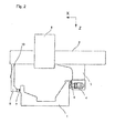
-
- Figur 1
- ist eine Seitensicht einer Fahrportalmaschine
- Figur 2
- ist eine weitere von der linken Seite in
Figur 1 betrachtete Seitenansicht der Fahrportalmaschine gemäß der vorliegenden Ausführungsform - Die in den
Figuren 1 und2 dargestellte Fahrportalmaschine weist einen Grundkörper 1 sowie ein Portal (Führungselement) 2. Das Portal 2 ist über eine erste Führungsschiene 5 und eine zweite Führungsschiene 7 mit dem Grundkörper in Kontakt, und somit entlang des Grundkörpers 1 verfahrbar (Y-Riehtung). - Am Portal 2 ist ein Schlitten 8 mit einer Bearbeitungseinheit 9 angebracht, der entlang des Portals 2 verfahrbar ist (X-Richtung). Die Bearbeitungseinheit 9 ist mit einem Bearbeitungswerkzeug (beispielsweise einem Fräser, einer Säge oder ähnlichem) versehen, um ein an der Basis 1 aufgespanntes Werkstück W zu bearbeiten.
- Die Führung des Portals 2 entlang dem Grundkörper 1 wird über einen ersten Träger 6, der mit der ersten Führungsschiene 7 in Verbindung steht, und einem zweiten Träger 3, der mit der zweiten Führungsschiene 5 in Verbindung steht, sichergestellt. Am zweiten Träger 3 ist ein Antrieb 4 (Masterantrieb) vorgesehen, der die Verfahrbarkeit des Portals 2 gegenüber dem Grundkörper 1 bereitstellt. Am ersten Träger 6 hingegen ist kein weiterer Antrieb (Slaveantrieb) vorgesehen. Dies bedeutet, dass die vorliegende Fahrportalmaschine eine sogenannte einseitig angetriebene Fahrportalmaschine ist.
- Am ersten Träger 6, der keinen eigenen Antrieb aufweist, ist ein Beschleunigungssensor 10 angebracht. Dieser Beschleunigungssensor 10 dient zur Messung der Schwingungsbewegung bzw. der Deflektion am Träger 6. Der Beschleunigungssensor kann jedoch auch am Portal 2, am ersten Träger 6 oder am zweiten Träger 3 angebracht sein.
- Der Beschleunigungssensor 10 ist Teil eines Regelsystems, das auf Grundlage des Erfassungsergebnisses des Beschleunigungssensors 10 die Bewegung des Antriebs 4 beeinflusst. Durch diese Einwirkung kann eine aktive Dämpfung kritischer Eigenfrequenzen der verfahrbaren Komponenten der Bearbeitungsmaschine erreicht werden. Insbesondere wird durch die gezielte Ansteuerung der Bewegung am Motor dem Gesamtsystem Schwingungsenergie entzogen.
Claims (12)
- Bearbeitungsmaschine zur Bearbeitung von Werkstücken, mit:einem Grundkörper (1), einem entlang des Grundkörpers (1) bewegbaren Führungselements (2, 3, 6), und einer am Führungselement (2, 3, 6) angebrachten Bearbeitungseinheit (9), wobeidas Führungselement (2) mit einem Antrieb (4), der an einer Lagerung des Führungselements (2, 3, 6) am Grundkörper (1) vorgesehen ist, relativ gegenüber dem Grundkörper (1) angetrieben wird, und ferner zumindest ein Sensor (10) am Führungselement (2, 3, 6) angebracht ist,eine Steuereinrichtung auf Grundlage des Erfassungsergebnisses des Sensors eine Antriebsgröße des Antriebs (4) steuert,und die Bearbeitungseinheit (9) zumindest abschnittsweise zwischen dem Sensor (10) und dem Antrieb (4) am Führungselement (2, 3, 6) angebracht ist.
- Bearbeitungsmaschine gemäß Anspruch 1, bei der das Führungselement über einen ersten Träger (6) und einen zweiten Träger (3) über Führungsschienen (5, 7) mit dem Grundkörper (1) in Kontakt steht.
- Bearbeitungsmaschine gemäß Anspruch 2, bei der die Führungsschienen eine erste Führungsschiene (7) und eine zweite Führungsschiene (5) aufweisen, die an entgegengesetzten Seiten des Grundkörpers (1) angebracht sind.
- Bearbeitungsmaschine gemäß einem der vorangegangenen Ansprüche, bei der die Bearbeitungseinheit (9) über einen entlang des Führungselements (2, 3, 6) bewegbaren Schlitten (8) am Führungselement (2, 3, 6) angebracht ist.
- Bearbeitungsmaschine gemäß einem der vorangegangenen Ansprüche, dadurch gekennzeichnet, dass der Beschleunigungssensor (10) an einem Abschnitt des Führungselements (2, 3, 6) angebracht ist, der an einem vom Antrieb (4) entfernt gelegenen Ende befindlich ist.
- Bearbeitungsmaschine gemäß einem der vorangegangenen Ansprüche, dadurch gekennzeichnet, dass die Bearbeitungsmaschine eine Fahrportalmaschine mit einem einseitig angetriebenen Fahrportal ist.
- Bearbeitungsmaschine gemäß einem der vorangegangenen Ansprüche, dadurch gekennzeichnet, dass der Sensor (10) ein Beschleunigungssensor, ein Laser-Vibrometer, ein Linearmesssystem zur Erfassung einer Linearbewegung des Führungselements (2, 3, 6) oder ein Geschwindigkeitssensor ist.
- Bearbeitungsmaschine gemäß Anspruch 7, dadurch gekennzeichnet, dass das Linearmesssystem ein rotatorisches Linearmesssystem ist, das über ein Messrad eine Linearbewegung am Maschinengestell erfasst.
- Bearbeitungsmaschine gemäß einem der vorangegangenen Ansprüche, dadurch gekennzeichnet, dass die Bearbeitungsmaschine eine Linearportalmaschine, eine Auslegermaschine, ein Roboter, eine Stabkinematikmaschine, ein Aggregat für eine Durchlaufmaschine oder ein Handhabungsgerät ist.
- Bearbeitungsmaschine gemäß einem der vorangegangenen Ansprüche, dadurch gekennzeichnet, dass die Bearbeitungseinheit (9) abschnittsweise in einem Bereich zwischen dem Sensor (10) und dem Antrieb (4) entlang des Führungselements verfahrbar ist.
- Bearbeitungsmaschine gemäß einem der vorangegangenen Ansprüche, dadurch gekennzeichnet, dass zumindest zwei Sensoren am Führungselement (2, 3, 6) angebracht sind, und die Steuereinheit das Erfassungsergebnis der Sensoren abgleicht und ggf. interpoliert.
- Verfahren zur Bereitstellung eines geregelten Antriebs für eine Bearbeitungsmaschine gemäß einem der vorangegangenen Ansprüche, mit den Schritten:Durchführen einer FEM-Analyse zur Bestimmung von zumindest der ersten Eigenfrequenz und Eigenform eines Führungselements,Platzieren eines Sensors, insbesondere Beschleunigungssensors, an einem Abschnitt des Führungselements auf Grundlage der ermittelten Eigenform,Steuern einer Antriebsgröße des Antriebs (4) der Bearbeitungsmaschine auf Grundlage des Erfassungsergebnisses des Sensors.
Priority Applications (1)
| Application Number | Priority Date | Filing Date | Title |
|---|---|---|---|
| PL13165088T PL2656966T3 (pl) | 2012-04-27 | 2013-04-24 | Obrabiarka z układem tłumienia drgań |
Applications Claiming Priority (1)
| Application Number | Priority Date | Filing Date | Title |
|---|---|---|---|
| DE102012207110A DE102012207110A1 (de) | 2012-04-27 | 2012-04-27 | Schwingungsdämpfungssystem |
Publications (2)
| Publication Number | Publication Date |
|---|---|
| EP2656966A1 true EP2656966A1 (de) | 2013-10-30 |
| EP2656966B1 EP2656966B1 (de) | 2019-12-25 |
Family
ID=48182780
Family Applications (1)
| Application Number | Title | Priority Date | Filing Date |
|---|---|---|---|
| EP13165088.9A Active EP2656966B1 (de) | 2012-04-27 | 2013-04-24 | Bearbeitungsmaschine mit Schwingungsdämpfungssystem |
Country Status (4)
| Country | Link |
|---|---|
| EP (1) | EP2656966B1 (de) |
| CN (1) | CN203636510U (de) |
| DE (1) | DE102012207110A1 (de) |
| PL (1) | PL2656966T3 (de) |
Families Citing this family (1)
| Publication number | Priority date | Publication date | Assignee | Title |
|---|---|---|---|---|
| DE102017210959A1 (de) * | 2017-06-28 | 2019-01-03 | Trumpf Werkzeugmaschinen Gmbh + Co. Kg | Werkzeugmaschine mit einer Mehrzahl von Sensoren |
Citations (5)
| Publication number | Priority date | Publication date | Assignee | Title |
|---|---|---|---|---|
| US4810941A (en) * | 1986-04-17 | 1989-03-07 | Canon Kabushiki Kaisha | Control system for a servomotor |
| US5432423A (en) * | 1993-04-29 | 1995-07-11 | Universal Instruments Corporation | Electronic damping system |
| DE10246093C1 (de) | 2002-10-02 | 2003-11-27 | Siemens Ag | Verfahren zur Dämpfung mechanischer Schwingungen von Achsen von Werkzeugmaschinen, Produktionsmaschinen oder Robotern |
| EP1810776A1 (de) * | 2006-01-24 | 2007-07-25 | ASM Technology Singapore Pte Ltd. | Gantrypositionierungssystem |
| DE102009008900A1 (de) * | 2008-05-07 | 2009-11-12 | Etel S.A. | Einrichtung zum Regeln eines Portalrahmens mit zweifachem Antriebsmittel |
Family Cites Families (5)
| Publication number | Priority date | Publication date | Assignee | Title |
|---|---|---|---|---|
| GB9815830D0 (en) * | 1998-07-22 | 1998-09-16 | Renishaw Plc | Method of and apparatus for reducing vibrations on probes carried by coordinate measuring machines |
| DE10144459A1 (de) * | 2001-09-10 | 2003-04-03 | Werner Kluft | Überwachung von Werkzeugmaschinen-Komponenten mit einem Überwachungssystem |
| DE10247354A1 (de) * | 2002-10-10 | 2004-04-29 | P&L Gmbh Co. Kg. | Aktive Schwingungsdämpfung in einer Werkzeugmaschine |
| DE102005044048B4 (de) * | 2004-09-30 | 2007-05-03 | Unaxis International Trading Ltd. | Wire Bonder |
| CH702248A1 (de) * | 2009-11-19 | 2011-05-31 | Josef Vogel | Oberflächenbearbeitungsvorrichtung. |
-
2012
- 2012-04-27 DE DE102012207110A patent/DE102012207110A1/de not_active Ceased
-
2013
- 2013-04-24 PL PL13165088T patent/PL2656966T3/pl unknown
- 2013-04-24 EP EP13165088.9A patent/EP2656966B1/de active Active
- 2013-04-27 CN CN201320224922.1U patent/CN203636510U/zh not_active Expired - Fee Related
Patent Citations (5)
| Publication number | Priority date | Publication date | Assignee | Title |
|---|---|---|---|---|
| US4810941A (en) * | 1986-04-17 | 1989-03-07 | Canon Kabushiki Kaisha | Control system for a servomotor |
| US5432423A (en) * | 1993-04-29 | 1995-07-11 | Universal Instruments Corporation | Electronic damping system |
| DE10246093C1 (de) | 2002-10-02 | 2003-11-27 | Siemens Ag | Verfahren zur Dämpfung mechanischer Schwingungen von Achsen von Werkzeugmaschinen, Produktionsmaschinen oder Robotern |
| EP1810776A1 (de) * | 2006-01-24 | 2007-07-25 | ASM Technology Singapore Pte Ltd. | Gantrypositionierungssystem |
| DE102009008900A1 (de) * | 2008-05-07 | 2009-11-12 | Etel S.A. | Einrichtung zum Regeln eines Portalrahmens mit zweifachem Antriebsmittel |
Also Published As
| Publication number | Publication date |
|---|---|
| DE102012207110A1 (de) | 2013-10-31 |
| EP2656966B1 (de) | 2019-12-25 |
| PL2656966T3 (pl) | 2020-05-18 |
| CN203636510U (zh) | 2014-06-11 |
Similar Documents
| Publication | Publication Date | Title |
|---|---|---|
| DE4495551C2 (de) | Z-Achsen-Antrieb für eine Werkzeugmaschine | |
| DE19960834B4 (de) | Verfahren und Vorrichtung zur Störungserfassung, insbesondere zur Kollisionserfassung, im Antriebssystem einer numerisch gesteuerten Werkzeugmaschine | |
| DE102011018237A9 (de) | Fördereinrichtung für Automatisierungsstraßen | |
| WO2020229598A1 (de) | Transportsystem sowie transportverfahren | |
| DE102006049867B4 (de) | Werkzeugmaschine und Verfahren zur Unterdrückung von Ratterschwingungen | |
| DE102017009636B4 (de) | Koordinatenmessvorrichtung | |
| DE102007019453B4 (de) | Koordinatenmessgerät mit zwei Schlitten auf gemeinsamer Führung | |
| EP1166953B1 (de) | Werkzeugmaschine mit einem Führungssystem für eine Koordinatenfahrwerk | |
| EP3574379B1 (de) | Verfahren zum betreiben einer werkstückbearbeitungsanlage, sowie werkstückbearbeitungsanlage | |
| DE3627706C2 (de) | ||
| EP2656966B1 (de) | Bearbeitungsmaschine mit Schwingungsdämpfungssystem | |
| DE102009039203A1 (de) | Einrichtung zur Kompensation von Drehmomenten, die durch Beschleunigung von redundanten Zusatzachsen bei Mess- und Werkzeugmaschinen entstehen mittels einer Mehrzahl von koordiniert linear bewegbarer Ausgleichsmassen | |
| EP1287946A1 (de) | Werkzeugmaschine mit einer mittels Linearmotoren angetriebenen Funktionseinheit | |
| EP3596563B1 (de) | Verfahren zum bearbeiten von werkstücken mit einem bearbeitungszentrum | |
| DE102007021294B4 (de) | Dynamisch optimierte Werkzeugmaschine mit überlagerten Antriebssystemen | |
| DE19933234A1 (de) | Linearantriebseinrichtung, insbesondere für eine Bestückungsmaschine, und Bestückungsmaschine | |
| DE69905664T2 (de) | Steuervorrichtung und Verfahren zum Steuern eines Linearantriebes | |
| WO2005123339A2 (de) | Schleifmaschine nach art einer universal-rund-/unrundschleifmaschine | |
| DE19637632A1 (de) | Numerisches Bahn-Steuersystem | |
| DE102004043055B4 (de) | Führungsvorrichtung zur Führung eines bewegbaren Maschinenelementes einer Maschine | |
| DE202010004242U1 (de) | Vorrichtung zum Schneiden, Werkzeugmaschine | |
| WO2022263151A1 (de) | Planar-positioniervorrichtung und arbeitstisch | |
| DE10159482A1 (de) | Vorrichtung und Verfahren zur Positionierung von Füge- oder Bearbeitungseinheiten | |
| DE102024104391B3 (de) | Laserbearbeitungsmaschine | |
| DE102011016304B4 (de) | Vorrichtung für einen Mehrkoordinatenantrieb |
Legal Events
| Date | Code | Title | Description |
|---|---|---|---|
| PUAI | Public reference made under article 153(3) epc to a published international application that has entered the european phase |
Free format text: ORIGINAL CODE: 0009012 |
|
| AK | Designated contracting states |
Kind code of ref document: A1 Designated state(s): AL AT BE BG CH CY CZ DE DK EE ES FI FR GB GR HR HU IE IS IT LI LT LU LV MC MK MT NL NO PL PT RO RS SE SI SK SM TR |
|
| AX | Request for extension of the european patent |
Extension state: BA ME |
|
| 17P | Request for examination filed |
Effective date: 20131128 |
|
| RBV | Designated contracting states (corrected) |
Designated state(s): AL AT BE BG CH CY CZ DE DK EE ES FI FR GB GR HR HU IE IS IT LI LT LU LV MC MK MT NL NO PL PT RO RS SE SI SK SM TR |
|
| 17Q | First examination report despatched |
Effective date: 20140604 |
|
| APBK | Appeal reference recorded |
Free format text: ORIGINAL CODE: EPIDOSNREFNE |
|
| APBN | Date of receipt of notice of appeal recorded |
Free format text: ORIGINAL CODE: EPIDOSNNOA2E |
|
| APBR | Date of receipt of statement of grounds of appeal recorded |
Free format text: ORIGINAL CODE: EPIDOSNNOA3E |
|
| APAF | Appeal reference modified |
Free format text: ORIGINAL CODE: EPIDOSCREFNE |
|
| RAP1 | Party data changed (applicant data changed or rights of an application transferred) |
Owner name: HOMAG GMBH |
|
| APBT | Appeal procedure closed |
Free format text: ORIGINAL CODE: EPIDOSNNOA9E |
|
| GRAP | Despatch of communication of intention to grant a patent |
Free format text: ORIGINAL CODE: EPIDOSNIGR1 |
|
| STAA | Information on the status of an ep patent application or granted ep patent |
Free format text: STATUS: GRANT OF PATENT IS INTENDED |
|
| INTG | Intention to grant announced |
Effective date: 20190918 |
|
| GRAS | Grant fee paid |
Free format text: ORIGINAL CODE: EPIDOSNIGR3 |
|
| GRAA | (expected) grant |
Free format text: ORIGINAL CODE: 0009210 |
|
| STAA | Information on the status of an ep patent application or granted ep patent |
Free format text: STATUS: THE PATENT HAS BEEN GRANTED |
|
| AK | Designated contracting states |
Kind code of ref document: B1 Designated state(s): AL AT BE BG CH CY CZ DE DK EE ES FI FR GB GR HR HU IE IS IT LI LT LU LV MC MK MT NL NO PL PT RO RS SE SI SK SM TR |
|
| REG | Reference to a national code |
Ref country code: GB Ref legal event code: FG4D Free format text: NOT ENGLISH |
|
| REG | Reference to a national code |
Ref country code: CH Ref legal event code: EP |
|
| REG | Reference to a national code |
Ref country code: AT Ref legal event code: REF Ref document number: 1216636 Country of ref document: AT Kind code of ref document: T Effective date: 20200115 |
|
| REG | Reference to a national code |
Ref country code: DE Ref legal event code: R096 Ref document number: 502013014099 Country of ref document: DE |
|
| REG | Reference to a national code |
Ref country code: IE Ref legal event code: FG4D Free format text: LANGUAGE OF EP DOCUMENT: GERMAN |
|
| REG | Reference to a national code |
Ref country code: NL Ref legal event code: MP Effective date: 20191225 |
|
| PG25 | Lapsed in a contracting state [announced via postgrant information from national office to epo] |
Ref country code: LT Free format text: LAPSE BECAUSE OF FAILURE TO SUBMIT A TRANSLATION OF THE DESCRIPTION OR TO PAY THE FEE WITHIN THE PRESCRIBED TIME-LIMIT Effective date: 20191225 Ref country code: GR Free format text: LAPSE BECAUSE OF FAILURE TO SUBMIT A TRANSLATION OF THE DESCRIPTION OR TO PAY THE FEE WITHIN THE PRESCRIBED TIME-LIMIT Effective date: 20200326 Ref country code: BG Free format text: LAPSE BECAUSE OF FAILURE TO SUBMIT A TRANSLATION OF THE DESCRIPTION OR TO PAY THE FEE WITHIN THE PRESCRIBED TIME-LIMIT Effective date: 20200325 Ref country code: FI Free format text: LAPSE BECAUSE OF FAILURE TO SUBMIT A TRANSLATION OF THE DESCRIPTION OR TO PAY THE FEE WITHIN THE PRESCRIBED TIME-LIMIT Effective date: 20191225 Ref country code: NO Free format text: LAPSE BECAUSE OF FAILURE TO SUBMIT A TRANSLATION OF THE DESCRIPTION OR TO PAY THE FEE WITHIN THE PRESCRIBED TIME-LIMIT Effective date: 20200325 Ref country code: LV Free format text: LAPSE BECAUSE OF FAILURE TO SUBMIT A TRANSLATION OF THE DESCRIPTION OR TO PAY THE FEE WITHIN THE PRESCRIBED TIME-LIMIT Effective date: 20191225 Ref country code: SE Free format text: LAPSE BECAUSE OF FAILURE TO SUBMIT A TRANSLATION OF THE DESCRIPTION OR TO PAY THE FEE WITHIN THE PRESCRIBED TIME-LIMIT Effective date: 20191225 |
|
| REG | Reference to a national code |
Ref country code: LT Ref legal event code: MG4D |
|
| PG25 | Lapsed in a contracting state [announced via postgrant information from national office to epo] |
Ref country code: RS Free format text: LAPSE BECAUSE OF FAILURE TO SUBMIT A TRANSLATION OF THE DESCRIPTION OR TO PAY THE FEE WITHIN THE PRESCRIBED TIME-LIMIT Effective date: 20191225 Ref country code: HR Free format text: LAPSE BECAUSE OF FAILURE TO SUBMIT A TRANSLATION OF THE DESCRIPTION OR TO PAY THE FEE WITHIN THE PRESCRIBED TIME-LIMIT Effective date: 20191225 |
|
| PG25 | Lapsed in a contracting state [announced via postgrant information from national office to epo] |
Ref country code: AL Free format text: LAPSE BECAUSE OF FAILURE TO SUBMIT A TRANSLATION OF THE DESCRIPTION OR TO PAY THE FEE WITHIN THE PRESCRIBED TIME-LIMIT Effective date: 20191225 |
|
| PG25 | Lapsed in a contracting state [announced via postgrant information from national office to epo] |
Ref country code: EE Free format text: LAPSE BECAUSE OF FAILURE TO SUBMIT A TRANSLATION OF THE DESCRIPTION OR TO PAY THE FEE WITHIN THE PRESCRIBED TIME-LIMIT Effective date: 20191225 Ref country code: PT Free format text: LAPSE BECAUSE OF FAILURE TO SUBMIT A TRANSLATION OF THE DESCRIPTION OR TO PAY THE FEE WITHIN THE PRESCRIBED TIME-LIMIT Effective date: 20200520 Ref country code: RO Free format text: LAPSE BECAUSE OF FAILURE TO SUBMIT A TRANSLATION OF THE DESCRIPTION OR TO PAY THE FEE WITHIN THE PRESCRIBED TIME-LIMIT Effective date: 20191225 Ref country code: NL Free format text: LAPSE BECAUSE OF FAILURE TO SUBMIT A TRANSLATION OF THE DESCRIPTION OR TO PAY THE FEE WITHIN THE PRESCRIBED TIME-LIMIT Effective date: 20191225 Ref country code: CZ Free format text: LAPSE BECAUSE OF FAILURE TO SUBMIT A TRANSLATION OF THE DESCRIPTION OR TO PAY THE FEE WITHIN THE PRESCRIBED TIME-LIMIT Effective date: 20191225 |
|
| PG25 | Lapsed in a contracting state [announced via postgrant information from national office to epo] |
Ref country code: SK Free format text: LAPSE BECAUSE OF FAILURE TO SUBMIT A TRANSLATION OF THE DESCRIPTION OR TO PAY THE FEE WITHIN THE PRESCRIBED TIME-LIMIT Effective date: 20191225 Ref country code: SM Free format text: LAPSE BECAUSE OF FAILURE TO SUBMIT A TRANSLATION OF THE DESCRIPTION OR TO PAY THE FEE WITHIN THE PRESCRIBED TIME-LIMIT Effective date: 20191225 Ref country code: IS Free format text: LAPSE BECAUSE OF FAILURE TO SUBMIT A TRANSLATION OF THE DESCRIPTION OR TO PAY THE FEE WITHIN THE PRESCRIBED TIME-LIMIT Effective date: 20200425 |
|
| REG | Reference to a national code |
Ref country code: DE Ref legal event code: R097 Ref document number: 502013014099 Country of ref document: DE |
|
| PG25 | Lapsed in a contracting state [announced via postgrant information from national office to epo] |
Ref country code: ES Free format text: LAPSE BECAUSE OF FAILURE TO SUBMIT A TRANSLATION OF THE DESCRIPTION OR TO PAY THE FEE WITHIN THE PRESCRIBED TIME-LIMIT Effective date: 20191225 Ref country code: DK Free format text: LAPSE BECAUSE OF FAILURE TO SUBMIT A TRANSLATION OF THE DESCRIPTION OR TO PAY THE FEE WITHIN THE PRESCRIBED TIME-LIMIT Effective date: 20191225 |
|
| PLBE | No opposition filed within time limit |
Free format text: ORIGINAL CODE: 0009261 |
|
| STAA | Information on the status of an ep patent application or granted ep patent |
Free format text: STATUS: NO OPPOSITION FILED WITHIN TIME LIMIT |
|
| PG25 | Lapsed in a contracting state [announced via postgrant information from national office to epo] |
Ref country code: MC Free format text: LAPSE BECAUSE OF FAILURE TO SUBMIT A TRANSLATION OF THE DESCRIPTION OR TO PAY THE FEE WITHIN THE PRESCRIBED TIME-LIMIT Effective date: 20191225 Ref country code: SI Free format text: LAPSE BECAUSE OF FAILURE TO SUBMIT A TRANSLATION OF THE DESCRIPTION OR TO PAY THE FEE WITHIN THE PRESCRIBED TIME-LIMIT Effective date: 20191225 |
|
| REG | Reference to a national code |
Ref country code: CH Ref legal event code: PL |
|
| 26N | No opposition filed |
Effective date: 20200928 |
|
| PG25 | Lapsed in a contracting state [announced via postgrant information from national office to epo] |
Ref country code: FR Free format text: LAPSE BECAUSE OF NON-PAYMENT OF DUE FEES Effective date: 20200430 Ref country code: LU Free format text: LAPSE BECAUSE OF NON-PAYMENT OF DUE FEES Effective date: 20200424 Ref country code: LI Free format text: LAPSE BECAUSE OF NON-PAYMENT OF DUE FEES Effective date: 20200430 Ref country code: CH Free format text: LAPSE BECAUSE OF NON-PAYMENT OF DUE FEES Effective date: 20200430 |
|
| REG | Reference to a national code |
Ref country code: BE Ref legal event code: MM Effective date: 20200430 |
|
| PG25 | Lapsed in a contracting state [announced via postgrant information from national office to epo] |
Ref country code: BE Free format text: LAPSE BECAUSE OF NON-PAYMENT OF DUE FEES Effective date: 20200430 |
|
| GBPC | Gb: european patent ceased through non-payment of renewal fee |
Effective date: 20200424 |
|
| PG25 | Lapsed in a contracting state [announced via postgrant information from national office to epo] |
Ref country code: IE Free format text: LAPSE BECAUSE OF NON-PAYMENT OF DUE FEES Effective date: 20200424 Ref country code: GB Free format text: LAPSE BECAUSE OF NON-PAYMENT OF DUE FEES Effective date: 20200424 |
|
| PG25 | Lapsed in a contracting state [announced via postgrant information from national office to epo] |
Ref country code: TR Free format text: LAPSE BECAUSE OF FAILURE TO SUBMIT A TRANSLATION OF THE DESCRIPTION OR TO PAY THE FEE WITHIN THE PRESCRIBED TIME-LIMIT Effective date: 20191225 Ref country code: MT Free format text: LAPSE BECAUSE OF FAILURE TO SUBMIT A TRANSLATION OF THE DESCRIPTION OR TO PAY THE FEE WITHIN THE PRESCRIBED TIME-LIMIT Effective date: 20191225 Ref country code: CY Free format text: LAPSE BECAUSE OF FAILURE TO SUBMIT A TRANSLATION OF THE DESCRIPTION OR TO PAY THE FEE WITHIN THE PRESCRIBED TIME-LIMIT Effective date: 20191225 |
|
| PG25 | Lapsed in a contracting state [announced via postgrant information from national office to epo] |
Ref country code: MK Free format text: LAPSE BECAUSE OF FAILURE TO SUBMIT A TRANSLATION OF THE DESCRIPTION OR TO PAY THE FEE WITHIN THE PRESCRIBED TIME-LIMIT Effective date: 20191225 |
|
| P01 | Opt-out of the competence of the unified patent court (upc) registered |
Effective date: 20230529 |
|
| PGFP | Annual fee paid to national office [announced via postgrant information from national office to epo] |
Ref country code: PL Payment date: 20230414 Year of fee payment: 11 |
|
| PGFP | Annual fee paid to national office [announced via postgrant information from national office to epo] |
Ref country code: AT Payment date: 20240419 Year of fee payment: 12 |
|
| PG25 | Lapsed in a contracting state [announced via postgrant information from national office to epo] |
Ref country code: PL Free format text: LAPSE BECAUSE OF NON-PAYMENT OF DUE FEES Effective date: 20240424 |
|
| PGFP | Annual fee paid to national office [announced via postgrant information from national office to epo] |
Ref country code: DE Payment date: 20250423 Year of fee payment: 13 |
|
| PGFP | Annual fee paid to national office [announced via postgrant information from national office to epo] |
Ref country code: IT Payment date: 20250428 Year of fee payment: 13 |
|
| REG | Reference to a national code |
Ref country code: AT Ref legal event code: MM01 Ref document number: 1216636 Country of ref document: AT Kind code of ref document: T Effective date: 20250424 |
|
| PG25 | Lapsed in a contracting state [announced via postgrant information from national office to epo] |
Ref country code: AT Free format text: LAPSE BECAUSE OF NON-PAYMENT OF DUE FEES Effective date: 20250424 |