EP2656820A1 - Vorrichtung zum Stabilisieren von Körpersegmenten - Google Patents
Vorrichtung zum Stabilisieren von Körpersegmenten Download PDFInfo
- Publication number
- EP2656820A1 EP2656820A1 EP20130166013 EP13166013A EP2656820A1 EP 2656820 A1 EP2656820 A1 EP 2656820A1 EP 20130166013 EP20130166013 EP 20130166013 EP 13166013 A EP13166013 A EP 13166013A EP 2656820 A1 EP2656820 A1 EP 2656820A1
- Authority
- EP
- European Patent Office
- Prior art keywords
- body segments
- textile
- layer
- stabilizing
- plastic
- Prior art date
- Legal status (The legal status is an assumption and is not a legal conclusion. Google has not performed a legal analysis and makes no representation as to the accuracy of the status listed.)
- Granted
Links
- 230000000087 stabilizing effect Effects 0.000 title claims description 12
- 239000004753 textile Substances 0.000 claims abstract description 20
- 229920003023 plastic Polymers 0.000 claims abstract description 16
- 239000004744 fabric Substances 0.000 claims abstract description 7
- 210000003141 lower extremity Anatomy 0.000 claims abstract description 3
- 210000001364 upper extremity Anatomy 0.000 claims abstract description 3
- 239000002184 metal Substances 0.000 claims description 4
- 239000002759 woven fabric Substances 0.000 claims 1
- 239000010410 layer Substances 0.000 description 19
- 239000003814 drug Substances 0.000 description 3
- 210000003423 ankle Anatomy 0.000 description 2
- 210000001503 joint Anatomy 0.000 description 2
- 210000000629 knee joint Anatomy 0.000 description 2
- 239000011505 plaster Substances 0.000 description 2
- 230000006641 stabilisation Effects 0.000 description 2
- 238000011105 stabilization Methods 0.000 description 2
- 208000007623 Lordosis Diseases 0.000 description 1
- 210000000746 body region Anatomy 0.000 description 1
- 210000000988 bone and bone Anatomy 0.000 description 1
- 230000000694 effects Effects 0.000 description 1
- 229920001971 elastomer Polymers 0.000 description 1
- 210000002758 humerus Anatomy 0.000 description 1
- 210000002414 leg Anatomy 0.000 description 1
- 238000004519 manufacturing process Methods 0.000 description 1
- 239000000463 material Substances 0.000 description 1
- 230000000399 orthopedic effect Effects 0.000 description 1
- 229920001084 poly(chloroprene) Polymers 0.000 description 1
- 229920001296 polysiloxane Polymers 0.000 description 1
- 238000007493 shaping process Methods 0.000 description 1
- 210000000323 shoulder joint Anatomy 0.000 description 1
- 239000002356 single layer Substances 0.000 description 1
- 239000007921 spray Substances 0.000 description 1
- 230000008961 swelling Effects 0.000 description 1
- 210000000689 upper leg Anatomy 0.000 description 1
Images
Classifications
-
- A—HUMAN NECESSITIES
- A61—MEDICAL OR VETERINARY SCIENCE; HYGIENE
- A61F—FILTERS IMPLANTABLE INTO BLOOD VESSELS; PROSTHESES; DEVICES PROVIDING PATENCY TO, OR PREVENTING COLLAPSING OF, TUBULAR STRUCTURES OF THE BODY, e.g. STENTS; ORTHOPAEDIC, NURSING OR CONTRACEPTIVE DEVICES; FOMENTATION; TREATMENT OR PROTECTION OF EYES OR EARS; BANDAGES, DRESSINGS OR ABSORBENT PADS; FIRST-AID KITS
- A61F5/00—Orthopaedic methods or devices for non-surgical treatment of bones or joints; Nursing devices ; Anti-rape devices
- A61F5/01—Orthopaedic devices, e.g. long-term immobilising or pressure directing devices for treating broken or deformed bones such as splints, casts or braces
- A61F5/0102—Orthopaedic devices, e.g. long-term immobilising or pressure directing devices for treating broken or deformed bones such as splints, casts or braces specially adapted for correcting deformities of the limbs or for supporting them; Ortheses, e.g. with articulations
- A61F5/0104—Orthopaedic devices, e.g. long-term immobilising or pressure directing devices for treating broken or deformed bones such as splints, casts or braces specially adapted for correcting deformities of the limbs or for supporting them; Ortheses, e.g. with articulations without articulation
- A61F5/0111—Orthopaedic devices, e.g. long-term immobilising or pressure directing devices for treating broken or deformed bones such as splints, casts or braces specially adapted for correcting deformities of the limbs or for supporting them; Ortheses, e.g. with articulations without articulation for the feet or ankles
-
- A—HUMAN NECESSITIES
- A61—MEDICAL OR VETERINARY SCIENCE; HYGIENE
- A61F—FILTERS IMPLANTABLE INTO BLOOD VESSELS; PROSTHESES; DEVICES PROVIDING PATENCY TO, OR PREVENTING COLLAPSING OF, TUBULAR STRUCTURES OF THE BODY, e.g. STENTS; ORTHOPAEDIC, NURSING OR CONTRACEPTIVE DEVICES; FOMENTATION; TREATMENT OR PROTECTION OF EYES OR EARS; BANDAGES, DRESSINGS OR ABSORBENT PADS; FIRST-AID KITS
- A61F13/00—Bandages or dressings; Absorbent pads
- A61F13/04—Plaster of Paris bandages; Other stiffening bandages
Definitions
- the invention relates to a device for stabilizing body segments:
- a sports sock having a toe-to-heel insert comprising a stirrup-type device in the form of two interconnected strips of suitable material joined together to stabilize the ankle and arranged horizontally perpendicular to the strips revolving band, which serves to restrict movement of the Talocalcaneonavikulargelenks and stabilize the ankle.
- the insert is connected to the sports stocking, among other things by spray bonding with plastic. It can also be provided on the two strips, a plastic layer.
- the "taping" ie the stabilization with tape tape can be omitted.
- plaster casts for fixing body segments are known which are used extensively in the field of medicine, in particular fractures of bone. However, these must be created individually, which is expensive.
- plastic shawl bandages are also known, which are likewise used in the field of medicine and, given their lower weight, are increasingly preferred to plaster casts.
- the object of the invention is to provide a novel device for stabilizing body segments, in particular for use in the field of sports and rehabilitation medicine, which can be marketed as a ready-made ready-made or as semi-finished customization.
- This object is achieved in that is applied to a textile carrier layer, which has the shape of the body segment to be stabilized, this stabilizing in its shape plastic layer.
- a functional anatomically congruent orthopedic aid fitting against the respective body segments is created. While in currently available on the market bandages a natural concave body overvoltage (for example in the lumbar lordosis) is caused, so that there must be used to apply pressure a pad, the device of the invention follows in all areas, even with concave body overvoltages of the body contour, creating a better Fit is achieved, and an undesirable pressure on body areas by pads or the like is avoided. Rather, it can be adjusted individually, where pressure is to be exerted on the body and where not.
- a device for stabilizing body segments which can be referred to as orthosis bandage or bandage orthosis and has a low weight high wearing comfort, since the textile support layer faces the skin of the user.
- movements of the various joints can be wholly or partially restricted, stabilized or supported, which can also be used to increase the natural biodynamics.
- the stabilizing plastic layer may be reticulate or planar, flexible or rigid, elastic, hard or soft, two- or three-dimensional, it also being possible to combine several of these properties in one device, for example by the specific use of different plastic layers for different areas the device, for example, a specific joint supporting and another only partially supporting.
- the plastic layer may be formed one or more layers.
- the plastic layer is immovably positioned due to its connection to the textile support layer. It can be sprayed on both outside and inside of the textile carrier fabric and covered with a slip-aid. It is of course possible to additionally soft plastic applications, for example made of silicone, as a pad (pressure pad) to be placed on the device to selectively exert pressure on certain body regions.
- the body segments are the upper or lower limbs or the trunk.
- the textile carrier layer is a textile knit or a fabric.
- the textile carrier layer may also be elastic, for example as an elastic textile fabric or fabric or as textile rubber effect or combination thereof.
- textile-like structures such as neoprene come into question.
- a development of the invention is that the device is constructed in multiple layers.
- the device may be rigid, elastic or flexible.
- the device it is possible to form the device not only single-layer, but also multi-layered.
- An embodiment of the invention is that the device covers one or more adjacent to the respective body segment further body segments and the or the intervening joints with.
- the device not only the adjacent joint is covered by the device, but at least partially also adjacent to this joint further body segment.
- the upper body would be at least partially, the shoulder joint and a part of the humerus covered.
- At least one stabilizing band is provided for increasing the adhesion.
- Such a stabilizing band can be designed to be both statically fixed and elastically fixing or to combine these two properties.
- a development of the invention is that an insert, in particular made of metal or plastic, is surrounded by the plastic layer.
- Such an insert may, for example, consist of a bendable metal element, which makes it possible to adapt the then still moldable device after the actual manufacturing process individually shaping a body part. or a metal element having a shape adapted to a body part
- the device according to the invention has a textile carrier layer 1 adapted to the shape of the affected body segment (s), which may be a textile knit or a textile fabric.
- a textile carrier layer 1 adapted to the shape of the affected body segment (s), which may be a textile knit or a textile fabric.
- a plastic layer 2 stabilizing the textile carrier layer 1 in its shape is applied. It may be provided that in certain highly stressed areas or This layer structure is repeated over the entire device in a sandwich until the desired mechanical strength is achieved.
- the device may comprise an air-inflatable pressure chamber 3, which makes it possible to improve the fit of the device on the body segment concerned or slightly loosening the seat of the device on the body segment during wear by depressurizing.
- This pressure chamber 3 has a valve 4, via which the pressure chamber 3 can be filled or emptied.
- the illustrated device also has means 5 for restricting the angle of movement of the knee joint, which are formed as a joint 5 connected to both parts of the device between the thigh comprehensive and the lower leg part of the device having an adjustable maximum flexion angle.
- the fixing straps 6 can be mounted in the horizontal direction or in any other layer form.
Landscapes
- Health & Medical Sciences (AREA)
- Vascular Medicine (AREA)
- Engineering & Computer Science (AREA)
- Biomedical Technology (AREA)
- Heart & Thoracic Surgery (AREA)
- Life Sciences & Earth Sciences (AREA)
- Animal Behavior & Ethology (AREA)
- General Health & Medical Sciences (AREA)
- Public Health (AREA)
- Veterinary Medicine (AREA)
- Orthopedic Medicine & Surgery (AREA)
- Nursing (AREA)
- Orthopedics, Nursing, And Contraception (AREA)
Abstract
Description
- Die Erfindung betrifft eine Vorrichtung zum Stabilisieren von Körpersegmenten:
- Aus der
US 6,779,282 B2 ist ein Sportstrumpf mit einer sich von den Zehen bis zur Ferse erstreckenden Einlage bekannt, die eine steigbügelartige Vorrichtung in Form zweier miteinander verbundener Streifen aus geeignetem Material umfaßt, welche miteinander verbunden sind, um den Knöchel zu stabilisieren und die ein senkrecht zu den Streifen angeordnetes horizontal umlaufendes Band aufweist, das zu einer Bewegungsbeschränkung des Talocalcaneonavikulargelenks und Stabilisieren des Knöchels dient. Hierbei ist vorgesehen, daß die Einlage mit dem Sportstrumpf unter anderem durch Sprühbinden mit Kunststoff verbunden ist. Es kann auch eine Kunststoffschicht auf den beiden Streifen vorgesehen sein. Bei Verwendung dieser Vorrichtung kann das "Tapen", d.h. das Stabilisieren mit Tape-Band entfallen. - Es sind weiterhin Gipsverbände zum Festlegen von Körpersegmenten bekannt, welche weitgehend im Bereich der Medizin, insbesondere bei Knochenbrüchen, zur Anwendung kommen. Diese müssen jedoch individuell angelegt werden, was aufwendig ist.
- Es sind schließlich auch Kunststoffschalverbände bekannt, welche ebenfalls im Bereich der Medizin verwendet werden und in Anbetracht ihres geringeren Gewichtes den Gipsverbänden zunehmend bevorzugt werden.
- Aufgabe der Erfindung ist es, insbesondere für die Anwendung im Bereich des Sports und der Rehabilitationsmedizin eine neuartige Vorrichtung zum Stabilisieren von Körpersegmenten zu schaffen, die als vorgefertigte Konfektionsware oder auch als halbfertige Maßkonfektion vertrieben werden kann.
- Diese Aufgabe wird erfindungsgemäß dadurch gelöst, daß auf eine textile Trägerschicht, welche die Form des zu stabilisierenden Körpersegmentes aufweist, eine diese in ihrer Form stabilisierende Kunststoffschicht aufgetragen ist.
- Es wird im Rahmen der Erfindung ein funktionelles anatomisch kongruent an den jeweiligen Körpersegmenten anliegendes orthopädisches Hilfsmittel geschaffen. Während bei derzeit am Markt erhältlichen Bandagen eine natürliche konkave Körperüberspannung (beispielsweise im Bereich der Lendenlordose) hervorgerufen wird, so daß dort zur Druckausübung eine Pelotte eingesetzt werden muß, folgt die erfindungsgemäße Vorrichtung in allen Bereichen, auch bei konkaven Körperüberspannungen der Körperkontur, wodurch eine bessere Paßform erreicht wird, und ein unerwünschter Druck auf Körperbereiche durch Pelotten oder dergleichen vermieden wird. Vielmehr kann individuell eingestellt werden, wo Druck auf den Körper ausgeübt werden soll und wo nicht. Auf diese Weise wird eine Vorrichtung zum Stabilisieren von Körpersegmenten geschaffen, die als Orthesen-Bandage oder als Bandagen-Orthese bezeichnet werden kann und bei geringem Gewicht einen hohen Tragekomfort aufweist, da die textile Trägerschicht der Haut des Benutzers zugewandt ist. Mit dieser Vorrichtung können Bewegungen der verschiedenen Gelenke ganz oder teilweise eingeschränkt, stabilisiert oder unterstützt werden, was auch zur Erhöhung der natürlichen Biodynamik genutzt werden kann.
- Die stabilisierende Kunststoffschicht kann netzartig oder flächig, flexibel oder starr, elastisch, hart oder weich, zwei- oder dreidimensional sein, wobei es auch möglich ist, mehrere dieser Eigenschaften in einer Vorrichtung miteinander zu kombinieren, beispielsweise durch die gezielte Verwendung unterschiedlicher Kunststoffschichten für verschiedene Bereiche der Vorrichtung, beispielsweise ein bestimmtes Gelenk unterstützend und ein anderes nur teilunterstützend. Ebenso kann die Kunststoffschicht ein- oder mehrlagig ausgebildet sein. Die Kunststoffschicht ist aufgrund ihrer Verbindung mit der textilen Trägerschicht unverrückbar positioniert. Sie kann sowohl außen als auch innen am textilen Trägergewebe aufgespritzt sein und mit einer Rutschhilfe abgedeckt werden. Es ist selbstverständlich möglich, zusätzlich weiche Kunststoffapplikationen, beispielsweise aus Silikon, als Pelotte (Druckpolster) auf der Vorrichtung anzuordnen, um gezielt Druck auf bestimmte Körperregionen auszuüben.
- Erfindungsgemäß ist vorgesehen, daß die Körpersegmente die oberen oder unteren Gliedmaßen oder der Rumpf sind.
- Es liegt im Rahmen der Erfindung, daß die textile Trägerschicht ein textiles Gewirk oder ein Gewebe ist.
- Grundsätzlich kommen beide Alternativen in Frage. Die textile Trägerschicht kann auch elastisch ausgebildet sein, beispielsweise als elastisches Textilgewirk oder -gewebe oder als Textilgummigewirk oder Kombination derselben. Grundsätzlich kommen auch textilähnliche Strukturen, wie beispielsweise Neopren in Frage.
- Eine Weiterbildung der Erfindung besteht darin, daß die Vorrichtung mehrlagig aufgebaut ist.
- Die Vorrichtung kann starr, elastisch oder flexibel ausgebildet sein.
- Es ist möglich, die Vorrichtung nicht nur einlagig, sondern auch mehrlagig auszubilden.
- Eine Ausbildung der Erfindung besteht darin, daß die Vorrichtung ein oder mehrere an das jeweilige Körpersegment angrenzende weitere Körpersegmente und das bzw. die dazwischen liegenden Gelenke mit abdeckt.
- Es versteht sich, daß nicht nur das angrenzende Gelenk mit von der Vorrichtung abgedeckt wird, sondern mindestens teilweise auch das an dieses Gelenk angrenzende weitere Körpersegment. Bei einer Vorrichtung, die zur Stabilisierung des Oberkörpers und eines Arms vorgesehen ist, wäre somit der Oberkörper zumindest teilweise, das Schultergelenk und ein Teil des Oberarmknochens abgedeckt.
- In diesem Zusammenhang ist es möglich, daß Mittel zur Beschränkung des Bewegungswinkels des bzw. der Gelenke vorgesehen ist.
- Ebenfalls im Rahmen der Erfindung liegt es, daß mindestens ein Stabilisierungsband zum Erhöhen der Haftung vorgesehen ist.
- Ein solches Stabilisierungsband kann sowohl statisch fest als auch elastisch fixierend oder diese beiden Eigenschaften kombinierend ausgebildet sein.
- Eine Weiterbildung der Erfindung besteht darin, daß ein Einlegestück, insbesondere aus Metall oder aus Kunststoff, von der Kunststoffschicht umgeben ist.
- Ein solches Einlegestück kann beispielsweise aus einem biegbaren Metallelement bestehen, das es ermöglicht, die dann noch formbare Vorrichtung nach dem eigentlichen Herstellungsvorgang individuell formgebend einem Körperteil anzupassen. oder einem Metallelement mit einer einem Körperteil angepaßten Formgebung
- Ebenfalls ist es erfindungsgemäß vorgesehen, daß an der dem Körper des Benutzer zugewandten Innenseite eine über ein Ventil mit Luft befüllbare Druckkammer vorgesehen ist.
- Durch das Aufpumpen einer solchen Druckkammer kann das Anliegen der Vorrichtung am Körper noch verbessert werden, durch Luftablassen können Schwellungen kompensiert werden oder aber es kann Druck auf die stabilisierten Körpersegmente ausgeübt werden.
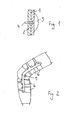
- Nachfolgend wird ein Ausführungsbeispiel der Erfindung anhand von Zeichnungen beschrieben.
- Es zeigt
- Fig. 1
- eine schematische Darstellung des Aufbaus der Vorrichtung,
- Fig. 2
- eine schematische Darstellung einer erfindungsgemäßen Vorrichtung zur Stabilisierung von Ober- und Unterschenkel und das damit verbundene Kniegelenk in M-L, A-P und Rotationsbewegung.
- Wie aus
Fig. 1 ersichtlich, weist die erfindungsgemäße Vorrichtung eine der Form des bzw. der betroffenen Körpersegmente angepaßte textile Trägerschicht 1 auf, bei der es sich um ein textiles Gewirk oder ein textiles Gewebe handeln kann. Auf diese textile Trägerschicht 1 ist eine die textile Trägerschicht 1 in ihrer Form stabilisierende Kunststoffschicht 2 aufgetragen ist. Hierbei kann es vorgesehen sein, daß in bestimmten hoch beanspruchten Bereichen oder über die gesamte Vorrichtung hinweg dieser Schichtaufbau sandwichartig wiederholt wird, bis die gewünschte mechanische Belastbarkeit erreicht ist. - Weiterhin kann die Vorrichtung eine mit Luft befüllbare Druckkammer 3 aufweisen, die es ermöglicht, den Sitz der Vorrichtung am betreffenden Körpersegment zu verbessern oder aber während des Tragens durch Druckablassen den Sitz der Vorrichtung an dem Körpersegment etwas zu lockern. Diese Druckkammer 3 weist ein Ventil 4 auf, über das die Druckkammer 3 befüllt bzw. entleert werden kann.
- Die dargestellte Vorrichtung weist ebenfalls Mittel 5 zur Beschränkung des Bewegungswinkels des Kniegelenks auf, die als mit beiden Teilen der Vorrichtung verbundenes Gelenk 5 zwischen dem den Oberschenkel umfassenden und dem den Unterschenkel umfassenden Teil der Vorrichtung ausgebildet sind, welches einen einstellbaren maximalen Beugewinkel aufweist. Die Fixierbänder 6 können in horizontaler Richtung bzw. in jeder anderen Lagenform angebracht sein.
Claims (9)
- Vorrichtung zum Stabilisieren von Körpersegmenten, dadurch gekennzeichnet, daß auf eine textile Trägerschicht (1), welche die Form des zu stabilisierenden Körpersegmentes aufweist, eine diese in ihrer Form stabilisierende Kunststoffschicht (2) aufgetragen ist.
- Vorrichtung gemäß Anspruch 1, dadurch gekennzeichnet, daß die Körpersegmente die oberen oder unteren Gliedmaßen oder der Rumpf sind.
- Vorrichtung gemäß Anspruch 1, dadurch gekennzeichnet, daß die textile Trägerschicht (1) ein textiles Gewirk oder ein Gewebe ist.
- Vorrichtung gemäß Anspruch 1, dadurch gekennzeichnet, daß die Vorrichtung mehrlagig aufgebaut ist.
- Vorrichtung gemäß Anspruch 1, dadurch gekennzeichnet, daß die Vorrichtung ein oder mehrere an das jeweilige Körpersegment angrenzende weitere Körpersegmente und das bzw. die dazwischen liegenden Gelenke mit abdeckt.
- Vorrichtung gemäß Anspruch 5, dadurch gekennzeichnet, daß Mittel (5) zur Beschränkung des Bewegungswinkels des bzw. der Gelenke vorgesehen ist.
- Vorrichtung gemäß Anspruch 1, dadurch gekennzeichnet, daß mindestens ein Stabilisierungsband zum Erhöhen der Haftung vorgesehen ist.
- Vorrichtung gemäß Anspruch 1, dadurch gekennzeichnet, daß ein Einlegestück, insbesondere aus Metall oder aus Kunststoff, von der Kunststoffschicht umgeben ist.
- Vorrichtung gemäß Anspruch 1, dadurch gekennzeichnet, daß an der dem Körper des Benutzer zugewandten Innenseite eine über ein Ventil mit Luft befüllbare Druckkammer (3) vorgesehen ist.
Applications Claiming Priority (3)
| Application Number | Priority Date | Filing Date | Title |
|---|---|---|---|
| DE202008012828U DE202008012828U1 (de) | 2008-09-26 | 2008-09-26 | Vorrichtung zur Stabilisierung von Körpersegmenten |
| PCT/DE2009/075051 WO2010034307A2 (de) | 2008-09-26 | 2009-09-23 | Vorrichtung zur stabilisierung von körpersegmenten |
| EP09768323.9A EP2349130B1 (de) | 2008-09-26 | 2009-09-23 | Vorrichtung zur stabilisierung von körpersegmenten |
Related Parent Applications (5)
| Application Number | Title | Priority Date | Filing Date |
|---|---|---|---|
| EP09768323.9 Division | 2009-09-23 | ||
| EP09768323.9A Division EP2349130B1 (de) | 2008-09-26 | 2009-09-23 | Vorrichtung zur stabilisierung von körpersegmenten |
| EP09768323.9A Division-Into EP2349130B1 (de) | 2008-09-26 | 2009-09-23 | Vorrichtung zur stabilisierung von körpersegmenten |
| PCT/DE2009/075051 Previously-Filed-Application WO2010034307A2 (de) | 2008-09-26 | 2009-09-23 | Vorrichtung zur stabilisierung von körpersegmenten |
| WOPCT/DE2009/075051 Previously-Filed-Application | 2009-09-23 |
Publications (2)
| Publication Number | Publication Date |
|---|---|
| EP2656820A1 true EP2656820A1 (de) | 2013-10-30 |
| EP2656820B1 EP2656820B1 (de) | 2020-04-29 |
Family
ID=40093011
Family Applications (2)
| Application Number | Title | Priority Date | Filing Date |
|---|---|---|---|
| EP09768323.9A Not-in-force EP2349130B1 (de) | 2008-09-26 | 2009-09-23 | Vorrichtung zur stabilisierung von körpersegmenten |
| EP13166013.6A Active EP2656820B1 (de) | 2008-09-26 | 2009-09-23 | Vorrichtung zum Stabilisieren von Körpersegmenten |
Family Applications Before (1)
| Application Number | Title | Priority Date | Filing Date |
|---|---|---|---|
| EP09768323.9A Not-in-force EP2349130B1 (de) | 2008-09-26 | 2009-09-23 | Vorrichtung zur stabilisierung von körpersegmenten |
Country Status (5)
| Country | Link |
|---|---|
| US (1) | US20110230807A1 (de) |
| EP (2) | EP2349130B1 (de) |
| DE (1) | DE202008012828U1 (de) |
| ES (1) | ES2468341T3 (de) |
| WO (1) | WO2010034307A2 (de) |
Families Citing this family (2)
| Publication number | Priority date | Publication date | Assignee | Title |
|---|---|---|---|---|
| DE202011050659U1 (de) | 2011-07-07 | 2012-10-09 | Frank Friedrich Gröhninger | Vorrichtung zur Stabilisierung von Körpersegmenten |
| US10753129B2 (en) * | 2017-08-09 | 2020-08-25 | Ossur Iceland Ehf | Hinge for orthopedic device |
Citations (5)
| Publication number | Priority date | Publication date | Assignee | Title |
|---|---|---|---|---|
| US5628721A (en) * | 1996-03-29 | 1997-05-13 | Royce Medical Company | Back support assembly having an inflatable air cushion |
| US5695452A (en) * | 1993-02-16 | 1997-12-09 | Grim; Tracy E. | Formed resilient orthopaedic device |
| US5792084A (en) * | 1993-08-10 | 1998-08-11 | Smith & Nephew, Inc. | Knee brace having an inflatable pad circumscribing the patella |
| US6779282B2 (en) | 1998-12-23 | 2004-08-24 | Groehninger Frank Friedrich | Insole |
| US20070167895A1 (en) * | 2005-12-13 | 2007-07-19 | Beiersdorf, Inc. | Stay hinge for orthopedic supports and method of using same |
Family Cites Families (8)
| Publication number | Priority date | Publication date | Assignee | Title |
|---|---|---|---|---|
| US4643176A (en) * | 1984-10-03 | 1987-02-17 | Don Joy, Inc. | Athletic knee protector with bowed leaf spring structure |
| US5125116A (en) * | 1990-12-12 | 1992-06-30 | Ridgeview, Inc. | Sock with simulated stirrup |
| US5573501A (en) * | 1993-09-07 | 1996-11-12 | Ruscito; Joseph L. | Orthotic with indicia bearing layer |
| US5577998A (en) * | 1995-02-03 | 1996-11-26 | Aircast, Incorporated | Walking brace |
| US6024712A (en) * | 1995-12-28 | 2000-02-15 | Royce Medical Company | Orthopaedic devices with plastic injection molded onto fabric |
| US7651472B2 (en) * | 2006-03-08 | 2010-01-26 | Medical Specialties, Inc. | Ankle stabilizing apparatus having a pivotable stiffening unit |
| EP2150214B1 (de) * | 2007-05-21 | 2015-11-11 | Ossur Hf | Orthopädische vorrichtung |
| JP2010100982A (ja) * | 2008-10-27 | 2010-05-06 | Okamoto Kk | 靴下 |
-
2008
- 2008-09-26 DE DE202008012828U patent/DE202008012828U1/de not_active Expired - Lifetime
-
2009
- 2009-09-23 EP EP09768323.9A patent/EP2349130B1/de not_active Not-in-force
- 2009-09-23 ES ES09768323.9T patent/ES2468341T3/es active Active
- 2009-09-23 WO PCT/DE2009/075051 patent/WO2010034307A2/de not_active Ceased
- 2009-09-23 EP EP13166013.6A patent/EP2656820B1/de active Active
- 2009-09-23 US US12/998,166 patent/US20110230807A1/en not_active Abandoned
Patent Citations (5)
| Publication number | Priority date | Publication date | Assignee | Title |
|---|---|---|---|---|
| US5695452A (en) * | 1993-02-16 | 1997-12-09 | Grim; Tracy E. | Formed resilient orthopaedic device |
| US5792084A (en) * | 1993-08-10 | 1998-08-11 | Smith & Nephew, Inc. | Knee brace having an inflatable pad circumscribing the patella |
| US5628721A (en) * | 1996-03-29 | 1997-05-13 | Royce Medical Company | Back support assembly having an inflatable air cushion |
| US6779282B2 (en) | 1998-12-23 | 2004-08-24 | Groehninger Frank Friedrich | Insole |
| US20070167895A1 (en) * | 2005-12-13 | 2007-07-19 | Beiersdorf, Inc. | Stay hinge for orthopedic supports and method of using same |
Also Published As
| Publication number | Publication date |
|---|---|
| EP2656820B1 (de) | 2020-04-29 |
| DE202008012828U1 (de) | 2008-12-04 |
| EP2349130A2 (de) | 2011-08-03 |
| WO2010034307A2 (de) | 2010-04-01 |
| US20110230807A1 (en) | 2011-09-22 |
| WO2010034307A3 (de) | 2010-07-01 |
| EP2349130B1 (de) | 2014-03-19 |
| ES2468341T3 (es) | 2014-06-16 |
Similar Documents
| Publication | Publication Date | Title |
|---|---|---|
| DE102007035409B4 (de) | Orthopädisches Interface | |
| EP0496071B1 (de) | Gelenkbandage | |
| EP1423061B1 (de) | Kniegelenkorthese | |
| EP2442773B1 (de) | Stützbandage | |
| EP3897470B1 (de) | Elastisches flächenmaterial, bandage daraus und verfahren zu dessen herstellung | |
| DE102017220968A1 (de) | Extremitätenorthese, insbesondere Knieorthese | |
| EP2750645B1 (de) | Medizinischer stütz- und kompressionsstrumpf | |
| WO2019072855A1 (de) | Vorrichtung zur unterstützung von bewegungen und hubbewegungen des menschlichen körpers | |
| EP2779964B1 (de) | Schulterorthese | |
| EP2268245B1 (de) | Orthopädisches hilfsmittel mit einbringbarem funktionselement | |
| EP1284695B1 (de) | Orthopädische schiene und orthopädisches kleidungsstück | |
| DE102009025416B4 (de) | Stütz- oder Fixiergurt | |
| DE102013113564A1 (de) | Behandlungsgerät zur Dehnung des Karpalkanals der menschlichen Hand | |
| EP2349130B1 (de) | Vorrichtung zur stabilisierung von körpersegmenten | |
| EP3205221B1 (de) | Orthese | |
| WO2013004226A2 (de) | Vorrichtung zur stabilisierung von körpersegmenten | |
| DE102010010381B3 (de) | Korsett | |
| DE102010000189A1 (de) | Orthese und Verfahren zur Herstellung einer Orthese | |
| DE202015105668U1 (de) | Bandage für ein Gelenk des menschlichen Körpers und Pelottenelement | |
| EP3536285A1 (de) | Modulare orthese, insbesondere für patienten mit osteoporose | |
| DE102006021414A1 (de) | Flexibles orthetisches Bekleidungsstück | |
| EP3082664A1 (de) | Schulterbandage | |
| DE102009025415C5 (de) | Stützbandage | |
| DE202004004852U1 (de) | Stützmanschette | |
| DE19724322A1 (de) | Bandage für den Arm mit Einfassung der Schulter |
Legal Events
| Date | Code | Title | Description |
|---|---|---|---|
| PUAI | Public reference made under article 153(3) epc to a published international application that has entered the european phase |
Free format text: ORIGINAL CODE: 0009012 |
|
| AC | Divisional application: reference to earlier application |
Ref document number: 2349130 Country of ref document: EP Kind code of ref document: P |
|
| AK | Designated contracting states |
Kind code of ref document: A1 Designated state(s): AT BE BG CH CY CZ DE DK EE ES FI FR GB GR HR HU IE IS IT LI LT LU LV MC MK MT NL NO PL PT RO SE SI SK SM TR |
|
| 17P | Request for examination filed |
Effective date: 20140430 |
|
| RBV | Designated contracting states (corrected) |
Designated state(s): AT BE BG CH CY CZ DE DK EE ES FI FR GB GR HR HU IE IS IT LI LT LU LV MC MK MT NL NO PL PT RO SE SI SK SM TR |
|
| 17Q | First examination report despatched |
Effective date: 20140716 |
|
| APBK | Appeal reference recorded |
Free format text: ORIGINAL CODE: EPIDOSNREFNE |
|
| APBN | Date of receipt of notice of appeal recorded |
Free format text: ORIGINAL CODE: EPIDOSNNOA2E |
|
| APBR | Date of receipt of statement of grounds of appeal recorded |
Free format text: ORIGINAL CODE: EPIDOSNNOA3E |
|
| APAF | Appeal reference modified |
Free format text: ORIGINAL CODE: EPIDOSCREFNE |
|
| APBX | Invitation to file observations in appeal sent |
Free format text: ORIGINAL CODE: EPIDOSNOBA2E |
|
| APBZ | Receipt of observations in appeal recorded |
Free format text: ORIGINAL CODE: EPIDOSNOBA4E |
|
| APBT | Appeal procedure closed |
Free format text: ORIGINAL CODE: EPIDOSNNOA9E |
|
| GRAP | Despatch of communication of intention to grant a patent |
Free format text: ORIGINAL CODE: EPIDOSNIGR1 |
|
| STAA | Information on the status of an ep patent application or granted ep patent |
Free format text: STATUS: GRANT OF PATENT IS INTENDED |
|
| INTG | Intention to grant announced |
Effective date: 20190912 |
|
| GRAS | Grant fee paid |
Free format text: ORIGINAL CODE: EPIDOSNIGR3 |
|
| GRAA | (expected) grant |
Free format text: ORIGINAL CODE: 0009210 |
|
| STAA | Information on the status of an ep patent application or granted ep patent |
Free format text: STATUS: THE PATENT HAS BEEN GRANTED |
|
| AC | Divisional application: reference to earlier application |
Ref document number: 2349130 Country of ref document: EP Kind code of ref document: P |
|
| AK | Designated contracting states |
Kind code of ref document: B1 Designated state(s): AT BE BG CH CY CZ DE DK EE ES FI FR GB GR HR HU IE IS IT LI LT LU LV MC MK MT NL NO PL PT RO SE SI SK SM TR |
|
| REG | Reference to a national code |
Ref country code: GB Ref legal event code: FG4D Free format text: NOT ENGLISH |
|
| REG | Reference to a national code |
Ref country code: CH Ref legal event code: EP |
|
| REG | Reference to a national code |
Ref country code: AT Ref legal event code: REF Ref document number: 1262211 Country of ref document: AT Kind code of ref document: T Effective date: 20200515 |
|
| REG | Reference to a national code |
Ref country code: DE Ref legal event code: R096 Ref document number: 502009016184 Country of ref document: DE |
|
| REG | Reference to a national code |
Ref country code: IE Ref legal event code: FG4D Free format text: LANGUAGE OF EP DOCUMENT: GERMAN |
|
| REG | Reference to a national code |
Ref country code: SE Ref legal event code: TRGR |
|
| REG | Reference to a national code |
Ref country code: NL Ref legal event code: MP Effective date: 20200429 |
|
| REG | Reference to a national code |
Ref country code: LT Ref legal event code: MG4D |
|
| PG25 | Lapsed in a contracting state [announced via postgrant information from national office to epo] |
Ref country code: GR Free format text: LAPSE BECAUSE OF FAILURE TO SUBMIT A TRANSLATION OF THE DESCRIPTION OR TO PAY THE FEE WITHIN THE PRESCRIBED TIME-LIMIT Effective date: 20200730 Ref country code: PT Free format text: LAPSE BECAUSE OF FAILURE TO SUBMIT A TRANSLATION OF THE DESCRIPTION OR TO PAY THE FEE WITHIN THE PRESCRIBED TIME-LIMIT Effective date: 20200831 Ref country code: IS Free format text: LAPSE BECAUSE OF FAILURE TO SUBMIT A TRANSLATION OF THE DESCRIPTION OR TO PAY THE FEE WITHIN THE PRESCRIBED TIME-LIMIT Effective date: 20200829 Ref country code: FI Free format text: LAPSE BECAUSE OF FAILURE TO SUBMIT A TRANSLATION OF THE DESCRIPTION OR TO PAY THE FEE WITHIN THE PRESCRIBED TIME-LIMIT Effective date: 20200429 Ref country code: NO Free format text: LAPSE BECAUSE OF FAILURE TO SUBMIT A TRANSLATION OF THE DESCRIPTION OR TO PAY THE FEE WITHIN THE PRESCRIBED TIME-LIMIT Effective date: 20200729 Ref country code: LT Free format text: LAPSE BECAUSE OF FAILURE TO SUBMIT A TRANSLATION OF THE DESCRIPTION OR TO PAY THE FEE WITHIN THE PRESCRIBED TIME-LIMIT Effective date: 20200429 |
|
| PGFP | Annual fee paid to national office [announced via postgrant information from national office to epo] |
Ref country code: DE Payment date: 20200924 Year of fee payment: 12 Ref country code: FR Payment date: 20200924 Year of fee payment: 12 Ref country code: GB Payment date: 20200923 Year of fee payment: 12 |
|
| PG25 | Lapsed in a contracting state [announced via postgrant information from national office to epo] |
Ref country code: LV Free format text: LAPSE BECAUSE OF FAILURE TO SUBMIT A TRANSLATION OF THE DESCRIPTION OR TO PAY THE FEE WITHIN THE PRESCRIBED TIME-LIMIT Effective date: 20200429 Ref country code: BG Free format text: LAPSE BECAUSE OF FAILURE TO SUBMIT A TRANSLATION OF THE DESCRIPTION OR TO PAY THE FEE WITHIN THE PRESCRIBED TIME-LIMIT Effective date: 20200729 Ref country code: HR Free format text: LAPSE BECAUSE OF FAILURE TO SUBMIT A TRANSLATION OF THE DESCRIPTION OR TO PAY THE FEE WITHIN THE PRESCRIBED TIME-LIMIT Effective date: 20200429 |
|
| PGFP | Annual fee paid to national office [announced via postgrant information from national office to epo] |
Ref country code: BE Payment date: 20200921 Year of fee payment: 12 Ref country code: AT Payment date: 20200918 Year of fee payment: 12 Ref country code: CH Payment date: 20200925 Year of fee payment: 12 Ref country code: SE Payment date: 20200923 Year of fee payment: 12 |
|
| PG25 | Lapsed in a contracting state [announced via postgrant information from national office to epo] |
Ref country code: NL Free format text: LAPSE BECAUSE OF FAILURE TO SUBMIT A TRANSLATION OF THE DESCRIPTION OR TO PAY THE FEE WITHIN THE PRESCRIBED TIME-LIMIT Effective date: 20200429 |
|
| PG25 | Lapsed in a contracting state [announced via postgrant information from national office to epo] |
Ref country code: SM Free format text: LAPSE BECAUSE OF FAILURE TO SUBMIT A TRANSLATION OF THE DESCRIPTION OR TO PAY THE FEE WITHIN THE PRESCRIBED TIME-LIMIT Effective date: 20200429 Ref country code: RO Free format text: LAPSE BECAUSE OF FAILURE TO SUBMIT A TRANSLATION OF THE DESCRIPTION OR TO PAY THE FEE WITHIN THE PRESCRIBED TIME-LIMIT Effective date: 20200429 Ref country code: EE Free format text: LAPSE BECAUSE OF FAILURE TO SUBMIT A TRANSLATION OF THE DESCRIPTION OR TO PAY THE FEE WITHIN THE PRESCRIBED TIME-LIMIT Effective date: 20200429 Ref country code: IT Free format text: LAPSE BECAUSE OF FAILURE TO SUBMIT A TRANSLATION OF THE DESCRIPTION OR TO PAY THE FEE WITHIN THE PRESCRIBED TIME-LIMIT Effective date: 20200429 Ref country code: DK Free format text: LAPSE BECAUSE OF FAILURE TO SUBMIT A TRANSLATION OF THE DESCRIPTION OR TO PAY THE FEE WITHIN THE PRESCRIBED TIME-LIMIT Effective date: 20200429 Ref country code: ES Free format text: LAPSE BECAUSE OF FAILURE TO SUBMIT A TRANSLATION OF THE DESCRIPTION OR TO PAY THE FEE WITHIN THE PRESCRIBED TIME-LIMIT Effective date: 20200429 Ref country code: CZ Free format text: LAPSE BECAUSE OF FAILURE TO SUBMIT A TRANSLATION OF THE DESCRIPTION OR TO PAY THE FEE WITHIN THE PRESCRIBED TIME-LIMIT Effective date: 20200429 |
|
| REG | Reference to a national code |
Ref country code: DE Ref legal event code: R097 Ref document number: 502009016184 Country of ref document: DE |
|
| PG25 | Lapsed in a contracting state [announced via postgrant information from national office to epo] |
Ref country code: SK Free format text: LAPSE BECAUSE OF FAILURE TO SUBMIT A TRANSLATION OF THE DESCRIPTION OR TO PAY THE FEE WITHIN THE PRESCRIBED TIME-LIMIT Effective date: 20200429 Ref country code: PL Free format text: LAPSE BECAUSE OF FAILURE TO SUBMIT A TRANSLATION OF THE DESCRIPTION OR TO PAY THE FEE WITHIN THE PRESCRIBED TIME-LIMIT Effective date: 20200429 |
|
| PLBE | No opposition filed within time limit |
Free format text: ORIGINAL CODE: 0009261 |
|
| STAA | Information on the status of an ep patent application or granted ep patent |
Free format text: STATUS: NO OPPOSITION FILED WITHIN TIME LIMIT |
|
| 26N | No opposition filed |
Effective date: 20210201 |
|
| PG25 | Lapsed in a contracting state [announced via postgrant information from national office to epo] |
Ref country code: MC Free format text: LAPSE BECAUSE OF FAILURE TO SUBMIT A TRANSLATION OF THE DESCRIPTION OR TO PAY THE FEE WITHIN THE PRESCRIBED TIME-LIMIT Effective date: 20200429 |
|
| PG25 | Lapsed in a contracting state [announced via postgrant information from national office to epo] |
Ref country code: SI Free format text: LAPSE BECAUSE OF FAILURE TO SUBMIT A TRANSLATION OF THE DESCRIPTION OR TO PAY THE FEE WITHIN THE PRESCRIBED TIME-LIMIT Effective date: 20200429 |
|
| PG25 | Lapsed in a contracting state [announced via postgrant information from national office to epo] |
Ref country code: LU Free format text: LAPSE BECAUSE OF NON-PAYMENT OF DUE FEES Effective date: 20200923 |
|
| PG25 | Lapsed in a contracting state [announced via postgrant information from national office to epo] |
Ref country code: IE Free format text: LAPSE BECAUSE OF NON-PAYMENT OF DUE FEES Effective date: 20200923 |
|
| REG | Reference to a national code |
Ref country code: DE Ref legal event code: R119 Ref document number: 502009016184 Country of ref document: DE |
|
| REG | Reference to a national code |
Ref country code: SE Ref legal event code: EUG |
|
| REG | Reference to a national code |
Ref country code: CH Ref legal event code: PL |
|
| REG | Reference to a national code |
Ref country code: AT Ref legal event code: MM01 Ref document number: 1262211 Country of ref document: AT Kind code of ref document: T Effective date: 20210923 |
|
| REG | Reference to a national code |
Ref country code: BE Ref legal event code: MM Effective date: 20210930 |
|
| GBPC | Gb: european patent ceased through non-payment of renewal fee |
Effective date: 20210923 |
|
| PG25 | Lapsed in a contracting state [announced via postgrant information from national office to epo] |
Ref country code: TR Free format text: LAPSE BECAUSE OF FAILURE TO SUBMIT A TRANSLATION OF THE DESCRIPTION OR TO PAY THE FEE WITHIN THE PRESCRIBED TIME-LIMIT Effective date: 20200429 Ref country code: MT Free format text: LAPSE BECAUSE OF FAILURE TO SUBMIT A TRANSLATION OF THE DESCRIPTION OR TO PAY THE FEE WITHIN THE PRESCRIBED TIME-LIMIT Effective date: 20200429 Ref country code: CY Free format text: LAPSE BECAUSE OF FAILURE TO SUBMIT A TRANSLATION OF THE DESCRIPTION OR TO PAY THE FEE WITHIN THE PRESCRIBED TIME-LIMIT Effective date: 20200429 |
|
| PG25 | Lapsed in a contracting state [announced via postgrant information from national office to epo] |
Ref country code: MK Free format text: LAPSE BECAUSE OF FAILURE TO SUBMIT A TRANSLATION OF THE DESCRIPTION OR TO PAY THE FEE WITHIN THE PRESCRIBED TIME-LIMIT Effective date: 20200429 |
|
| PG25 | Lapsed in a contracting state [announced via postgrant information from national office to epo] |
Ref country code: SE Free format text: LAPSE BECAUSE OF NON-PAYMENT OF DUE FEES Effective date: 20210924 Ref country code: GB Free format text: LAPSE BECAUSE OF NON-PAYMENT OF DUE FEES Effective date: 20210923 Ref country code: FR Free format text: LAPSE BECAUSE OF NON-PAYMENT OF DUE FEES Effective date: 20210930 Ref country code: DE Free format text: LAPSE BECAUSE OF NON-PAYMENT OF DUE FEES Effective date: 20220401 Ref country code: BE Free format text: LAPSE BECAUSE OF NON-PAYMENT OF DUE FEES Effective date: 20210930 |
|
| PG25 | Lapsed in a contracting state [announced via postgrant information from national office to epo] |
Ref country code: LI Free format text: LAPSE BECAUSE OF NON-PAYMENT OF DUE FEES Effective date: 20210930 Ref country code: CH Free format text: LAPSE BECAUSE OF NON-PAYMENT OF DUE FEES Effective date: 20210930 Ref country code: AT Free format text: LAPSE BECAUSE OF NON-PAYMENT OF DUE FEES Effective date: 20210923 |