EP2656036B1 - Kraftsensorsystem und verfahren zur messung von kräften von folien- oder blechbändern beim walzen - Google Patents
Kraftsensorsystem und verfahren zur messung von kräften von folien- oder blechbändern beim walzen Download PDFInfo
- Publication number
- EP2656036B1 EP2656036B1 EP11804913.9A EP11804913A EP2656036B1 EP 2656036 B1 EP2656036 B1 EP 2656036B1 EP 11804913 A EP11804913 A EP 11804913A EP 2656036 B1 EP2656036 B1 EP 2656036B1
- Authority
- EP
- European Patent Office
- Prior art keywords
- force sensor
- force
- measuring
- sensor system
- measuring roller
- Prior art date
- Legal status (The legal status is an assumption and is not a legal conclusion. Google has not performed a legal analysis and makes no representation as to the accuracy of the status listed.)
- Not-in-force
Links
- 239000002184 metal Substances 0.000 title claims description 9
- 238000005096 rolling process Methods 0.000 title claims description 5
- 238000000034 method Methods 0.000 title description 4
- 230000035945 sensitivity Effects 0.000 claims description 22
- 230000036316 preload Effects 0.000 claims description 19
- 239000011888 foil Substances 0.000 claims description 6
- 230000003287 optical effect Effects 0.000 claims description 3
- 238000003825 pressing Methods 0.000 claims description 2
- 238000005259 measurement Methods 0.000 description 14
- 230000003068 static effect Effects 0.000 description 9
- 238000010586 diagram Methods 0.000 description 3
- 238000000418 atomic force spectrum Methods 0.000 description 2
- 238000011156 evaluation Methods 0.000 description 2
- 238000009434 installation Methods 0.000 description 2
- 230000036962 time dependent Effects 0.000 description 2
- 238000006243 chemical reaction Methods 0.000 description 1
- 238000005097 cold rolling Methods 0.000 description 1
- 238000001816 cooling Methods 0.000 description 1
- 230000001419 dependent effect Effects 0.000 description 1
- 230000009189 diving Effects 0.000 description 1
- 230000000694 effects Effects 0.000 description 1
- 238000010438 heat treatment Methods 0.000 description 1
- 230000000717 retained effect Effects 0.000 description 1
Images


Classifications
-
- G—PHYSICS
- G01—MEASURING; TESTING
- G01L—MEASURING FORCE, STRESS, TORQUE, WORK, MECHANICAL POWER, MECHANICAL EFFICIENCY, OR FLUID PRESSURE
- G01L5/00—Apparatus for, or methods of, measuring force, work, mechanical power, or torque, specially adapted for specific purposes
- G01L5/04—Apparatus for, or methods of, measuring force, work, mechanical power, or torque, specially adapted for specific purposes for measuring tension in flexible members, e.g. ropes, cables, wires, threads, belts or bands
- G01L5/045—Apparatus for, or methods of, measuring force, work, mechanical power, or torque, specially adapted for specific purposes for measuring tension in flexible members, e.g. ropes, cables, wires, threads, belts or bands for measuring the tension across the width of a band-shaped flexible member
-
- B—PERFORMING OPERATIONS; TRANSPORTING
- B21—MECHANICAL METAL-WORKING WITHOUT ESSENTIALLY REMOVING MATERIAL; PUNCHING METAL
- B21B—ROLLING OF METAL
- B21B38/00—Methods or devices for measuring, detecting or monitoring specially adapted for metal-rolling mills, e.g. position detection, inspection of the product
- B21B38/08—Methods or devices for measuring, detecting or monitoring specially adapted for metal-rolling mills, e.g. position detection, inspection of the product for measuring roll-force
-
- G—PHYSICS
- G01—MEASURING; TESTING
- G01L—MEASURING FORCE, STRESS, TORQUE, WORK, MECHANICAL POWER, MECHANICAL EFFICIENCY, OR FLUID PRESSURE
- G01L5/00—Apparatus for, or methods of, measuring force, work, mechanical power, or torque, specially adapted for specific purposes
- G01L5/0004—Force transducers adapted for mounting in a bore of the force receiving structure
-
- B—PERFORMING OPERATIONS; TRANSPORTING
- B21—MECHANICAL METAL-WORKING WITHOUT ESSENTIALLY REMOVING MATERIAL; PUNCHING METAL
- B21B—ROLLING OF METAL
- B21B38/00—Methods or devices for measuring, detecting or monitoring specially adapted for metal-rolling mills, e.g. position detection, inspection of the product
- B21B38/02—Methods or devices for measuring, detecting or monitoring specially adapted for metal-rolling mills, e.g. position detection, inspection of the product for measuring flatness or profile of strips
Definitions
- the invention relates to a force sensor system for measuring forces which are transferred from foil or sheet metal strips during rolling in rolling stands on a measuring roller, wherein the force sensor system can be inserted into a cylindrical bore of a measuring roller under bias, comprising a force sensor and a biasing device for generating a Preload on the force sensor, so that the force sensor can determine a radial force acting on the measuring roller.
- Force sensor systems of the kind described above are used, for example, for determining the flatness of belts during processing in belt processing lines or rolling stands.
- measuring rolls In the cold rolling of metal strips or film strips of various types, measuring rolls are used in which the strip is guided under tension with a certain wrap angle over a measuring roller which determines the stress distribution of the strips across the width by means of the sensors integrated in the roll.
- Such measuring rollers usually have a plurality of sensors, which are arranged with high preload in open to the roller surface radial bores of the measuring roller, or are positioned in axially parallel bores just below the surface of the measuring roller.
- a clamping sleeve can be stretched over the roller.
- a biasing element is specified, which generates the desired biasing force by means of adjustable wedge. Characteristic of these force sensor systems is that the preload force is a multiple of the force of the tape to be measured.
- the measuring roller warms from the outside through the hot band, this can cause a deformation of the roller geometry of the measuring roller, which leads to a change in the preload.
- the change in the bias voltage has the consequence that the measuring sensitivity of the sensors changes and that the previously measured calibration values are no longer correct.
- the charge amplifier to which the piezoelectric force measuring sensors are connected, has a high gain.
- the force measurement with piezoelectric sensors has the property that a high-resolution force measurement despite high preload is possible by a reset is performed at the beginning of the measurement at the charge amplifier. This reset has the consequence that the piezoelectric charge of the sensor, which at the preload or Biasing force has been generated, is electrically set to zero and therefore the information about the amount of preload is no longer available.
- a similar effect occurs when the charge amplifier is turned off and on again during a measurement.
- Object of the present invention is to describe a force sensor system of the type described above, which allows to carry out always correct force measurements despite large changes in temperature.
- the force sensor system of the type described in addition to the already described first force sensor comprises a second force sensor, which can also be biased by means of the biasing device.
- the first force sensor has a high sensitivity, which corresponds to the required measuring sensitivity of the pressing force through the foil or sheet metal strip, and the second force sensor is a static measuring force sensor.
- the characteristic of the sensitivity in the force shunt of the first force sensor as a function of the bias voltage is known in advance.
- the measurement of the two force sensors is preferably not simultaneously but successively in such a way that the first sensor measures the force actually to be measured and the second sensor measures the preload immediately before or after the action of this force. This is helpful to avoid the superimposition of the force to be measured on the second sensor.
- a decisive advantage of this method is also that it can be determined based on this method, if the bias has exceeded or fallen below a required limit, so that the force signals can not be meaningfully evaluated.
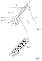
- a sheet or foil strip 2 is shown, which runs over a co-rotating measuring roller 3.
- the band 2 encloses a certain angular sector d ⁇ of the measuring roller 3 and, in this segment, causes a force F acting radially on the measuring roller 3, shown in arrows.
- a force profile 9 can be created, which can conclude on the flatness of the belt 2.
- a measuring roller 3 is shown again without band 2.
- it comprises a plurality of bores 4, which are arranged just below the surface of the measuring roller 3.
- These holes 4 are equipped over their entire length with force measuring sensors 5, which are suitable to measure the force F from the belt 2 to the measuring roller 3 in the required sensitivity.
- force measuring sensors 5 are used for this purpose. These must be under high tension be installed so that they can reliably measure.
- the heating or cooling of the measuring roller 3 by the belt 2 leads to an expansion of the measuring roller 3 on the surface. This leads to a change in the bias voltage V, which in turn causes a change in the force shunt on the force sensor. Since the sensitivity of the force sensor 5 is dependent on the respectively prevailing force shunt, the calibration values of the first force sensor 5 change over time.
- Fig. 6 an example of the bias voltage V as a function of the temperature T of the measuring roller 3 is indicated.
- the sensitivity E at the respective bias voltage V is indicated. If the bias corresponds to V0 to V1 of the situation during calibration, then the current sensitivity E is equal to the measurement during the calibration. In many cases, the calibration is performed in the situation where the measuring roller 3 has room temperature. However, the application of the measuring roller 3 takes place at strongly fluctuating temperatures with the consequence that the current sensitivity E deviates from the value of the calibration.
- a second force sensor 6 is integrated together with the first force sensor 5 in a force sensor system 1.
- this second force sensor 6 is intended to be a statically measuring force sensor which can reliably measure forces over long periods.
- the second Sensor 6 is a resistive, optical or resonant sensor. In particular, this may be a DMS sensor.
- Fig. 3 are the two force sensors 5, 6 arranged side by side, relative to the axis of the bore 4, respectively. the measuring roller 3.
- a biasing device 7 puts both force sensors 5, 6 under the same bias.
- Fig. 4 are the two force sensors 5, 6 arranged one above the other, based on the force introduction direction 8, which acts radially on the measuring roller 3.
- a pretensioning device 7 also displaces both force sensors 5, 6 under the same pretension.
- the advantage of this arrangement over the arrangement in Fig. 3 is that both force sensors 5, 6 are in the same power flow F, they are thus installed in series. Thus, it is always ensured that the bias on both force sensors 5, 6 is identical.
- the force sensors 5, 6 are preferably both designed as cylindrical discs with the same base surface 10, wherein their axes 11 co-axial and radial to the measuring roller 3 are arranged.
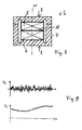
- Fig. 5 shows the arrangement of Fig. 4 in cross section.
- a biasing element one can be used in the prior art, such as in the WO2004 / 065924 described.
- the type of bias voltage will not be discussed in detail. It is only noted that it is essential, each individual force sensor system 1, which is installed in each hole 4 of the measuring roller 3, with enough larger Bias to provide. Since each hole 4 must be equipped with a variety of such force sensor systems 1, the type of attachment of the bias voltage is thus not insignificant.
- both signals of both force sensors 5, 6 are determined.
- Fig. 7 shows these time-dependent signals F 1 , F 2 of the first and second sensors 5, 6 in the two upper diagrams. Between the first two signals and the last signal shown relatively much time passes in which the temperature T of the measuring roller 3 varies greatly. The bias voltage V behaves accordingly, first falling, then increasing. The lower diagram shows the angular position ⁇ as a function of time. This need not be determined separately, but for the sake of clarity this is shown here.
- the upper curve shows the measuring signal F 1 of the first force sensor 5, which represents the force of the belt 2 on the measuring roller 3, while the force sensor system 1 is in the angular segment d ⁇ of the wrap angle 12 of the belt 2. Since this force sensor 5 must be highly sensitive, it is preferably a piezoelectric force sensor. This must be reset after each revolution with a reset to zero, as shown in the graph.
- the middle curve shows the measuring signal F 2 of the second force sensor 6, whose sensitivity is for example a hundred times lower than that of the first force sensor 5. From this signal, the biasing force V is now taken. This is the force that prevails while the force sensor system 1 is outside the angular segment d ⁇ of the wrap angle 12 of the belt 2. This constant value is the preload force V.
- the current sensitivity E of the first force sensor 5 is now determined by means of the currently determined biasing force of the second force sensor 6.
- the detected force signal can now be evaluated in an evaluation unit, not shown, on the basis of the current, determined sensitivity E with the correct calibration values.
- the angular position ⁇ of the measuring roller 3 can either be determined separately or it can be taken from the measurement signal of the second sensor 6.
- the force sensor system 1 may be a single sensor in which the two sensors 5, 6 are integrated.
- the first sensor 5 may also be a dynamic force sensor and the second sensor 6 may be an actuator.
- FIG. Fig. 4 built-in or in Fig. 8 shown as such
- the static measuring sensor 6 can then each measure the prevailing at the time of measurement preload, which are composed of the bias voltage v on the force sensor system 1 and an additional statically acting load.
- This static load can be caused by installation in a component 3 or by another static load acting on the location of the force sensor system 1.
- An example of a corresponding statistic signal F2 is in Fig. 9 shown.
- the measurement times in such applications are usually very long, for example, it is measured over months or years.
- the dynamic signal F1 superimposed on this static signal F2 is also in Fig. 9 shown. It comes with the second Force sensor 6 mitgemessen, but since the amplitude of F1 is about 6 orders of magnitude lower (10 ⁇ 6), the dynamic signal F1 the static signal F2 is not apparent.
- the static signal F2, measured with the second, static sensor 6, can be used in particular to check the quality of the dynamic signal F1, measured with the dynamic first sensor 5. If the bias voltage V or preload, ie the static load F2 falls below a critical value in which the sensitivity E of the first, dynamic sensor 5 is no longer in linear relationship to the bias voltage V, the measurement data of the first force sensor 5 can still be based on known characteristic with corrected reference values are evaluated. However, should the preload F2 decrease too much, it can be recognized that the data supplied by the first force sensor 5 are no longer usable. At a later time, when F2 returns higher values, it can be recognized that the signals F1 can be recycled again.
- the claimed in the claims force sensor system 1 can therefore according to the invention also be used for other applications than in the film and sheet metal processing and installed in any components 3.
- the biasing device can be applied through the component.
Landscapes
- Physics & Mathematics (AREA)
- General Physics & Mathematics (AREA)
- Engineering & Computer Science (AREA)
- Mechanical Engineering (AREA)
- Force Measurement Appropriate To Specific Purposes (AREA)
Priority Applications (1)
| Application Number | Priority Date | Filing Date | Title |
|---|---|---|---|
| EP14177548.6A EP2811277B1 (de) | 2010-12-22 | 2011-12-21 | Kraftsensorsystem und Verfahren zum Messung von Kräften und Folien- oder Blechbändern beim Walzen |
Applications Claiming Priority (2)
| Application Number | Priority Date | Filing Date | Title |
|---|---|---|---|
| CH02145/10A CH704255A1 (de) | 2010-12-22 | 2010-12-22 | Kraftsensorsystem und verfahren für planheitsmessungen von folien- oder blechbändern beim walzen. |
| PCT/CH2011/000306 WO2012083472A1 (de) | 2010-12-22 | 2011-12-21 | Kraftsensorsystem und verfahren zur messung von kräften von folien- oder blechbändern beim walzen |
Related Child Applications (2)
| Application Number | Title | Priority Date | Filing Date |
|---|---|---|---|
| EP14177548.6A Division-Into EP2811277B1 (de) | 2010-12-22 | 2011-12-21 | Kraftsensorsystem und Verfahren zum Messung von Kräften und Folien- oder Blechbändern beim Walzen |
| EP14177548.6A Division EP2811277B1 (de) | 2010-12-22 | 2011-12-21 | Kraftsensorsystem und Verfahren zum Messung von Kräften und Folien- oder Blechbändern beim Walzen |
Publications (2)
| Publication Number | Publication Date |
|---|---|
| EP2656036A1 EP2656036A1 (de) | 2013-10-30 |
| EP2656036B1 true EP2656036B1 (de) | 2015-09-09 |
Family
ID=43827136
Family Applications (2)
| Application Number | Title | Priority Date | Filing Date |
|---|---|---|---|
| EP11804913.9A Not-in-force EP2656036B1 (de) | 2010-12-22 | 2011-12-21 | Kraftsensorsystem und verfahren zur messung von kräften von folien- oder blechbändern beim walzen |
| EP14177548.6A Active EP2811277B1 (de) | 2010-12-22 | 2011-12-21 | Kraftsensorsystem und Verfahren zum Messung von Kräften und Folien- oder Blechbändern beim Walzen |
Family Applications After (1)
| Application Number | Title | Priority Date | Filing Date |
|---|---|---|---|
| EP14177548.6A Active EP2811277B1 (de) | 2010-12-22 | 2011-12-21 | Kraftsensorsystem und Verfahren zum Messung von Kräften und Folien- oder Blechbändern beim Walzen |
Country Status (6)
| Country | Link |
|---|---|
| US (1) | US9440270B2 (enExample) |
| EP (2) | EP2656036B1 (enExample) |
| JP (2) | JP5926740B2 (enExample) |
| CN (2) | CN104226700B (enExample) |
| CH (1) | CH704255A1 (enExample) |
| WO (1) | WO2012083472A1 (enExample) |
Families Citing this family (16)
| Publication number | Priority date | Publication date | Assignee | Title |
|---|---|---|---|---|
| AT511330B1 (de) | 2011-06-03 | 2012-11-15 | Piezocryst Advanced Sensorics | Sensor für die messung von druck und/oder kraft |
| DE102012014971A1 (de) * | 2012-07-30 | 2014-01-30 | Vdeh-Betriebsforschungsinstitut Gmbh | Messrolle und Verfahren zum Feststellen von Planheitsabweichungen beim Behandeln von bandförmigem Gut und Verwendung einer Messrolle |
| JP6217127B2 (ja) | 2013-05-10 | 2017-10-25 | 横浜ゴム株式会社 | コンベヤベルトの支持ローラ接触状態測定装置 |
| CN103302112B (zh) * | 2013-05-31 | 2015-09-16 | 燕山大学 | 整辊内嵌式板形仪 |
| CH709459A1 (de) * | 2014-04-02 | 2015-10-15 | Kistler Holding Ag | Vorspannvorrichtung einer Kraftmessvorrichtung, Kraftmessvorrichtung und Verfahren zu deren Einführung in Aussparungen von Maschinenteilen. |
| DE102014115023A1 (de) * | 2014-10-16 | 2016-04-21 | Bwg Bergwerk- Und Walzwerk-Maschinenbau Gmbh | Planheitsmessrolle mit Messbalken in Bandlaufrichtung |
| CN104785545B (zh) * | 2015-04-20 | 2017-01-11 | 中冶南方工程技术有限公司 | 一种接触式板形辊测量信号综合处理方法和装置 |
| CN105203237B (zh) * | 2015-10-16 | 2017-12-26 | 中航电测仪器股份有限公司 | 一种适用于轧制力传感器的应变计及其制造方法 |
| DE102017130769B4 (de) * | 2017-12-20 | 2021-09-09 | Bernd Berger | Messrolle |
| FR3077999B1 (fr) * | 2018-02-22 | 2020-03-20 | Commissariat A L'energie Atomique Et Aux Energies Alternatives | Rouleau de planeite, systeme de mesure de planeite et ligne d'operations de laminage associes |
| DE102018009611A1 (de) | 2018-12-11 | 2020-06-18 | Vdeh-Betriebsforschungsinstitut Gmbh | Messrolle zum Feststellen einer Eigenschaft eines über die Messrolle geführten bandförmigen Guts |
| DE102018009610A1 (de) | 2018-12-11 | 2020-06-18 | Vdeh-Betriebsforschungsinstitut Gmbh | Verfahren zum Feststellen einer Eigenschaft eines über die Messrolle geführten bandförmigen Guts |
| JP7135991B2 (ja) * | 2019-04-25 | 2022-09-13 | トヨタ自動車株式会社 | 校正判断装置、及び校正判断方法 |
| CN215262190U (zh) * | 2021-07-26 | 2021-12-21 | 宁德时代新能源科技股份有限公司 | 一种检测装置及极片延展设备 |
| CN114061429B (zh) * | 2021-11-26 | 2024-04-16 | 江西凯安智能股份有限公司 | 一种铜板带加工用高精度自动化尺寸检测装置 |
| DE102022203100A1 (de) * | 2022-03-30 | 2023-10-05 | Sms Group Gmbh | Walzgerüst und Verfahren zu dessen Betrieb |
Family Cites Families (13)
| Publication number | Priority date | Publication date | Assignee | Title |
|---|---|---|---|---|
| FR2314471A1 (fr) * | 1975-06-13 | 1977-01-07 | Secim | Rouleau deflecteur pour la mesure et le controle de la planeite d'une tole tendue en deplacement |
| AT369900B (de) * | 1981-05-20 | 1983-02-10 | List Hans | Messwertaufnehmer mit piezoelektrischem sensorelement |
| JPS60121401U (ja) * | 1984-01-25 | 1985-08-16 | 株式会社神戸製鋼所 | 多段圧延機 |
| CH680421A5 (enExample) * | 1989-12-22 | 1992-08-31 | Kistler Instrumente Ag | |
| JP3535967B2 (ja) * | 1998-01-19 | 2004-06-07 | 株式会社神戸製鋼所 | 圧延材の形状検出装置及び形状検出方法 |
| US20020104611A1 (en) | 1998-10-30 | 2002-08-08 | Adams Thomas C. | Self-flattening screens for vibratory separators |
| DE19918699B4 (de) * | 1999-04-26 | 2008-03-27 | Betriebsforschungsinstitut VDEh - Institut für angewandte Forschung GmbH | Meßrolle zum Feststellen von Planheitsabweichungen |
| US6299571B1 (en) * | 1999-10-22 | 2001-10-09 | Morrison Berkshire, Inc. | System and method for controlling deflection of a dynamic surface |
| FR2823300B1 (fr) * | 2001-04-10 | 2003-09-05 | Vai Clecim | Procede de detection de defauts de planeite |
| DE10207501C1 (de) * | 2002-01-22 | 2003-10-23 | Bfi Vdeh Inst Angewandte Forschung Gmbh | Vollrolle zum Feststellen von Planheitsabweichungen |
| ATE539334T1 (de) * | 2003-01-17 | 2012-01-15 | Kistler Holding Ag | Vorspannelement für sensoren |
| DE102006003792B4 (de) * | 2006-01-25 | 2013-11-14 | Betriebsforschungsinstitut VDEh Institut für angewandte Forschung Gesellschaft mit beschränkter Haftung | Halterung für einen Drucksensor sowie Meßrolle mit einem Drucksensor |
| ES2342553T3 (es) * | 2006-12-02 | 2010-07-08 | Texmag Gmbh Vertriebsgesellschaft | Rodillo con un sensor de fuerza. |
-
2010
- 2010-12-22 CH CH02145/10A patent/CH704255A1/de not_active Application Discontinuation
-
2011
- 2011-12-21 CN CN201410415222.XA patent/CN104226700B/zh not_active Expired - Fee Related
- 2011-12-21 US US13/996,176 patent/US9440270B2/en not_active Expired - Fee Related
- 2011-12-21 CN CN201180062020.6A patent/CN103270401B/zh not_active Expired - Fee Related
- 2011-12-21 JP JP2013544991A patent/JP5926740B2/ja not_active Expired - Fee Related
- 2011-12-21 WO PCT/CH2011/000306 patent/WO2012083472A1/de not_active Ceased
- 2011-12-21 EP EP11804913.9A patent/EP2656036B1/de not_active Not-in-force
- 2011-12-21 EP EP14177548.6A patent/EP2811277B1/de active Active
-
2014
- 2014-08-28 JP JP2014174161A patent/JP5837968B2/ja not_active Expired - Fee Related
Also Published As
| Publication number | Publication date |
|---|---|
| CN104226700B (zh) | 2017-07-25 |
| CN103270401A (zh) | 2013-08-28 |
| JP5926740B2 (ja) | 2016-05-25 |
| US9440270B2 (en) | 2016-09-13 |
| JP5837968B2 (ja) | 2015-12-24 |
| JP2014219425A (ja) | 2014-11-20 |
| CN103270401B (zh) | 2015-07-01 |
| US20130298625A1 (en) | 2013-11-14 |
| WO2012083472A1 (de) | 2012-06-28 |
| CH704255A1 (de) | 2012-06-29 |
| EP2811277A3 (de) | 2015-03-11 |
| JP2014505240A (ja) | 2014-02-27 |
| EP2811277B1 (de) | 2016-12-14 |
| EP2656036A1 (de) | 2013-10-30 |
| CN104226700A (zh) | 2014-12-24 |
| EP2811277A2 (de) | 2014-12-10 |
| EP2811277A9 (de) | 2016-06-15 |
Similar Documents
| Publication | Publication Date | Title |
|---|---|---|
| EP2656036B1 (de) | Kraftsensorsystem und verfahren zur messung von kräften von folien- oder blechbändern beim walzen | |
| DE2232983A1 (de) | Vorrichtung zum messen der spannung einer laufenden materialbahn, eines drahtes oder dergl | |
| EP1369186A2 (de) | Verfahren und Vorrichtung zur Planheitsmessung von Bändern | |
| WO2015131862A1 (de) | Bauteil mit einem wenigstens einen sensor aufweisenden messelement | |
| EP2054707B1 (de) | Gleichförmigkeits-messmaschine für fahrzeugreifen | |
| EP1640696A1 (de) | Drucksensor | |
| DE102018106563A1 (de) | Verfahren zur Messwertkompensation bei kapazitiven Druckmesszellen | |
| WO2008071578A1 (de) | Separate erfassung von zuspann- und reibkräften an einer bremse | |
| DE2729338A1 (de) | Walzspaltmess- und -regelvorrichtung | |
| EP3161445A1 (de) | Prüfvorrichtung zum prüfen von schraubsystemen und prüfverfahren dafür | |
| DE102004008303A1 (de) | Verfahren zur Ermittlung von Planheitsfehlern in Bändern, insbesondere Stahl- und Metallbändern, und Planheitsmessrolle | |
| EP0682235B1 (de) | Verfahren und Vorrichtung zum Abgleich eines Messkörpers eines Messwertaufnehmers | |
| EP2253567B1 (de) | Vorrichtung zum kontinuierlichen Aufwickeln einer Faserstoffbahn | |
| DE102004033925B4 (de) | Drehmoment-Messaufnehmer | |
| DE102010012701B4 (de) | Mikrokraftsensor | |
| WO2018219382A1 (de) | Vorspannungsmessung mit kraftmessbolzen | |
| DE102013113173A1 (de) | Dehnungselement, Lastmesszelle und Messvorrichtung | |
| DE102008025287A1 (de) | Vorrichtung zur Messung von Pressungskenngrößen im Spalt zwischen zylindrischen Körpern | |
| DE2744810A1 (de) | Stellungsfuehler fuer einen hydraulikzylinder | |
| DE10157792B4 (de) | Verfahren und Messrolle zur Messung der Bandzugspannung und/oder der Bandtemperatur über die Bandbreite für eine Bandplanheitsregelung beim Walzen von Bandmaterial | |
| EP1336829A2 (de) | Vorrichtung zum Messen einer Axialkraft an einer Achse oder Welle | |
| WO2008037249A1 (de) | Prüfvorrichtung für die montage eines maschinenelements mit einer axialbohrung | |
| DE102010024806B4 (de) | Drehmoment-Messeinrichtung und Verfahren zur Drehmomentmessung | |
| EP4313701B1 (de) | Stützwinde mit einem kraftmesselement | |
| DE3546480C2 (de) | Meßeinrichtung für die Wickelhärte eines Wickels |
Legal Events
| Date | Code | Title | Description |
|---|---|---|---|
| PUAI | Public reference made under article 153(3) epc to a published international application that has entered the european phase |
Free format text: ORIGINAL CODE: 0009012 |
|
| 17P | Request for examination filed |
Effective date: 20130708 |
|
| AK | Designated contracting states |
Kind code of ref document: A1 Designated state(s): AL AT BE BG CH CY CZ DE DK EE ES FI FR GB GR HR HU IE IS IT LI LT LU LV MC MK MT NL NO PL PT RO RS SE SI SK SM TR |
|
| DAX | Request for extension of the european patent (deleted) | ||
| REG | Reference to a national code |
Ref country code: DE Ref legal event code: R079 Ref document number: 502011007855 Country of ref document: DE Free format text: PREVIOUS MAIN CLASS: G01L0005040000 Ipc: G01L0005000000 |
|
| GRAP | Despatch of communication of intention to grant a patent |
Free format text: ORIGINAL CODE: EPIDOSNIGR1 |
|
| GRAJ | Information related to disapproval of communication of intention to grant by the applicant or resumption of examination proceedings by the epo deleted |
Free format text: ORIGINAL CODE: EPIDOSDIGR1 |
|
| GRAP | Despatch of communication of intention to grant a patent |
Free format text: ORIGINAL CODE: EPIDOSNIGR1 |
|
| RIC1 | Information provided on ipc code assigned before grant |
Ipc: B21B 38/02 20060101ALI20150116BHEP Ipc: G01L 5/00 20060101AFI20150116BHEP Ipc: B21B 38/08 20060101ALI20150116BHEP Ipc: G01L 5/04 20060101ALI20150116BHEP |
|
| INTG | Intention to grant announced |
Effective date: 20150205 |
|
| INTG | Intention to grant announced |
Effective date: 20150218 |
|
| GRAP | Despatch of communication of intention to grant a patent |
Free format text: ORIGINAL CODE: EPIDOSNIGR1 |
|
| INTG | Intention to grant announced |
Effective date: 20150429 |
|
| GRAS | Grant fee paid |
Free format text: ORIGINAL CODE: EPIDOSNIGR3 |
|
| GRAA | (expected) grant |
Free format text: ORIGINAL CODE: 0009210 |
|
| AK | Designated contracting states |
Kind code of ref document: B1 Designated state(s): AL AT BE BG CH CY CZ DE DK EE ES FI FR GB GR HR HU IE IS IT LI LT LU LV MC MK MT NL NO PL PT RO RS SE SI SK SM TR |
|
| REG | Reference to a national code |
Ref country code: GB Ref legal event code: FG4D Free format text: NOT ENGLISH |
|
| REG | Reference to a national code |
Ref country code: AT Ref legal event code: REF Ref document number: 748511 Country of ref document: AT Kind code of ref document: T Effective date: 20150915 Ref country code: CH Ref legal event code: EP |
|
| REG | Reference to a national code |
Ref country code: IE Ref legal event code: FG4D Free format text: LANGUAGE OF EP DOCUMENT: GERMAN |
|
| REG | Reference to a national code |
Ref country code: DE Ref legal event code: R096 Ref document number: 502011007855 Country of ref document: DE |
|
| REG | Reference to a national code |
Ref country code: SE Ref legal event code: TRGR |
|
| REG | Reference to a national code |
Ref country code: FR Ref legal event code: PLFP Year of fee payment: 5 |
|
| REG | Reference to a national code |
Ref country code: NL Ref legal event code: MP Effective date: 20150909 |
|
| PG25 | Lapsed in a contracting state [announced via postgrant information from national office to epo] |
Ref country code: NO Free format text: LAPSE BECAUSE OF FAILURE TO SUBMIT A TRANSLATION OF THE DESCRIPTION OR TO PAY THE FEE WITHIN THE PRESCRIBED TIME-LIMIT Effective date: 20151209 Ref country code: GR Free format text: LAPSE BECAUSE OF FAILURE TO SUBMIT A TRANSLATION OF THE DESCRIPTION OR TO PAY THE FEE WITHIN THE PRESCRIBED TIME-LIMIT Effective date: 20151210 Ref country code: LT Free format text: LAPSE BECAUSE OF FAILURE TO SUBMIT A TRANSLATION OF THE DESCRIPTION OR TO PAY THE FEE WITHIN THE PRESCRIBED TIME-LIMIT Effective date: 20150909 Ref country code: LV Free format text: LAPSE BECAUSE OF FAILURE TO SUBMIT A TRANSLATION OF THE DESCRIPTION OR TO PAY THE FEE WITHIN THE PRESCRIBED TIME-LIMIT Effective date: 20150909 Ref country code: FI Free format text: LAPSE BECAUSE OF FAILURE TO SUBMIT A TRANSLATION OF THE DESCRIPTION OR TO PAY THE FEE WITHIN THE PRESCRIBED TIME-LIMIT Effective date: 20150909 |
|
| REG | Reference to a national code |
Ref country code: LT Ref legal event code: MG4D |
|
| PG25 | Lapsed in a contracting state [announced via postgrant information from national office to epo] |
Ref country code: HR Free format text: LAPSE BECAUSE OF FAILURE TO SUBMIT A TRANSLATION OF THE DESCRIPTION OR TO PAY THE FEE WITHIN THE PRESCRIBED TIME-LIMIT Effective date: 20150909 Ref country code: RS Free format text: LAPSE BECAUSE OF FAILURE TO SUBMIT A TRANSLATION OF THE DESCRIPTION OR TO PAY THE FEE WITHIN THE PRESCRIBED TIME-LIMIT Effective date: 20150909 Ref country code: ES Free format text: LAPSE BECAUSE OF FAILURE TO SUBMIT A TRANSLATION OF THE DESCRIPTION OR TO PAY THE FEE WITHIN THE PRESCRIBED TIME-LIMIT Effective date: 20150909 |
|
| PG25 | Lapsed in a contracting state [announced via postgrant information from national office to epo] |
Ref country code: NL Free format text: LAPSE BECAUSE OF FAILURE TO SUBMIT A TRANSLATION OF THE DESCRIPTION OR TO PAY THE FEE WITHIN THE PRESCRIBED TIME-LIMIT Effective date: 20150909 |
|
| PG25 | Lapsed in a contracting state [announced via postgrant information from national office to epo] |
Ref country code: SK Free format text: LAPSE BECAUSE OF FAILURE TO SUBMIT A TRANSLATION OF THE DESCRIPTION OR TO PAY THE FEE WITHIN THE PRESCRIBED TIME-LIMIT Effective date: 20150909 Ref country code: EE Free format text: LAPSE BECAUSE OF FAILURE TO SUBMIT A TRANSLATION OF THE DESCRIPTION OR TO PAY THE FEE WITHIN THE PRESCRIBED TIME-LIMIT Effective date: 20150909 Ref country code: CZ Free format text: LAPSE BECAUSE OF FAILURE TO SUBMIT A TRANSLATION OF THE DESCRIPTION OR TO PAY THE FEE WITHIN THE PRESCRIBED TIME-LIMIT Effective date: 20150909 Ref country code: IS Free format text: LAPSE BECAUSE OF FAILURE TO SUBMIT A TRANSLATION OF THE DESCRIPTION OR TO PAY THE FEE WITHIN THE PRESCRIBED TIME-LIMIT Effective date: 20160109 |
|
| PG25 | Lapsed in a contracting state [announced via postgrant information from national office to epo] |
Ref country code: BE Free format text: LAPSE BECAUSE OF NON-PAYMENT OF DUE FEES Effective date: 20151231 Ref country code: RO Free format text: LAPSE BECAUSE OF FAILURE TO SUBMIT A TRANSLATION OF THE DESCRIPTION OR TO PAY THE FEE WITHIN THE PRESCRIBED TIME-LIMIT Effective date: 20150909 Ref country code: PT Free format text: LAPSE BECAUSE OF FAILURE TO SUBMIT A TRANSLATION OF THE DESCRIPTION OR TO PAY THE FEE WITHIN THE PRESCRIBED TIME-LIMIT Effective date: 20160111 Ref country code: PL Free format text: LAPSE BECAUSE OF FAILURE TO SUBMIT A TRANSLATION OF THE DESCRIPTION OR TO PAY THE FEE WITHIN THE PRESCRIBED TIME-LIMIT Effective date: 20150909 |
|
| REG | Reference to a national code |
Ref country code: DE Ref legal event code: R097 Ref document number: 502011007855 Country of ref document: DE |
|
| PLBE | No opposition filed within time limit |
Free format text: ORIGINAL CODE: 0009261 |
|
| STAA | Information on the status of an ep patent application or granted ep patent |
Free format text: STATUS: NO OPPOSITION FILED WITHIN TIME LIMIT |
|
| PG25 | Lapsed in a contracting state [announced via postgrant information from national office to epo] |
Ref country code: MC Free format text: LAPSE BECAUSE OF FAILURE TO SUBMIT A TRANSLATION OF THE DESCRIPTION OR TO PAY THE FEE WITHIN THE PRESCRIBED TIME-LIMIT Effective date: 20150909 Ref country code: LU Free format text: LAPSE BECAUSE OF FAILURE TO SUBMIT A TRANSLATION OF THE DESCRIPTION OR TO PAY THE FEE WITHIN THE PRESCRIBED TIME-LIMIT Effective date: 20151221 |
|
| 26N | No opposition filed |
Effective date: 20160610 |
|
| PG25 | Lapsed in a contracting state [announced via postgrant information from national office to epo] |
Ref country code: DK Free format text: LAPSE BECAUSE OF FAILURE TO SUBMIT A TRANSLATION OF THE DESCRIPTION OR TO PAY THE FEE WITHIN THE PRESCRIBED TIME-LIMIT Effective date: 20150909 Ref country code: SI Free format text: LAPSE BECAUSE OF FAILURE TO SUBMIT A TRANSLATION OF THE DESCRIPTION OR TO PAY THE FEE WITHIN THE PRESCRIBED TIME-LIMIT Effective date: 20150909 |
|
| REG | Reference to a national code |
Ref country code: IE Ref legal event code: MM4A |
|
| PG25 | Lapsed in a contracting state [announced via postgrant information from national office to epo] |
Ref country code: IE Free format text: LAPSE BECAUSE OF NON-PAYMENT OF DUE FEES Effective date: 20151221 |
|
| REG | Reference to a national code |
Ref country code: FR Ref legal event code: PLFP Year of fee payment: 6 |
|
| PG25 | Lapsed in a contracting state [announced via postgrant information from national office to epo] |
Ref country code: SM Free format text: LAPSE BECAUSE OF FAILURE TO SUBMIT A TRANSLATION OF THE DESCRIPTION OR TO PAY THE FEE WITHIN THE PRESCRIBED TIME-LIMIT Effective date: 20150909 Ref country code: BG Free format text: LAPSE BECAUSE OF FAILURE TO SUBMIT A TRANSLATION OF THE DESCRIPTION OR TO PAY THE FEE WITHIN THE PRESCRIBED TIME-LIMIT Effective date: 20150909 Ref country code: HU Free format text: LAPSE BECAUSE OF FAILURE TO SUBMIT A TRANSLATION OF THE DESCRIPTION OR TO PAY THE FEE WITHIN THE PRESCRIBED TIME-LIMIT; INVALID AB INITIO Effective date: 20111221 |
|
| PG25 | Lapsed in a contracting state [announced via postgrant information from national office to epo] |
Ref country code: CY Free format text: LAPSE BECAUSE OF FAILURE TO SUBMIT A TRANSLATION OF THE DESCRIPTION OR TO PAY THE FEE WITHIN THE PRESCRIBED TIME-LIMIT Effective date: 20150909 |
|
| PG25 | Lapsed in a contracting state [announced via postgrant information from national office to epo] |
Ref country code: MT Free format text: LAPSE BECAUSE OF FAILURE TO SUBMIT A TRANSLATION OF THE DESCRIPTION OR TO PAY THE FEE WITHIN THE PRESCRIBED TIME-LIMIT Effective date: 20150909 |
|
| REG | Reference to a national code |
Ref country code: FR Ref legal event code: PLFP Year of fee payment: 7 |
|
| PG25 | Lapsed in a contracting state [announced via postgrant information from national office to epo] |
Ref country code: MK Free format text: LAPSE BECAUSE OF FAILURE TO SUBMIT A TRANSLATION OF THE DESCRIPTION OR TO PAY THE FEE WITHIN THE PRESCRIBED TIME-LIMIT Effective date: 20150909 |
|
| PG25 | Lapsed in a contracting state [announced via postgrant information from national office to epo] |
Ref country code: TR Free format text: LAPSE BECAUSE OF FAILURE TO SUBMIT A TRANSLATION OF THE DESCRIPTION OR TO PAY THE FEE WITHIN THE PRESCRIBED TIME-LIMIT Effective date: 20150909 Ref country code: AL Free format text: LAPSE BECAUSE OF FAILURE TO SUBMIT A TRANSLATION OF THE DESCRIPTION OR TO PAY THE FEE WITHIN THE PRESCRIBED TIME-LIMIT Effective date: 20150909 |
|
| PGFP | Annual fee paid to national office [announced via postgrant information from national office to epo] |
Ref country code: DE Payment date: 20201211 Year of fee payment: 10 Ref country code: SE Payment date: 20201221 Year of fee payment: 10 Ref country code: FR Payment date: 20201223 Year of fee payment: 10 Ref country code: GB Payment date: 20201223 Year of fee payment: 10 Ref country code: AT Payment date: 20201222 Year of fee payment: 10 |
|
| PGFP | Annual fee paid to national office [announced via postgrant information from national office to epo] |
Ref country code: CH Payment date: 20210120 Year of fee payment: 10 Ref country code: IT Payment date: 20201224 Year of fee payment: 10 |
|
| REG | Reference to a national code |
Ref country code: DE Ref legal event code: R119 Ref document number: 502011007855 Country of ref document: DE |
|
| REG | Reference to a national code |
Ref country code: CH Ref legal event code: PL |
|
| REG | Reference to a national code |
Ref country code: SE Ref legal event code: EUG |
|
| REG | Reference to a national code |
Ref country code: AT Ref legal event code: MM01 Ref document number: 748511 Country of ref document: AT Kind code of ref document: T Effective date: 20211221 |
|
| GBPC | Gb: european patent ceased through non-payment of renewal fee |
Effective date: 20211221 |
|
| PG25 | Lapsed in a contracting state [announced via postgrant information from national office to epo] |
Ref country code: SE Free format text: LAPSE BECAUSE OF NON-PAYMENT OF DUE FEES Effective date: 20211222 Ref country code: GB Free format text: LAPSE BECAUSE OF NON-PAYMENT OF DUE FEES Effective date: 20211221 Ref country code: DE Free format text: LAPSE BECAUSE OF NON-PAYMENT OF DUE FEES Effective date: 20220701 Ref country code: AT Free format text: LAPSE BECAUSE OF NON-PAYMENT OF DUE FEES Effective date: 20211221 |
|
| PG25 | Lapsed in a contracting state [announced via postgrant information from national office to epo] |
Ref country code: FR Free format text: LAPSE BECAUSE OF NON-PAYMENT OF DUE FEES Effective date: 20211231 |
|
| PG25 | Lapsed in a contracting state [announced via postgrant information from national office to epo] |
Ref country code: LI Free format text: LAPSE BECAUSE OF NON-PAYMENT OF DUE FEES Effective date: 20211231 Ref country code: CH Free format text: LAPSE BECAUSE OF NON-PAYMENT OF DUE FEES Effective date: 20211231 |
|
| PG25 | Lapsed in a contracting state [announced via postgrant information from national office to epo] |
Ref country code: IT Free format text: LAPSE BECAUSE OF NON-PAYMENT OF DUE FEES Effective date: 20211221 |