EP2656019B1 - Device and method for determining a flow velocity of a fluid or a fluid component in a pipeline - Google Patents
Device and method for determining a flow velocity of a fluid or a fluid component in a pipeline Download PDFInfo
- Publication number
- EP2656019B1 EP2656019B1 EP11811411.5A EP11811411A EP2656019B1 EP 2656019 B1 EP2656019 B1 EP 2656019B1 EP 11811411 A EP11811411 A EP 11811411A EP 2656019 B1 EP2656019 B1 EP 2656019B1
- Authority
- EP
- European Patent Office
- Prior art keywords
- fluid
- signal
- receiver
- fluid component
- pipeline
- Prior art date
- Legal status (The legal status is an assumption and is not a legal conclusion. Google has not performed a legal analysis and makes no representation as to the accuracy of the status listed.)
- Active
Links
- 239000012530 fluid Substances 0.000 title claims description 246
- 238000000034 method Methods 0.000 title claims description 28
- 238000002604 ultrasonography Methods 0.000 claims description 100
- 238000005259 measurement Methods 0.000 claims description 32
- 239000006185 dispersion Substances 0.000 claims description 21
- 241000237858 Gastropoda Species 0.000 claims description 18
- 239000007789 gas Substances 0.000 description 28
- 239000007788 liquid Substances 0.000 description 18
- 239000003921 oil Substances 0.000 description 10
- VNWKTOKETHGBQD-UHFFFAOYSA-N methane Chemical compound C VNWKTOKETHGBQD-UHFFFAOYSA-N 0.000 description 6
- 230000001419 dependent effect Effects 0.000 description 5
- 238000010521 absorption reaction Methods 0.000 description 4
- 238000001914 filtration Methods 0.000 description 4
- 230000006870 function Effects 0.000 description 4
- 230000035515 penetration Effects 0.000 description 4
- 230000000694 effects Effects 0.000 description 3
- 238000011144 upstream manufacturing Methods 0.000 description 3
- IJGRMHOSHXDMSA-UHFFFAOYSA-N Atomic nitrogen Chemical compound N#N IJGRMHOSHXDMSA-UHFFFAOYSA-N 0.000 description 2
- 239000004215 Carbon black (E152) Substances 0.000 description 2
- 238000004581 coalescence Methods 0.000 description 2
- 230000003247 decreasing effect Effects 0.000 description 2
- 229930195733 hydrocarbon Natural products 0.000 description 2
- 150000002430 hydrocarbons Chemical class 0.000 description 2
- 238000004519 manufacturing process Methods 0.000 description 2
- 239000000203 mixture Substances 0.000 description 2
- 239000012071 phase Substances 0.000 description 2
- 238000000926 separation method Methods 0.000 description 2
- 239000003570 air Substances 0.000 description 1
- 238000004364 calculation method Methods 0.000 description 1
- 238000010276 construction Methods 0.000 description 1
- 239000010779 crude oil Substances 0.000 description 1
- 239000000839 emulsion Substances 0.000 description 1
- 238000005516 engineering process Methods 0.000 description 1
- 239000000446 fuel Substances 0.000 description 1
- 230000005484 gravity Effects 0.000 description 1
- 238000011065 in-situ storage Methods 0.000 description 1
- 239000007791 liquid phase Substances 0.000 description 1
- 229910052757 nitrogen Inorganic materials 0.000 description 1
- 230000000087 stabilizing effect Effects 0.000 description 1
- 239000000126 substance Substances 0.000 description 1
- XLYOFNOQVPJJNP-UHFFFAOYSA-N water Substances O XLYOFNOQVPJJNP-UHFFFAOYSA-N 0.000 description 1
Images


Classifications
-
- G—PHYSICS
- G01—MEASURING; TESTING
- G01F—MEASURING VOLUME, VOLUME FLOW, MASS FLOW OR LIQUID LEVEL; METERING BY VOLUME
- G01F1/00—Measuring the volume flow or mass flow of fluid or fluent solid material wherein the fluid passes through a meter in a continuous flow
- G01F1/66—Measuring the volume flow or mass flow of fluid or fluent solid material wherein the fluid passes through a meter in a continuous flow by measuring frequency, phase shift or propagation time of electromagnetic or other waves, e.g. using ultrasonic flowmeters
- G01F1/663—Measuring the volume flow or mass flow of fluid or fluent solid material wherein the fluid passes through a meter in a continuous flow by measuring frequency, phase shift or propagation time of electromagnetic or other waves, e.g. using ultrasonic flowmeters by measuring Doppler frequency shift
-
- G—PHYSICS
- G01—MEASURING; TESTING
- G01F—MEASURING VOLUME, VOLUME FLOW, MASS FLOW OR LIQUID LEVEL; METERING BY VOLUME
- G01F1/00—Measuring the volume flow or mass flow of fluid or fluent solid material wherein the fluid passes through a meter in a continuous flow
- G01F1/66—Measuring the volume flow or mass flow of fluid or fluent solid material wherein the fluid passes through a meter in a continuous flow by measuring frequency, phase shift or propagation time of electromagnetic or other waves, e.g. using ultrasonic flowmeters
- G01F1/662—Constructional details
-
- G—PHYSICS
- G01—MEASURING; TESTING
- G01F—MEASURING VOLUME, VOLUME FLOW, MASS FLOW OR LIQUID LEVEL; METERING BY VOLUME
- G01F1/00—Measuring the volume flow or mass flow of fluid or fluent solid material wherein the fluid passes through a meter in a continuous flow
- G01F1/74—Devices for measuring flow of a fluid or flow of a fluent solid material in suspension in another fluid
-
- G—PHYSICS
- G01—MEASURING; TESTING
- G01P—MEASURING LINEAR OR ANGULAR SPEED, ACCELERATION, DECELERATION, OR SHOCK; INDICATING PRESENCE, ABSENCE, OR DIRECTION, OF MOVEMENT
- G01P5/00—Measuring speed of fluids, e.g. of air stream; Measuring speed of bodies relative to fluids, e.g. of ship, of aircraft
Definitions
- the present invention relates to a measurement arrangement and a method for determining a flow velocity of a fluid or a fluid component in a pipeline.
- it may be applied in flows of crude oil and gas production and transportation systems, in chemical and petrochemical production, as well as in fuel and energy industries, etc.
- a method for measuring a flow velocity of a fluid in a pipeline known in the art is described below.
- the method implies probing a controlled volume of a fluid with ultrasonic pulses emitted by a first source (emitter) and travelling transversely to the pipeline axis.
- the pulses that have passed through a controlled volume are registered by a first pulse receiver located oppositely to the emitter.
- a second pair of an emitter and a pulse receiver is located downstream at a known distance from the first pair.
- the time interval in which the fluid flows from the first pair to the second pair can be determined. From this, the flow velocity is determined.
- a disadvantage of this method is that measuring the flow velocity using the cross correlation method is not possible in an unsteady flow, as in this case the cross correlation method is often inaccurate. This yields an inaccurate determination of the flow velocity.
- An objective of the invention is to provide a measurement arrangement and method for determining a flow velocity of a fluid or a fluid component in a pipeline with a higher accuracy of determining the flow velocity than the method described above.
- a measurement arrangement comprising a device for determining a flow velocity of a fluid (14) or a fluid component (2) in a pipeline (1), the device comprising
- the device comprises a transmitter for transmitting an ultrasound signal to a flowing fluid.
- the transmitter may be a piezo-electric transmitter or any other ultrasound transmitter.
- a fluid may be a liquid or a gas.
- the fluid may comprise multiple fluid components, being liquid and/or gas components.
- the present invention enables determining the flow velocity of a liquid component in a fluid comprising a liquid and a gas.
- Ultrasound is sound with a frequency greater than the upper limit of human hearing, approximately 20 kHz.
- a receiver e.g. a piezo-electric receiver.
- the frequency of the dispersed signal as received by the receiver will depend on frequency of the transmitted ultrasound signal and the velocity difference between (i) the transmitter and the fluid and (ii) the fluid and the receiver, according to the well-known Doppler principle.
- the transmitter and the receiver are adapted to be placed inside the pipeline.
- the transmitter and the receiver may be placed on a ring or other supporting construction that is to be placed inside the pipeline.
- the transmitter and the receiver may each comprise an connecting plate, which may be connected to the inside wall of the pipeline.
- the transmitter and receiver define a measurement volume having a comparatively small cross-section compared to the pipeline cross-section.
- Such measurement volume can e.g. be realized by arranging both the transmitter and receiver close to each other near a central position inside the pipeline. Note that such an arrangement is distinct from an arrangement whereby the transmitter and receiver are directly arranged on a surface of the pipeline, e.g. an inner or outer surface of the pipeline.
- the distance between the transmitter and the receiver, in a direction perpendicular to the flow direction is about 5 to 10% of the pipeline diameter.
- the transmitter and receiver are spaced apart over a distance of 2 to 10 mm. By positioning the transmitter and receiver at such close distance, facilitates the reception of signals even when they are strongly damped such as in water-oil emulsions.
- the transmitter, receiver and the measurement volume which can be considered a local, comparatively small volume, can be construed as forming a measurement chamber. By arranging the transmitter and receiver close to each other, the transducers only sense the flow inside the measurement chamber.
- the transmitter and receiver have a streamlined profile such as a wing shaped form, to mitigate flow disturbances.
- the transmitter and receiver can be connected to the pipeline via connecting rods or plates that may equally be shaped to avoid disturbances.
- the device further comprises a process unit that is arranged to determine the frequency of the dispersed ultrasound signal and to determine the velocity of the flow based on Doppler principle.
- a processing unit can e.g. comprise a microprocessor including a DSP (digital signal processor) or the like.
- the dispersed ultrasound signal will be generated in a volume around an intersection of the first direction and the second direction. Since this volume is relatively small compared to any spatial disturbances in the fluid, for example in an unsteady flow, the flow velocity in the volume is approximately uniform or constant (that is: constant in space, not necessarily in time). Therefore, the device according to the invention is capable of determining the flow velocity with a high accuracy, since the spatial disturbances will have little or no influence on the determination of the flow velocity.
- the first direction and the second direction intersect with each other, defining an intersection angle, the intersection angle being at least 10 degrees, or preferably at least 20 degrees, more preferably in the range of 10-45 degrees, or preferably at least 60 degrees, or more preferable in the range of 80 - 90 degrees.
- the determination of the flow velocity will be more accurate when the received dispersed ultrasound signal is generated in a small volume than in a larger volume.
- An advantage of a configuration of the transmitter and the receiver, in which the intersection angle between the first and the second direction is at least 10 degrees is that the volume wherein the dispersed ultrasound signal is generated is smaller than in a configuration with an intersection angle less than 10 degrees.
- the flow velocity defines a flow direction
- the first direction and the flow direction define an incident angle
- the second and the flow direction define a dispersion angle
- the incident angle is equal to the dispersion angle
- An advantage of this configuration is that the velocity difference between the transmitter and the fluid will be equal to the velocity difference between the fluid and the receiver. This enables a more easy calculation or determination of the flow velocity.
- the first direction, the second direction and the flow direction are coplanar.
- both the transmitter and the receiver are arranged to be placed inside the pipeline. Inside the pipeline, they may more or less cause disturbances in the flow.
- An advantage of the configuration in one plane, is that the transmitter and the receiver cause less turbulence or disturbances when they are placed symmetric about the flow direction.
- the measurement arrangement comprises a first pipeline segment connected to a second pipeline segment, whereby the device is arranged inside the second segment.
- the first pipeline segment is mounted in a substantially horizontal direction and the second pipeline segment extends in a substantially vertical direction, the first pipeline segment being arranged to receive the fluid or fluid component and provide the fluid or fluid component to the second pipeline segment.
- the transmitter and receiver and the measurement volume are thus, in use, arranged inside a vertical pipeline segment.
- a horizontal pipeline section also referred to as a pipe pre-section enables to form gas slugs in case of a gas-liquid flow is applied.
- the use of the horizontal pre-section helps to separate gas and liquid phases (if present) in the fluid flow along the pipe and provides for an alternate arrival of the liquid and gas into the measurement chamber.
- the horizontal pre-section can be used to stabilize the flow and provide in a partial coalescence of the gas phase (if present).
- a slug flow pattern of a multiphase flow can be obtained in a wide range of gas and liquid flow rates.
- the fluid comprises a first fluid component and a second fluid component.
- the first and the second fluid component may be a liquid or a gas.
- the fluid may therefore be a combination of a liquid and gas, but also combinations of two different liquids or two different gasses are possible. It may be the case that the velocity of the first component is different from the velocity of the second component.
- the processing unit is further arranged to determine a fraction describing the ratio of a volume of the first fluid component of the fluid and a volume of the second fluid component of the fluid.
- An advantage of this arrangement is that it enables the determination of the flow rate of one of the components of the fluid, since the flow rate of a component in a fluid is dependent on the volume of the component in the fluid and the flow velocity of this component.
- the processing unit is further arranged to determine a flow rate of the first fluid component based on the flow velocity of the first fluid component and said fraction.
- the arrangement of the transmitter and the receiver define a measuring volume arranged to contain the fluid or the fluid component; the transmitter is arranged to transmit the ultrasound signal into said measuring volume in the first direction; and, the receiver is arranged to receive the dispersed ultrasound signal from said measuring volume in the second direction.
- the transmitter Since the transmitter is arranged to transmit the ultrasound signal in the first direction and the path of the transmitted ultrasound signal is limited by absorption and dispersion, the transmitter defines a transmitting volume in which the ultrasound signal is transmitted. Likewise, since the receiver is arranged to receive the dispersed ultrasound signal in the second direction and the path of the dispersed ultrasound signal is limited by absorption and dispersion, the receiver defines a receiving volume from which a dispersed ultrasound signal is received.
- the overlap of the transmitting volume and the receiving volume is referred to as measuring volume, since it is the fluid in the measuring volume that, after having received the transmitted ultrasound signal, generates the dispersed ultrasound signal that is received by the receiver.
- the device further comprises a measuring chamber, the measuring chamber comprising a measuring volume arranged to contain the fluid or the fluid component; wherein the transmitter is arranged to transmit the ultrasound signal into said measuring volume in the first direction and the receiver is arranged to receive the dispersed ultrasound signal from said measuring volume in the second direction.
- An advantage of this embodiment is that the measuring volume is physically limited by a measuring chamber. In that way, the size, dimensions and/or location of the measuring volume may be controlled. The size, dimensions and/or location of the measuring chamber may be adjustable or may be determined before use.
- the measuring volume is smaller than or equal to an average volume of fluid slugs.
- the first or the second fluid component may comprise fluid slugs, that is a comparatively large continuous volume of said fluid component, for example bubbles of gas.
- receiver signal can be used to determine a fraction of a volume of the first fluid component in the fluid with respect to a volume of fluid in a straight forward manner, as will be explained below.
- flow velocity of a fluid component may be determined, as is also further explained below.
- the process unit further comprises a discriminator arranged for splitting the receiver signal in a low-level signal and a high-level signal based on a predetermined threshold level.
- the threshold level may be chosen as to filter out noise in the receiver signal and to form a high-level signal without said noise.
- the threshold level may be chosen as to filter out the dispersed ultrasound signal that is generated by dispersion in the second fluid component, while the flow velocity of the first fluid component is to be determined. The frequency difference may then be determined on the basis of the high-level signal.
- the processing unit is arranged to determine said frequency difference based on said high-level signal.
- the processing unit is arranged to determine said fraction based on said high-level signal.
- the threshold level is chosen as to filter out the dispersed ultrasound signal that is generated by dispersion in the second fluid component
- the high-level signal will comprise time intervals in which the high-level signal is substantially zero and time intervals in which the high-level signal is non-zero.
- the first time intervals are the result of the flow of the second fluid component (the receiver signal being filtered out in these time intervals) and the latter time intervals are the result of the flow of first fluid component.
- the ratio of the sum of the time intervals corresponding to a fluid component with respect to a sample time interval is said to be equal to the fraction of the volume of the fluid component of the fluid with respect to the total volume of the fluid, as is further explained below.
- the processing unit comprises a demodulator arranged for demodulating the receiver signal.
- a demodulator is arranged to convert a AC signal to a DC signal.
- the device further comprises a frequency generator arranged to provide a frequency signal with a predefined constant frequency to the transmitter and the processing unit, wherein the transmitter is arranged to transmit the ultrasound signal based on said frequency signal and the processing unit is arranged to determine the frequency difference based on said frequency signal.
- An advantage of the frequency generator is that it provides the same constant frequency to both the transmitter and the processing unit. This enables a determination of the frequency difference with a high accuracy.
- the transmitter and/or the receiver have a streamline shape, preferably an aerofoil shape.
- An advantage of the streamline shape is that it minimizes the turbulence or disturbance of the fluid flow that may be caused by the transmitter and/or the receiver.
- the first direction is at least partly a downstream direction and/or the second direction is at least partly an upstream direction.
- An advantage of this feature is that it causes more ultrasound signal to be dispersed in the second direction.
- Another advantage is that a so-called Doppler-shift in frequency caused by the velocity difference between the transmitter and the fluid adds to the Doppler shift caused by velocity difference between the fluid and the receiver. A higher frequency difference will yield a more accurate determination of the flow velocity.
- the objective of the present invention is also achieved by a method for determining a flow velocity of a fluid (14) or a fluid component (2) in a pipeline (1), comprising the steps of:
- the first direction and the second direction intersect with each other, defining an intersection angle, the intersection angle being preferably at least 10 degrees, or more preferably at least 20 degrees, or more preferably in the range of 10-45 degrees, or more preferably at least 60 degrees, or more preferably in the range of 80 - 90 degrees.
- the flow velocity defines a flow direction
- the first direction and the flow direction define an incident angle
- the second and the flow direction define a dispersion angle
- the incident angle is equal to the dispersion angle
- the intersection angle equals a sum of the incident angle and the dispersion angle.
- the first direction, the second direction and the flow direction are coplanar.
- the method comprises the step of: h) determining a flow rate of the first fluid component based on the flow velocity of the first fluid component and said fraction.
- a measuring volume is defined by the transmitter and the receiver through which the fluid or the fluid component is flowing; step b) comprises transmitting the ultrasound signal into said measuring volume in the first direction; and, step d) comprises receiving the dispersed ultrasound signal from said measuring volume in the second direction.
- the second fluid component comprises fluid slugs.
- the measuring volume is smaller than or equal to an average volume of the said fluid slugs.
- the method further comprises the step of d2) demodulating the receiver signal.
- the method further comprises the step of a2) providing a frequency signal with a predefined constant frequency, wherein step b) comprises transmitting the ultrasound signal based on said frequency signal; and, step e) comprises determining the frequency difference based on said frequency signal.
- the first direction is at least partly a downstream direction and the second direction is at least partly an upstream direction.
- a measurement arrangement comprising a device for determining a flow velocity of a fluid or a fluid component in a pipeline.
- the fluid or fluid component may be a liquid, such as oil, water, or any other liquid or mixtures thereof.
- the fluid or fluid component may also be a gas, such as air, methane, CO 2 or any other hydrocarbon gases or mixtures thereof.
- the flow velocity of the liquid to be determined may be the flow velocity in the direction of the pipeline.
- the flow velocity is defined with respect to the pipeline or with respect to the transmitter and/or receiver, since both may be immovably attached to the pipeline.
- FIG. 1 shows an embodiment of a device of a measurement arrangement according to the invention.
- a transmitter 4 is located in a pipeline 1.
- a fluid 14 or a fluid component 2 in the fluid 14 may be flowing in the flow direction 18.
- the transmitter 4 is arranged to transmit an ultrasound signal into the fluid or fluid component in a first direction 12.
- the ultrasound signal is dispersed by the fluid or the fluid component in a second direction 13. This dispersed ultrasound signal is received by receiver 5.
- the first direction and the second direction may intersect with each other, defining an intersection angle ⁇ , as can been seen in figure 1 .
- the intersection angle may be at least 10 degrees, or at least 20 degrees, or more preferably at least 60 degrees.
- a measuring volume is indicated by 16 as the volume wherein the dispersed ultrasound signal is generated that is further received by the receiver.
- a transmitting volume 20 may be defined by the path or penetration depth of the transmitted ultrasound signal in the fluid and the first direction, while a dispersion volume 21 may be defined by the path or penetration depth of the received dispersed ultrasound signal in the fluid and the second direction.
- the overlap of transmitting volume 20 and dispersion volume 21 comprises the measuring volume 16. Therefore, the measuring volume 16 may be defined by the path or penetration depth of the transmitted ultrasound signal in the fluid, the first direction, the path or penetration depth of the received dispersed ultrasound signal in the fluid and the second direction.
- the path of an ultrasound signal in the fluid may be limited by absorption and dispersion of the signal in the fluid and may be in the range of several millimeters.
- the measuring volume may in the range of several cubic millimeters.
- the measuring volume is also dependent on the intersection angle.
- a small intersection angle for example smaller than 5 degrees
- a large intersection angle for example around 90 degrees
- an advantage of a larger measuring volume is that it will yield a larger dispersed ultrasound signal.
- a advantage of a small measuring volume is that the flow velocity may be determined more accurately since the effect of any spatial disturbances in the fluid is also small in a small measuring volume.
- an preferable intersection angle has been found to be at least 10 degrees, or more preferably at least 20 degrees, or even more preferably around 10-45 degrees or more preferably at least 60 degrees, or even more preferably around 80 - 90 degrees.
- the transmitter and receiver are arranged on connecting or mounting members 25.1 and 25.2 inside the pipeline.
- the members may e.g. have a streamline shape to avoid disturbances.
- the transmitter and receiver can be spaced apart over a comparatively small distance, compared to the pipeline diameter.
- the measurement volume 16 can be arranged to be smaller that the volume of a typical slug 2 of the fluid, see also further on.
- the transmitter and receiver are mounted with their active (transmitting and receiving, respectively) surfaces directed towards each other (i.e. intersecting as described above) at a comparatively small distance apart compared to the pipeline diameter.
- the mounting member such as mounting members 25.1 and 25.2 as shown in Figures 1 and 2 are arranged to mount the transmitter and receiver such that a transmitter-receiver distance in a direction perpendicular to the flow direction is less than 50% of the pipe diameter, preferably less than 10%.
- the transmitter and receiver are mounted with their active (transmitting and receiving, respectively) surfaces directed against each other at a distance of 2 to 10 mm in a pipe diameter plane. The flow measured can thus pass unimpeded through the measurement volume parallel to the pipe axis.
- a typical size of such transmitter and receiver is 5 to 8 mm.
- a minimal diameter of the pipe containing the measurement chamber (formed by the transmitter 4, receiver 5 and measurement volume 16) is typically 40 mm. In most cases the pipe diameter is between 60 and 150 mm. Thus, in the general case the transmitter to receiver distance equals to 5 to 10% of the diameter of a pipe.
- the distance between the transmitter 4 and the receiver 5 has been enlarged as to clearly depict the first, second and flow direction and the incident and dispersion angle.
- the transmitter 4 and receiver 5 are positioned comparatively close together, due to the absorption of the signal in the fluid.
- the receiver 5 Based on the received ultrasound signal, the receiver 5 provides a receiver signal that is representing the dispersed ultrasound signal.
- the receiver signal may comprise information about the frequency of the dispersed ultrasound signal that is received by the receiver and information about the amplitude of the dispersed ultrasound signal that is received by the receiver.
- the receiver signal may be an electrical signal, of which the frequency and the amplitudes correspond to those of the dispersed ultrasound signal.
- the transmitter may e.g. be a piezo-electric transmitter and the receiver may e.g. be piezo-electric receiver.
- the device further comprises a processing unit 15 that uses the receiver signal to determine the flow velocity of the fluid or the fluid component based on the well known Doppler effect.
- the frequency of the received ultrasound signal is different from the frequency of the transmitted ultrasound signal. The frequency difference is dependent on the component of the flow velocity in the first direction and the component of flow velocity in the second direction and the frequency of the transmitted ultrasound signal.
- An incident angle ⁇ may be defined as the angle between the first direction 12 and the direction of the flow velocity, referred to the flow direction 18.
- a dispersion angle ⁇ may be defined as the angle between the second direction 13 and the flow direction 18.
- the flow direction and the first and second direction may be known from the configuration of the transmitter and the receiver in the pipeline. As can be seen from figure 1 , the first direction is at least partly a downstream direction whereas the second direction is at least partly an upstream direction.
- the processing unit 15 may be arranged to determine the flow velocity on the basis of this formula.
- the device further comprises a frequency generator 17 arranged to provide a frequency signal with a predefined constant frequency to the transmitter and the processing unit.
- This frequency signal may be used by the transmitter for transmitting an ultrasound signal with a certain frequency. Since the processing unit 15 determines the flow velocity on the basis of the frequency of the transmitted ultrasound signal, it is advantageous to provide the same frequency signal to the processing unit 15.
- the function of the frequency generator may be also provided in the transmitter, in the processing unit or as a separate unit.
- the device may used for determining a flow velocity of a fluid component in a pipeline.
- a fluid in the pipeline may comprise two fluid components, such as a liquid, for example oil, and a gas, for example methane or other hydrocarbon gases, air, nitrogen, etc. It may be required to determine the flow velocity of the liquid and/or the gas separately, since the flow velocity of the components may be different. For example, the flow velocity of the methane may be higher than the flow velocity of the oil.
- an ultrasound signal transmitted into a fluid comprising two fluid components may be dispersed by two fluid components at the same time.
- the dispersed ultrasound signal may then be a combination of the ultrasound signal dispersed by the first fluid component and the ultrasound signal dispersed by the second fluid component.
- the determination of a flow velocity of one of fluid components based on the receiver signal may then be difficult.
- first fluid component and/or the second fluid component are formed in the shape of slugs. This means that the first fluid component is not dissolved in the second fluid component (nor vice versa). Instead, separate volumes of one (or more) of the fluid components may be identified in the fluid. Such separate volumes of one fluid component are referred to as slugs.
- a fluid may comprise oil slugs and gas slugs. In figure 1 such a slug is schematically indicated by 2.
- the measuring volume 16 is smaller than or equal to an average volume of the said fluid slugs.
- the measuring volume 16 is, in general, completely filled with one of the fluid components at a certain moment.
- the dispersed ultrasound signal is only generated by one of the fluid components and a flow velocity of that fluid component may be determined as is described above.
- the slug 2 will fill the measuring volume 16 when the fluid is flowing through the measuring volume 16. By doing so, the different components of the fluid can be observed by the receiver in an alternate manner.
- the measuring volume 16 may be defined by the transmitter and the receiver, the transmitter transmitting the ultrasound signal into the measuring volume in the first direction; and the receiver receiving the dispersed ultrasound signal from said measuring volume in the second direction.
- the measuring volume may thus be dependent on the location and/or the configuration of the transmitter and the receiver.
- the measuring volume may therefore be controlled by adjusting the configuration and/or location of the transmitter and the receiver.
- the device may further comprise a measuring chamber 19 comprising the measuring volume 16.
- the measuring volume may be adjusted.
- the measuring volume may further decreased by decreasing the dimensions of the measuring chamber, without adjusting the configuration of the transmitter and the receiver.
- the measuring chamber comprises several fluid inlets and fluid outlets, arranged for letting the fluid flow through the measuring chamber.
- the receiver signal may comprise some noise.
- the amplitude of the noise in the receiver signal is usually relatively small. It may therefore be advantageous to split the receiver signal in a low-level signal (comprising the noise) and a high-level based on a predetermined threshold level. This may comprise filtering the noise or the low-level signal out of the received signal in order to obtain the high-level signal.
- the low-level signal itself need not be generated or outputted.
- the predetermined threshold may be chosen as to correspond to the (expected) noise level.
- the receiver signal comprises time intervals in which the signal is caused by a first fluid component and time intervals in which the signal is caused by the second or another fluid component. This may especially be the case when the measuring volume is smaller than or equal to an average volume of the slugs of the fluid components. Because of the different characteristics of the fluid components, the amplitude of the receiver signal may be different in these different time intervals.
- the gas does not or only in limited manner generate a dispersed ultrasound signal. This would cause the amplitude in the receiver signal in the time intervals when the gas is occupying the measuring volume to be small in comparison with the amplitude in the time intervals when the oil is occupying the measuring volume.
- the receiver signal in a low-level signal and a high-level based on a predetermined threshold level, where the predetermined threshold may be chosen such that the high-level signal comprises the time intervals corresponding to a first fluid component and the low-level signal comprises the time intervals corresponding to a second fluid component.
- the predetermined threshold may be chosen such that the high-level signal comprises the time intervals corresponding to a first fluid component and the low-level signal comprises the time intervals corresponding to a second fluid component.
- the flow velocity of two fluid components may be determined separately, using the low-level signal and the high-level signal.
- noise may be filter out of the low-level signal and/or the high-level signal.
- the receiver signal may also be split up in more than two signals.
- the receiver signal may be split up in three signals (for example a low-level signal, a middle-level signal and a high-level signal), when the fluid comprises three fluid components, each having a distinguishable signal time interval.
- FIG. 2 illustrates schematically some signal processing steps in the processing unit 15.
- the receiver signal from the receiver 5 may be amplified by amplifier 7 and then mixed by a mixer 8 with the frequency signal.
- the mixer generates a differential signal, indicating the frequency difference between the receiver signal and the frequency signal, that is the frequency difference between the transmitted ultrasound signal and the received dispersed ultrasound signal.
- the splitting and/or filtering of this signal may be performed in a discriminator 10.
- the discriminator may be a low-pass filter.
- the processing unit 15 may comprise a demodulator arranged for demodulating the receiver signal.
- the demodulator is arranged to convert an AC signal to a DC signal.
- the demodulator may be integrated in the receiver 5, the amplifier 7 or the mixer 8.
- the high-level signal (or the low-level signal or the middle-level signal) may enter a analog-to-digital convertor (ADC) 10.
- ADC analog-to-digital convertor
- the digital signal of the ADC may then be used by a computation unit 11.
- the computation unit 11 may be arranged to determine the flow velocity of the fluid or the fluid component.
- FIG. 2 further schematically depicts, as in Figure 1 , the transmitter 4 and receiver 5 arranged on connecting or mounting members 25.1 and 25.2 inside the pipeline thus enabling the measuring volume to be comparatively small.
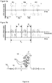
- FIG 3a shows a schematic overview of a mixer output signal and figure 3b of schematic overview of a demodulated signal.
- the mixer output signal comprises several time intervals P1 - P6.
- the amplitude of the signal is small in comparison with the signal in the time intervals P2, P4 and P6. It may be case that this signal is caused by a fluid comprising a liquid such as oil and gas slugs. It is known that gas slugs generate little or no dispersed ultrasound signals and therefore it may be concluded that during the time intervals P1, P3 and P5 the measuring volume was filled with gas slugs, while in the time intervals P2, P4 and P6 the measuring volume was filled with the oil.
- the demodulated signal is a DC-signal. An example of a threshold level is also shown. The splitting or filtering of this signal may then be easily performed by a low-pass filter.
- a flow rate of one of the fluid components in the pipeline for example the flow rate of oil
- the cross section area of the pipeline and the flow velocity of that component are required, but also the fraction of volume of that fluid component with respect to the volume of all fluid components together (i.e. the volume of the fluid).
- the processing unit is arranged to determine the flow rate of a fluid or a fluid component.
- the processing unit 15 may be arranged to determine the flow rate on the basis of this formula.
- the cross section of the pipeline is a constant and known and may be inputted to the processing unit 15.
- the flow velocity of a fluid component may be determined in accordance with one of the embodiments described above.
- the fraction of the fluid component may be determined in several ways, for example based on the weight of a sample of the fluid or other characteristic of that sample. However, it may advantageous to determine the fraction of the fluid component in situ and continuously, since the fraction may vary over time.
- the fraction may be determined on the basis of the time intervals of that fluid component in the receiver signal.
- the sample time interval may be any time interval in which the average fraction is to be determined. It should be at least more than the sum of the durations of the time intervals of the fraction.
- two of the time intervals of a fluid component, for example gas, have been indicated by Ti and Ti+1.
- a sample time interval is indicated by T 0 .
- the processing unit is arranged to determine the fraction on the basis of the above-mentioned formula. Based on the determined fraction of the fluid component, the determined flow velocity of the fluid component, the inputted cross section area of the pipeline, the processing unit 15 may be further arranged to determine the flow rate of the fluid component in fluid comprising at least 2 fluid components.
- a flow velocity of a fluid or a fluid component in a pipeline can be determined by a method comprising the steps of: a) placing a transmitter and a receiver in a pipeline; b) transmitting an ultrasound signal into the fluid or fluid component in a first direction; c) generating a dispersed ultrasound signal in a second direction, by dispersion of the ultrasound signal by the fluid or the fluid component; d) receiving a dispersed ultrasound signal and providing a receiver signal representing the dispersed ultrasound signal; e) determining a frequency difference between the transmitted ultrasound signal and the dispersed ultrasound signal; and, f) determining the flow velocity of the fluid or the fluid component based on said difference.
- FIG 4a an arrangement of a vertical pipe-segment 50 that is preceded by a horizontal section 52, referred to as a horizontal pre-section, is schematically shown.
- the pre-section 52 of the pipe can be used to stabilize the flow and can provide a partial coalescence of a gas phase of the fluid (if present).
- a particular type of such pre-section is a horizontal pipe where natural separation of the flow can occur thanks to gravity force.
- FIG 4a further schematically shows the position of the measurement arrangement 53 in the vertical pipe-segment 50 and the flow direction, indicated by the arrow 54.
- Figure 4b some more details are shown on the horizontal pre-section 52 and the connected pipe 50, showing typical dimensions as a function of the pipe diameter d.
- a single processor or other unit may fulfill the functions of several items recited in the claims.
Landscapes
- Physics & Mathematics (AREA)
- General Physics & Mathematics (AREA)
- Fluid Mechanics (AREA)
- Electromagnetism (AREA)
- Engineering & Computer Science (AREA)
- Aviation & Aerospace Engineering (AREA)
- Measuring Volume Flow (AREA)
- Investigating Or Analyzing Materials By The Use Of Ultrasonic Waves (AREA)
Priority Applications (1)
| Application Number | Priority Date | Filing Date | Title |
|---|---|---|---|
| PL11811411T PL2656019T3 (pl) | 2010-12-21 | 2011-12-20 | Urządzenie i sposób określania prędkości przepływu płynu lub składnika płynu w rurociągu |
Applications Claiming Priority (3)
| Application Number | Priority Date | Filing Date | Title |
|---|---|---|---|
| US201061425704P | 2010-12-21 | 2010-12-21 | |
| NL2005886A NL2005886C2 (en) | 2010-12-21 | 2010-12-21 | Device and method for determining a flow velocity of a fluid or a fluid component in a pipeline. |
| PCT/NL2011/050864 WO2012087120A1 (en) | 2010-12-21 | 2011-12-20 | Device and method for determining a flow velocity of a fluid or a fluid component in a pipeline |
Publications (2)
| Publication Number | Publication Date |
|---|---|
| EP2656019A1 EP2656019A1 (en) | 2013-10-30 |
| EP2656019B1 true EP2656019B1 (en) | 2020-02-05 |
Family
ID=44146376
Family Applications (1)
| Application Number | Title | Priority Date | Filing Date |
|---|---|---|---|
| EP11811411.5A Active EP2656019B1 (en) | 2010-12-21 | 2011-12-20 | Device and method for determining a flow velocity of a fluid or a fluid component in a pipeline |
Country Status (17)
| Country | Link |
|---|---|
| US (1) | US9134158B2 (ko) |
| EP (1) | EP2656019B1 (ko) |
| JP (1) | JP5960721B2 (ko) |
| KR (1) | KR101822423B1 (ko) |
| CN (1) | CN103328934B (ko) |
| BR (1) | BR112013015400A2 (ko) |
| CA (1) | CA2819821C (ko) |
| CY (1) | CY1122894T1 (ko) |
| DK (1) | DK2656019T3 (ko) |
| EA (1) | EA032592B1 (ko) |
| ES (1) | ES2777926T3 (ko) |
| NL (1) | NL2005886C2 (ko) |
| PL (1) | PL2656019T3 (ko) |
| PT (1) | PT2656019T (ko) |
| SG (1) | SG191303A1 (ko) |
| TW (1) | TWI515433B (ko) |
| WO (1) | WO2012087120A1 (ko) |
Families Citing this family (9)
| Publication number | Priority date | Publication date | Assignee | Title |
|---|---|---|---|---|
| EP2913641B1 (en) * | 2014-02-28 | 2019-07-31 | Yokogawa Electric Corporation | Multiphase flowmeter |
| US10422673B2 (en) | 2014-04-01 | 2019-09-24 | Saudi Arabian Oil Company | Flow regime identification of multiphase flows by face recognition Bayesian classification |
| US9424674B2 (en) | 2014-04-01 | 2016-08-23 | Saudi Arabian Oil Company | Tomographic imaging of multiphase flows |
| US9404781B2 (en) | 2014-04-01 | 2016-08-02 | Saudi Arabian Oil Company | Multiphase metering with ultrasonic tomography and vortex shedding |
| US9989387B2 (en) | 2014-04-01 | 2018-06-05 | Saudi Arabian Oil Company | Flow data acquisition and telemetry processing systems |
| US10088347B2 (en) | 2014-04-01 | 2018-10-02 | Saudi Arabian Oil Company | Flow data acquisition and telemetry processing system |
| US9243942B2 (en) | 2014-04-01 | 2016-01-26 | Saudi Arabian Oil Company | Flow line mounting arrangement for flow system transducers |
| DE102014015943B3 (de) | 2014-07-10 | 2015-07-09 | Krohne Ag | Verfahren zum Betreiben eines kernmagnetischen Durchflussmessgeräts |
| FR3063815B1 (fr) * | 2017-03-10 | 2019-03-22 | Sagemcom Energy & Telecom Sas | Procede de mesure d’une vitesse d’un fluide |
Family Cites Families (23)
| Publication number | Priority date | Publication date | Assignee | Title |
|---|---|---|---|---|
| FR1232113A (fr) * | 1958-08-08 | 1960-10-05 | Nat Res Dev | Débitmètres |
| US3165928A (en) * | 1963-02-14 | 1965-01-19 | Poulos Leo | Flow meter |
| US3741014A (en) * | 1970-06-25 | 1973-06-26 | Tokyo Keiki Kk | Ultrasonic current meter |
| US3974500A (en) * | 1975-01-13 | 1976-08-10 | The Singer Company | Velocity sensing apparatus |
| US4066095A (en) | 1976-02-17 | 1978-01-03 | Fred M. Dellorfano, Jr. | Automatic leakage detection system for pipelines carrying fluids |
| JPS5383162U (ko) * | 1976-12-13 | 1978-07-10 | ||
| US4237730A (en) * | 1978-09-15 | 1980-12-09 | Selas Corporation Of America | Fluid velocity measurement system |
| US4181432A (en) * | 1978-10-18 | 1980-01-01 | The Singer Company | Velocity measuring system |
| DE3580670D1 (de) * | 1985-04-17 | 1991-01-03 | Stichting Waterbouwkundig Lab | System zum messen von partikeltransport in fluessigkeit. |
| WO1993009404A1 (en) * | 1991-11-02 | 1993-05-13 | Jordan Kent Metering Systems Limited | Time-of-flight flow measurement with secondary fluid injected as thermal tracer |
| US6209388B1 (en) * | 1996-03-11 | 2001-04-03 | Daniel Industries, Inc. | Ultrasonic 2-phase flow apparatus and method |
| JP4215397B2 (ja) * | 1998-05-14 | 2009-01-28 | ルミネックス コーポレイション | 多重分析物診断システム |
| AU3334800A (en) * | 2000-03-09 | 2001-09-17 | Vladimir Drobkov | Simultaneous determination of multiphase flowrates and concentrations |
| JP4538163B2 (ja) | 2001-03-30 | 2010-09-08 | サーパス工業株式会社 | 流速測定方法及び流速測定装置並びに流量測定方法及び流量測定装置 |
| EP1585944B1 (en) | 2003-01-13 | 2010-09-08 | Expro Meters, Inc. | Apparatus and method using an array of ultrasonic sensors for determining the velocity of a fluid within a pipe |
| US20060048583A1 (en) * | 2004-08-16 | 2006-03-09 | Gysling Daniel L | Total gas meter using speed of sound and velocity measurements |
| NO325703B1 (no) * | 2006-03-16 | 2008-07-07 | Sensorteknikk As | Fremgangsmate for a registrere et strommende mediums karakteristiske tilstand, mengde og sammensetning |
| NO324812B1 (no) * | 2006-05-05 | 2007-12-10 | Multi Phase Meters As | Fremgangsmåte og innretning for tomografiske multifasestrømningsmålinger |
| US7673525B2 (en) * | 2007-01-09 | 2010-03-09 | Schlumberger Technology Corporation | Sensor system for pipe and flow condition monitoring of a pipeline configured for flowing hydrocarbon mixtures |
| DE102007027188A1 (de) | 2007-06-13 | 2008-12-18 | Robert Bosch Gmbh | Ultraschallströmungssensor mit Quadratur-Demodulation |
| US8401805B2 (en) * | 2007-11-15 | 2013-03-19 | National University Corporation Hokkaido University | Ultrasonic multiphase flowmeter, ultrasonic multiphase flow rate measurement program, and multiphase flow rate measurement method using ultrasonic wave |
| EP2103912B1 (de) * | 2008-03-18 | 2016-09-07 | SICK Engineering GmbH | Strömungsmessung mit Ultraschall |
| DE102011079250A1 (de) * | 2011-07-15 | 2013-01-17 | Endress + Hauser Flowtec Ag | Ultraschall-Durchflussmessgerät |
-
2010
- 2010-12-21 NL NL2005886A patent/NL2005886C2/en not_active IP Right Cessation
-
2011
- 2011-12-14 TW TW100146341A patent/TWI515433B/zh active
- 2011-12-20 CA CA2819821A patent/CA2819821C/en active Active
- 2011-12-20 KR KR1020137019160A patent/KR101822423B1/ko active IP Right Grant
- 2011-12-20 WO PCT/NL2011/050864 patent/WO2012087120A1/en active Application Filing
- 2011-12-20 EA EA201390914A patent/EA032592B1/ru unknown
- 2011-12-20 ES ES11811411T patent/ES2777926T3/es active Active
- 2011-12-20 DK DK11811411.5T patent/DK2656019T3/da active
- 2011-12-20 CN CN201180061977.9A patent/CN103328934B/zh active Active
- 2011-12-20 SG SG2013048244A patent/SG191303A1/en unknown
- 2011-12-20 PT PT118114115T patent/PT2656019T/pt unknown
- 2011-12-20 BR BR112013015400A patent/BR112013015400A2/pt not_active IP Right Cessation
- 2011-12-20 EP EP11811411.5A patent/EP2656019B1/en active Active
- 2011-12-20 JP JP2013546053A patent/JP5960721B2/ja active Active
- 2011-12-20 US US13/994,749 patent/US9134158B2/en active Active
- 2011-12-20 PL PL11811411T patent/PL2656019T3/pl unknown
-
2020
- 2020-05-04 CY CY20201100409T patent/CY1122894T1/el unknown
Non-Patent Citations (1)
| Title |
|---|
| None * |
Also Published As
| Publication number | Publication date |
|---|---|
| KR101822423B1 (ko) | 2018-01-26 |
| EA201390914A1 (ru) | 2013-11-29 |
| CN103328934A (zh) | 2013-09-25 |
| US20140290382A1 (en) | 2014-10-02 |
| TW201234014A (en) | 2012-08-16 |
| US9134158B2 (en) | 2015-09-15 |
| JP2014500515A (ja) | 2014-01-09 |
| WO2012087120A1 (en) | 2012-06-28 |
| JP5960721B2 (ja) | 2016-08-02 |
| BR112013015400A2 (pt) | 2017-12-05 |
| ES2777926T3 (es) | 2020-08-06 |
| KR20140022789A (ko) | 2014-02-25 |
| NL2005886C2 (en) | 2012-06-25 |
| PL2656019T3 (pl) | 2020-08-10 |
| PT2656019T (pt) | 2020-04-22 |
| CY1122894T1 (el) | 2021-05-05 |
| CN103328934B (zh) | 2016-08-17 |
| TWI515433B (zh) | 2016-01-01 |
| CA2819821A1 (en) | 2012-06-28 |
| DK2656019T3 (da) | 2020-04-20 |
| EP2656019A1 (en) | 2013-10-30 |
| EA032592B1 (ru) | 2019-06-28 |
| CA2819821C (en) | 2019-04-23 |
| SG191303A1 (en) | 2013-07-31 |
Similar Documents
| Publication | Publication Date | Title |
|---|---|---|
| EP2656019B1 (en) | Device and method for determining a flow velocity of a fluid or a fluid component in a pipeline | |
| JP4800543B2 (ja) | 多相液体/気体混合物の流量及び濃度を同時に測定する方法及び装置 | |
| US8694270B2 (en) | Ultrasonic clamp-on multiphase flowmeter | |
| US10088590B2 (en) | Methods for measuring properties of multiphase oil-water-gas mixtures | |
| US10908131B2 (en) | Acoustic gas volume fraction measurement in a multiphase flowing liquid | |
| US20190154479A1 (en) | Estimating flow velocity in pipes by correlating multi-frequency signals | |
| CA2279257A1 (en) | An ultrasonic flow velocity measuring method | |
| US11525719B2 (en) | Estimating flow velocity by harmonic excitation of injected microbubbles | |
| Coulthard et al. | Ultrasonic cross-correlation flowmeters | |
| JP5946025B2 (ja) | 多相流流量計 | |
| Decrop et al. | New methods for ADV measurements of turbulent sediment fluxes–application to a fine sediment plume | |
| Waluś | Mathematical modelling of an ultrasonic flowmeter primary device | |
| Goncalves et al. | Development of a multiphase flow metering procedure based on the ultrasonic technique | |
| JP2632041B2 (ja) | 流速計 | |
| JP5924556B2 (ja) | 多相流流量計 | |
| Clunie et al. | Flow measurement using flying ADV probes | |
| Drenthen | Acoustic discharge measuring devices | |
| RU2430381C2 (ru) | Способ определения скорости потока и расхода жидких и газообразных продуктов | |
| JP2017215188A (ja) | 流速分布の計測方法及びその装置 | |
| SA08290690B1 (ar) | قياس تدفق متعدد الأطوار |
Legal Events
| Date | Code | Title | Description |
|---|---|---|---|
| PUAI | Public reference made under article 153(3) epc to a published international application that has entered the european phase |
Free format text: ORIGINAL CODE: 0009012 |
|
| 17P | Request for examination filed |
Effective date: 20130715 |
|
| AK | Designated contracting states |
Kind code of ref document: A1 Designated state(s): AL AT BE BG CH CY CZ DE DK EE ES FI FR GB GR HR HU IE IS IT LI LT LU LV MC MK MT NL NO PL PT RO RS SE SI SK SM TR |
|
| DAX | Request for extension of the european patent (deleted) | ||
| RAP1 | Party data changed (applicant data changed or rights of an application transferred) |
Owner name: SHUSTOV, ANDREY |
|
| RIN1 | Information on inventor provided before grant (corrected) |
Inventor name: MELNIKOV, VLADIMIR Inventor name: DROBKOV, VLADIMIR Inventor name: SHUSTOV, ANDREY |
|
| STAA | Information on the status of an ep patent application or granted ep patent |
Free format text: STATUS: EXAMINATION IS IN PROGRESS |
|
| 17Q | First examination report despatched |
Effective date: 20181116 |
|
| GRAP | Despatch of communication of intention to grant a patent |
Free format text: ORIGINAL CODE: EPIDOSNIGR1 |
|
| STAA | Information on the status of an ep patent application or granted ep patent |
Free format text: STATUS: GRANT OF PATENT IS INTENDED |
|
| INTG | Intention to grant announced |
Effective date: 20190924 |
|
| RIN1 | Information on inventor provided before grant (corrected) |
Inventor name: SHUSTOV, ANDREY Inventor name: DROBKOV, VLADIMIR Inventor name: MELNIKOV, VLADIMIR |
|
| GRAS | Grant fee paid |
Free format text: ORIGINAL CODE: EPIDOSNIGR3 |
|
| GRAA | (expected) grant |
Free format text: ORIGINAL CODE: 0009210 |
|
| STAA | Information on the status of an ep patent application or granted ep patent |
Free format text: STATUS: THE PATENT HAS BEEN GRANTED |
|
| AK | Designated contracting states |
Kind code of ref document: B1 Designated state(s): AL AT BE BG CH CY CZ DE DK EE ES FI FR GB GR HR HU IE IS IT LI LT LU LV MC MK MT NL NO PL PT RO RS SE SI SK SM TR |
|
| REG | Reference to a national code |
Ref country code: GB Ref legal event code: FG4D |
|
| REG | Reference to a national code |
Ref country code: AT Ref legal event code: REF Ref document number: 1230244 Country of ref document: AT Kind code of ref document: T Effective date: 20200215 |
|
| REG | Reference to a national code |
Ref country code: DE Ref legal event code: R096 Ref document number: 602011064852 Country of ref document: DE |
|
| REG | Reference to a national code |
Ref country code: IE Ref legal event code: FG4D |
|
| REG | Reference to a national code |
Ref country code: CH Ref legal event code: EP |
|
| REG | Reference to a national code |
Ref country code: CH Ref legal event code: NV Representative=s name: ISLER AND PEDRAZZINI AG, CH Ref country code: RO Ref legal event code: EPE |
|
| REG | Reference to a national code |
Ref country code: DK Ref legal event code: T3 Effective date: 20200417 |
|
| REG | Reference to a national code |
Ref country code: FI Ref legal event code: FGE |
|
| REG | Reference to a national code |
Ref country code: NL Ref legal event code: FP Ref country code: PT Ref legal event code: SC4A Ref document number: 2656019 Country of ref document: PT Date of ref document: 20200422 Kind code of ref document: T Free format text: AVAILABILITY OF NATIONAL TRANSLATION Effective date: 20200413 |
|
| REG | Reference to a national code |
Ref country code: SE Ref legal event code: TRGR |
|
| REG | Reference to a national code |
Ref country code: NO Ref legal event code: T2 Effective date: 20200205 |
|
| REG | Reference to a national code |
Ref country code: SK Ref legal event code: T3 Ref document number: E 33902 Country of ref document: SK |
|
| REG | Reference to a national code |
Ref country code: GR Ref legal event code: EP Ref document number: 20200401212 Country of ref document: GR Effective date: 20200716 |
|
| PG25 | Lapsed in a contracting state [announced via postgrant information from national office to epo] |
Ref country code: RS Free format text: LAPSE BECAUSE OF FAILURE TO SUBMIT A TRANSLATION OF THE DESCRIPTION OR TO PAY THE FEE WITHIN THE PRESCRIBED TIME-LIMIT Effective date: 20200205 |
|
| REG | Reference to a national code |
Ref country code: ES Ref legal event code: FG2A Ref document number: 2777926 Country of ref document: ES Kind code of ref document: T3 Effective date: 20200806 |
|
| REG | Reference to a national code |
Ref country code: LT Ref legal event code: MG4D |
|
| PG25 | Lapsed in a contracting state [announced via postgrant information from national office to epo] |
Ref country code: HR Free format text: LAPSE BECAUSE OF FAILURE TO SUBMIT A TRANSLATION OF THE DESCRIPTION OR TO PAY THE FEE WITHIN THE PRESCRIBED TIME-LIMIT Effective date: 20200205 Ref country code: LV Free format text: LAPSE BECAUSE OF FAILURE TO SUBMIT A TRANSLATION OF THE DESCRIPTION OR TO PAY THE FEE WITHIN THE PRESCRIBED TIME-LIMIT Effective date: 20200205 Ref country code: IS Free format text: LAPSE BECAUSE OF FAILURE TO SUBMIT A TRANSLATION OF THE DESCRIPTION OR TO PAY THE FEE WITHIN THE PRESCRIBED TIME-LIMIT Effective date: 20200605 Ref country code: BG Free format text: LAPSE BECAUSE OF FAILURE TO SUBMIT A TRANSLATION OF THE DESCRIPTION OR TO PAY THE FEE WITHIN THE PRESCRIBED TIME-LIMIT Effective date: 20200505 |
|
| PG25 | Lapsed in a contracting state [announced via postgrant information from national office to epo] |
Ref country code: LT Free format text: LAPSE BECAUSE OF FAILURE TO SUBMIT A TRANSLATION OF THE DESCRIPTION OR TO PAY THE FEE WITHIN THE PRESCRIBED TIME-LIMIT Effective date: 20200205 Ref country code: EE Free format text: LAPSE BECAUSE OF FAILURE TO SUBMIT A TRANSLATION OF THE DESCRIPTION OR TO PAY THE FEE WITHIN THE PRESCRIBED TIME-LIMIT Effective date: 20200205 Ref country code: SM Free format text: LAPSE BECAUSE OF FAILURE TO SUBMIT A TRANSLATION OF THE DESCRIPTION OR TO PAY THE FEE WITHIN THE PRESCRIBED TIME-LIMIT Effective date: 20200205 |
|
| REG | Reference to a national code |
Ref country code: DE Ref legal event code: R097 Ref document number: 602011064852 Country of ref document: DE |
|
| REG | Reference to a national code |
Ref country code: AT Ref legal event code: UEP Ref document number: 1230244 Country of ref document: AT Kind code of ref document: T Effective date: 20200205 |
|
| PLBE | No opposition filed within time limit |
Free format text: ORIGINAL CODE: 0009261 |
|
| STAA | Information on the status of an ep patent application or granted ep patent |
Free format text: STATUS: NO OPPOSITION FILED WITHIN TIME LIMIT |
|
| 26N | No opposition filed |
Effective date: 20201106 |
|
| PG25 | Lapsed in a contracting state [announced via postgrant information from national office to epo] |
Ref country code: SI Free format text: LAPSE BECAUSE OF FAILURE TO SUBMIT A TRANSLATION OF THE DESCRIPTION OR TO PAY THE FEE WITHIN THE PRESCRIBED TIME-LIMIT Effective date: 20200205 |
|
| PGFP | Annual fee paid to national office [announced via postgrant information from national office to epo] |
Ref country code: MC Payment date: 20211217 Year of fee payment: 11 Ref country code: FI Payment date: 20211216 Year of fee payment: 11 |
|
| PGFP | Annual fee paid to national office [announced via postgrant information from national office to epo] |
Ref country code: GR Payment date: 20211217 Year of fee payment: 11 |
|
| PGFP | Annual fee paid to national office [announced via postgrant information from national office to epo] |
Ref country code: PL Payment date: 20211210 Year of fee payment: 11 Ref country code: MT Payment date: 20211222 Year of fee payment: 11 |
|
| PGFP | Annual fee paid to national office [announced via postgrant information from national office to epo] |
Ref country code: ES Payment date: 20220322 Year of fee payment: 11 |
|
| PG25 | Lapsed in a contracting state [announced via postgrant information from national office to epo] |
Ref country code: MK Free format text: LAPSE BECAUSE OF FAILURE TO SUBMIT A TRANSLATION OF THE DESCRIPTION OR TO PAY THE FEE WITHIN THE PRESCRIBED TIME-LIMIT Effective date: 20200205 Ref country code: AL Free format text: LAPSE BECAUSE OF FAILURE TO SUBMIT A TRANSLATION OF THE DESCRIPTION OR TO PAY THE FEE WITHIN THE PRESCRIBED TIME-LIMIT Effective date: 20200205 |
|
| PGFP | Annual fee paid to national office [announced via postgrant information from national office to epo] |
Ref country code: SK Payment date: 20221207 Year of fee payment: 12 Ref country code: SE Payment date: 20221220 Year of fee payment: 12 Ref country code: RO Payment date: 20221213 Year of fee payment: 12 Ref country code: LU Payment date: 20221227 Year of fee payment: 12 Ref country code: IE Payment date: 20221219 Year of fee payment: 12 Ref country code: CZ Payment date: 20221208 Year of fee payment: 12 Ref country code: AT Payment date: 20221222 Year of fee payment: 12 |
|
| PGFP | Annual fee paid to national office [announced via postgrant information from national office to epo] |
Ref country code: PT Payment date: 20221216 Year of fee payment: 12 |
|
| PGFP | Annual fee paid to national office [announced via postgrant information from national office to epo] |
Ref country code: TR Payment date: 20221219 Year of fee payment: 12 |
|
| PGFP | Annual fee paid to national office [announced via postgrant information from national office to epo] |
Ref country code: IT Payment date: 20221221 Year of fee payment: 12 Ref country code: CY Payment date: 20221213 Year of fee payment: 12 |
|
| PG25 | Lapsed in a contracting state [announced via postgrant information from national office to epo] |
Ref country code: GR Free format text: LAPSE BECAUSE OF NON-PAYMENT OF DUE FEES Effective date: 20230705 |
|
| PGFP | Annual fee paid to national office [announced via postgrant information from national office to epo] |
Ref country code: GB Payment date: 20231220 Year of fee payment: 13 |
|
| PGFP | Annual fee paid to national office [announced via postgrant information from national office to epo] |
Ref country code: NO Payment date: 20231218 Year of fee payment: 13 Ref country code: NL Payment date: 20231221 Year of fee payment: 13 Ref country code: FR Payment date: 20231219 Year of fee payment: 13 Ref country code: DK Payment date: 20231219 Year of fee payment: 13 Ref country code: DE Payment date: 20231214 Year of fee payment: 13 |
|
| REG | Reference to a national code |
Ref country code: ES Ref legal event code: FD2A Effective date: 20240202 |
|
| PGFP | Annual fee paid to national office [announced via postgrant information from national office to epo] |
Ref country code: BE Payment date: 20231219 Year of fee payment: 13 |
|
| PG25 | Lapsed in a contracting state [announced via postgrant information from national office to epo] |
Ref country code: ES Free format text: LAPSE BECAUSE OF NON-PAYMENT OF DUE FEES Effective date: 20221221 |
|
| PG25 | Lapsed in a contracting state [announced via postgrant information from national office to epo] |
Ref country code: FI Free format text: LAPSE BECAUSE OF NON-PAYMENT OF DUE FEES Effective date: 20221220 Ref country code: ES Free format text: LAPSE BECAUSE OF NON-PAYMENT OF DUE FEES Effective date: 20221221 |
|
| PGFP | Annual fee paid to national office [announced via postgrant information from national office to epo] |
Ref country code: CH Payment date: 20240110 Year of fee payment: 13 |