EP2655921B1 - Centrifugal pendulum mechanism - Google Patents
Centrifugal pendulum mechanism Download PDFInfo
- Publication number
- EP2655921B1 EP2655921B1 EP11815679.3A EP11815679A EP2655921B1 EP 2655921 B1 EP2655921 B1 EP 2655921B1 EP 11815679 A EP11815679 A EP 11815679A EP 2655921 B1 EP2655921 B1 EP 2655921B1
- Authority
- EP
- European Patent Office
- Prior art keywords
- pendulum
- pendulum mass
- spring
- stop element
- masses
- Prior art date
- Legal status (The legal status is an assumption and is not a legal conclusion. Google has not performed a legal analysis and makes no representation as to the accuracy of the status listed.)
- Active
Links
Images


Classifications
-
- F—MECHANICAL ENGINEERING; LIGHTING; HEATING; WEAPONS; BLASTING
- F16—ENGINEERING ELEMENTS AND UNITS; GENERAL MEASURES FOR PRODUCING AND MAINTAINING EFFECTIVE FUNCTIONING OF MACHINES OR INSTALLATIONS; THERMAL INSULATION IN GENERAL
- F16F—SPRINGS; SHOCK-ABSORBERS; MEANS FOR DAMPING VIBRATION
- F16F15/00—Suppression of vibrations in systems; Means or arrangements for avoiding or reducing out-of-balance forces, e.g. due to motion
- F16F15/10—Suppression of vibrations in rotating systems by making use of members moving with the system
- F16F15/12—Suppression of vibrations in rotating systems by making use of members moving with the system using elastic members or friction-damping members, e.g. between a rotating shaft and a gyratory mass mounted thereon
- F16F15/121—Suppression of vibrations in rotating systems by making use of members moving with the system using elastic members or friction-damping members, e.g. between a rotating shaft and a gyratory mass mounted thereon using springs as elastic members, e.g. metallic springs
- F16F15/1214—Folded springs, i.e. made of band-like material folded in an enclosing space
-
- F—MECHANICAL ENGINEERING; LIGHTING; HEATING; WEAPONS; BLASTING
- F16—ENGINEERING ELEMENTS AND UNITS; GENERAL MEASURES FOR PRODUCING AND MAINTAINING EFFECTIVE FUNCTIONING OF MACHINES OR INSTALLATIONS; THERMAL INSULATION IN GENERAL
- F16F—SPRINGS; SHOCK-ABSORBERS; MEANS FOR DAMPING VIBRATION
- F16F15/00—Suppression of vibrations in systems; Means or arrangements for avoiding or reducing out-of-balance forces, e.g. due to motion
- F16F15/10—Suppression of vibrations in rotating systems by making use of members moving with the system
- F16F15/14—Suppression of vibrations in rotating systems by making use of members moving with the system using masses freely rotating with the system, i.e. uninvolved in transmitting driveline torque, e.g. rotative dynamic dampers
- F16F15/1407—Suppression of vibrations in rotating systems by making use of members moving with the system using masses freely rotating with the system, i.e. uninvolved in transmitting driveline torque, e.g. rotative dynamic dampers the rotation being limited with respect to the driving means
- F16F15/145—Masses mounted with play with respect to driving means thus enabling free movement over a limited range
-
- Y—GENERAL TAGGING OF NEW TECHNOLOGICAL DEVELOPMENTS; GENERAL TAGGING OF CROSS-SECTIONAL TECHNOLOGIES SPANNING OVER SEVERAL SECTIONS OF THE IPC; TECHNICAL SUBJECTS COVERED BY FORMER USPC CROSS-REFERENCE ART COLLECTIONS [XRACs] AND DIGESTS
- Y10—TECHNICAL SUBJECTS COVERED BY FORMER USPC
- Y10T—TECHNICAL SUBJECTS COVERED BY FORMER US CLASSIFICATION
- Y10T74/00—Machine element or mechanism
- Y10T74/21—Elements
- Y10T74/2121—Flywheel, motion smoothing-type
- Y10T74/2128—Damping using swinging masses, e.g., pendulum type, etc.
Landscapes
- Engineering & Computer Science (AREA)
- General Engineering & Computer Science (AREA)
- Physics & Mathematics (AREA)
- Acoustics & Sound (AREA)
- Aviation & Aerospace Engineering (AREA)
- Mechanical Engineering (AREA)
- Mechanical Operated Clutches (AREA)
- Vibration Prevention Devices (AREA)
- One-Way And Automatic Clutches, And Combinations Of Different Clutches (AREA)
Description
Die vorliegende Erfindung betrifft eine Fliehkraftpendeleinrichtung, insbesondere eine Trapezfliehkraftpendeleinrichtung, für eine Dämpfereinrichtung und/oder eine Drehmomentübertragungseinrichtung, insbesondere für einen Antriebsstrang eines Kraftfahrzeugs. Ferner betrifft die Erfindung eine Dämpfereinrichtung oder eine Drehmomentübertragungseinrichtung insbesondere für einen Antriebsstrang eines Kraftfahrzeugs; z. B. ein Fliehkraftpendel, einen Drehmomentwandler, eine Kupplung, eine Föttingerkupplung, eine Kupplungsbaugruppe, einen Dämpfer, einen Drehschwingungsdämpfer, einen Turbinendämpfer, einen Pumpendämpfer, einen Zweimassenwandler oder ein Zweimassenschwungrad, oder Kombinationen davon; wobei die die Dämpfereinrichtung bzw. die Drehmomentübertragungseinrichtung eine erfindungsgemäße Fliehkraftpendeleinrichtung aufweist.The present invention relates to a centrifugal pendulum device, in particular a trapezoidal centrifugal pendulum device, for a damper device and / or a torque transmission device, in particular for a drive train of a motor vehicle. Furthermore, the invention relates to a damper device or a torque transmission device, in particular for a drive train of a motor vehicle; z. A centrifugal pendulum, a torque converter, a clutch, a Föttingerkupplung, a clutch assembly, a damper, a torsional vibration damper, a turbine damper, a pump damper, a two-mass converter or a dual-mass flywheel, or combinations thereof; wherein the damper device or the torque transfer device comprises a centrifugal pendulum device according to the invention.
An Wellen von periodisch arbeitenden Maschinen, z. B. an einer Kurbelwelle eines Verbrennungsmotors eines Kraftfahrzeugs, treten bei einer Rotationsbewegung der Welle überlagernde Drehschwingungen auf, wobei sich deren Frequenz mit einer Drehzahl der Welle ändert. Durch Verbrennungsvorgänge des Verbrennungsmotors werden insbesondere im Zugbetrieb Drehschwingungen im Antriebsstrang des Kraftfahrzeugs angeregt. Zur Verringerung dieser Drehschwingungen kann ein Fliehkraftpendel vorgesehen sein, das Drehschwingungen über einen größeren Drehzahlbereich des Verbrennungsmotors, idealerweise über dessen gesamten Drehzahlbereich hinweg, tilgen kann. Den Fliehkraftpendeln liegt das Prinzip zugrunde, dass deren Pendelmassen fliehkraftbedingt bestrebt sind, eine Rotationsachse bei Einleitung einer Drehbewegung in größtmöglichem Abstand zu umkreisen. Die Drehschwingungen in der Welle führen zu einer pendelnden Relativbewegung der Pendelmassen, wobei das Fliehkraftpendel eine zur Drehzahl proportionale Eigenfrequenz besitzt, so dass Drehschwingungen mit Frequenzen, die der Drehzahl der Welle in gleicher Weise proportional sind, über einen großen Drehzahlbereich hinweg tilgbar sind.At waves of periodically operating machines, eg. B. on a crankshaft of an internal combustion engine of a motor vehicle, occur in a rotational movement of the shaft superimposed torsional vibrations, wherein the frequency changes with a speed of the shaft. By combustion processes of the internal combustion engine torsional vibrations in the drive train of the motor vehicle are excited in particular in the train operation. To reduce these torsional vibrations, a centrifugal pendulum can be provided, which can eliminate torsional vibrations over a larger speed range of the internal combustion engine, ideally over its entire speed range. The centrifugal pendulum pendulum is based on the principle that their pendulum masses are endeavored by centrifugal force to orbit a rotation axis at initiation of a rotational movement in the greatest possible distance. The torsional vibrations in the shaft lead to a pendulum relative movement of the pendulum masses, wherein the centrifugal pendulum has a natural frequency proportional to the rotational speed, so that torsional vibrations with frequencies that are proportional to the rotational speed of the shaft in the same way, are tilgbar over a large speed range.
Ein Fliehkraftpendel umfasst eine Mehrzahl von Pendelmassen, die mittels Führungselementen an einem rotierenden Pendelmassenträger aufgehängt sind und entlang vorgegebener Führungsbahnen eine Relativbewegung zu diesem Pendelmassenträger ausführen können, um hierbei einen variablen Abstand zur Rotationsachse des Pendelmassenträgers einnehmen zu können. Als eine Folge der Drehschwingungen im Antriebsstrang werden die Pendelmassen zum Pendeln bzw. Schwingen angeregt, wobei sich deren Schwerpunkte permanent und zeitversetzt zu den Drehschwingungen im Antriebsstrang verändern, was durch eine mechanische Rückkopplung eine Dämpfung der Drehschwingungen bewirkt. Eine effiziente Dämpfung kann durch entsprechende Abstimmung der Pendelmassen und deren Führungsbahnen erfolgen. - In bestimmten Betriebszuständen des Fliehkraftpendels kann es zu einem Anstoßen der Pendelmassen an den Pendelmassenträger, einem Aneinanderstoßen der in Umfangsrichtung benachbarten Stirnseiten der Pendelmassen und/oder einem Anstoßen der Führungselemente in den betreffenden Längsenden der Führungsbahnen des Pendelmassenträgers und/oder der Pendelmassen kommen, wodurch Funktionsstörungen des Fliehkraftpendels und Geräusche hervorgerufen werden, was zu einem subjektiv wahrnehmbaren Verlust an Fahr- und Geräuschkomfort führt.A centrifugal pendulum comprises a plurality of pendulum masses, which are suspended by means of guide elements on a rotating pendulum mass carrier and along predetermined guideways can perform a relative movement to this pendulum mass carrier to occupy a variable distance from the axis of rotation of the pendulum mass carrier to be able to. As a result of the torsional vibrations in the drive train pendulum masses are excited to oscillate or oscillate, with their focal points permanently and time-shifted change to the torsional vibrations in the drive train, which causes a damping of torsional vibrations by a mechanical feedback. An efficient damping can be done by appropriate coordination of the pendulum masses and their tracks. - In certain operating conditions of the centrifugal pendulum mass, it may lead to an abutment of the pendulum masses of the pendulum mass carrier, a collision of adjacent circumferentially end faces of the pendulum masses and / or abutment of the guide elements in the respective longitudinal ends of the guideways of the pendulum mass carrier and / or pendulum masses, causing malfunction of the centrifugal pendulum and noises are caused, resulting in a subjectively perceivable loss of driving and noise comfort.
Das Unterbringen der Pendelmassen mit einem entsprechenden Sicherheitsabstand in Umfangsrichtung zueinander führt zu einer unerwünschten Verringerung der Pendelmassen und/ oder das Begrenzen der Schwingwinkel führt zu einem Verlust einer Effektivität des Fliehkraftpendels. Ferner ist die Anwendung von Gummielementen unter Aspekten der Wärmedehnung und Verformung unter Krafteinwirkung hinsichtlich Toleranz schlecht berechenbar. Eine Zuverlässigkeit und eine Lebensdauer von Gummielementen in einer Ölumgebung stellt sich als problematisch dar. Ferner verhindern Gummielemente Zusammenstöße zwischen in Umfangsrichtung benachbarten Pendelmassen nicht, sondern nur zwischen Pendelmassen und dem Pendelmassenträger. Des Weiteren sind Anschlagelemente bei Fliehkraftpendeln mit Trapezanordnung der Pendelmassen nur bedingt einsetzbar.The accommodation of the pendulum masses with a corresponding safety distance in the circumferential direction to each other leads to an undesirable reduction of pendulum masses and / or limiting the swing angle leads to a loss of effectiveness of the centrifugal pendulum. Furthermore, the application of rubber members under aspects of thermal expansion and deformation under force is poorly predictable in terms of tolerance. A reliability and a life of rubber elements in an oil environment is problematic. Furthermore, rubber elements do not prevent collisions between circumferentially adjacent pendulum masses, but only between pendulum masses and the pendulum mass carrier. Furthermore, stop elements in centrifugal pendulum with trapezoidal arrangement of the pendulum masses are only limited use.
Die
Es ist eine Aufgabe der Erfindung, eine verbesserte Fliehkraftpendeleinrichtung für eine Dämpfereinrichtung und/oder eine Drehmomentübertragungseinrichtung, insbesondere für einen Antriebsstrang eines Kraftfahrzeugs, anzugeben. Ferner ist es eine Aufgabe der Erfindung eine verbesserte Dämpfereinrichtung und/oder eine verbesserte Drehmomentübertragungseinrichtung insbesondere für einen Antriebsstrang eines Kraftfahrzeugs, zur Verfügung zu stellen. Hierbei soll die erfindungsgemäße Fliehkraftpendeleinrichtung bzw. ein mit der erfindungsgemäßen Fliehkraftpendeleinrichtung ausgerüstetes Fliehkraftpendel geringe Geräuschemissionen aufweisen. Ferner sollen Funktionsstörungen der Fliehkraftpendeleinrichtung, die aufgrund unkontrollierter Bewegungen der Pendelmassen hervorgerufenen werden verringert sein. Hierbei soll insbesondere ein Anstoßen der Pendelmassen an den Pendelmassenträger, ein Aneinanderstoßen der in Umfangsrichtung benachbarten Stirnseiten der Pendelmassen und/oder ein Anstoßen der Führungselemente in den betreffenden Längsenden der Führungsbahnen des Pendelmassenträgers und/oder der Pendelmassen verringert sein.
Die Aufgabe der Erfindung wird mittels einer Fliehkraftpendeleinrichtung, insbesondere einer Trapezfliehkraftpendeleinrichtung, für eine Dämpfereinrichtung und/oder eine Drehmomentübertragungseinrichtung, insbesondere für einen Antriebsstrang eines Kraftfahrzeugs, gemäß Anspruch 1; und mittels einer Dämpfereinrichtung oder einer Drehmomentübertragungseinrichtung, bevorzugt für einen Antriebsstrang eines Kraftfahrzeugs; z. B. ein Fliehkraftpendel, einen Drehmomentwandler, eine Kupplung, eine Föttingerkupplung, eine Kupplungsbaugruppe, einen Dämpfer, einen Drehschwingungsdämpfer, einen Turbinendämpfer, einen Pumpendämpfer, einen Zweimassenwandler oder ein Zweimassenschwungrad, oder Kombinationen davon; gemäß Anspruch 6 gelöst. Vorteilhafte Weiterbildungen der Erfindung ergeben sich aus den jeweils abhängigen Ansprüchen.
Die erfindungsgemäße Fliehkraftpendeleinrichtung weist einen um eine Rotationsachse rotierbaren Pendelmassenträger auf, an welchem in Umfangsrichtung eine Mehrzahl gegenüber dem Pendelmassenträger bewegbare Pendelmassen oder Pendelmassenpaare vorgesehen sind. Gemäß der Erfindung sind zwei in Umfangsrichtung des Pendelmassenträgers direkt benachbarte Pendelmassen oder Pendelmassenpaare über ein erfindungsgemäßes Dämpferelement miteinander mechanisch gekoppelt oder mechanisch koppelbar. Bevorzugt ist die Erfindung bei Fliehkraftpendeln mit Trapezanordnung und einem regulierbaren Tilgungsordnungsverlauf für eine Stoßdämpfung und für eine Verhinderung von Klappergeräuschen einsetzbar. - Nachfolgend ist nur noch von einem jeweiligen oder betreffenden Pendelmassenpaar bzw. -paaren die Rede; das nachfolgend Gesagte soll jedoch auch auf jeweilige bzw. betreffende (einzelne) Pendelmassen zutreffen. In einem solchen Fall entfällt lediglich ein zweiter Axialbereich der Fliehkraftpendeleinrichtung, der zu einem ersten Axialbereich symmetrisch aufgebaut ist; d. h. im Fall von Pendelmassenpaaren sind die beiden Axialbereiche ähnlich oder im Wesentlichen identisch konfiguriert und lediglich durch den Pendelmassenträger voneinander getrennt. Ferner können die jeweiligen Ausführungsformen der nachfolgend beschriebenen ersten und zweiten Variante des erfindungsgemäßen Dämpferelements auch unabhängig von der erfindungsgemäßen Fliehkraftpendeleinrichtung sein.It is an object of the invention to provide an improved centrifugal pendulum device for a damper device and / or a torque transmission device, in particular for a drive train of a motor vehicle. Furthermore, it is an object of the invention to provide an improved damper device and / or an improved torque transmission device, in particular for a drive train of a motor vehicle. Here, the centrifugal pendulum device according to the invention or equipped with the centrifugal pendulum device according to the invention centrifugal pendulum should have low noise emissions. Furthermore, malfunction of the centrifugal pendulum device, which are caused due to uncontrolled movements of the pendulum masses to be reduced. In this case, in particular an abutment of the pendulum masses to the pendulum mass carrier, adjacent to each other in the circumferential direction end faces of the pendulum masses and / or abutment of the guide elements in the respective longitudinal ends of the guideways of the pendulum mass carrier and / or pendulum masses should be reduced.
The object of the invention is by means of a centrifugal pendulum device, in particular a trapezoidal centrifugal pendulum device, for a damper device and / or a torque transmission device, in particular for a drive train of a motor vehicle, according to
The centrifugal pendulum device according to the invention has a pendulum mass carrier which is rotatable about an axis of rotation and on which a plurality of pendulum masses or pendulum mass pairs movable relative to the pendulum mass carrier are provided in the circumferential direction. According to the invention, two are direct in the circumferential direction of the pendulum mass carrier adjacent pendulum masses or pendulum mass pairs via a damper element according to the invention with each other mechanically coupled or mechanically coupled. Preferably, the invention in centrifugal pendulum with trapezoidal arrangement and a regulatory repayment order history for shock absorption and for the prevention of rattling noises can be used. - Below is only of a respective or respective pendulum mass pair or pairs the speech; However, what is said below should also apply to respective or relevant (individual) pendulum masses. In such a case, only a second axial region of the centrifugal pendulum device, which is constructed symmetrically to a first axial region, is eliminated; ie in the case of pendulum mass pairs, the two axial areas are similar or substantially identically configured and separated only by the pendulum mass carrier. Furthermore, the respective embodiments of the first and second variants of the damper element according to the invention described below can also be independent of the centrifugal pendulum device according to the invention.
In einem nicht erfindungsgemäßen Beispiel ist das Dämpferelement zwischen den zwei direkt benachbarten, d. h. betreffenden oder jeweiligen, Pendelmassenpaaren als ein Federelement ausgebildet, das diese Pendelmassenpaare mechanisch miteinander verbindet. Hierbei kann das Federelement bei bestimmten Relativbewegungen zwischen den betreffenden Pendelmassenpaaren federweich und bei bestimmten anderen Relativbewegungen zwischen den betreffenden Pendelmassenpaaren federhart ausgebildet sein, d. h. in bestimmten Bereichen ist das Federelement federweich und in bestimmten Bereichen ist das Federelement federhart ausgebildet, wobei diese Bereiche voneinander getrennt oder einander überlappend im Federelement vorgesehen sein können. Das Federelement kann dabei in Radialrichtung der Fliehkraftpendeleinrichtung federweich, insbesondere in Umfangsrichtung abgesehen von einem Federbereich ebenfalls federweich, bevorzugt in einer Axialrichtung federhart und insbesondere bevorzugt im Federbereich ebenfalls federhart ausgebildet sein.-Durch das, abgesehen vom Federbereich, in Radial- und in Umfangsrichtung elastisch ausgestaltete Federelement kann ein Nachgeben in diesen Richtungen während einer Schwingung der Pendelmassen ohne nennenswerten Widerstand erfolgen. Ein Abfedern der betreffenden Pendelmassenpaare gegeneinander erfolgt z. B. erst beim Zusammenklappen der betreffenden Pendelmassenpaare; d. h. wenn das Federelement mit einer Federseite im Wesentlich vollständig an einem Pendelmassenpaar anliegt und sich das andere Pendelmassenpaar auf das erste zubewegt.In a non-inventive example, the damper element between the two directly adjacent, ie relevant or respective pendulum mass pairs is designed as a spring element which mechanically connects these pendulum mass pairs together. Here, the spring element in certain relative movements between the respective pendulum masses spring soft and certain other relative movements between the respective pendulum masses be spring-hard, ie in certain areas, the spring element is feather soft and in certain areas, the spring element is spring-hard, these areas separated from each other or each other may be provided overlapping in the spring element. The spring element can be spring soft in the radial direction of the centrifugal pendulum pendulum device, especially in the circumferential direction apart from a spring range also feather soft, preferably in an axial spring-hard and particularly preferably spring-trained in the spring. -By, apart from the spring range, in the radial and circumferential direction elastic designed spring element can give way in these directions during oscillation of the pendulum masses without significant resistance. A cushioning of the respective pendulum mass pairs against each other z. B. only when folding the respective pendulum mass pairs; that is, when the spring element with a spring side substantially completely rests on a pendulum mass pair and moves the other pendulum mass pair to the first.
Bevorzugt sind alle Pendelmassenpaare des Pendelmassenträgers mittels Federelementen ringförmig zu einem Verbund zusammen geschlossen. Hierbei sollte eine Einstellung der Federelemente symmetrisch sein, damit sich keine Schwerpunktsverschiebung der Pendelmassenpaare und Verkippmomente an den Pendelmassenpaaren ergeben. Insbesondere durch eine in Axialrichtung federharte Ausbildung der Federelemente sind Anschläge der Pendelmassenpaare an dem Pendelmassenträger wirksam verhindert. Ferner werden Zusammenstöße der betreffenden Pendelmassen bei maximaler Auslenkung und in Übergangsphasen im Betrieb des Fliehkraftpendels durch die bevorzugt als Blechfedern ausgebildeten Federelemente wirksam verhindert. - In bevorzugten Ausführungsformen des nicht erfindungsgemäßen Beispiels ist das Federelement als eine Lamellen- oder eine Streifenfeder ausgebildet, die die betreffenden Pendelmassenpaare miteinander mechanisch verbindet, wobei diese Pendelmassenpaare in Abhängigkeit einer gegenseitigen Position gegeneinander federnd vorsehbar sind. Bevorzugt ist jeweils ein Befestigungsbereich der Lamellenfeder an einem betreffenden Pendelmassenpaar festgelegt, wobei sich zwischen den beiden Befestigungsbereichen zwischen den betreffenden Pendelmassenpaaren der Federbereich der Lamellenfeder erstreckt.Preferably, all pendulum mass pairs of the pendulum mass carrier by means of spring elements are annularly closed together to form a composite. In this case, an adjustment of the spring elements should be symmetrical so that there is no shift in the center of gravity of the pendulum mass pairs and tilting moments on the pendulum mass pairs. In particular, by a spring-elastic in the axial direction of the spring elements attacks of pendulum mass pairs are effectively prevented on the pendulum mass carrier. Furthermore, collisions of the respective pendulum masses at maximum deflection and in transition phases during operation of the centrifugal pendulum are effectively prevented by the spring elements preferably designed as sheet metal springs. - In preferred embodiments of the non-inventive example, the spring element is designed as a lamellar or a strip spring, which mechanically connects the pendulum mass pairs in question, said pendulum mass pairs depending on a mutual position against each other resiliently providable. In each case, a fastening region of the lamellar spring is preferably fixed to a pendulum mass pair in question, with the spring region of the lamellar spring extending between the two fastening regions between the relevant pendulum mass pairs.
In bevorzugten Ausführungsformen des nicht erfindungsgemäßen Beispiels ist eine betreffende Durchgangsausnehmung des Pendelmassenträgers, durch welche sich ein Zapfen, z. B. ein Niet oder ein Abstandsniet, des Befestigungsbereichs des Federelements hindurch erstreckt, derart ausgelegt, dass der Zapfen, bei im Wesentlichen allen ihm möglichen Positionen im Betrieb der Fliehkraftpendeleinrichtung bzw. des Fliehkraftpendels, von einer Begrenzung der Durchgangsausnehmung entfernt bleibt. D. h. hier sind entsprechende Freiwinkel vorgesehen, die die Durchgangsausnehmung derart vergrößern, dass der Zapfen des Befestigungsbereichs des Federelements in den meisten Betriebszuständen nicht an einer Begrenzung dieser Durchgangsausnehmung anschlagen kann. Ferner können eine Führungsbahn des Pendelmassenträgers, eine Führungsbahn des betreffenden Pendelmassenpaars und/oder ein jeweiliges Führungselement derart aufeinander abgestimmt bzw. ausgelegt sein, dass bei Übergangsphasen der sich bewegenden Pendelmassenpaare und/oder einem maximalen Schwingwinkel der Fliehkraftpendeleinrichtung ein gegenseitiger Anschlag, abgesehen von den Federelementen, nahezu ausschließlich zwischen den Pendelmassenpaaren erfolgt, wobei ferner bevorzugt ein gegenseitiger Anschlag dieser drei Komponenten im Wesentlichen in Umfangsrichtung im Wesentlichen vermieden ist.In preferred embodiments of the example not according to the invention, a respective passage recess of the pendulum mass carrier, through which a pin, z. B. a rivet or a spacer rivet, the fastening portion of the spring element extends through, designed such that the pin remains at a substantially all possible positions during operation of the centrifugal pendulum device or the centrifugal pendulum from a boundary of the through-hole. Ie. Here appropriate clearance angle are provided, which increase the through-hole so that the pin of the mounting portion of the spring element can not strike at a limit of this through hole in most operating conditions. Furthermore, a guideway of the pendulum mass carrier, a guideway of the respective pendulum mass pair and / or a respective guide element can be coordinated or designed such that at transition phases of the moving pendulum mass pairs and / or a maximum swing angle of the centrifugal pendulum device a mutual stop, apart from the spring elements, almost exclusively takes place between the pendulum mass pairs, further preferably preferably a mutual stop of these three components substantially in the circumferential direction is substantially avoided.
In Ausführungsformen des nicht erfindungsgemäßen Beispiels können betreffende Pendelmassenpaare über ein einzelnes Federelement auf einer einzigen Axialseite, oder über Federelemente jeweils auf beiden Axialseiten des Pendelmassenträgers mechanisch gekoppelt sein. Ferner ist es bevorzugt, dass ein Befestigungsbereich des Federelements zwei axial direkt zueinander benachbarte Pendelmassen eines Pendelmassenpaars auf einen bestimmten Abstand zueinander hält, dies kann z. B. mittels des Zapfens, des Niets oder Abstandsniets erfolgen. Die Führungsbahnen des Pendelmassenträgers und/oder der Pendelmassenpaare können zur Vermeidung von Kollisionen zwischen Führungselementen und dem Pendelmassenträger einen Freiwinkel aufweisen (siehe dazu analog oben). Bevorzugt beträgt eine maximale axiale Tiefe des Federelements oder des Federbereichs einer axialen Tiefe einer Pendelmasse; d. h. diese fluchten in Umfangsrichtung miteinander. - In einem Übergangsbereich von einem Befestigungsbereich zum Federbereich der Lamellenfeder kann die Lamellenfeder federweich ausgelegt sein. Ferner ist der Federbereich der Lamellenfeder im Wesentlichen über seine gesamte Erstreckung federhart ausgelegt, wobei der Federbereich wenigstens einen Federgang, insbesondere einen Zickzack-, einen Kurven- oder einen Dreiecksgang aufweist. Andere Formen eines solchen Federgangs können natürlich angewendet werden, solange der Federbereich eine Federkraft zwischen den beiden Pendelmassenpaaren zur Verfügung stellt. Des Weiteren kann der Federbereich der Lamellenfeder zwei einander radial gegenüberliegende federnde Bereiche aufweisen.In embodiments of the example not according to the invention, pendulum mass pairs in question may be mechanically coupled via a single spring element on a single axial side, or via spring elements on both axial sides of the pendulum mass carrier. Further, it is preferred that a fastening region of the spring element holds two axially directly adjacent pendulum masses of a pendulum mass pair to a certain distance from each other, this can, for. B. by means of the pin, rivet or Abstandsniets done. The guideways of the pendulum mass carrier and / or the pendulum mass pairs may have a clearance angle to avoid collisions between guide elements and the pendulum mass carrier (see analogous above). Preferably, a maximum axial depth of the spring element or the spring region of an axial depth of a pendulum mass; d. H. these are aligned circumferentially with each other. - In a transition region of a mounting portion to the spring portion of the leaf spring, the leaf spring may be designed feather soft. Furthermore, the spring region of the lamellar spring is designed spring-hard essentially over its entire extension, wherein the spring region has at least one spring pitch, in particular a zigzag, a curved or a triangular passage. Of course, other forms of such a spring gear may be used as long as the spring portion provides a spring force between the two pendulum mass pairs. Furthermore, the spring region of the laminated spring may have two radially opposite resilient regions.
Bei der Erfindung ist das Dämpferelement zwischen den zwei direkt benachbarten, d. h. betreffenden oder jeweiligen, Pendelmassenpaaren als ein Anschlagelement ausgebildet, an welchem die betreffenden Pendelmassenpaare in Umfangsrichtung ansitz- oder anschlagbar sind. Das Anschlagelement ist bevorzugt in einer Führungsbahn für ein Führungselement im Pendelmassenträger beweglich vorgesehen, wobei in dieser Führungsbahn bevorzugt ebenfalls wenigstens ein Pendelmassenpaar mit einem Führungselement geführt ist. Hierbei ist das bevorzugt integrale Anschlagelement und/oder die betreffende Führungsbahn im Pendelmassenträger derart dimensioniert, dass das Anschlagelement in dieses bevorzugt mit seiner Längserstreckung seitlich einfüg- und einrichtbar ist. In einem zeitlichen Anschluss daran werden die Pendelmassen eingebracht und aneinander festgelegt, bevorzugt vernietet, wobei bei einer jeden möglichen Position der Pendelmassen zueinander ein Herausfallen der Anschlagelemente nicht möglich ist; d. h. die betreffende Führungsbahn im Pendelmassenträger, das Anschlagelement und die Pendelmassenpaare sind derart angeordnet und/oder ausgelegt, dass das Anschlagelement auch in ungünstigen Positionen betreffender Pendelmassenpaare im Betrieb der Fliehkraftpendeleinrichtung nicht aus der jeweiligen Führungsbahn herausfallen kann.In the invention, the damper element between the two directly adjacent, ie relevant or respective pendulum mass pairs is designed as a stop element on which the respective pendulum mass pairs are ansitz- or attacked in the circumferential direction. The stop element is preferably provided movably in a guide track for a guide element in the pendulum mass carrier, wherein in this guide track preferably also at least one pendulum mass pair is guided with a guide element. In this case, the preferably integral stop element and / or the relevant guide track in the pendulum mass carrier is dimensioned such that the stop element can be laterally inserted and set into this preferably with its longitudinal extent. In a temporal connection thereto, the pendulum masses are introduced and fixed to each other, preferably riveted, wherein in any possible position of the pendulum masses to each other falling out of the stop elements is not possible; ie the relevant guideway in the pendulum mass carrier, the stop element and the pendulum mass pairs are arranged and / or designed such that the stop element also in unfavorable positions Pendulum mass pairs can not fall out of the respective guideway during operation of the centrifugal pendulum device.
In einer Ausführungsform der Erfindung ist das Anschlagelement, insbesondere ein Anschlagkörper des Anschlagelements, ein massives Element, das bevorzugt aus einem Kunststoff aufgebaut ist. Hierbei ist das Anschlagelement bevorzugt einstückig, insbesondere stofflich einstückig ausgebildet, und der Kunststoff ist bevorzugt ein harter und/oder ein verschleißfester Kunststoff. Das Anschlagelement selbst ist insbesondere als ein langgestreckter Körper ausgebildet, dessen Anschlagflächen für die betreffenden Pendelmassenpaare in Umfangsrichtung im Wesentlichen parallel zueinander ausgerichtet sind. - In einer anderen Ausführungsform der Erfindung ist das Anschlagelement als ein Federanschlagelement ausgebildet, das in Umfangsrichtung des Pendelmassenträgers an seinen beiden Längsseiten jeweils wenigstens eine Federeinrichtung aufweist. Eine einzelne Federeinrichtung des Federanschlagelements ist dabei bevorzugt als eine ein- oder mehrstufige Parallel- oder Reihenanordnung von Blattfedern ausgebildet, an welchen ein Pendelmassenpaar ansitz- oder anschlagbar ist. Hierbei ist das Anschlagelement ebenfalls bevorzugt einstückig, insbesondere stofflich einstückig ausgebildet, wobei das Anschlagelement bevorzugt aus einem (Stanz-)Rohling aus Federstahl zurechtgebogen ist.In one embodiment of the invention, the stop element, in particular a stop body of the stop element, a solid element, which is preferably constructed of a plastic. In this case, the stop element is preferably integrally formed, in particular materially in one piece, and the plastic is preferably a hard and / or a wear-resistant plastic. The stop element itself is designed, in particular, as an elongated body whose stop surfaces for the pendulum mass pairs in question are aligned substantially parallel to one another in the circumferential direction. - In another embodiment of the invention the stop element is designed as a spring stop element, which has in the circumferential direction of the pendulum mass carrier at its two longitudinal sides in each case at least one spring device. A single spring device of the spring stop element is preferably designed as a single or multi-stage parallel or series arrangement of leaf springs, to which a pendulum mass pair ansitz- or is beat. Here, the stop element is also preferably integrally formed, in particular materially in one piece, wherein the stop element is preferably bent from a (stamping) blank made of spring steel.
In bevorzugten Ausführungsformen der Erfindung sind eine Führungsbahn des Pendelmassenträgers, eine betreffende Führungsbahn eines Pendelmassenpaars und ein zugehöriges Führungselement derart zueinander ausgelegt bzw. abgestimmt, dass bei Übergangsphasen der sich bewegenden betreffenden Pendelmassenpaare und/oder einem maximalen Schwingwinkel der Fliehkraftpendeleinrichtung ein gegenseitiger Anschlag, abgesehen von den Federanschlagelementen, nahezu ausschließlich zwischen den Pendelmassenpaaren erfolgt, wobei ferner bevorzugt ein gegenseitiger Anschlag dieser drei Komponenten in Umfangsrichtung im Wesentlichen vermieden ist. Bevorzugt weisen hierfür die Führungsbahnen des Pendelmassenträgers und/oder der Pendelmassenpaare zur Vermeidung von Kollisionen zwischen Führungselementen, dem Pendelmassenträger und/oder der Pendelmassenpaare einen Freiwinkel auf. Ferner ist das Anschlagelement für betreffende Pendelmassenpaare bevorzugt gedoppelt ausgebildet, wobei die beiden Elemente insbesondere über ein Abstandsniet aneinander festgelegt sind. Das im Pendelmassenträger montierbare Anschlagelement kann an einem radial äußeren Längsendabschnitt in Umfangsrichtung breiter ausgebildet sein, als in einem Mittenabschnitt oder einem radial inneren Endabschnitt. Eine maximale axiale Tiefe einer Anschlagfläche oder des Federbereichs des Anschlagelements entspricht der einer Pendelmasse; d. h. diese fluchten in Umfangsrichtung wiederum miteinander.
Die Erfindung wird im Folgenden anhand von Ausführungsbeispielen in Verbindung mit der beigefügten detaillierten Zeichnung näher erläutert. In der Zeichnung zeigen: die
The invention will be explained in more detail below on the basis of exemplary embodiments in conjunction with the attached detailed drawing. In the drawing show: the
Bei der ersten Ausführungsform des nicht erfindungsgemäßen Beispiels (siehe
Analoges trifft bevorzugt auf alle anderen zueinander in Umfangsrichtung U direkt benachbarten Pendelmassen 22 bzw. Pendelmassenpaare 20 zu, so dass sich ein Ringverbund von Pendelmassen 22 bzw. Pendelmassenpaaren 20 bildet, die alle über Federelemente 42 bzw. Lamellenfederelemente 42 miteinander in Umfangsrichtung U federnd verbunden bzw. festgelegt sind. - Beispielweise kann zwischen zwei in Umfangsrichtung U direkt benachbarten Pendelmassenpaaren 20 nur auf einer der beiden Axialseiten des Pendelmassenträgers 10 ein einzelnes Federelement 42 bzw. Lamellenfederelement 42 zwischen den (vier) Pendelmassen 22 vorgesehen sein, wobei nur zwei in Umfangsrichtung U benachbarte Pendelmassen 22 direkt mittels des Federelements 42 bzw. Lamellenfederelements 42 federnd verbunden sind. Es ist natürlich auch möglich, auf beiden Axialseiten des Pendelmassenträgers 10 Federelemente 42 bzw. Lamellenfederelemente 42 vorzusehen, was bevorzugt ist. Letzteres ist mit den Ausführungsbeispielen nach den
The same applies to all
Ein einzelner Befestigungsbereich 422 des Lamellenfederelements 42 weist bevorzugt eine flache Lasche auf, die insbesondere an einer Radialseite einer Pendelmasse 22 flach anliegt und mittels eines Zapfens bzw. einer Vernietung an/in der Pendelmasse 22 befestigt ist, wofür die Pendelmasse 22 bevorzugt eine Befestigungsausnehmung aufweist (siehe
Finden Pendelmassenpaare 20 Anwendung, so ist es bevorzugt, dass der/die sich durch den Pendelmassenträger 10 hindurcherstreckenden Zapfen 423 nicht in diesem geführt ist bzw. sind (siehe
Der Federbereich 424 des Lamellenfederelements 42 weist wenigstens einen Federgang in einer Feder auf, welcher eine Federkraft zwischen den betreffenden Pendelmassen 22 zur Verfügung stellt. Dieser Federgang kann ein Zickzack-, ein Kurven- oder ein Dreiecksgang sein; andere Formen sind natürlich anwendbar. Bevorzugt ist z. B. wenigstens ein einzelner Zickzack- oder Dreiecksgang, wie es in den
Gemäß des nicht erfindungsgemäßen Beispiels kann das Lamellenfederelement 42 derart ausgelegt sein, dass dieses bei bestimmten Relativbewegungen zwischen den betreffenden Pendelmassen 22 federweich, d. h. elastisch, und bei bestimmten anderen Relativbewegungen zwischen den betreffenden Pendelmassen 22 federhart, d. h. federnd, ausgebildet ist. Ersteres ist bevorzugt dann der Fall, wenn die betreffenden Pendelmassen 22 z. B. in Umfangsrichtung U vergleichsweise weit voneinander entfernt sind (siehe
Die
Gemäß des nicht erfindungsgemäßen Beispiels wird eine Fliehkraftpendeleinrichtung 1 bzw. ein Fliehkraftpendel zur Verfügung gestellt, dessen Pendelmassen 22 mittels Federelementen 42, insbesondere Blechfedern 42, federnd miteinander mechanisch gekoppelt bzw. verbunden sind, wobei die Führungsbahnen 130, 230 für die Führungselemente 30 im Pendelmassenträger 10 und/oder in den Pendelmassen 20, sowie die Durchgangsausnehmungen 123 im Pendelmassenträger 10 für die Zapfen 423 der Federelemente 42 jeweils einen Freiwinkel zum Zweck einer Geräuschreduzierung und Stoßdämpfung aufweisen.According to the non-inventive example, a
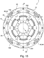
Bei der ersten Ausführungsform der Erfindung (siehe
Das Anschlagelement 44 ist auf einer Axialseite des Pendelmassenträgers 10 als ein langgestreckter Körper ausgebildet, der an den Längsendabschnitten bevorzugt abgerundet ist. Hierbei kann ein radial äußerer Längsendabschnitt in Umfangsrichtung U verdickt ausgebildet sein. Ein Querschnitt dieses Körpers ist in einem Mittenabschnitt bevorzugt im Wesentlichen quadratisch oder rechteckig aufgebaut, wobei die beiden in Umfangsrichtung U liegenden Anschlagsseiten, an welchen die Pendelmassen 22 anschlagen können, bevorzugt im Wesentlichen parallel zueinander liegen. Sie können auch einen kleinen Winkel einschließen, der dem entspricht, welchen die Stirnseiten der betreffenden Pendelmassen 22 bei einer gegenseitigen Anlage einnehmen. Das Anschlagelement 44 ist mit einem vom Körper im Wesentlichen in einem rechten Winkel abstehenden Zylinderabschnitt in der Führungsbahn 130 eingehängt, wobei sich an der dem ersten langgestreckten Körper gegenüberliegenden Axialseite des Pendelmassenträgers 10 bevorzugt ein zweiter im Wesentlichen identischer langgestreckter Körper anschließt, der ebenfalls am Zylinderabschnitt vorgesehen ist. Hierbei ist der Zylinderabschnitt zu einem Längsende des Anschlagelements 44 versetzt angeordnet, so dass sich ein längerer Abschnitt am Pendelmassenträger 10 radial nach innen erstreckt (siehe
In bevorzugten Ausführungsformen der Erfindung ist das Anschlagelement 44 derart konfiguriert, dass dessen größter radialer Querschnitt in einen Querschnitt der Führungsbahn 130 eingeschrieben werden kann, was in der
Bei der zweiten Ausführungsform der Erfindung (siehe
Gemäß der Erfindung können bei beiden Ausführungsformen die Führungsbahnen 130, 230 wiederum derart ausgestaltet sein, dass es zu keinen festen Stößen bzw. Anschlägen der Führungselemente 30 an einem jeweiligen inneren Längsende der Führungsbahnen 130, 230 im Pendelmassenträger 10 und/oder in der Pendelmasse 20 kommt. Hierfür weisen die Führungsbahnen 130, 230 einen entsprechenden Freiwinkel bzw. eine Erweiterung auf, der bzw. die die Führungsbahnen 130, 230 derart verlängert, dass bevor ein Führungselement 30 an einem Längsende der betreffenden Führungsbahn 130, 230 anschlägt, betreffende Pendelmassen 22, z. B. wie in der
Gemäß der Erfindung wird eine Fliehkraftpendeleinrichtung 1 bzw. ein Fliehkraftpendel zur Verfügung gestellt, wobei deren bzw. dessen Pendelmassen 22 über Anschlagelemente 44 gegeneinander abstützbar sind, und/oder die Führungsbahnen 130, 230 für die Führungselemente 30 im Pendelmassenträger 10 und in den Pendelmassen 20 jeweils einen Freiwinkel zum Zweck einer Geräuschreduzierung und Stoßdämpfung aufweisen.According to the invention, a
- 11
- Fliehkraftpendeleinrichtung, insbesondere Trapezfliehkraftpendeleinrichtung; Einrichtung zur drehzahladaptiven SchwingungstilgungCentrifugal pendulum device, in particular trapezoidal centrifugal pendulum device; Device for speed-adaptive vibration damping
- 1010
- Pendelmassenträger, PendelflanschPendulum mass carrier, pendulum flange
- 2020
- Pendelmassenpaar, Tilgermassenpaar, TrägheitsmassenpaarPendulum mass pair, Tilgermassenpaar, inertia mass pair
- 2222
- einzelne Pendelmasse, einzelne Tilgermasse, einzelne Trägheitsmassesingle pendulum mass, single absorber mass, single inertial mass
- 3030
- Führungselement, insbesondere Abrollelement, Zylinderrolle, Gleitelement, Niet, StiftGuide element, in particular rolling element, cylindrical roller, sliding element, rivet, pin
- 4040
- Dämpferelement, StoßdämpferDamper element, shock absorber
- 4242
- Federelement, Druckfederelement, Lamellenfeder(element), Streifenfeder(element)Spring element, compression spring element, leaf spring (element), strip spring (element)
- 4444
- Anschlagelement, Anschlagpuffer insbesondere massives Element (Kunststoff) oder Federanschlagelement (Metall bzw. Metalllegierung)Stop element, stop buffer, in particular solid element (plastic) or spring stop element (metal or metal alloy)
- 123123
-
Durchgangsausnehmung für Zapfen 123 des Befestigungsbereichs 422Through hole for
pin 123 of the mounting portion 422nd - 130130
-
Führungsbahn für Führungselement 30 und ggf. Anschlagelement 44 im Pendelmassenträger 10Guideway for
guide member 30 and possibly stop member 44 in the pendulum mass carrier 10th - 230230
-
Führungsbahn für Führungselement 30 in Pendelmasse 20Guide track for
guide element 30 inpendulum mass 20 - 422422
- Befestigungsbereichfastening area
- 423423
- Zapfen, Niet, Abstandsniet, AbstandsbolzenSpigot, rivet, spacer rivet, spacers
- 424424
- Federbereichspring range
- 442442
- Grundkörperbody
- 444444
- Federeinrichtung, insbesondere Federarm, FederbalkenSpring device, in particular spring arm, spring bar
- AA
-
Axialrichtung der Fliehkraftpendeleinrichtung 1, des Pendelmassenträgers 10, des Pendelmassenpaars 20, etc.Axial direction of the
centrifugal pendulum device 1, thependulum mass carrier 10, thependulum mass pair 20, etc. - RR
-
Radialrichtung der Fliehkraftpendeleinrichtung 1, des Pendelmassenträgers 10, des Pendelmassenpaars 20, etc.Radial direction of the
centrifugal pendulum device 1, thependulum mass carrier 10, thependulum mass pair 20, etc. - SS
-
Rotationsachse der Fliehkraftpendeleinrichtung 1Rotation axis of the
centrifugal pendulum device 1 - UU
-
Umfangsrichtung der Fliehkraftpendeleinrichtung 1, des Pendelmassenträgers 10, des Pendelmassenpaars 20, etcCircumferential direction of the
centrifugal pendulum device 1, thependulum mass carrier 10, thependulum mass pair 20, etc
Claims (6)
- Centrifugal force pendulum device, in particular trapezoidal centrifugal force pendulum device, for a damper device and/or a torque transmission device, in particular for a drive train of a motor vehicle, having a pendulum mass carrier (10) which can be rotated about a rotational axis (S) and on which a plurality of pendulum masses (22) or pendulum mass pairs (20) which can be moved with respect to the pendulum mass carrier (10) are provided in the circumferential direction (U), characterized in that two pendulum masses (22) or pendulum mass pairs (20) which are directly adjacent in the circumferential direction (U) of the pendulum mass carrier (10) can be coupled mechanically with the aid of a stop element (44) which is arranged on the circumferential side between the adjacent pendulum masses and can be moved independently of the pendulum masses, the stop element (44) and/or the relevant guide track (130) in the pendulum mass carrier (10) being dimensioned in such a way that the stop element (44) can be hooked laterally into it.
- Centrifugal force pendulum device according to Claim 1, characterized in that the stop element (44), in particular a stop body of the stop element (44), is a solid element (44) which is preferably constructed from a plastic, and the stop element (44) is configured, in particular, as an elongate body, the stop faces of which for the pendulum masses (22) or pendulum mass pairs (20) are oriented substantially parallel to one another in the circumferential direction (U).
- Centrifugal force pendulum device according to either of Claims 1 and 2, characterized in that the stop element (44) is configured as a spring stop element (44) which has in each case at least one spring device (444) on its two sides in the circumferential direction (U), an individual spring device (444) of the spring stop element (44) preferably being configured as a single-stage or multiple-stage parallel or series arrangement of leaf springs, on which a relevant pendulum mass (22) or a relevant pendulum mass pair (20) can be seated.
- Centrifugal force pendulum device according to Claim 3, characterized in that a guide track (130) of the pendulum mass carrier (10), a guide track (230) of a relevant pendulum mass (22) or a relevant pendulum mass pair (20) and a respective guide element (30) are adapted or designed with respect to one another that, in the case of transitional phases of the pendulum masses (22) or the pendulum mass pairs (20) and/or a maximum swing angle of the centrifugal force pendulum device (1), mutual contact takes place between the pendulum masses (22) or the pendulum mass pairs (20), apart from the spring stop elements (44), mutual contact (10, 30, 20) in the circumferential direction (U) preferably being substantially avoided, furthermore.
- Centrifugal force pendulum device according to one of Claims 1 to 4, characterized in that:• guide tracks (130, 230) of the pendulum mass carrier (10) and/or the pendulum mass (20) or the pendulum mass pairs (20) have a clearance angle in order to avoid collisions between guide elements (30) and the pendulum mass carrier (10);• the relevant guide track (130) in the pendulum mass carrier (10), the stop element (44) and the pendulum masses (22) or the pendulum mass pairs (20) are arranged and/or designed in such a way that the stop element (44) cannot fall out of the guide track (130) even in unfavourable positions;• the stop element (44) for relevant pendulum mass pairs (20) is of double configuration, and the two elements are preferably fixed onto one another via a spacer rivet;• the stop element (44) is configured in one piece, in particular is configured in one piece in material terms, and preferably comprises either a hard and/or wear-resistant plastic or preferably a spring steel;• a maximum axial depth of a stop face or a spring region (424) of the stop element (42) corresponds to that of a pendulum mass (22);
and/or• the stop element (44) which is mounted in the pendulum mass carrier (10) is of wider configuration in the circumferential direction (U) on a radially outer end section than on a central section or a radially inner end section. - Damper device or torque transmission device, in particular for a drive train of a motor vehicle; for example a centrifugal force pendulum, a torque converter, a coupling, a Föttinger coupling, a coupling assembly, a damper, a torsional vibration damper, a turbine damper, a pump damper, a dual-mass converter or a dual-mass flywheel, or a combination thereof; characterized in that the damper device or the torque transmission device has a centrifugal force pendulum device (1) which is configured according to one of Claims 1 to 5.
Applications Claiming Priority (2)
| Application Number | Priority Date | Filing Date | Title |
|---|---|---|---|
| DE102010055897 | 2010-12-23 | ||
| PCT/DE2011/002077 WO2012083920A1 (en) | 2010-12-23 | 2011-12-05 | Centrifugal pendulum mechanism |
Publications (2)
| Publication Number | Publication Date |
|---|---|
| EP2655921A1 EP2655921A1 (en) | 2013-10-30 |
| EP2655921B1 true EP2655921B1 (en) | 2018-09-19 |
Family
ID=45562046
Family Applications (1)
| Application Number | Title | Priority Date | Filing Date |
|---|---|---|---|
| EP11815679.3A Active EP2655921B1 (en) | 2010-12-23 | 2011-12-05 | Centrifugal pendulum mechanism |
Country Status (5)
| Country | Link |
|---|---|
| US (1) | US9328796B2 (en) |
| EP (1) | EP2655921B1 (en) |
| CN (1) | CN103270334B (en) |
| DE (2) | DE102011087693A1 (en) |
| WO (1) | WO2012083920A1 (en) |
Families Citing this family (74)
| Publication number | Priority date | Publication date | Assignee | Title |
|---|---|---|---|---|
| WO2011120485A1 (en) * | 2010-03-11 | 2011-10-06 | Schaeffler Technologies Gmbh & Co. Kg | Centrifugal pendulum device |
| DE102011088925B4 (en) | 2011-12-19 | 2022-01-05 | Zf Friedrichshafen Ag | Vibration damping arrangement, in particular for the drive train of a vehicle |
| CN104520608B (en) * | 2012-07-06 | 2016-08-24 | 舍弗勒技术股份两合公司 | Torsional vibration damper |
| DE102013214155A1 (en) * | 2012-08-06 | 2014-02-06 | Schaeffler Technologies AG & Co. KG | Centrifugal pendulum and friction clutch with centrifugal pendulum |
| JP5881130B2 (en) * | 2012-11-26 | 2016-03-09 | 本田技研工業株式会社 | Centrifugal pendulum damping device |
| DE102012221956A1 (en) * | 2012-11-30 | 2014-06-05 | Schaeffler Technologies Gmbh & Co. Kg | Torque transmission device and drive train with torque transmission device |
| DE102012223563A1 (en) | 2012-12-18 | 2014-06-18 | Schaeffler Technologies Gmbh & Co. Kg | Centrifugal force pendulum utilized in powertrain of motor car, has masses arranged opposite to flange portion at oscillation angle and turning connection that is provided between facing ends of masses around common pivot point |
| FR3000157B1 (en) * | 2012-12-20 | 2015-08-07 | Valeo Embrayages | PENDULUM OSCILLATOR TYPE DAMPING DEVICES FOR EQUIPPING MOTOR VEHICLE TRANSMISSIONS |
| JP6050388B2 (en) | 2013-01-30 | 2016-12-21 | アイシン・エィ・ダブリュ株式会社 | Damper device and starting device |
| DE102014200901A1 (en) * | 2013-02-08 | 2014-08-14 | Schaeffler Technologies Gmbh & Co. Kg | Damper arrangement for chain or belt drive |
| DE102013204711A1 (en) * | 2013-03-18 | 2014-09-18 | Zf Friedrichshafen Ag | Tilgerschwingungsdämpfer |
| DE102014210489A1 (en) | 2013-06-10 | 2014-12-11 | Schaeffler Technologies Gmbh & Co. Kg | centrifugal pendulum |
| DE102013211966A1 (en) * | 2013-06-25 | 2015-01-08 | Zf Friedrichshafen Ag | Tilgerschwingungsdämpfer |
| DE102013213373A1 (en) * | 2013-07-09 | 2015-01-15 | Zf Friedrichshafen Ag | Tilgerschwingungsdämpfer |
| CN105378335B (en) * | 2013-08-09 | 2017-02-01 | 爱信艾达株式会社 | Centrifugal pendulum vibration absorbing device |
| DE102014217451A1 (en) * | 2013-09-04 | 2015-03-05 | Schaeffler Technologies Gmbh & Co. Kg | Centrifugal pendulum stop spring element, centrifugal pendulum device and component assembly |
| DE102014216540A1 (en) | 2013-09-16 | 2015-03-19 | Schaeffler Technologies AG & Co. KG | Centrifugal pendulum device with compression springs |
| WO2015043591A1 (en) * | 2013-09-26 | 2015-04-02 | Schaeffler Technologies AG & Co. KG | Centrifugal pendulum device |
| DE102013220534A1 (en) * | 2013-10-11 | 2015-04-16 | Zf Friedrichshafen Ag | Torsional vibration damper, as well as torsional vibration damper for a drive train of a motor vehicle |
| CN105683617B (en) | 2013-10-24 | 2018-06-29 | 舍弗勒技术股份两合公司 | Torsional oscillation isolating device |
| US9347519B2 (en) | 2013-11-11 | 2016-05-24 | Ford Global Technologies, Llc | Strap mounting for pendulum dampers |
| FR3013415B1 (en) * | 2013-11-15 | 2016-05-27 | Valeo Embrayages | SIMPLIFIED PULSE TORSION DAMPING DEVICE |
| DE112015000246T9 (en) * | 2014-01-17 | 2016-12-01 | Aisin Aw Co., Ltd. | A centrifugal pendulum-type vibration absorbing device and order setting method for the same |
| FR3018883B1 (en) * | 2014-03-20 | 2017-10-20 | Valeo Embrayages | PENDULAR DAMPING DEVICE |
| CN106133387B (en) * | 2014-03-31 | 2018-09-18 | 舍弗勒技术股份两合公司 | Centrifugal pendulum mechanism with director element |
| WO2015149802A1 (en) * | 2014-04-01 | 2015-10-08 | Schaeffler Technologies AG & Co. KG | Centrifugal pendulum device with a protective device |
| WO2015149794A1 (en) * | 2014-04-02 | 2015-10-08 | Schaeffler Technologies AG & Co. KG | Centrifugal pendulum device and torsional vibration damper |
| CN106233034B (en) * | 2014-04-23 | 2020-02-18 | 舍弗勒技术股份两合公司 | Centrifugal pendulum with tensioning device |
| DE102014211740A1 (en) * | 2014-06-18 | 2015-12-24 | Schaeffler Technologies AG & Co. KG | Centrifugal pendulum device |
| DE102014212172B4 (en) * | 2014-06-25 | 2016-06-23 | Schaeffler Technologies AG & Co. KG | centrifugal pendulum |
| DE102014213862A1 (en) | 2014-07-16 | 2016-01-21 | Schaeffler Technologies AG & Co. KG | Centrifugal pendulum device and torque transmission device with centrifugal pendulum device |
| FR3024191B1 (en) * | 2014-07-25 | 2017-06-02 | Valeo Embrayages | DAMPING DEVICE FOR VEHICLE PROPULSION CHAIN |
| DE102014217251A1 (en) * | 2014-08-29 | 2016-03-03 | Schaeffler Technologies AG & Co. KG | centrifugal pendulum |
| JP6201974B2 (en) * | 2014-12-16 | 2017-09-27 | トヨタ自動車株式会社 | Pendulum torsional vibration reduction device |
| JP6176231B2 (en) * | 2014-12-16 | 2017-08-09 | トヨタ自動車株式会社 | Torsional vibration reduction device |
| JP6587388B2 (en) * | 2014-12-24 | 2019-10-09 | 株式会社エクセディ | Dynamic vibration absorber for automobile and lockup device for torque converter |
| DE102015206618A1 (en) * | 2015-04-14 | 2016-10-20 | Schaeffler Technologies AG & Co. KG | centrifugal pendulum |
| KR101708033B1 (en) * | 2015-04-21 | 2017-02-17 | 한국파워트레인 주식회사 | Vibration Reduction Apparatus for Motor Vehicle Torque Converter Using Cross Pendulum |
| DE102016206114A1 (en) * | 2015-04-22 | 2016-10-27 | Schaeffler Technologies AG & Co. KG | centrifugal pendulum |
| FR3036150B1 (en) * | 2015-05-12 | 2019-09-06 | Valeo Embrayages | TORSION OSCILLATION DAMPING DEVICE |
| FR3036762B1 (en) * | 2015-06-01 | 2017-06-02 | Valeo Embrayages | TORSION OSCILLATION DAMPING DEVICE |
| DE102016208493A1 (en) * | 2015-06-25 | 2016-12-29 | Schaeffler Technologies AG & Co. KG | Centrifugal pendulum device with stop for spherical rollers |
| FR3039870B1 (en) * | 2015-08-05 | 2017-07-28 | Valeo Embrayages | TORSION OSCILLATION DAMPING DEVICE |
| FR3039871B1 (en) * | 2015-08-05 | 2018-03-02 | Valeo Embrayages | TORSION OSCILLATION DAMPING DEVICE |
| DE102015215268A1 (en) | 2015-08-11 | 2017-02-16 | Schaeffler Technologies AG & Co. KG | centrifugal pendulum |
| KR101694049B1 (en) | 2015-08-24 | 2017-01-09 | 현대자동차주식회사 | Apparatus for reducing vibration of vehicle |
| DE102015217271A1 (en) * | 2015-09-10 | 2017-03-16 | Schaeffler Technologies AG & Co. KG | torsional vibration dampers |
| WO2017057681A1 (en) * | 2015-09-30 | 2017-04-06 | アイシン・エィ・ダブリュ株式会社 | Vibration damping device |
| FR3046649A1 (en) * | 2016-01-13 | 2017-07-14 | Valeo Embrayages | PENDULAR DAMPING DEVICE |
| DE102016201260A1 (en) | 2016-01-28 | 2017-08-03 | Schaeffler Technologies AG & Co. KG | Centrifugal pendulum device with wear-optimized compression spring |
| DE102017108766A1 (en) | 2016-05-24 | 2017-11-30 | Schaeffler Technologies AG & Co. KG | Centrifugal pendulum device |
| DE102016215134A1 (en) | 2016-08-15 | 2018-02-15 | Schaeffler Technologies AG & Co. KG | centrifugal pendulum |
| CN106326561B (en) * | 2016-08-25 | 2019-10-18 | 同济大学 | A kind of epitrochoid type centrifugal pendulum bump leveller design method |
| DE102016222468A1 (en) * | 2016-11-16 | 2018-05-17 | Schaeffler Technologies AG & Co. KG | Centrifugal pendulum and drive system |
| CN108412958A (en) * | 2017-02-10 | 2018-08-17 | 南京法雷奥离合器有限公司 | Device for damping torsional oscillation |
| WO2018193185A1 (en) * | 2017-04-18 | 2018-10-25 | Valeo Embrayages | Torsion damping device |
| FR3065264B1 (en) * | 2017-04-18 | 2020-02-28 | Valeo Embrayages | TORSION DAMPING DEVICE |
| WO2018199323A1 (en) * | 2017-04-28 | 2018-11-01 | アイシン・エィ・ダブリュ株式会社 | Vibration damping device |
| DE102017110022A1 (en) * | 2017-05-10 | 2018-11-15 | Schaeffler Technologies AG & Co. KG | Centrifugal pendulum device with a biasing element for guiding the cylindrical rollers |
| DE102017111479A1 (en) * | 2017-05-24 | 2018-11-29 | Hengst Se | Method for operating a centrifugal separator |
| DE102018201095A1 (en) | 2018-01-24 | 2019-07-25 | Zf Friedrichshafen Ag | absorber system |
| DE102018201094B4 (en) * | 2018-01-24 | 2023-07-13 | Zf Friedrichshafen Ag | absorber system |
| US20190264775A1 (en) * | 2018-02-26 | 2019-08-29 | Schaeffler Technologies AG & Co. KG | Centrifugal pendulum absorber including springs fixed to circumferential edges of masses |
| DE102018105743A1 (en) * | 2018-03-13 | 2019-09-19 | Schaeffler Technologies AG & Co. KG | Centrifugal pendulum device with a plate spring for generating a frictional resistance; Clutch disc and drive train |
| DE102018106274A1 (en) * | 2018-03-19 | 2019-09-19 | Schaeffler Technologies AG & Co. KG | Tilgereinrichtung and torque transmission device |
| DE102018114057A1 (en) | 2018-06-13 | 2019-12-19 | Schaeffler Technologies AG & Co. KG | Centrifugal pendulum with coupled damper rings from neighboring pendulum masses |
| FR3097927B1 (en) * | 2019-06-28 | 2021-07-23 | Valeo Embrayages | PENDULUM CUSHIONING DEVICE |
| JP7164506B2 (en) * | 2019-10-04 | 2022-11-01 | トヨタ自動車株式会社 | Torsional vibration reduction device |
| DE102019127216B4 (en) * | 2019-10-10 | 2021-12-02 | Schaeffler Technologies AG & Co. KG | Torque transfer device |
| DE102020106462A1 (en) | 2020-03-10 | 2021-09-16 | Schaeffler Technologies AG & Co. KG | Spring-coupled centrifugal pendulum with a carrier flange |
| DE102020107843A1 (en) | 2020-03-23 | 2021-09-23 | Schaeffler Technologies AG & Co. KG | Centrifugal pendulum device, the pendulum masses of which are assigned to resilient spacer plates |
| DE102020113595A1 (en) | 2020-05-20 | 2021-11-25 | Schaeffler Technologies AG & Co. KG | Centrifugal pendulum device |
| DE102020118873A1 (en) | 2020-07-16 | 2022-01-20 | Schaeffler Technologies AG & Co. KG | Centrifugal pendulum for torsional vibration dampers |
| US11396923B2 (en) * | 2020-09-15 | 2022-07-26 | Schaeffler Technologies AG & Co. KG | Centrifugal pendulum absorber with radial travel stop |
Family Cites Families (6)
| Publication number | Priority date | Publication date | Assignee | Title |
|---|---|---|---|---|
| US1716496A (en) * | 1927-01-24 | 1929-06-11 | Chrysler Corp | Vibration dampener |
| DE19704517C2 (en) * | 1997-02-06 | 2003-06-12 | Zf Sachs Ag | Torsional vibration damping device for damping torsional vibrations in a drive train |
| DE19804227B4 (en) * | 1998-02-04 | 2006-03-09 | Zf Sachs Ag | Lock-up clutch with a balancing mass on the torsional vibration damper |
| DE19831160A1 (en) | 1998-07-11 | 2000-01-13 | Freudenberg Carl Fa | Speed-adaptive vibration damper |
| DE102009037481C5 (en) * | 2008-09-18 | 2023-08-24 | Schaeffler Technologies AG & Co. KG | Speed-adaptive absorber, in particular a centrifugal pendulum device |
| DE102009042836A1 (en) * | 2008-11-24 | 2010-05-27 | Luk Lamellen Und Kupplungsbau Beteiligungs Kg | Centrifugal force pendulum for torque transmission device, has rolling body assigned to career shifts, and connecting element arranged between careers of pendulum masses along circumferential direction |
-
2011
- 2011-12-05 WO PCT/DE2011/002077 patent/WO2012083920A1/en active Application Filing
- 2011-12-05 DE DE102011087693A patent/DE102011087693A1/en not_active Withdrawn
- 2011-12-05 CN CN201180062142.5A patent/CN103270334B/en active Active
- 2011-12-05 DE DE112011104566T patent/DE112011104566A5/en not_active Ceased
- 2011-12-05 EP EP11815679.3A patent/EP2655921B1/en active Active
-
2013
- 2013-06-21 US US13/924,182 patent/US9328796B2/en active Active
Non-Patent Citations (1)
| Title |
|---|
| None * |
Also Published As
| Publication number | Publication date |
|---|---|
| DE112011104566A5 (en) | 2013-09-19 |
| US9328796B2 (en) | 2016-05-03 |
| WO2012083920A1 (en) | 2012-06-28 |
| US20130283967A1 (en) | 2013-10-31 |
| CN103270334A (en) | 2013-08-28 |
| DE102011087693A1 (en) | 2012-06-28 |
| CN103270334B (en) | 2015-11-25 |
| EP2655921A1 (en) | 2013-10-30 |
Similar Documents
| Publication | Publication Date | Title |
|---|---|---|
| EP2655921B1 (en) | Centrifugal pendulum mechanism | |
| DE112008003168B4 (en) | Power transmission device, in particular for power transmission between a drive machine and an output | |
| EP2636923B1 (en) | Torsion vibration damper assembly and oscillation damper device, in particular in a torsion vibration damper arrangement | |
| EP2976546B1 (en) | Tuned mass damper | |
| EP2976547B1 (en) | Absorber-type vibration damper | |
| EP2909503B1 (en) | Torsional vibration damper assembly with speed-dependent characteristic | |
| DE10049001C2 (en) | Torsion spring set | |
| DE69928624T2 (en) | Torsionally compliant and damped sprocket engine with position stop | |
| DE19734322B4 (en) | Torsional vibration damper with rolling elements as coupling elements | |
| EP2147229B1 (en) | Shoe having a spring position limitation, or torsional oscillation damper having such a shoe | |
| DE19911564B4 (en) | Vibration damping device | |
| WO2015032398A1 (en) | Centrifugal pendulum stop spring element, centrifugal pendulum device and component arrangement | |
| EP3593008A1 (en) | Centrifugal pendulum and drive arrangement for a motor vehicle | |
| EP3060829A1 (en) | Torsion damper | |
| DE102009050353A1 (en) | Torsional vibration damper for use in drive train of e.g. lorry, has carrier disk designed as flange-like function part, which is axially arranged between centrifugal masses and extends with respect to rotational axis in radial direction | |
| WO2015043587A1 (en) | Centrifugal pendulum device | |
| EP1812728B1 (en) | Torque transmission device | |
| DE102013211966A1 (en) | Tilgerschwingungsdämpfer | |
| DE19857109A1 (en) | Shock absorbing disc arrangement with hub | |
| EP2853772B1 (en) | Torsion vibration damper | |
| WO2022033623A1 (en) | Pendular rocker damper with adjustable friction device, and hybrid powertrain | |
| EP2853773B1 (en) | Torsion vibration damper | |
| DE10210619A1 (en) | damping device | |
| DE102009052978B4 (en) | Torque transfer device | |
| DE102012212895A1 (en) | Centrifugal force pendulum device for power train of internal combustion engine-driven motor car, has pendulum mass provided with mass portions spaced from each other, where mass portions are interconnected by carrier plate |
Legal Events
| Date | Code | Title | Description |
|---|---|---|---|
| PUAI | Public reference made under article 153(3) epc to a published international application that has entered the european phase |
Free format text: ORIGINAL CODE: 0009012 |
|
| 17P | Request for examination filed |
Effective date: 20130723 |
|
| AK | Designated contracting states |
Kind code of ref document: A1 Designated state(s): AL AT BE BG CH CY CZ DE DK EE ES FI FR GB GR HR HU IE IS IT LI LT LU LV MC MK MT NL NO PL PT RO RS SE SI SK SM TR |
|
| RAP1 | Party data changed (applicant data changed or rights of an application transferred) |
Owner name: SCHAEFFLER TECHNOLOGIES GMBH & CO. KG |
|
| DAX | Request for extension of the european patent (deleted) | ||
| RAP1 | Party data changed (applicant data changed or rights of an application transferred) |
Owner name: SCHAEFFLER TECHNOLOGIES AG & CO. KG |
|
| 17Q | First examination report despatched |
Effective date: 20170322 |
|
| GRAP | Despatch of communication of intention to grant a patent |
Free format text: ORIGINAL CODE: EPIDOSNIGR1 |
|
| INTG | Intention to grant announced |
Effective date: 20180430 |
|
| GRAS | Grant fee paid |
Free format text: ORIGINAL CODE: EPIDOSNIGR3 |
|
| GRAA | (expected) grant |
Free format text: ORIGINAL CODE: 0009210 |
|
| AK | Designated contracting states |
Kind code of ref document: B1 Designated state(s): AL AT BE BG CH CY CZ DE DK EE ES FI FR GB GR HR HU IE IS IT LI LT LU LV MC MK MT NL NO PL PT RO RS SE SI SK SM TR |
|
| REG | Reference to a national code |
Ref country code: GB Ref legal event code: FG4D Free format text: NOT ENGLISH |
|
| REG | Reference to a national code |
Ref country code: CH Ref legal event code: EP |
|
| REG | Reference to a national code |
Ref country code: DE Ref legal event code: R096 Ref document number: 502011014755 Country of ref document: DE |
|
| REG | Reference to a national code |
Ref country code: AT Ref legal event code: REF Ref document number: 1043610 Country of ref document: AT Kind code of ref document: T Effective date: 20181015 |
|
| REG | Reference to a national code |
Ref country code: IE Ref legal event code: FG4D Free format text: LANGUAGE OF EP DOCUMENT: GERMAN |
|
| REG | Reference to a national code |
Ref country code: NL Ref legal event code: MP Effective date: 20180919 |
|
| PG25 | Lapsed in a contracting state [announced via postgrant information from national office to epo] |
Ref country code: NO Free format text: LAPSE BECAUSE OF FAILURE TO SUBMIT A TRANSLATION OF THE DESCRIPTION OR TO PAY THE FEE WITHIN THE PRESCRIBED TIME-LIMIT Effective date: 20181219 Ref country code: BG Free format text: LAPSE BECAUSE OF FAILURE TO SUBMIT A TRANSLATION OF THE DESCRIPTION OR TO PAY THE FEE WITHIN THE PRESCRIBED TIME-LIMIT Effective date: 20181219 Ref country code: SE Free format text: LAPSE BECAUSE OF FAILURE TO SUBMIT A TRANSLATION OF THE DESCRIPTION OR TO PAY THE FEE WITHIN THE PRESCRIBED TIME-LIMIT Effective date: 20180919 Ref country code: RS Free format text: LAPSE BECAUSE OF FAILURE TO SUBMIT A TRANSLATION OF THE DESCRIPTION OR TO PAY THE FEE WITHIN THE PRESCRIBED TIME-LIMIT Effective date: 20180919 Ref country code: GR Free format text: LAPSE BECAUSE OF FAILURE TO SUBMIT A TRANSLATION OF THE DESCRIPTION OR TO PAY THE FEE WITHIN THE PRESCRIBED TIME-LIMIT Effective date: 20181220 Ref country code: FI Free format text: LAPSE BECAUSE OF FAILURE TO SUBMIT A TRANSLATION OF THE DESCRIPTION OR TO PAY THE FEE WITHIN THE PRESCRIBED TIME-LIMIT Effective date: 20180919 Ref country code: LT Free format text: LAPSE BECAUSE OF FAILURE TO SUBMIT A TRANSLATION OF THE DESCRIPTION OR TO PAY THE FEE WITHIN THE PRESCRIBED TIME-LIMIT Effective date: 20180919 |
|
| REG | Reference to a national code |
Ref country code: LT Ref legal event code: MG4D |
|
| PG25 | Lapsed in a contracting state [announced via postgrant information from national office to epo] |
Ref country code: HR Free format text: LAPSE BECAUSE OF FAILURE TO SUBMIT A TRANSLATION OF THE DESCRIPTION OR TO PAY THE FEE WITHIN THE PRESCRIBED TIME-LIMIT Effective date: 20180919 Ref country code: LV Free format text: LAPSE BECAUSE OF FAILURE TO SUBMIT A TRANSLATION OF THE DESCRIPTION OR TO PAY THE FEE WITHIN THE PRESCRIBED TIME-LIMIT Effective date: 20180919 Ref country code: AL Free format text: LAPSE BECAUSE OF FAILURE TO SUBMIT A TRANSLATION OF THE DESCRIPTION OR TO PAY THE FEE WITHIN THE PRESCRIBED TIME-LIMIT Effective date: 20180919 |
|
| PG25 | Lapsed in a contracting state [announced via postgrant information from national office to epo] |
Ref country code: RO Free format text: LAPSE BECAUSE OF FAILURE TO SUBMIT A TRANSLATION OF THE DESCRIPTION OR TO PAY THE FEE WITHIN THE PRESCRIBED TIME-LIMIT Effective date: 20180919 Ref country code: NL Free format text: LAPSE BECAUSE OF FAILURE TO SUBMIT A TRANSLATION OF THE DESCRIPTION OR TO PAY THE FEE WITHIN THE PRESCRIBED TIME-LIMIT Effective date: 20180919 Ref country code: IS Free format text: LAPSE BECAUSE OF FAILURE TO SUBMIT A TRANSLATION OF THE DESCRIPTION OR TO PAY THE FEE WITHIN THE PRESCRIBED TIME-LIMIT Effective date: 20190119 Ref country code: PL Free format text: LAPSE BECAUSE OF FAILURE TO SUBMIT A TRANSLATION OF THE DESCRIPTION OR TO PAY THE FEE WITHIN THE PRESCRIBED TIME-LIMIT Effective date: 20180919 Ref country code: ES Free format text: LAPSE BECAUSE OF FAILURE TO SUBMIT A TRANSLATION OF THE DESCRIPTION OR TO PAY THE FEE WITHIN THE PRESCRIBED TIME-LIMIT Effective date: 20180919 Ref country code: CZ Free format text: LAPSE BECAUSE OF FAILURE TO SUBMIT A TRANSLATION OF THE DESCRIPTION OR TO PAY THE FEE WITHIN THE PRESCRIBED TIME-LIMIT Effective date: 20180919 Ref country code: EE Free format text: LAPSE BECAUSE OF FAILURE TO SUBMIT A TRANSLATION OF THE DESCRIPTION OR TO PAY THE FEE WITHIN THE PRESCRIBED TIME-LIMIT Effective date: 20180919 Ref country code: IT Free format text: LAPSE BECAUSE OF FAILURE TO SUBMIT A TRANSLATION OF THE DESCRIPTION OR TO PAY THE FEE WITHIN THE PRESCRIBED TIME-LIMIT Effective date: 20180919 |
|
| PG25 | Lapsed in a contracting state [announced via postgrant information from national office to epo] |
Ref country code: SK Free format text: LAPSE BECAUSE OF FAILURE TO SUBMIT A TRANSLATION OF THE DESCRIPTION OR TO PAY THE FEE WITHIN THE PRESCRIBED TIME-LIMIT Effective date: 20180919 Ref country code: SM Free format text: LAPSE BECAUSE OF FAILURE TO SUBMIT A TRANSLATION OF THE DESCRIPTION OR TO PAY THE FEE WITHIN THE PRESCRIBED TIME-LIMIT Effective date: 20180919 Ref country code: PT Free format text: LAPSE BECAUSE OF FAILURE TO SUBMIT A TRANSLATION OF THE DESCRIPTION OR TO PAY THE FEE WITHIN THE PRESCRIBED TIME-LIMIT Effective date: 20190119 |
|
| REG | Reference to a national code |
Ref country code: DE Ref legal event code: R097 Ref document number: 502011014755 Country of ref document: DE |
|
| PLBE | No opposition filed within time limit |
Free format text: ORIGINAL CODE: 0009261 |
|
| STAA | Information on the status of an ep patent application or granted ep patent |
Free format text: STATUS: NO OPPOSITION FILED WITHIN TIME LIMIT |
|
| PG25 | Lapsed in a contracting state [announced via postgrant information from national office to epo] |
Ref country code: DK Free format text: LAPSE BECAUSE OF FAILURE TO SUBMIT A TRANSLATION OF THE DESCRIPTION OR TO PAY THE FEE WITHIN THE PRESCRIBED TIME-LIMIT Effective date: 20180919 |
|
| REG | Reference to a national code |
Ref country code: CH Ref legal event code: PL |
|
| 26N | No opposition filed |
Effective date: 20190620 |
|
| GBPC | Gb: european patent ceased through non-payment of renewal fee |
Effective date: 20181219 |
|
| PG25 | Lapsed in a contracting state [announced via postgrant information from national office to epo] |
Ref country code: LU Free format text: LAPSE BECAUSE OF NON-PAYMENT OF DUE FEES Effective date: 20181205 Ref country code: MC Free format text: LAPSE BECAUSE OF FAILURE TO SUBMIT A TRANSLATION OF THE DESCRIPTION OR TO PAY THE FEE WITHIN THE PRESCRIBED TIME-LIMIT Effective date: 20180919 |
|
| REG | Reference to a national code |
Ref country code: IE Ref legal event code: MM4A |
|
| REG | Reference to a national code |
Ref country code: BE Ref legal event code: MM Effective date: 20181231 |
|
| PG25 | Lapsed in a contracting state [announced via postgrant information from national office to epo] |
Ref country code: IE Free format text: LAPSE BECAUSE OF NON-PAYMENT OF DUE FEES Effective date: 20181205 Ref country code: SI Free format text: LAPSE BECAUSE OF FAILURE TO SUBMIT A TRANSLATION OF THE DESCRIPTION OR TO PAY THE FEE WITHIN THE PRESCRIBED TIME-LIMIT Effective date: 20180919 Ref country code: FR Free format text: LAPSE BECAUSE OF NON-PAYMENT OF DUE FEES Effective date: 20181231 |
|
| PG25 | Lapsed in a contracting state [announced via postgrant information from national office to epo] |
Ref country code: BE Free format text: LAPSE BECAUSE OF NON-PAYMENT OF DUE FEES Effective date: 20181231 |
|
| PG25 | Lapsed in a contracting state [announced via postgrant information from national office to epo] |
Ref country code: GB Free format text: LAPSE BECAUSE OF NON-PAYMENT OF DUE FEES Effective date: 20181219 Ref country code: CH Free format text: LAPSE BECAUSE OF NON-PAYMENT OF DUE FEES Effective date: 20181231 Ref country code: LI Free format text: LAPSE BECAUSE OF NON-PAYMENT OF DUE FEES Effective date: 20181231 |
|
| PG25 | Lapsed in a contracting state [announced via postgrant information from national office to epo] |
Ref country code: MT Free format text: LAPSE BECAUSE OF FAILURE TO SUBMIT A TRANSLATION OF THE DESCRIPTION OR TO PAY THE FEE WITHIN THE PRESCRIBED TIME-LIMIT Effective date: 20180919 |
|
| REG | Reference to a national code |
Ref country code: AT Ref legal event code: MM01 Ref document number: 1043610 Country of ref document: AT Kind code of ref document: T Effective date: 20181205 |
|
| PG25 | Lapsed in a contracting state [announced via postgrant information from national office to epo] |
Ref country code: TR Free format text: LAPSE BECAUSE OF FAILURE TO SUBMIT A TRANSLATION OF THE DESCRIPTION OR TO PAY THE FEE WITHIN THE PRESCRIBED TIME-LIMIT Effective date: 20180919 |
|
| PG25 | Lapsed in a contracting state [announced via postgrant information from national office to epo] |
Ref country code: AT Free format text: LAPSE BECAUSE OF NON-PAYMENT OF DUE FEES Effective date: 20181205 |
|
| PG25 | Lapsed in a contracting state [announced via postgrant information from national office to epo] |
Ref country code: CY Free format text: LAPSE BECAUSE OF FAILURE TO SUBMIT A TRANSLATION OF THE DESCRIPTION OR TO PAY THE FEE WITHIN THE PRESCRIBED TIME-LIMIT Effective date: 20180919 Ref country code: MK Free format text: LAPSE BECAUSE OF NON-PAYMENT OF DUE FEES Effective date: 20180919 Ref country code: HU Free format text: LAPSE BECAUSE OF FAILURE TO SUBMIT A TRANSLATION OF THE DESCRIPTION OR TO PAY THE FEE WITHIN THE PRESCRIBED TIME-LIMIT; INVALID AB INITIO Effective date: 20111205 |
|
| PGFP | Annual fee paid to national office [announced via postgrant information from national office to epo] |
Ref country code: DE Payment date: 20230216 Year of fee payment: 12 |
|
| P01 | Opt-out of the competence of the unified patent court (upc) registered |
Effective date: 20230522 |