EP2655768B1 - Device for applying laterally retracting doors, particularly for pieces of furniture - Google Patents
Device for applying laterally retracting doors, particularly for pieces of furniture Download PDFInfo
- Publication number
- EP2655768B1 EP2655768B1 EP11790969.7A EP11790969A EP2655768B1 EP 2655768 B1 EP2655768 B1 EP 2655768B1 EP 11790969 A EP11790969 A EP 11790969A EP 2655768 B1 EP2655768 B1 EP 2655768B1
- Authority
- EP
- European Patent Office
- Prior art keywords
- upright
- door
- compartment
- pair
- furniture
- Prior art date
- Legal status (The legal status is an assumption and is not a legal conclusion. Google has not performed a legal analysis and makes no representation as to the accuracy of the status listed.)
- Active
Links
Images



Classifications
-
- E—FIXED CONSTRUCTIONS
- E05—LOCKS; KEYS; WINDOW OR DOOR FITTINGS; SAFES
- E05F—DEVICES FOR MOVING WINGS INTO OPEN OR CLOSED POSITION; CHECKS FOR WINGS; WING FITTINGS NOT OTHERWISE PROVIDED FOR, CONCERNED WITH THE FUNCTIONING OF THE WING
- E05F5/00—Braking devices, e.g. checks; Stops; Buffers
-
- E—FIXED CONSTRUCTIONS
- E05—LOCKS; KEYS; WINDOW OR DOOR FITTINGS; SAFES
- E05D—HINGES OR SUSPENSION DEVICES FOR DOORS, WINDOWS OR WINGS
- E05D15/00—Suspension arrangements for wings
- E05D15/48—Suspension arrangements for wings allowing alternative movements
- E05D15/52—Suspension arrangements for wings allowing alternative movements for opening about a vertical as well as a horizontal axis
-
- E—FIXED CONSTRUCTIONS
- E05—LOCKS; KEYS; WINDOW OR DOOR FITTINGS; SAFES
- E05D—HINGES OR SUSPENSION DEVICES FOR DOORS, WINDOWS OR WINGS
- E05D15/00—Suspension arrangements for wings
- E05D15/56—Suspension arrangements for wings with successive different movements
- E05D15/58—Suspension arrangements for wings with successive different movements with both swinging and sliding movements
-
- E—FIXED CONSTRUCTIONS
- E05—LOCKS; KEYS; WINDOW OR DOOR FITTINGS; SAFES
- E05F—DEVICES FOR MOVING WINGS INTO OPEN OR CLOSED POSITION; CHECKS FOR WINGS; WING FITTINGS NOT OTHERWISE PROVIDED FOR, CONCERNED WITH THE FUNCTIONING OF THE WING
- E05F5/00—Braking devices, e.g. checks; Stops; Buffers
- E05F5/003—Braking devices, e.g. checks; Stops; Buffers for sliding wings
-
- E—FIXED CONSTRUCTIONS
- E05—LOCKS; KEYS; WINDOW OR DOOR FITTINGS; SAFES
- E05Y—INDEXING SCHEME ASSOCIATED WITH SUBCLASSES E05D AND E05F, RELATING TO CONSTRUCTION ELEMENTS, ELECTRIC CONTROL, POWER SUPPLY, POWER SIGNAL OR TRANSMISSION, USER INTERFACES, MOUNTING OR COUPLING, DETAILS, ACCESSORIES, AUXILIARY OPERATIONS NOT OTHERWISE PROVIDED FOR, APPLICATION THEREOF
- E05Y2201/00—Constructional elements; Accessories therefor
- E05Y2201/60—Suspension or transmission members; Accessories therefor
- E05Y2201/606—Accessories therefor
- E05Y2201/62—Synchronisation of suspension or transmission members
-
- E—FIXED CONSTRUCTIONS
- E05—LOCKS; KEYS; WINDOW OR DOOR FITTINGS; SAFES
- E05Y—INDEXING SCHEME ASSOCIATED WITH SUBCLASSES E05D AND E05F, RELATING TO CONSTRUCTION ELEMENTS, ELECTRIC CONTROL, POWER SUPPLY, POWER SIGNAL OR TRANSMISSION, USER INTERFACES, MOUNTING OR COUPLING, DETAILS, ACCESSORIES, AUXILIARY OPERATIONS NOT OTHERWISE PROVIDED FOR, APPLICATION THEREOF
- E05Y2201/00—Constructional elements; Accessories therefor
- E05Y2201/60—Suspension or transmission members; Accessories therefor
- E05Y2201/622—Suspension or transmission members elements
- E05Y2201/624—Arms
- E05Y2201/626—Levers
-
- E—FIXED CONSTRUCTIONS
- E05—LOCKS; KEYS; WINDOW OR DOOR FITTINGS; SAFES
- E05Y—INDEXING SCHEME ASSOCIATED WITH SUBCLASSES E05D AND E05F, RELATING TO CONSTRUCTION ELEMENTS, ELECTRIC CONTROL, POWER SUPPLY, POWER SIGNAL OR TRANSMISSION, USER INTERFACES, MOUNTING OR COUPLING, DETAILS, ACCESSORIES, AUXILIARY OPERATIONS NOT OTHERWISE PROVIDED FOR, APPLICATION THEREOF
- E05Y2900/00—Application of doors, windows, wings or fittings thereof
- E05Y2900/10—Application of doors, windows, wings or fittings thereof for buildings or parts thereof
- E05Y2900/13—Type of wing
- E05Y2900/132—Doors
- E05Y2900/14—Doors disappearing in pockets of a wall, e.g. so-called pocket doors
-
- E—FIXED CONSTRUCTIONS
- E05—LOCKS; KEYS; WINDOW OR DOOR FITTINGS; SAFES
- E05Y—INDEXING SCHEME ASSOCIATED WITH SUBCLASSES E05D AND E05F, RELATING TO CONSTRUCTION ELEMENTS, ELECTRIC CONTROL, POWER SUPPLY, POWER SIGNAL OR TRANSMISSION, USER INTERFACES, MOUNTING OR COUPLING, DETAILS, ACCESSORIES, AUXILIARY OPERATIONS NOT OTHERWISE PROVIDED FOR, APPLICATION THEREOF
- E05Y2900/00—Application of doors, windows, wings or fittings thereof
- E05Y2900/20—Application of doors, windows, wings or fittings thereof for furniture, e.g. cabinets
-
- E—FIXED CONSTRUCTIONS
- E05—LOCKS; KEYS; WINDOW OR DOOR FITTINGS; SAFES
- E05Y—INDEXING SCHEME ASSOCIATED WITH SUBCLASSES E05D AND E05F, RELATING TO CONSTRUCTION ELEMENTS, ELECTRIC CONTROL, POWER SUPPLY, POWER SIGNAL OR TRANSMISSION, USER INTERFACES, MOUNTING OR COUPLING, DETAILS, ACCESSORIES, AUXILIARY OPERATIONS NOT OTHERWISE PROVIDED FOR, APPLICATION THEREOF
- E05Y2900/00—Application of doors, windows, wings or fittings thereof
- E05Y2900/20—Application of doors, windows, wings or fittings thereof for furniture, e.g. cabinets
- E05Y2900/212—Doors disappearing in pockets in the furniture body
Definitions
- the present invention relates to a new device to be applied at least between a side wall of the internal space of a piece of furniture and an adjacent door thereof, in order to make it of the laterally retracting type, during the opening of the internal space.
- the main characteristic of the present invention is to provide for the interposition of a hinge upright along the side of the door that one wishes to render laterally retractable of a piece of furniture, the upright being rendered able to slide in depth, along the outer surface of the shoulder of the internal space of the piece of furniture, and being provided with longitudinal guides, which are integral with the shoulder, for the vertical sliding of one of the two ends of a pair of rockers, each rocker being rendered able to oscillate on a respective pivot, which is hinged integrally with the same shoulder of the internal space and is formed by a pair of arms which converge and are mutually integral; the arm of such arms that is not slidingly engaged with the vertical upright is instead connected to the corresponding arm of the other rocker, by means of a load distribution bar, which is adapted to uniform and discharge the weight of the door onto its upright, with respect to the changeable moment of imbalance in each step of sliding and holding, within the retraction compartment.
- retractable doors have the advantage of minimizing their space occupation, particularly during opening and closing, when swing-doors must rotate about their hinges, with a wide radius of motion of the door, within a surface that accordingly cannot be rendered useful.
- This situation affects the opening, the closure and the positioning of doors for walls, as well as the opening, closure and positioning of doors or door wings for pieces of furniture, with consequent problems in terms of space, particularly in apartments, in offices or in any case in small enclosed spaces.
- retractable doors particularly for masonry
- a more solid and complete form or structure of this traditional method is disclosed for example in EP0417000 .
- a sliding door wing corresponds normally to its full or partial arrangement behind an adjacent visible door wing, both wings being provided with respective guides or tracks for support and translation and the piece of furniture generally not having a blind and fixed front wall, behind which the wing of the compartment to be opened is pushed so as to be concealed.
- a sliding door of a piece of furniture is provided in two vertical elements, both of which are engaged in two front guides, an upper one and a lower one, of the piece of furniture, and are pivoted to an intermediate shoulder, which is not coupled to the guides, and can close by pivoting along one edge onto the shoulder, during the opening of the internal space, in order to be guided and accommodated in a compartment which is lateral with respect to the useful internal space of the piece of furniture.
- the sliding door of a piece of furniture is constituted by a door with a first door wing which is articulated to a second door wing, which is mounted so that it can slide within the retraction compartment, and is characterized in that the first door wing is guided by guiding elements which are arranged on the upper and lower edge and can slide on an upper and lower guide that lies parallel to the front edge and to the inside of the retraction compartment, and in that the supporting element comprises elastic means which can be subjected to torsion during the closure of the door, transmitting to the supporting element a force which is sufficient to cause a retraction motion of the door wings into the folded position within the retraction compartment.
- the aim of the present invention is to be able to provide a device that allows the application of laterally retracting doors, even of good size and weight, in addition to being provided in a single panel, even without the need to hinge and fold two or more elements of a same wing.
- an object of the invention is to provide a device for the application of laterally retracting doors or door wings that can be balanced easily and therefore is extremely lightweight and quiet during translation as well as assuredly durable over time.
- a further object of the present invention is to provide a device for the application of laterally retracting doors or door wings that also allows damping of the opening or closing motion, thus also consolidating even the best operating conditions and durability conditions of the piece of furniture.
- Another object of the present invention is to provide a device for the application of laterally retracting doors or door wings that are capable of covering also the lateral edges or uprights of the piece of furniture, gaining also in terms of volume on its useful internal space, in addition to giving the piece of furniture a higher aesthetic value.
- the device 1 being considered is composed of an upright 10 constituted by a profile, in which the upper end 10a and the lower end 10b are rendered able to slide along the respective profile guides 20 and 25, which are fixed horizontally on the outer surface of the side of the internal space V to which a retractable door A is to be applied.
- the retractable door A and the device 1 being considered can be advantageously accommodated in a retraction compartment B, which is adjacent to the useful internal space V of the piece of furniture M and is completed by an outside wall, with the ceiling and footing of the same piece of furniture.
- the upright or profile 10 has an outer longitudinal groove thereof 11, with a longitudinal cavity that has a semicircular cross-section 12, and an inner longitudinal groove 12a, in addition to a lateral shoulder 13 thereof which is T-shaped.
- the profile 10 is furthermore provided with a wall or longitudinal rib 14 which forms an intermediate compartment 12b, which is open toward the semicircular cavity 12 due to the presence of the longitudinal groove 12a.
- the shoulder 13 of the upright 10 is designed to accommodate the internal compartment 15a of a profile 15 which is provided with a length that is slightly shorter than the length of the upright 10 and has double-C shape, having a compartment 15b which is arranged opposite the compartment 15a and is designed to accommodate the bases of a series of hinges 90, as specified better hereinafter.
- the compartment 15a of the profile 15 is designed to accommodate the shoulder 13 of the upright 10, after longitudinal sliding, in order to be adjusted and locked axially and transversely thereto, according to one of the methods of the already-known type and indicated by way of example with the fixing seat 16 in Figure 3 .
- the upright 10 is rendered able to slide along the guides 20 and 25 by interposition respectively of an upper carriage 30 and of a lower carriage 40, which are conveniently fixed respectively to its ends 10a and 10b.
- an upper carriage 30 is constituted by a plate 31 for supporting a pair of free pulleys 32-33, the plate 31 being provided with a stem 31a with a base plate 31 b on which a pair of screws 34 is rendered able to pass and is adapted to screw onto the threaded seat of at least one contrast plate 35.
- Such contrast plate 35 is accommodated in the compartment 12b of the end 10a of the upright 10 and is provided preferably with shoulders 35b which are adapted to be guided within the groove 12b of the upright 10. The screwing of the screws 34 therefore allows perfect locking of the carriage 30 in the correct position of the end 10a of the upright 10, such position being defined by a head shoulder of the contrast plate 35.
- the carriage 30 is naturally applied to the upper guide 20, accommodating the grooves of the pulleys 32-33 along the rail 21, so as to render it able to slide along the compartment 22 of the upper guide 20, which also inhibits its lateral escape in the presence of its perpendicular upper edge 23.
- the upper guide 20 is provided with a lower compartment 24, which allows the passage of the stroke limiting block 36, which is adapted to abut against an adapted abutment 37, in order to delimit the stopping point of the carriage 30 and therefore of the upright 10 and of the door A in the front part of the retraction compartment B.
- the upright 10 is also provided with a pair of devices 80 for preventing the retraction of the door A into the compartment B, which are actuated by the door A itself which acts on the circular rubber pad 83 of the elastic arm 81, to the opposite end of which a roller 82 is applied.
- the rollers 82 are pushed laterally into a compartment that is provided on the surface of the shoulder of the piece of furniture M, in order to prevent the unwanted retraction of the upright 10 into the retraction compartment B.
- a lower carriage 40 is constituted by a plate 41 for supporting a pair of free rollers 42-43, the plate 41 being provided with a substantially perpendicular stem 41a which is arranged in the compartment 12b of the upright 10 and is associated by means of at least one screw 44 with an external contrast plate 45, which is accommodated in the compartment 11 of the upright 10, for the correct locking of the carriage 40 to its end 10b.
- the lower carriage 40 is naturally applied to the lower guide 25, accommodating its rollers 42-43 along the guiding seat 27, which allows its stroke in depth within the retraction compartment B.
- the lower guide 25 is provided with an upper compartment 28, which allows the passage of the stroke limiting block 46, which is adapted to abut against an abutment 37, in order to delimit the stopping point of the carriage 40, therefore of the upright 10 and of the door A at the rear end of the retraction compartment B.
- a device 80 is provided for preventing the return of the door A into the compartment B, as specified above.
- the positioning and locking of the carriages 30-40 at the ends 10a-10b of the upright 10 allows a perfectly parallel arrangement in the stroke of the carriages 30-40 along the respective guides 20-25 at any time of its motion or positioning of the door A within the retraction compartment B.
- the semicylindrical cavity 12 of the upright 10 is designed to accommodate a pair of annular free wheels 52-53 of two carriages 50, which are inserted therein in the intermediate part of the upright 10, before applying and fixing the upper carriages 30 and/or the lower carriage 40 described so far.
- the intermediate carriages 50 are meant to ensure a dynamic connection of the upright 10, therefore of the door A integrally hinged thereto, with a respective end or arm 61 of a pair of rockers 60 which are described better hereinafter.
- an intermediate carriage 50 is constituted substantially by a plate 51 which, by means of adapted pivots (not shown), is adapted to support the pair of free wheels 52-53, which are accommodated in the semicylindrical cavity 12 of the upright 10, while a contrast plate 54 is guided therein and retained by a pair of lateral guides 51a-51b, which are joined to the base plate 51 for example by means of four screws 56.
- a pivot 59 is integrally applied to the contrast plate 54 and, through the possible interposition of bearings or bushings, hinges the end of an arm 61 of a rocker 60.
- the contrast plate 54 is provided with a nut or threaded protrusion 54a into which the stem of a screw 58 is screwed whose head is accommodated in a compartment 51 c of the base plate 51.
- the contrast plate 54 is forced to perform a translational motion along the guides 51a-51b, with a consequent transverse movement of the pivot 59 and of the end of the arm 61 of the rocker 60.
- By acting on the screw 58 of at least one of the carriages 50 it is thus possible to adjust and fix stably the perfect verticality of the door A and of its upright 10, both during retraction into the compartment B and during swing closure onto the useful internal space V of the piece of furniture M.
- the minimum and maximum length of the stroke of the contrast plate 54 is delimited by a pawl (not shown), which is integral with the plate 51 and can slide within a slot (55) of the contrast plate 54.
- a pair of rockers 60 is associated with the upright 10 by a corresponding number of carriages 50.
- Each rocker 60 is constituted not only by the arm 61 for oscillating connection, which can translate vertically, to the upright 10 by interposition of the respective carriage 50, but also by a second arm 62, which is rigidly connected to the other arm 61, in a position which is for example perpendicular, and is provided with its own oscillation pivot 64.
- each rocker 60 is preferably welded or in any case stably joined to a disk 63 which is coaxial to the pivot 64 and is designed for a possible application of a device for damping the opening and closing motion of the sliding door, as specified better hereinafter.
- the pivot 64 of both rockers 60 is associated stably with the outer surface of the shoulder of the piece of furniture that already supports the depth guides 20-25 within the retraction compartment B, allowing the oscillation of the rockers 60 by interposition, for example, of adapted bushings or bearings (not shown).
- the arms 62 of the two rockers 60 are mutually joined and pivoted by means of a distribution bar 66, which ensures a synchronized oscillation thereof, with respect to the positioning and pushing or pulling motion of the upright 10 and of the door A, along the guides 20 and 25, within the retraction compartment B.
- the sliding door or wing A is stably associated and hinged to the upright 10 by interposition of a portion of a profile 15 which is shaped like a double letter C, as exemplified in particular in Figure 3 , and the internal compartment 15a of which accommodates the crossmember of the profile 13 of the upright 10, after suitable adjustment and locking 16.
- the outer compartment 15b of the portion of profile 15 is designed to accommodate the base 91 of a series of hinges 90, each of which is locked in the chosen vertical position of the profile 15, with the closure and locking of at least one block 92, by means of at least one screw 93, against the outer surface of the profile 15 which is already rendered integral with the upright 10.
- a door A for closing the internal space V of the piece of furniture M is shown in its condition of full retraction within the compartment B of the piece of furniture M, in order to leave the useful internal space V completely open and accessible, being guided and retained therein in this condition by the device 1 being considered.
- the upright 10 In the retraction condition, the upright 10 is accommodated at the rear end of the compartment B, supported and guided vertically by its head carriages 30-40, which slide along the respective guides 20-25 and in turn supporting the door A by means of the series of hinges 90.
- the stable retention of the door A in its condition of full retraction within the compartment B is ensured by the presence of the two arms 61 of the two rockers 60, which can move along the upright 10, by means of the respective carriages 50, thus having their second arms 62, joined by the bar 66, synchronized in the oscillation of the rockers 60, maintaining the verticality of the upright 10 and therefore of the door A at all times of translation and positioning.
- the rotation of the arms 61 of course entails the rotation also of the perpendicular arms 62 of the two respective rockers 60, such rotation being necessarily synchronized due to the presence of the distribution bar 66 which is pivoted to the arms 62.
- the two arms 61 would rotate in a manner which is not synchronized and parallel, with a variation of their distance or center distance along the upright 10, so that the same door A might be extracted in an inclined form, then maintaining a lack of verticality with respect to the piece of furniture M.
- the function of the distribution bar 66 is indeed to always ensure the perfect balancing of the door A and of its upright 10, distributing on the upright 10 not only the cantilever weight of the door A, but also any irregular pulling or pushing motion of t door A moving within the compartment B.
- the device 1 applied to the lateral shoulder of the door A, allows a better utilization of the depth of the internal space V than all the other known solutions. Due to these constructive and functional characterizations, the device 1 being considered therefore allows the application to the piece of furniture M of retracting doors A that are provided as a single panel, even of considerable size and weight, without having to render them folding so that they can be accommodated in the retraction compartment B, with simplicity and safety, in accordance with the specified aim.
- Figures 12 and 13 show that the series of hinges 90 preferably applied to the piece of furniture M is of the double-lever type 95-96, with the result that when the door A is completely closed the door A can be superimposed on the shoulders of the lateral uprights of the piece of furniture M, ensuring their visual concealment, with a considerable aesthetic and visual advantage, in addition to being able to ensure the maximum extent of the useful volume of the piece of furniture M, in accordance with another one of the specified objects.
- the device 1 instead of being applied to the outer surface of the wall of the useful internal space V, can be applied to the internal surface of the outer wall of the retraction compartment B, thus arranging on such surface the guides 20-25 and the pivot 64 of the rockers 60, in addition to the optional box 72 of the damping system cited above and described better hereinafter.
- the internal side of the disk 63 of at least one rocker 60 is provided with a surface in relief 71 which is cam-shaped and is oriented conveniently with respect to the position of the arms 61-62 of the rocker 60.
- the disk or cover 63 is rendered able to rotate on the raised edge of a box 72, which is fixed to the same outer surface of the useful internal space of the piece of furniture M where also the guides 20-25 are fixed and on the bottom of which the pivot 64 for the rotation of each rocker 60 is fixed.
- a pivot 73 is rigidly fixed on the bottom of the box 72, and the end of an arm 74 is pivoted, such arm being provided with a probe roller 75, the opposite end being associated with the end of one or more elastic means 76 whose opposite end is integral with the bottom of the box 72. Due to the traction force of the elastic means 76, the probe 75 is constantly placed in contact with the cam-like profile 71 of the cover 63 of the rocker 60.
- the base of the box 72 is also provided with a series of dampers or oil pressure-controlled braking devices 77, which act in contrast against a series of portions of circular rack 78 which are arranged in suitable grip positions.
- the elastic means 76 return the accumulated effort, pushing the door A toward the outlet of the compartment B. In the final part of the exit, the thrust force of the elastic means 76 is contrasted by the action of the dampers 77 on the racks 78.
- Figures 14-15 and 16 clearly shows that the device 1 being considered also allows a positive application of a damping device in the step of entry and exit of the door A from its retraction compartment B, in order to make the retraction even easier and safer in addition to further increasing its duration over time, in accordance with another one of the specified objects.
- the constructive solution of the device 1 described and illustrated so far can be changed and adapted to different conditions of use.
- the device 1 can also be applied to doors A that are made up of two or more wings which are mutually joined and rendered able to fold by hinges in order to be accommodated in a retraction compartment that must have an adequate width, and likewise it is possible to provide for the application of two mutually opposite retracting doors on the two sides or shoulders of a single piece of furniture.
Landscapes
- Engineering & Computer Science (AREA)
- Mechanical Engineering (AREA)
- Hinges (AREA)
- Cabinets, Racks, Or The Like Of Rigid Construction (AREA)
- Extensible Doors And Revolving Doors (AREA)
- Legs For Furniture In General (AREA)
Description
- The present invention relates to a new device to be applied at least between a side wall of the internal space of a piece of furniture and an adjacent door thereof, in order to make it of the laterally retracting type, during the opening of the internal space.
- The main characteristic of the present invention is to provide for the interposition of a hinge upright along the side of the door that one wishes to render laterally retractable of a piece of furniture, the upright being rendered able to slide in depth, along the outer surface of the shoulder of the internal space of the piece of furniture, and being provided with longitudinal guides, which are integral with the shoulder, for the vertical sliding of one of the two ends of a pair of rockers, each rocker being rendered able to oscillate on a respective pivot, which is hinged integrally with the same shoulder of the internal space and is formed by a pair of arms which converge and are mutually integral; the arm of such arms that is not slidingly engaged with the vertical upright is instead connected to the corresponding arm of the other rocker, by means of a load distribution bar, which is adapted to uniform and discharge the weight of the door onto its upright, with respect to the changeable moment of imbalance in each step of sliding and holding, within the retraction compartment.
- With respect to ordinary swing-doors, retractable doors have the advantage of minimizing their space occupation, particularly during opening and closing, when swing-doors must rotate about their hinges, with a wide radius of motion of the door, within a surface that accordingly cannot be rendered useful. This situation affects the opening, the closure and the positioning of doors for walls, as well as the opening, closure and positioning of doors or door wings for pieces of furniture, with consequent problems in terms of space, particularly in apartments, in offices or in any case in small enclosed spaces.
- According to a predominant method, such retractable doors, particularly for masonry, have an upper edge which is provided with a pair of brackets with corresponding rollers, which are rendered able to slide on a guide which also continues along a blind compartment which is provided in the wall, on the side where one wishes to push the retractable door. A more solid and complete form or structure of this traditional method is disclosed for example in
EP0417000 . - In the specific sector of furniture, the retraction of a sliding door wing corresponds normally to its full or partial arrangement behind an adjacent visible door wing, both wings being provided with respective guides or tracks for support and translation and the piece of furniture generally not having a blind and fixed front wall, behind which the wing of the compartment to be opened is pushed so as to be concealed.
- In any case, again in the furniture sector, solutions have been proposed which tend to translate the sliding door wing for opening, until it is in a position that is parallel to the side wall of the piece of furniture. One of the first known solutions of this type is constituted by
FR 2.690.195 - This solution has indeed solved the problem of eliminating the space occupation of the door when the internal space of the piece of furniture must be opened and must remain open, ensuring minimal space occupation even during the opening and closure of the door. However, the difficulty of supporting the door in a manner that is vertically stable over time, due to its weight which acts on the front and depth guides of the piece of furniture, as well as the delicate nature of the device for rotation at right angles of the door, in order to enter and exit from its retraction compartment, have led to limited use of this solution.
- Another known solution is constituted by the teaching of
DE 19902918 , disclosing the features of the preamble ofclaim 1, according to which the sliding door wing is associated laterally and pivoted to an upright which can perform a translational motion in depth on the side or side element of the piece of furniture, the upright being supported by the ends of two bars that are arranged in a pantograph-like arrangement, in which one end can slide along a guide respectively of the upright and of the bottom of the piece of furniture, and being accommodated in the same compartment that accommodates the retracting door. - Even this solution, despite contributing to solve the problem of the space occupation of the door of a piece of furniture, has encountered limited application, mainly because a substantial extent of the compartment is designed to accommodate the supporting pantograph, even in the case of a door in the retracted condition, with the consequent need to be able to provide doors that only have a small aperture or to provide double-wing doors which are mutually hinged along one edge. In this second case, in addition to the less than exciting aesthetic appearance, there is also a considerable cantilever load that acts on the crosspiece, with a rapid deterioration of its supporting guides. However, the greatest drawback of this solution is constituted by the fact that when the crosspiece is in the closed position, therefore with the door in the retracted condition, its supporting capacity is at its minimum, with a heavy imbalance and misalignment of the doors even during the closure of the piece of furniture.
- A more recent solution has been disclosed in
WO2007/148366 , according to which the sliding door of a piece of furniture is constituted by a door with a first door wing which is articulated to a second door wing, which is mounted so that it can slide within the retraction compartment, and is characterized in that the first door wing is guided by guiding elements which are arranged on the upper and lower edge and can slide on an upper and lower guide that lies parallel to the front edge and to the inside of the retraction compartment, and in that the supporting element comprises elastic means which can be subjected to torsion during the closure of the door, transmitting to the supporting element a force which is sufficient to cause a retraction motion of the door wings into the folded position within the retraction compartment. - Even this solution, despite improving the operating conditions of the above cited
FR 2690195 - These and other similar known solutions, furthermore, often do not provide for the possibility of damping the end of the stroke, during the insertion and extraction of the wing from the lateral compartment, in addition to generally providing for a closed condition of the wing that does not cover the uprights of the piece of furniture and therefore has a negative effect on the utilization of its useful internal space.
- The aim of the present invention is to be able to provide a device that allows the application of laterally retracting doors, even of good size and weight, in addition to being provided in a single panel, even without the need to hinge and fold two or more elements of a same wing.
- Within this aim, an object of the invention is to provide a device for the application of laterally retracting doors or door wings that can be balanced easily and therefore is extremely lightweight and quiet during translation as well as assuredly durable over time.
- A further object of the present invention is to provide a device for the application of laterally retracting doors or door wings that also allows damping of the opening or closing motion, thus also consolidating even the best operating conditions and durability conditions of the piece of furniture.
- Another object of the present invention is to provide a device for the application of laterally retracting doors or door wings that are capable of covering also the lateral edges or uprights of the piece of furniture, gaining also in terms of volume on its useful internal space, in addition to giving the piece of furniture a higher aesthetic value.
- This aim and these and other objects are indeed perfectly achieved with the present invention, which provides for the interposition of a pivoting upright along the side of the door that one wishes to render laterally retractable of a piece of furniture, said upright being rendered able to slide in depth and being associated with a pair of rockers which it is adapted to render able to oscillate according to the content of
claim 1. - A better comprehension of the proposed device and a clarification of the achievement of the specified aim and objects are described and illustrated in greater detail hereinafter according to a purely indicative and non-limiting constructive embodiment thereof, also with the aid of the accompanying drawings and wherein:
-
Figure 1 is a perspective view of the arrangement of the main parts that constitute the device for applying laterally retracting doors for pieces of furniture or wardrobes and the like, according to the present invention; -
Figure 2 is a perspective view of the same device asFigure 1 , taken from its opposite side; -
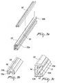
Figure 3a is a perspective view of the upright and of a profile thereof, which can be associated in order to allow the hinged support of the door to the device ofFigures 1 and 2 , shown in a flat position for graphic convenience; -
Figure 3b is an enlarged partial perspective view of a detail ofFigure 3a ; -
Figure 3c is an enlarged partial perspective view of a detail ofFigure 3b ; -
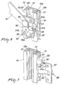
Figure 4 is a partial enlarged-scale and detailed perspective view of the elements that constitute the upper part of the device ofFigures 1 and 2 ; -
Figure 5 is a partial enlarged-scale and detailed perspective view of the elements that constitute the lower part of the device ofFigures 1 and 2 ; -
Figure 6 is a partial enlarged-scale and detailed perspective view of the elements that constitute the central part of the device ofFigures 1 and 2 ; -
Figure 7 is a partial enlarged-scale and detailed perspective view of the fixing of the hinges to the profile ofFigure 3 ; -
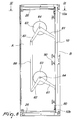
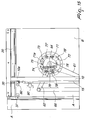
Figure 8 is an elevation view of the device ofFigures 1 and 2 , applied to the side of a piece of furniture and associated with the edge of the door, such door being arranged in its condition of full accommodation within the retraction compartment that is adjacent to the useful internal space of the piece of furniture, the device and the door being shown along the sectional line VIII-VIII ofFigure 9 ; -
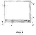
Figure 9 is a plan view of the piece of furniture, of the retractable door and of its sliding device, taken along the sectional line IX-IX ofFigure 8 ; -
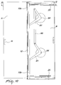
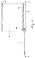
Figure 10 is an elevation view of the device ofFigures 1 and 2 , applied on the same side of the piece of furniture ofFigure 8 , the piece of furniture being shown with the door fully extracted from its retraction compartment or doing insertion, along the sectional linee X-X ofFigure 11 ; -
Figure 11 is a plan view of the piece of furniture and of the device ofFigure 10 , taken along its sectional line XI-XI; -
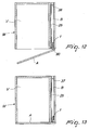
Figure 12 is a plan view of the piece of furniture and of the device ofFigure 11 , in an enlarged form and with the door already extracted from the retraction compartment, being shown in a step of partial swing closure onto the internal space of the piece of furniture; -
Figure 13 is a plan view of the piece of furniture and of the device ofFigure 12 , shown in the condition of complete closure of the door onto its useful internal space; -
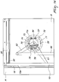
Figure 14 is a partial enlarged-scale vertical view of the piece of furniture and of the device ofFigure 10 , illustrating the possibility to apply a system for damping the sliding motion of the door, shown in the damping condition in the final step of extraction or initial step of insertion of the door in its retraction compartment; -
Figure 15 is a vertical, partial and enlarged-scale view of the piece of furniture and device ofFigure 14 , shown in an intermediate condition of accommodation of the door in its retraction compartment, with the damping system in the condition of maximum reaction; -
Figure 16 is a partial and enlarged-scale vertical view of the piece of furniture and device ofFigures 14 and15 , shown in a condition of full accommodation of the door within its retraction compartment, with the damping system shown in its final step of actuation. - In all the figures, the same details are represented, or are understood to be represented, with the same reference numeral.
- With particular reference to
Figures 1, 2 ,3a, 3b and 3c , one can see that thedevice 1 being considered is composed of an upright 10 constituted by a profile, in which theupper end 10a and thelower end 10b are rendered able to slide along therespective profile guides device 1 being considered can be advantageously accommodated in a retraction compartment B, which is adjacent to the useful internal space V of the piece of furniture M and is completed by an outside wall, with the ceiling and footing of the same piece of furniture. - In greater detail, the upright or
profile 10 has an outer longitudinal groove thereof 11, with a longitudinal cavity that has asemicircular cross-section 12, and an innerlongitudinal groove 12a, in addition to alateral shoulder 13 thereof which is T-shaped. Theprofile 10 is furthermore provided with a wall orlongitudinal rib 14 which forms anintermediate compartment 12b, which is open toward thesemicircular cavity 12 due to the presence of thelongitudinal groove 12a. - The
shoulder 13 of the upright 10 is designed to accommodate theinternal compartment 15a of aprofile 15 which is provided with a length that is slightly shorter than the length of the upright 10 and has double-C shape, having acompartment 15b which is arranged opposite thecompartment 15a and is designed to accommodate the bases of a series ofhinges 90, as specified better hereinafter. - The
compartment 15a of theprofile 15 is designed to accommodate theshoulder 13 of the upright 10, after longitudinal sliding, in order to be adjusted and locked axially and transversely thereto, according to one of the methods of the already-known type and indicated by way of example with thefixing seat 16 inFigure 3 . - As already mentioned, the upright 10 is rendered able to slide along the
guides upper carriage 30 and of alower carriage 40, which are conveniently fixed respectively to itsends - With reference to
Figure 4 , anupper carriage 30 is constituted by aplate 31 for supporting a pair of free pulleys 32-33, theplate 31 being provided with astem 31a with abase plate 31 b on which a pair ofscrews 34 is rendered able to pass and is adapted to screw onto the threaded seat of at least onecontrast plate 35.Such contrast plate 35 is accommodated in thecompartment 12b of theend 10a of the upright 10 and is provided preferably withshoulders 35b which are adapted to be guided within thegroove 12b of the upright 10. The screwing of thescrews 34 therefore allows perfect locking of thecarriage 30 in the correct position of theend 10a of the upright 10, such position being defined by a head shoulder of thecontrast plate 35. - The
carriage 30 is naturally applied to theupper guide 20, accommodating the grooves of the pulleys 32-33 along therail 21, so as to render it able to slide along thecompartment 22 of theupper guide 20, which also inhibits its lateral escape in the presence of its perpendicularupper edge 23. - Finally, the
upper guide 20 is provided with alower compartment 24, which allows the passage of thestroke limiting block 36, which is adapted to abut against an adaptedabutment 37, in order to delimit the stopping point of thecarriage 30 and therefore of the upright 10 and of the door A in the front part of the retraction compartment B. - Proximate to the
upper end 10a andlower end 10b, therefore preferably close to thecarriages devices 80 for preventing the retraction of the door A into the compartment B, which are actuated by the door A itself which acts on thecircular rubber pad 83 of theelastic arm 81, to the opposite end of which aroller 82 is applied. During the rotation of the door A, for its swing closure onto the internal space V, therollers 82 are pushed laterally into a compartment that is provided on the surface of the shoulder of the piece of furniture M, in order to prevent the unwanted retraction of the upright 10 into the retraction compartment B. When the door A is in the initial step of its accommodation in the compartment B, therubber pad 83 slides along the surface of the door A, rotating thearm 81, until theroller 82 is made to exit from its seat, and the stroke of the door A within the compartment B is released, according to a known method and as exemplified inFigure 5 . - Again with reference to
Figure 5 , alower carriage 40 is constituted by aplate 41 for supporting a pair of free rollers 42-43, theplate 41 being provided with a substantiallyperpendicular stem 41a which is arranged in thecompartment 12b of the upright 10 and is associated by means of at least onescrew 44 with anexternal contrast plate 45, which is accommodated in thecompartment 11 of the upright 10, for the correct locking of thecarriage 40 to itsend 10b. - The
lower carriage 40 is naturally applied to thelower guide 25, accommodating its rollers 42-43 along the guidingseat 27, which allows its stroke in depth within the retraction compartment B. - Finally, the
lower guide 25 is provided with anupper compartment 28, which allows the passage of thestroke limiting block 46, which is adapted to abut against anabutment 37, in order to delimit the stopping point of thecarriage 40, therefore of theupright 10 and of the door A at the rear end of the retraction compartment B. Proximate to thelower end 10b adevice 80 is provided for preventing the return of the door A into the compartment B, as specified above. - Of course, the positioning and locking of the carriages 30-40 at the
ends 10a-10b of theupright 10 allows a perfectly parallel arrangement in the stroke of the carriages 30-40 along the respective guides 20-25 at any time of its motion or positioning of the door A within the retraction compartment B. - With reference to the various
Figures 1 to 6 , thesemicylindrical cavity 12 of theupright 10 is designed to accommodate a pair of annular free wheels 52-53 of twocarriages 50, which are inserted therein in the intermediate part of theupright 10, before applying and fixing theupper carriages 30 and/or thelower carriage 40 described so far. Theintermediate carriages 50 are meant to ensure a dynamic connection of theupright 10, therefore of the door A integrally hinged thereto, with a respective end orarm 61 of a pair ofrockers 60 which are described better hereinafter. - In particular, with reference to
Figure 6 , anintermediate carriage 50 is constituted substantially by aplate 51 which, by means of adapted pivots (not shown), is adapted to support the pair of free wheels 52-53, which are accommodated in thesemicylindrical cavity 12 of theupright 10, while acontrast plate 54 is guided therein and retained by a pair of lateral guides 51a-51b, which are joined to thebase plate 51 for example by means of fourscrews 56. Apivot 59 is integrally applied to thecontrast plate 54 and, through the possible interposition of bearings or bushings, hinges the end of anarm 61 of arocker 60. - The
contrast plate 54 is provided with a nut or threadedprotrusion 54a into which the stem of ascrew 58 is screwed whose head is accommodated in acompartment 51 c of thebase plate 51. - By turning the
screw 58, thecontrast plate 54 is forced to perform a translational motion along theguides 51a-51b, with a consequent transverse movement of thepivot 59 and of the end of thearm 61 of therocker 60. By acting on thescrew 58 of at least one of thecarriages 50, it is thus possible to adjust and fix stably the perfect verticality of the door A and of itsupright 10, both during retraction into the compartment B and during swing closure onto the useful internal space V of the piece of furniture M. The minimum and maximum length of the stroke of thecontrast plate 54 is delimited by a pawl (not shown), which is integral with theplate 51 and can slide within a slot (55) of thecontrast plate 54. - With particular reference to
Figures 1 and 2 , a pair ofrockers 60 is associated with the upright 10 by a corresponding number ofcarriages 50. Eachrocker 60 is constituted not only by thearm 61 for oscillating connection, which can translate vertically, to theupright 10 by interposition of therespective carriage 50, but also by asecond arm 62, which is rigidly connected to theother arm 61, in a position which is for example perpendicular, and is provided with itsown oscillation pivot 64. - According to the solution exemplified also in
Figures 8 and10 and14 to 16 , thearms rocker 60 are preferably welded or in any case stably joined to adisk 63 which is coaxial to thepivot 64 and is designed for a possible application of a device for damping the opening and closing motion of the sliding door, as specified better hereinafter. - In any case, according to the solution of the accompanying figures, the
pivot 64 of bothrockers 60 is associated stably with the outer surface of the shoulder of the piece of furniture that already supports the depth guides 20-25 within the retraction compartment B, allowing the oscillation of therockers 60 by interposition, for example, of adapted bushings or bearings (not shown). - In turn, the
arms 62 of the tworockers 60 are mutually joined and pivoted by means of adistribution bar 66, which ensures a synchronized oscillation thereof, with respect to the positioning and pushing or pulling motion of theupright 10 and of the door A, along theguides - As already mentioned, the sliding door or wing A is stably associated and hinged to the
upright 10 by interposition of a portion of aprofile 15 which is shaped like a double letter C, as exemplified in particular inFigure 3 , and theinternal compartment 15a of which accommodates the crossmember of theprofile 13 of theupright 10, after suitable adjustment and locking 16. - With particular reference to
Figure 7 , theouter compartment 15b of the portion ofprofile 15 is designed to accommodate thebase 91 of a series ofhinges 90, each of which is locked in the chosen vertical position of theprofile 15, with the closure and locking of at least oneblock 92, by means of at least onescrew 93, against the outer surface of theprofile 15 which is already rendered integral with theupright 10. - Having thus described the main parts of the device being considered and their intermediate arrangement, between the shoulder of the piece of furniture and the edge of the sliding door or wing A, within the retraction compartment B of the piece of furniture M, their operation is summarized hereinafter also in relation to compliance with the specified aim and objects, with the aid in particular of
Figures 8 to 13 . - With reference to
Figures 8 and9 , a door A for closing the internal space V of the piece of furniture M is shown in its condition of full retraction within the compartment B of the piece of furniture M, in order to leave the useful internal space V completely open and accessible, being guided and retained therein in this condition by thedevice 1 being considered. - In the retraction condition, the
upright 10 is accommodated at the rear end of the compartment B, supported and guided vertically by its head carriages 30-40, which slide along the respective guides 20-25 and in turn supporting the door A by means of the series of hinges 90. The stable retention of the door A in its condition of full retraction within the compartment B is ensured by the presence of the twoarms 61 of the tworockers 60, which can move along theupright 10, by means of therespective carriages 50, thus having theirsecond arms 62, joined by thebar 66, synchronized in the oscillation of therockers 60, maintaining the verticality of theupright 10 and therefore of the door A at all times of translation and positioning. - With reference to
Figures 10 and11 , as already mentioned, the moment of maximum extraction of the door A from the retraction compartment B of the piece of furniture M, for example by manual action by means of the recessed handle m, is shown. With the extraction of the door A of course there is also the simultaneous extraction of theupright 10, which by sliding along its guides 20-25 also engages thearms 61 of the tworockers 60 so as to rotate about theirpivot 64. In fact, since therockers 60 have theirpivot 64 fixed integrally to the same wall that also supports the guides 20-25, the translation of the upright 10 causes the rotation of thearms 61 of the tworockers 60, such rotation being facilitated by the interposition of thecarriages 50 between the ends of thearms 61 and theupright 10. By means of thecarriages 50 it is still possible to render thearms 61 able to oscillate along theupright 10. - The rotation of the
arms 61 of course entails the rotation also of theperpendicular arms 62 of the tworespective rockers 60, such rotation being necessarily synchronized due to the presence of thedistribution bar 66 which is pivoted to thearms 62. - If the
bar 62 is not present in thedevice 1 being considered, upon an accidental obstacle while pulling the door A or upon pulling it irregularly, the twoarms 61 would rotate in a manner which is not synchronized and parallel, with a variation of their distance or center distance along theupright 10, so that the same door A might be extracted in an inclined form, then maintaining a lack of verticality with respect to the piece of furniture M. - The function of the
distribution bar 66 is indeed to always ensure the perfect balancing of the door A and of itsupright 10, distributing on the upright 10 not only the cantilever weight of the door A, but also any irregular pulling or pushing motion of t door A moving within the compartment B. - In the constructive solution exemplified so far, the
device 1, applied to the lateral shoulder of the door A, allows a better utilization of the depth of the internal space V than all the other known solutions. Due to these constructive and functional characterizations, thedevice 1 being considered therefore allows the application to the piece of furniture M of retracting doors A that are provided as a single panel, even of considerable size and weight, without having to render them folding so that they can be accommodated in the retraction compartment B, with simplicity and safety, in accordance with the specified aim. - The presence of the pair of
rockers 60 which cooperates with the upright 10 in order to support and balance the translational motion of the door A in the retraction compartment B makes this movement extremely light and quiet, in accordance with another one of the specified objects. - With reference to
Figures 12 and 13 , the fact becomes clear that once the step of full extraction of the door A from the retraction compartment B has ended, thecarriages device 80. - With the upright 10 arranged at the edge of the retraction compartment B and with the
bases 91 of thehinges 90 integrally fixed to theprofile 15 of theupright 10, the double pair of movable levers 95-96 of thehinges 90, i.e. their fixingbase 97, protrude, with respect to the edge of the retraction compartment B, allowing the rotary motion of the door A, until any intermediate position thereof ofFigure 12 and of complete swing closure ofFigure 13 is reached. -
Figures 12 and 13 show that the series ofhinges 90 preferably applied to the piece of furniture M is of the double-lever type 95-96, with the result that when the door A is completely closed the door A can be superimposed on the shoulders of the lateral uprights of the piece of furniture M, ensuring their visual concealment, with a considerable aesthetic and visual advantage, in addition to being able to ensure the maximum extent of the useful volume of the piece of furniture M, in accordance with another one of the specified objects. - According to a first constructive variation of the present device for the application of laterally retracting doors, the
device 1, instead of being applied to the outer surface of the wall of the useful internal space V, can be applied to the internal surface of the outer wall of the retraction compartment B, thus arranging on such surface the guides 20-25 and thepivot 64 of therockers 60, in addition to theoptional box 72 of the damping system cited above and described better hereinafter. - With particular reference to
Figures 14-15 and16 , as already mentioned, a partial front view in phantom lines of a preferential application of a system 70 for damping the translational motion of the door A and of itsupright 10 within its retraction compartment B is illustrated. - In greater detail, also with reference to
Figures 1 and 2 , the internal side of thedisk 63 of at least onerocker 60 is provided with a surface inrelief 71 which is cam-shaped and is oriented conveniently with respect to the position of the arms 61-62 of therocker 60. - The disk or cover 63 is rendered able to rotate on the raised edge of a
box 72, which is fixed to the same outer surface of the useful internal space of the piece of furniture M where also the guides 20-25 are fixed and on the bottom of which thepivot 64 for the rotation of eachrocker 60 is fixed. - A
pivot 73 is rigidly fixed on the bottom of thebox 72, and the end of anarm 74 is pivoted, such arm being provided with aprobe roller 75, the opposite end being associated with the end of one or more elastic means 76 whose opposite end is integral with the bottom of thebox 72. Due to the traction force of the elastic means 76, theprobe 75 is constantly placed in contact with the cam-like profile 71 of thecover 63 of therocker 60. - The base of the
box 72 is also provided with a series of dampers or oil pressure-controlledbraking devices 77, which act in contrast against a series of portions ofcircular rack 78 which are arranged in suitable grip positions. - With particular reference to
Figure 14 , the condition is shown in which theupright 10 is arranged at the end of the retraction compartment B and thecam 71 of the disk or cover 63 has a surface ofmaximum eccentricity 71a which is arranged upstream of the point of contact of theprobe 75 with the elastic means 76 that react to the entry of the door A in the retraction compartment B, whereas the engagement of thedampers 77 on theracks 78 is irrelevant, since they have a single direction of rotation in which they apply their dissipative function. - With reference to
Figure 15 , the condition is shown in which the surface ofmaximum eccentricity 71a of thecam 71 is axially aligned with theprobe 75, constituting the dead center between the step of manual pushing of the door A within the compartment B and the subsequent step in which the elastic means 76 react to push the door A into the compartment B again without the influence of the contact between thedamper 77 and theracks 78. - With reference to
Figure 16 , the condition is shown in which the surface ofmaximum eccentricity 71 a is arranged abundantly far from theprobe 75 and the pushing action of the elastic means 76 is braked by the action of the dampers 77' on the racks 78', until the abutment of the upright 10 against thestroke limiting abutments 38 within the compartment B is guided. - In order to extract the door A from the compartment B starting from the position of
Figure 16 , the door A is pulled out manually, with gradual loading of the elastic means 76, due to the contact of theprobe 75 with the risingpart 71a of theeccentric element 71, the action of the dampers 77' on the racks 78' being irrelevant, until the same dead center ofFigure 15 is reached. - Once the dead center has been passed, the elastic means 76 return the accumulated effort, pushing the door A toward the outlet of the compartment B. In the final part of the exit, the thrust force of the elastic means 76 is contrasted by the action of the
dampers 77 on theracks 78. - The description of
Figures 14-15 and16 clearly shows that thedevice 1 being considered also allows a positive application of a damping device in the step of entry and exit of the door A from its retraction compartment B, in order to make the retraction even easier and safer in addition to further increasing its duration over time, in accordance with another one of the specified objects. - Of course, the constructive solution of the
device 1 described and illustrated so far can be changed and adapted to different conditions of use. By way of example, one wishes to indicate the possibility of joining in an upward region the two walls of the retraction compartment B by means of a plate or thin laminated element, so as to be able to have a door A that can also cover the upper edge of the internal space V, having an adequate height of the compartment B despite ensuring adequate protection of thedevice 1 against dust and making the entire piece of furniture M more solid. - It is furthermore possible to apply the
cam 71 and the consequent dampingbox 72 only to one of the tworockers 60, and likewise the presence of thedampers 77 and of the ring gears 78 also can be excluded or replaced with other conventional braking systems. - It is furthermore possible to provide a different angular ratio between the
arms rockers 60, and it is likewise possible to provide for the application to theshoulder 13 of theupright 10 of a different type ofprofile 15 to which any type of hinge 19 among conventional ones provided with pairs of movable levers 95-96 is to be fixed. - Based on what has been described and illustrated so far, it is evident that the
device 1 can also be applied to doors A that are made up of two or more wings which are mutually joined and rendered able to fold by hinges in order to be accommodated in a retraction compartment that must have an adequate width, and likewise it is possible to provide for the application of two mutually opposite retracting doors on the two sides or shoulders of a single piece of furniture. - These and other similar modifications or adaptations are in any case understood to fall within the novelty of the invention for which protection is claimed.
- The disclosures in
Italian Patent Application No. BL2010A000020 - Where technical features mentioned in any claim are followed by reference signs, those reference signs have been included for the sole purpose of increasing the intelligibility of the claims and accordingly, such reference signs do not have any limiting effect on the interpretation of each element identified by way of example by such reference signs.
Claims (16)
- A device (1) for applying a laterally retracting door (A), particularly for a piece of furniture (M), at least between a side wall of a useful internal space (V) of the piece of furniture (M) and the door (A) thereof, in order to be able to render the door (A) laterally retracting during the opening of said internal space (V), the device (1) comprising:an upright (10) adapted to be interposed between said side wall and an edge of the door (A) for providing sliding of the door (A) and pivoting of the door (A) by means of hinges (90) supported by said upright (10);longitudinal guides (20, 25) adapted to be fixed horizontally on an outer surface of said side wall, said upright (10) having an upper end (10a) and a lower end (10b) slidably connected to said longitudinal guides (20, 25) such that said upright (10) is rendered able to slide within the depth in a retraction compartment (B) of the piece of furniture (M) when the device (1) is mounted in the piece of furniture (M);
the device being characterized in that it further comprises;a pair of rockers (60) each formed by a pair of arms (61, 62) which are mutually integrally formed under an angle and converge for example mutually perpendicularly, a first arm (61) of said pair of arms (61,62) of each one of said pair of rockers (60) being vertically slidingly connected to said upright (10), second arms (62) of said pair of arms (61,62) of said pair of rockers (60) being mutually interconnected by means of a load distribution bar (66); anda respective oscillation pivot (64), adapted to be integrally pivoted on said outer surface of said side wall, arranged at the point of convergence for said pair of arms (61,62) for each one of said pair of rockers (60). - The device according to claim 1, characterized in that said upright (10) is formed by a profile.
- The device (1) according to claim 2, characterized in that the upright (10) has an outer longitudinal groove (11), with a longitudinal cavity having an elongated semicircular cross-section (12) and an inner longitudinal groove (12a), and a lateral shoulder (13) which is T-shaped that is adapted to accommodate a longitudinal profile (15), on which hinges (90) are applied for the support and pivoting of the door (A).
- The device (1) according to claim 3, characterized in that the upright (10) is slidably connected along the guides (20, 25) by interposition respectively of an upper carriage (30) and of a lower carriage (40), which are fixed respectively to said upper and lower ends (10a, 10b) of said upright (10).
- The device (1) according to claim 4, characterized in that said upper carriage (30) is constituted by a plate (31) for supporting a pair of free pulleys (32, 33), said plate (31) being provided with a stem (31a) with a base plate (31b) on which a pair of screws (34) is made to pass through and is screwed onto a threaded seat of at least one contrast plate (35), which is accommodated in a compartment (12b) of the upper end (10a) of the upright (10), and is provided with shoulders (35b) which are adapted to be guided within the compartment (12b) of the same upright (10).
- The device (1) according to claim 5, characterized in that the upper carriage (30) is applied to the upper guide (20), accommodating grooves of the pulleys (32-33) along a rail (21) of the upper guide (20), so as to render said upper carriage (30) slidable along a compartment (22) of said upper guide (20), which inhibits lateral exit of the upper carriage (30), in the presence also of a perpendicular upper edge (23) of the upper guide (20).
- The device (1) according to claim 4, characterized in that said lower carriage (40) is constituted by a plate (41) supporting a pair of free rollers (42, 43), said plate (41) being provided with a substantially perpendicular stem (41a) which is arranged in the compartment (12b) of the upright (10) and is associated, by means of at least one screw (44), with an external contrast plate (45), which is accommodated in the outer longitudinal groove (11) of said upright (10), for the correct locking of the carriage (40) at said lower end (10b).
- The device (1) according to claim 7, characterized in that the lower carriage (40) is applied to the lower guide (25), accommodating said free rollers (42, 43) along a guiding seat (27) of the lower guide (25) that allows a depth stroke of the lower carriage (40) within a retraction compartment (B) of the piece of furniture (M).
- The device (1) according to claim 3, characterized in that the longitudinal cavity (12) of the upright (10) accommodates a pair of annular free wheels (52-53) of two carriages (50), which are inserted therein in an intermediate part of the upright (10) for ensuring a dynamic connection of the upright (10), therefore of the door (A) integrally hinged thereto, with said first arm (61) of said pair of rockers (60).
- The device (1) according to claim 9, characterized in that each said carriage (50) is constituted by a plate (51) which, by means of pivots, supports a pair of free wheels (52-53), while a contrast plate (54) is guided thereat and retained by a pair of lateral guides (51a-51b), with a stroke that is limited by a slot (55) which accommodates a pin which is integral with the plate (51), said contrast plate (54) being provided with a pivot (59) that pivots and allows the oscillation of the end of said first arm (61) of said rocker (60).
- The device (1) according to claim 10, characterized in that the contrast plate (54) is provided with a threaded protrusion (54a), in which the stem of a screw (58) is screwed whose head is accommodated in a compartment (51c) of the base plate (50), so that by rotating said screw (58) the contrast plate (54) is forced to perform a translational motion along the guides (51a, 51b), with consequent transverse movement of the pivot (59) and of the end of the arm (61) of the rocker (60), thus allowing adjustment for perfect verticality of the door (A) and of the upright (10) when the device (1) is mounted, both during retraction into a retraction compartment (B) of the piece of furniture (M) and during swing closure onto the useful internal space (V) of the piece of furniture (M).
- The device (1) according to claim 11, characterized in that said pair of rockers (60) is associated with the upright (10) by means of a corresponding number of said carriages (50), each rocker (60), being constituted by said first arm (61) for connection, which can oscillate and perform a vertical translation with respect to the upright (10) by the interposition of the respective carriage (50), and by said second arm (62), which is connected rigidly to the first arm (61), in a substantially perpendicular position, and is provided with its own said oscillation pivot (64), said arms (61, 62) of each rocker (60) being joined stably to a disk (63) which is coaxial with respect to their pivot (64) and is designed for a device for damping the opening and closing motion of the sliding door (A).
- The device (1) according to claim 12, characterized in that the pivot (64) of both rockers (60) is associated stably with the same surface of the piece of furniture that already supports the depth guides (20-25) within the retraction compartment (B), allowing the oscillation of said rockers (60).
- The device (1) according to claim 13, characterized in that the second arms (62) of the two rockers (60) are mutually joined and pivoted by means of the distribution bar (66), which ensures a synchronized oscillation thereof with respect to the positioning and pushing or pulling motion of the upright (10) and of the door (A) along the guides (20, 25) within the retraction compartment (B).
- The device (1) according to claim 14, characterized in that it is connectable to one or the other of the internal surfaces of the compartment (B) for the retraction of the door (A), arranging on said surface the guides (20-25) and the pivot (64) of the rockers (60), in addition to a box (72) of a damping system.
- The device (1) according to claim 15, characterized in that a cam (71) is shaped on an internal side of the disk (63) of at least one of the two rockers (60) and is oriented with respect to the first and second arms (61-62), said disk (63) being able to rotate on a raised edge of the box (72) a base of which is fixed to the same surface that supports the guides (20-25) and supports a pivot (73) that provides a fulcrum to an arm (74) which is provided with a probe roller (75), said probe roller (75) being arranged in contact with the edge of the cam (71) by way of elastic means (76), in order to facilitate the motion of extraction and insertion of the door (A) in the retraction compartment (B), while dampers limit the speed of said door (A) proximate to the points of initial and final arrival within the compartment (B).
Applications Claiming Priority (2)
| Application Number | Priority Date | Filing Date | Title |
|---|---|---|---|
| ITBL2010A000020A IT1402815B1 (en) | 2010-12-03 | 2010-12-03 | DEVICE FOR THE APPLICATION OF DOORS WITH SIDE DISAPPEARANCE, PARTICULARLY FOR FURNITURE |
| PCT/EP2011/071512 WO2012072738A1 (en) | 2010-12-03 | 2011-12-01 | Device for applying laterally retracting doors, particularly for pieces of furniture |
Publications (2)
| Publication Number | Publication Date |
|---|---|
| EP2655768A1 EP2655768A1 (en) | 2013-10-30 |
| EP2655768B1 true EP2655768B1 (en) | 2016-08-03 |
Family
ID=43736746
Family Applications (1)
| Application Number | Title | Priority Date | Filing Date |
|---|---|---|---|
| EP11790969.7A Active EP2655768B1 (en) | 2010-12-03 | 2011-12-01 | Device for applying laterally retracting doors, particularly for pieces of furniture |
Country Status (9)
| Country | Link |
|---|---|
| US (1) | US9057216B2 (en) |
| EP (1) | EP2655768B1 (en) |
| JP (1) | JP6006728B2 (en) |
| CN (1) | CN103443378B (en) |
| BR (1) | BR112013013053B1 (en) |
| ES (1) | ES2602558T3 (en) |
| IT (1) | IT1402815B1 (en) |
| RU (1) | RU2567717C2 (en) |
| WO (1) | WO2012072738A1 (en) |
Cited By (1)
| Publication number | Priority date | Publication date | Assignee | Title |
|---|---|---|---|---|
| EP4424960A1 (en) * | 2023-03-03 | 2024-09-04 | Hawa Sliding Solutions AG | Hinge device, stop hinge and functional unit |
Families Citing this family (32)
| Publication number | Priority date | Publication date | Assignee | Title |
|---|---|---|---|---|
| US9440727B2 (en) * | 2014-07-11 | 2016-09-13 | B/E Aerospace, Inc. | Telescoping aircraft panel door |
| US9976336B2 (en) * | 2014-07-11 | 2018-05-22 | B/E Aerospace, Inc. | Telescoping aircraft panel door |
| AT516567B1 (en) * | 2014-11-26 | 2018-01-15 | Blum Gmbh Julius | Arrangement of a furniture door and a cavity |
| US9598887B2 (en) * | 2015-02-18 | 2017-03-21 | Margaret B. Reed | Hidden hinge door system and method for use in residential and commercial buildings |
| WO2017066559A1 (en) * | 2015-10-14 | 2017-04-20 | B/E Aerospace, Inc. | Aircraft passenger suite privacy screen control apparatus and method |
| US9894996B1 (en) * | 2016-10-31 | 2018-02-20 | Larry Mitchell Grela | Cabinet |
| AT519246B1 (en) * | 2017-01-13 | 2018-05-15 | Blum Gmbh Julius | Guide system for guiding a movably mounted furniture part |
| AT519515B1 (en) * | 2017-01-13 | 2023-02-15 | Blum Gmbh Julius | facility arrangement |
| DE102017104181A1 (en) * | 2017-02-28 | 2018-08-30 | ambigence GmbH & Co. KG | Furniture |
| DE102017104182A1 (en) * | 2017-02-28 | 2018-08-30 | ambigence GmbH & Co. KG | Furniture |
| AT519903B1 (en) * | 2017-05-11 | 2022-09-15 | Blum Gmbh Julius | Rail for guiding a slide of a furniture door |
| IT201700078326A1 (en) * | 2017-07-12 | 2019-01-12 | Bortoluzzi Sistemi Spa | "FURNITURE WITH SLIDING DOORS AND FOLDABLE DOORS" |
| CN107461097B (en) * | 2017-09-01 | 2022-11-18 | 广东东泰五金精密制造有限公司 | Elastic movable structure of rotating wheel of furniture sliding door |
| CN111406143B (en) * | 2017-11-28 | 2022-03-22 | 博尔托卢齐系统股份公司 | Servo mechanism for furniture leaf |
| CN108060848B (en) * | 2018-01-05 | 2023-08-15 | 广东东泰五金精密制造有限公司 | Furniture rotary opening and closing locking structure |
| DE102018100674B4 (en) * | 2018-01-12 | 2020-03-05 | Hettich-Oni Gmbh & Co. Kg | Furniture plate with a hinge and furniture with such a furniture plate |
| PL3569806T3 (en) * | 2018-05-17 | 2022-01-17 | Kesseböhmer Holding Kg | Lid fitting for swingable mounting of a furniture lid to a furniture unit |
| DE102018120661A1 (en) * | 2018-08-23 | 2020-02-27 | ambigence GmbH & Co. KG | Furniture component and manufacturing method |
| AT521133B1 (en) * | 2018-11-14 | 2019-11-15 | Blum Gmbh Julius | Guide system for guiding a movably mounted door leaf |
| AT521365B1 (en) | 2018-12-20 | 2020-01-15 | Blum Gmbh Julius | Guide system for guiding at least one movably mounted door leaf |
| EP3980619B1 (en) * | 2019-06-07 | 2023-09-13 | Hawa Sliding Solutions AG | Piece of furniture having a door held by a translation device |
| AT522441B1 (en) * | 2019-12-19 | 2020-11-15 | Blum Gmbh Julius | Guide arrangement for guiding at least one sliding door or folding sliding door |
| AT523270B1 (en) * | 2019-12-19 | 2021-07-15 | Blum Gmbh Julius | Arrangement for guiding a sliding door or folding sliding door |
| AT17257U1 (en) * | 2019-12-19 | 2021-10-15 | Blum Gmbh Julius | Method for assembling a guide arrangement for a movable furniture part |
| CN111622641B (en) * | 2020-06-15 | 2021-10-01 | 中山市欧派克五金制品有限公司 | Synchronous sliding mechanism, side hidden door system and cabinet body with side hidden door system |
| CN111749584A (en) * | 2020-06-19 | 2020-10-09 | 广东威法定制家居股份有限公司 | Side-push hidden door connecting device and storage cabinet |
| KR102946462B1 (en) * | 2020-08-28 | 2026-03-31 | 스가쓰네 고우교 가부시키가이샤 | Door guide |
| AT524380A1 (en) * | 2020-10-22 | 2022-05-15 | Blum Gmbh Julius | Method for moving at least one door leaf |
| AT524607B1 (en) * | 2020-12-17 | 2024-02-15 | Blum Gmbh Julius | Arrangement for guiding a movable piece of furniture |
| AT524324B1 (en) | 2020-12-17 | 2022-05-15 | Blum Gmbh Julius | Bearing device for bearing at least one door leaf |
| IT202200017850A1 (en) * | 2022-08-31 | 2024-03-02 | Diana Alessandro | Double-Sided Door with Integrated Universal Hinge |
| WO2025185823A1 (en) | 2024-03-06 | 2025-09-12 | Hawa Sliding Solutions Ag | Hinge device, stop hinge and functional unit |
Family Cites Families (49)
| Publication number | Priority date | Publication date | Assignee | Title |
|---|---|---|---|---|
| US245605A (en) * | 1881-08-16 | Door-hanger | ||
| US423280A (en) * | 1890-03-11 | Door-hanger | ||
| US511208A (en) * | 1893-12-19 | Sliding-door hanger | ||
| US352906A (en) * | 1886-11-23 | James allan | ||
| US374859A (en) * | 1887-12-13 | Sliding-door hanger | ||
| US863286A (en) * | 1905-07-21 | 1907-08-13 | James L Kershaw | Sectional bookcase. |
| US899049A (en) * | 1908-01-27 | 1908-09-22 | Frederick Joseph Honor | Bookcase. |
| US972412A (en) * | 1909-08-04 | 1910-10-11 | Maurice Taussig | Disappearing door. |
| US984793A (en) * | 1909-10-05 | 1911-02-21 | Frank Olander | Equalizer. |
| US1348680A (en) * | 1918-09-17 | 1920-08-03 | Solomon Himmel | Door-equalizer |
| US1513849A (en) * | 1923-07-25 | 1924-11-04 | Mortimer H Moore | Safe |
| US1720050A (en) * | 1928-03-27 | 1929-07-09 | Grand Rapids Store Equip Co | Disappearing door structure |
| US1930547A (en) * | 1930-06-07 | 1933-10-17 | Lyon Metal Products Inc | Cabinet construction |
| US1909849A (en) * | 1931-03-17 | 1933-05-16 | Remington Rand Inc | Door mounting for safes |
| US1933904A (en) * | 1931-05-16 | 1933-11-07 | Miles W Hawks | Garage door operating mechanism |
| US2632926A (en) * | 1950-08-14 | 1953-03-31 | Dowlong Mfg Co | Sliding door and hardware therefor |
| US2709029A (en) * | 1952-11-12 | 1955-05-24 | Paul F Nockels | Packaging machine for cartons |
| US2774644A (en) * | 1954-02-15 | 1956-12-18 | Ray A Patterson | Drawer and stabilizing means therefor |
| US3359684A (en) * | 1965-08-02 | 1967-12-26 | Dura Corp | Actuator with fixed pivot |
| US3456995A (en) * | 1967-04-11 | 1969-07-22 | Gen Electric | Slide-in cabinet door |
| US3570579A (en) * | 1968-03-18 | 1971-03-16 | Nippon Musical Instruments Mfg | Sliding cover and housing device thereof |
| US3724133A (en) * | 1970-04-03 | 1973-04-03 | Nippon Denso Co | Means for opening and closing a window assembly of a vehicle |
| DE2263073C2 (en) * | 1972-12-22 | 1982-11-25 | Robert Krause KG Zweigniederlassung Weilheim/Teck, 7315 Weilheim | Extension fitting for a first plate and a second plate, such as a table or worktop |
| JPH021427Y2 (en) * | 1981-02-02 | 1990-01-12 | ||
| CH670224A5 (en) * | 1983-04-20 | 1989-05-31 | Cwa Const Sa | |
| JPS6219112A (en) * | 1985-07-19 | 1987-01-27 | 大建工業株式会社 | Receiving apparatus |
| CH670555A5 (en) * | 1986-07-02 | 1989-06-30 | Karl Haab | |
| AT392321B (en) * | 1986-10-16 | 1991-03-11 | Alfit Gmbh | FITTING FOR BOX FURNITURE EQUIPPED WITH SWIVEL-SLIDING DOORS AND THE LIKE |
| US4729612A (en) * | 1987-02-27 | 1988-03-08 | Stone Allen F | Hinge support system |
| US4821375A (en) * | 1988-01-29 | 1989-04-18 | Viking Metal Cabinet Co., Inc. | Recessing hinge mechanism |
| US4976502A (en) * | 1989-04-25 | 1990-12-11 | Herman Miller, Inc. | Cabinet with pocketing doors |
| US5078461A (en) * | 1989-04-25 | 1992-01-07 | Herman Miller, Inc. | Cabinet with pocketing doors |
| DE59003645D1 (en) * | 1989-03-14 | 1994-01-13 | Karl Haab | Piece of furniture with retractable door. |
| DD295975A5 (en) * | 1989-03-14 | 1991-11-21 | Karl Haab Und Otto Haab,Ch | MOEBELSTUECK WITH FASCINABLE DOOR |
| US4974912A (en) * | 1989-04-05 | 1990-12-04 | Standard Precision, Inc. | Pocket door suspension system |
| FR2651530A1 (en) | 1989-09-07 | 1991-03-08 | Azoulay Benjamin | SLIDING DOOR HANGING SUSPENDED. |
| IT1259209B (en) * | 1992-04-02 | 1996-03-11 | CABINET WITH FOLDING AND RETRACTABLE SLIDING DOORS | |
| JP2518473Y2 (en) * | 1992-11-18 | 1996-11-27 | 高橋金物株式会社 | Vertical flipper door mounting structure |
| JP2593774Y2 (en) * | 1993-12-29 | 1999-04-12 | スガツネ工業株式会社 | Cabinet with flipper door |
| CH693070A5 (en) * | 1998-02-02 | 2003-02-14 | Hawa Ag | Fastening device a foldable door. |
| DE29808185U1 (en) * | 1998-05-06 | 1998-08-27 | Arturo Salice S.P.A., Novedrate, Como | Furniture with a body part that can be closed by a double-leaf sliding door |
| US6994410B2 (en) * | 2002-09-10 | 2006-02-07 | Knape & Vogt Manufacturing Co. | Pocket door slide |
| DE102005020440A1 (en) | 2005-04-29 | 2006-11-09 | Glasbau Hahn Gmbh + Co. Kg | Display cabinet has door mounted on rollers which slide in C-profile rails at top and bottom, door being mounted on hinges which allow it to swivel so that it rests against side of cabinet when it reaches its end position |
| ITMI20060943A1 (en) | 2006-05-12 | 2007-11-13 | System Holz Spa | NOBODY |
| ITMI20061214A1 (en) * | 2006-06-23 | 2007-12-24 | Dada S P A | WARDROBE OR SIMILAR CABINET WITH FOLDING AND SLIDING DOORS WITH DISAPPEARANCE |
| US20080218043A1 (en) * | 2006-11-15 | 2008-09-11 | Angelo Gianelo | Drawer guidance mechanism |
| US8104850B2 (en) * | 2007-05-30 | 2012-01-31 | Steelcase Inc. | Furniture storage unit |
| ES2397458T3 (en) * | 2009-04-28 | 2013-03-07 | Hawa Ag | Displacement device for pivotally supporting separation elements, and furniture article |
| DE202011002810U1 (en) * | 2011-02-16 | 2011-06-09 | Inter Ikea Systems B.V. | Mechanism for sliding door |
-
2010
- 2010-12-03 IT ITBL2010A000020A patent/IT1402815B1/en active
-
2011
- 2011-12-01 WO PCT/EP2011/071512 patent/WO2012072738A1/en not_active Ceased
- 2011-12-01 US US13/884,400 patent/US9057216B2/en active Active
- 2011-12-01 EP EP11790969.7A patent/EP2655768B1/en active Active
- 2011-12-01 JP JP2013541351A patent/JP6006728B2/en active Active
- 2011-12-01 RU RU2013130228/12A patent/RU2567717C2/en active
- 2011-12-01 CN CN201180057854.8A patent/CN103443378B/en active Active
- 2011-12-01 ES ES11790969.7T patent/ES2602558T3/en active Active
- 2011-12-01 BR BR112013013053A patent/BR112013013053B1/en active IP Right Grant
Cited By (1)
| Publication number | Priority date | Publication date | Assignee | Title |
|---|---|---|---|---|
| EP4424960A1 (en) * | 2023-03-03 | 2024-09-04 | Hawa Sliding Solutions AG | Hinge device, stop hinge and functional unit |
Also Published As
| Publication number | Publication date |
|---|---|
| BR112013013053A2 (en) | 2016-08-09 |
| JP6006728B2 (en) | 2016-10-12 |
| JP2014500417A (en) | 2014-01-09 |
| ES2602558T3 (en) | 2017-02-21 |
| CN103443378A (en) | 2013-12-11 |
| IT1402815B1 (en) | 2013-09-27 |
| RU2013130228A (en) | 2015-01-10 |
| EP2655768A1 (en) | 2013-10-30 |
| CN103443378B (en) | 2015-09-09 |
| US9057216B2 (en) | 2015-06-16 |
| WO2012072738A1 (en) | 2012-06-07 |
| US20130232878A1 (en) | 2013-09-12 |
| ITBL20100020A1 (en) | 2012-06-04 |
| BR112013013053B1 (en) | 2020-04-14 |
| RU2567717C2 (en) | 2015-11-10 |
Similar Documents
| Publication | Publication Date | Title |
|---|---|---|
| US9057216B2 (en) | Device for applying laterally retracting doors, particularly for pieces of furniture | |
| JP2014500417A5 (en) | ||
| US8763205B2 (en) | Running gear arrangement having a guide rail for a sliding door | |
| EP2167769B1 (en) | Mechanism for the aligned closure of sliding doors, in particular for units of furniture or compartments with two or more doors | |
| CN100587221C (en) | Sliding door | |
| US8671633B2 (en) | Foldable sliding wall and carriage | |
| CN110199080B (en) | Guide system for furniture parts | |
| EP2032791B1 (en) | Cabinet or similar article of furniture with a sliding foldaway door | |
| US8499816B2 (en) | Sectional door particularly for garage | |
| FI84289C (en) | Mounting device for a window or door half or equivalent | |
| RU2600922C2 (en) | Fittings for window or door wings left in position close to parallel and horizontally movable in this parallel-left position | |
| CN110199081A (en) | Rail assembly for furniture parts | |
| US20150068124A1 (en) | Support and operating device of sliding doors, in particular for wardrobes | |
| TW201829897A (en) | Guide system for door wings | |
| CN103328748B (en) | Control of the closing movement of a sliding leaf with closing damped fittings | |
| RU2547647C2 (en) | Fittings for sliding fold of window or door | |
| WO2007132290A1 (en) | Hanging cabinet with overturning doors | |
| FI3109385T3 (en) | Closure device for a door with a single or multi-part door leaf | |
| IT201900009945A1 (en) | ADJUSTABLE CONCEALED HINGE FOR WINDOWS | |
| KR101947445B1 (en) | Damping system of elbows with sliding type 3 doors | |
| JPS61282575A (en) | Vertical moving window | |
| WO2013056865A1 (en) | Aluminum profile structure for door and window frames | |
| IT202300004719A1 (en) | PACKABLE DOOR WINDOWS | |
| JP3538577B2 (en) | Sliding door movement control device for suspension type sliding door device | |
| ITPN20010027A1 (en) | GUIDE SYSTEM FOR GROUPS OF DOORS OF SLIDING DOORS ALIGNED COMPLANALLY IN CLOSING, PARTICULARLY FOR WARDROBES AND SIMILAR |
Legal Events
| Date | Code | Title | Description |
|---|---|---|---|
| PUAI | Public reference made under article 153(3) epc to a published international application that has entered the european phase |
Free format text: ORIGINAL CODE: 0009012 |
|
| 17P | Request for examination filed |
Effective date: 20130605 |
|
| AK | Designated contracting states |
Kind code of ref document: A1 Designated state(s): AL AT BE BG CH CY CZ DE DK EE ES FI FR GB GR HR HU IE IS IT LI LT LU LV MC MK MT NL NO PL PT RO RS SE SI SK SM TR |
|
| RIN1 | Information on inventor provided before grant (corrected) |
Inventor name: GIROTTO, ADRIANO Inventor name: BORTOLUZZI, GUIDO |
|
| DAX | Request for extension of the european patent (deleted) | ||
| 17Q | First examination report despatched |
Effective date: 20150512 |
|
| RAP1 | Party data changed (applicant data changed or rights of an application transferred) |
Owner name: BORTOLUZZI SISTEMI S.P.A. |
|
| GRAP | Despatch of communication of intention to grant a patent |
Free format text: ORIGINAL CODE: EPIDOSNIGR1 |
|
| INTG | Intention to grant announced |
Effective date: 20160218 |
|
| GRAS | Grant fee paid |
Free format text: ORIGINAL CODE: EPIDOSNIGR3 |
|
| GRAA | (expected) grant |
Free format text: ORIGINAL CODE: 0009210 |
|
| AK | Designated contracting states |
Kind code of ref document: B1 Designated state(s): AL AT BE BG CH CY CZ DE DK EE ES FI FR GB GR HR HU IE IS IT LI LT LU LV MC MK MT NL NO PL PT RO RS SE SI SK SM TR |
|
| REG | Reference to a national code |
Ref country code: GB Ref legal event code: FG4D |
|
| REG | Reference to a national code |
Ref country code: CH Ref legal event code: EP Ref country code: AT Ref legal event code: REF Ref document number: 817461 Country of ref document: AT Kind code of ref document: T Effective date: 20160815 |
|
| REG | Reference to a national code |
Ref country code: IE Ref legal event code: FG4D |
|
| REG | Reference to a national code |
Ref country code: DE Ref legal event code: R096 Ref document number: 602011028845 Country of ref document: DE |
|
| REG | Reference to a national code |
Ref country code: FR Ref legal event code: PLFP Year of fee payment: 6 |
|
| REG | Reference to a national code |
Ref country code: NL Ref legal event code: MP Effective date: 20160803 |
|
| REG | Reference to a national code |
Ref country code: LT Ref legal event code: MG4D |
|
| REG | Reference to a national code |
Ref country code: AT Ref legal event code: MK05 Ref document number: 817461 Country of ref document: AT Kind code of ref document: T Effective date: 20160803 |
|
| PG25 | Lapsed in a contracting state [announced via postgrant information from national office to epo] |
Ref country code: IS Free format text: LAPSE BECAUSE OF FAILURE TO SUBMIT A TRANSLATION OF THE DESCRIPTION OR TO PAY THE FEE WITHIN THE PRESCRIBED TIME-LIMIT Effective date: 20161203 Ref country code: HR Free format text: LAPSE BECAUSE OF FAILURE TO SUBMIT A TRANSLATION OF THE DESCRIPTION OR TO PAY THE FEE WITHIN THE PRESCRIBED TIME-LIMIT Effective date: 20160803 Ref country code: NL Free format text: LAPSE BECAUSE OF FAILURE TO SUBMIT A TRANSLATION OF THE DESCRIPTION OR TO PAY THE FEE WITHIN THE PRESCRIBED TIME-LIMIT Effective date: 20160803 Ref country code: RS Free format text: LAPSE BECAUSE OF FAILURE TO SUBMIT A TRANSLATION OF THE DESCRIPTION OR TO PAY THE FEE WITHIN THE PRESCRIBED TIME-LIMIT Effective date: 20160803 Ref country code: NO Free format text: LAPSE BECAUSE OF FAILURE TO SUBMIT A TRANSLATION OF THE DESCRIPTION OR TO PAY THE FEE WITHIN THE PRESCRIBED TIME-LIMIT Effective date: 20161103 Ref country code: FI Free format text: LAPSE BECAUSE OF FAILURE TO SUBMIT A TRANSLATION OF THE DESCRIPTION OR TO PAY THE FEE WITHIN THE PRESCRIBED TIME-LIMIT Effective date: 20160803 Ref country code: LT Free format text: LAPSE BECAUSE OF FAILURE TO SUBMIT A TRANSLATION OF THE DESCRIPTION OR TO PAY THE FEE WITHIN THE PRESCRIBED TIME-LIMIT Effective date: 20160803 |
|
| REG | Reference to a national code |
Ref country code: ES Ref legal event code: FG2A Ref document number: 2602558 Country of ref document: ES Kind code of ref document: T3 Effective date: 20170221 |
|
| PG25 | Lapsed in a contracting state [announced via postgrant information from national office to epo] |
Ref country code: AT Free format text: LAPSE BECAUSE OF FAILURE TO SUBMIT A TRANSLATION OF THE DESCRIPTION OR TO PAY THE FEE WITHIN THE PRESCRIBED TIME-LIMIT Effective date: 20160803 Ref country code: GR Free format text: LAPSE BECAUSE OF FAILURE TO SUBMIT A TRANSLATION OF THE DESCRIPTION OR TO PAY THE FEE WITHIN THE PRESCRIBED TIME-LIMIT Effective date: 20161104 Ref country code: PT Free format text: LAPSE BECAUSE OF FAILURE TO SUBMIT A TRANSLATION OF THE DESCRIPTION OR TO PAY THE FEE WITHIN THE PRESCRIBED TIME-LIMIT Effective date: 20161205 Ref country code: PL Free format text: LAPSE BECAUSE OF FAILURE TO SUBMIT A TRANSLATION OF THE DESCRIPTION OR TO PAY THE FEE WITHIN THE PRESCRIBED TIME-LIMIT Effective date: 20160803 Ref country code: LV Free format text: LAPSE BECAUSE OF FAILURE TO SUBMIT A TRANSLATION OF THE DESCRIPTION OR TO PAY THE FEE WITHIN THE PRESCRIBED TIME-LIMIT Effective date: 20160803 Ref country code: SE Free format text: LAPSE BECAUSE OF FAILURE TO SUBMIT A TRANSLATION OF THE DESCRIPTION OR TO PAY THE FEE WITHIN THE PRESCRIBED TIME-LIMIT Effective date: 20160803 |
|
| PG25 | Lapsed in a contracting state [announced via postgrant information from national office to epo] |
Ref country code: EE Free format text: LAPSE BECAUSE OF FAILURE TO SUBMIT A TRANSLATION OF THE DESCRIPTION OR TO PAY THE FEE WITHIN THE PRESCRIBED TIME-LIMIT Effective date: 20160803 Ref country code: RO Free format text: LAPSE BECAUSE OF FAILURE TO SUBMIT A TRANSLATION OF THE DESCRIPTION OR TO PAY THE FEE WITHIN THE PRESCRIBED TIME-LIMIT Effective date: 20160803 |
|
| REG | Reference to a national code |
Ref country code: DE Ref legal event code: R097 Ref document number: 602011028845 Country of ref document: DE |
|
| PG25 | Lapsed in a contracting state [announced via postgrant information from national office to epo] |
Ref country code: BE Free format text: LAPSE BECAUSE OF FAILURE TO SUBMIT A TRANSLATION OF THE DESCRIPTION OR TO PAY THE FEE WITHIN THE PRESCRIBED TIME-LIMIT Effective date: 20160803 Ref country code: DK Free format text: LAPSE BECAUSE OF FAILURE TO SUBMIT A TRANSLATION OF THE DESCRIPTION OR TO PAY THE FEE WITHIN THE PRESCRIBED TIME-LIMIT Effective date: 20160803 Ref country code: SM Free format text: LAPSE BECAUSE OF FAILURE TO SUBMIT A TRANSLATION OF THE DESCRIPTION OR TO PAY THE FEE WITHIN THE PRESCRIBED TIME-LIMIT Effective date: 20160803 Ref country code: SK Free format text: LAPSE BECAUSE OF FAILURE TO SUBMIT A TRANSLATION OF THE DESCRIPTION OR TO PAY THE FEE WITHIN THE PRESCRIBED TIME-LIMIT Effective date: 20160803 Ref country code: CZ Free format text: LAPSE BECAUSE OF FAILURE TO SUBMIT A TRANSLATION OF THE DESCRIPTION OR TO PAY THE FEE WITHIN THE PRESCRIBED TIME-LIMIT Effective date: 20160803 Ref country code: BG Free format text: LAPSE BECAUSE OF FAILURE TO SUBMIT A TRANSLATION OF THE DESCRIPTION OR TO PAY THE FEE WITHIN THE PRESCRIBED TIME-LIMIT Effective date: 20161103 |
|
| PLBE | No opposition filed within time limit |
Free format text: ORIGINAL CODE: 0009261 |
|
| STAA | Information on the status of an ep patent application or granted ep patent |
Free format text: STATUS: NO OPPOSITION FILED WITHIN TIME LIMIT |
|
| 26N | No opposition filed |
Effective date: 20170504 |
|
| REG | Reference to a national code |
Ref country code: CH Ref legal event code: PL |
|
| PG25 | Lapsed in a contracting state [announced via postgrant information from national office to epo] |
Ref country code: SI Free format text: LAPSE BECAUSE OF FAILURE TO SUBMIT A TRANSLATION OF THE DESCRIPTION OR TO PAY THE FEE WITHIN THE PRESCRIBED TIME-LIMIT Effective date: 20160803 |
|
| PG25 | Lapsed in a contracting state [announced via postgrant information from national office to epo] |
Ref country code: MC Free format text: LAPSE BECAUSE OF FAILURE TO SUBMIT A TRANSLATION OF THE DESCRIPTION OR TO PAY THE FEE WITHIN THE PRESCRIBED TIME-LIMIT Effective date: 20160803 |
|
| REG | Reference to a national code |
Ref country code: IE Ref legal event code: MM4A |
|
| PG25 | Lapsed in a contracting state [announced via postgrant information from national office to epo] |
Ref country code: LU Free format text: LAPSE BECAUSE OF NON-PAYMENT OF DUE FEES Effective date: 20161201 Ref country code: LI Free format text: LAPSE BECAUSE OF NON-PAYMENT OF DUE FEES Effective date: 20161231 Ref country code: CH Free format text: LAPSE BECAUSE OF NON-PAYMENT OF DUE FEES Effective date: 20161231 |
|
| REG | Reference to a national code |
Ref country code: FR Ref legal event code: PLFP Year of fee payment: 7 |
|
| PG25 | Lapsed in a contracting state [announced via postgrant information from national office to epo] |
Ref country code: IE Free format text: LAPSE BECAUSE OF NON-PAYMENT OF DUE FEES Effective date: 20161201 |
|
| PG25 | Lapsed in a contracting state [announced via postgrant information from national office to epo] |
Ref country code: CY Free format text: LAPSE BECAUSE OF FAILURE TO SUBMIT A TRANSLATION OF THE DESCRIPTION OR TO PAY THE FEE WITHIN THE PRESCRIBED TIME-LIMIT Effective date: 20160803 Ref country code: HU Free format text: LAPSE BECAUSE OF FAILURE TO SUBMIT A TRANSLATION OF THE DESCRIPTION OR TO PAY THE FEE WITHIN THE PRESCRIBED TIME-LIMIT; INVALID AB INITIO Effective date: 20111201 |
|
| PG25 | Lapsed in a contracting state [announced via postgrant information from national office to epo] |
Ref country code: MK Free format text: LAPSE BECAUSE OF FAILURE TO SUBMIT A TRANSLATION OF THE DESCRIPTION OR TO PAY THE FEE WITHIN THE PRESCRIBED TIME-LIMIT Effective date: 20160803 |
|
| PG25 | Lapsed in a contracting state [announced via postgrant information from national office to epo] |
Ref country code: MT Free format text: LAPSE BECAUSE OF NON-PAYMENT OF DUE FEES Effective date: 20161201 |
|
| PG25 | Lapsed in a contracting state [announced via postgrant information from national office to epo] |
Ref country code: AL Free format text: LAPSE BECAUSE OF FAILURE TO SUBMIT A TRANSLATION OF THE DESCRIPTION OR TO PAY THE FEE WITHIN THE PRESCRIBED TIME-LIMIT Effective date: 20160803 |
|
| REG | Reference to a national code |
Ref country code: DE Ref legal event code: R082 Ref document number: 602011028845 Country of ref document: DE Representative=s name: SCHIEBER - FARAGO PATENTANWAELTE, DE Ref country code: DE Ref legal event code: R082 Ref document number: 602011028845 Country of ref document: DE Representative=s name: FARAGO PATENTANWALTSGESELLSCHAFT MBH, DE |
|
| REG | Reference to a national code |
Ref country code: DE Ref legal event code: R082 Ref document number: 602011028845 Country of ref document: DE Representative=s name: SCHIEBER - FARAGO PATENTANWAELTE, DE |
|
| P01 | Opt-out of the competence of the unified patent court (upc) registered |
Effective date: 20230515 |
|
| PGFP | Annual fee paid to national office [announced via postgrant information from national office to epo] |
Ref country code: DE Payment date: 20251126 Year of fee payment: 15 |
|
| PGFP | Annual fee paid to national office [announced via postgrant information from national office to epo] |
Ref country code: GB Payment date: 20251119 Year of fee payment: 15 |
|
| PGFP | Annual fee paid to national office [announced via postgrant information from national office to epo] |
Ref country code: IT Payment date: 20251119 Year of fee payment: 15 |
|
| PGFP | Annual fee paid to national office [announced via postgrant information from national office to epo] |
Ref country code: FR Payment date: 20251120 Year of fee payment: 15 |
|
| PGFP | Annual fee paid to national office [announced via postgrant information from national office to epo] |
Ref country code: TR Payment date: 20251124 Year of fee payment: 15 |
|
| PGFP | Annual fee paid to national office [announced via postgrant information from national office to epo] |
Ref country code: ES Payment date: 20260102 Year of fee payment: 15 |