RU2567717C2 - Device for mounting doors with side retraction, particularly for furniture items - Google Patents
Device for mounting doors with side retraction, particularly for furniture items Download PDFInfo
- Publication number
- RU2567717C2 RU2567717C2 RU2013130228/12A RU2013130228A RU2567717C2 RU 2567717 C2 RU2567717 C2 RU 2567717C2 RU 2013130228/12 A RU2013130228/12 A RU 2013130228/12A RU 2013130228 A RU2013130228 A RU 2013130228A RU 2567717 C2 RU2567717 C2 RU 2567717C2
- Authority
- RU
- Russia
- Prior art keywords
- door
- pair
- compartment
- rack
- furniture
- Prior art date
Links
Images

Classifications
-
- E—FIXED CONSTRUCTIONS
- E05—LOCKS; KEYS; WINDOW OR DOOR FITTINGS; SAFES
- E05F—DEVICES FOR MOVING WINGS INTO OPEN OR CLOSED POSITION; CHECKS FOR WINGS; WING FITTINGS NOT OTHERWISE PROVIDED FOR, CONCERNED WITH THE FUNCTIONING OF THE WING
- E05F5/00—Braking devices, e.g. checks; Stops; Buffers
-
- E—FIXED CONSTRUCTIONS
- E05—LOCKS; KEYS; WINDOW OR DOOR FITTINGS; SAFES
- E05D—HINGES OR SUSPENSION DEVICES FOR DOORS, WINDOWS OR WINGS
- E05D15/00—Suspension arrangements for wings
- E05D15/48—Suspension arrangements for wings allowing alternative movements
- E05D15/52—Suspension arrangements for wings allowing alternative movements for opening about a vertical as well as a horizontal axis
-
- E—FIXED CONSTRUCTIONS
- E05—LOCKS; KEYS; WINDOW OR DOOR FITTINGS; SAFES
- E05D—HINGES OR SUSPENSION DEVICES FOR DOORS, WINDOWS OR WINGS
- E05D15/00—Suspension arrangements for wings
- E05D15/56—Suspension arrangements for wings with successive different movements
- E05D15/58—Suspension arrangements for wings with successive different movements with both swinging and sliding movements
-
- E—FIXED CONSTRUCTIONS
- E05—LOCKS; KEYS; WINDOW OR DOOR FITTINGS; SAFES
- E05F—DEVICES FOR MOVING WINGS INTO OPEN OR CLOSED POSITION; CHECKS FOR WINGS; WING FITTINGS NOT OTHERWISE PROVIDED FOR, CONCERNED WITH THE FUNCTIONING OF THE WING
- E05F5/00—Braking devices, e.g. checks; Stops; Buffers
- E05F5/003—Braking devices, e.g. checks; Stops; Buffers for sliding wings
-
- E—FIXED CONSTRUCTIONS
- E05—LOCKS; KEYS; WINDOW OR DOOR FITTINGS; SAFES
- E05Y—INDEXING SCHEME RELATING TO HINGES OR OTHER SUSPENSION DEVICES FOR DOORS, WINDOWS OR WINGS AND DEVICES FOR MOVING WINGS INTO OPEN OR CLOSED POSITION, CHECKS FOR WINGS AND WING FITTINGS NOT OTHERWISE PROVIDED FOR, CONCERNED WITH THE FUNCTIONING OF THE WING
- E05Y2201/00—Constructional elements; Accessories therefore
- E05Y2201/60—Suspension or transmission members; Accessories therefore
- E05Y2201/606—Accessories therefore
- E05Y2201/62—Synchronisation of transmission members
-
- E—FIXED CONSTRUCTIONS
- E05—LOCKS; KEYS; WINDOW OR DOOR FITTINGS; SAFES
- E05Y—INDEXING SCHEME RELATING TO HINGES OR OTHER SUSPENSION DEVICES FOR DOORS, WINDOWS OR WINGS AND DEVICES FOR MOVING WINGS INTO OPEN OR CLOSED POSITION, CHECKS FOR WINGS AND WING FITTINGS NOT OTHERWISE PROVIDED FOR, CONCERNED WITH THE FUNCTIONING OF THE WING
- E05Y2201/00—Constructional elements; Accessories therefore
- E05Y2201/60—Suspension or transmission members; Accessories therefore
- E05Y2201/622—Suspension or transmission members elements
- E05Y2201/624—Arms
- E05Y2201/626—Levers
-
- E—FIXED CONSTRUCTIONS
- E05—LOCKS; KEYS; WINDOW OR DOOR FITTINGS; SAFES
- E05Y—INDEXING SCHEME RELATING TO HINGES OR OTHER SUSPENSION DEVICES FOR DOORS, WINDOWS OR WINGS AND DEVICES FOR MOVING WINGS INTO OPEN OR CLOSED POSITION, CHECKS FOR WINGS AND WING FITTINGS NOT OTHERWISE PROVIDED FOR, CONCERNED WITH THE FUNCTIONING OF THE WING
- E05Y2900/00—Application of doors, windows, wings or fittings thereof
- E05Y2900/10—Application of doors, windows, wings or fittings thereof for buildings or parts thereof
- E05Y2900/13—Application of doors, windows, wings or fittings thereof for buildings or parts thereof characterised by the type of wing
- E05Y2900/132—Doors
- E05Y2900/14—Doors disappearing in pockets of a wall, e.g. so-called pocket doors
-
- E—FIXED CONSTRUCTIONS
- E05—LOCKS; KEYS; WINDOW OR DOOR FITTINGS; SAFES
- E05Y—INDEXING SCHEME RELATING TO HINGES OR OTHER SUSPENSION DEVICES FOR DOORS, WINDOWS OR WINGS AND DEVICES FOR MOVING WINGS INTO OPEN OR CLOSED POSITION, CHECKS FOR WINGS AND WING FITTINGS NOT OTHERWISE PROVIDED FOR, CONCERNED WITH THE FUNCTIONING OF THE WING
- E05Y2900/00—Application of doors, windows, wings or fittings thereof
- E05Y2900/20—Application of doors, windows, wings or fittings thereof for furnitures, e.g. cabinets
- E05Y2900/212—Doors disappearing in pockets in the furniture body
Abstract
Description
Область техники, к которой относится изобретениеFIELD OF THE INVENTION
Настоящее изобретение относится к новому устройству для установки по меньшей мере между боковой стенкой внутреннего пространства единицы мебели и его смежной дверью, для того чтобы сделать ее дверью типа бокового втягивания при открывании внутреннего пространства.The present invention relates to a new device for installing at least between a side wall of the interior space of a furniture unit and its adjacent door in order to make it a side retraction type door when opening the interior space.
Основной отличительной особенностью настоящего изобретения является обеспечение вставки оснащенной петлями стойки вдоль боковой стороны двери, которую необходимо сделать втягиваемой в боковом направлении дверью единицы мебели, причем стойка выполнена с возможностью скольжения в глубину вдоль внешней поверхности плеча внутреннего пространства единицы мебели и оснащена продольными направляющими, которые являются одним целым с плечом, для вертикального скольжения одного из двух концов пары кулис, причем каждая кулиса выполнена с возможностью возвратно-поворотного движения на соответствующем осевом штифте, который целиком шарнирно соединен с тем же самым плечом внутреннего пространства и образован парой рычагов, которые сходятся между собой и являются взаимно цельными, при этом тот рычаг из этих рычагов, который не сцеплен с возможностью скольжения с вертикальной стойкой, вместо этого соединен с соответствующим рычагом другой кулисы посредством тяги распределения нагрузки, которая предназначена для выравнивания и разрядки веса двери на ее стойку относительно переменного момента дисбаланса на каждом этапе скольжения и удержания внутри отсека втягивания.The main distinguishing feature of the present invention is the provision of an insert with a hinge stand along the side of the door, which must be made to be pulled laterally by the door of the furniture unit, the stand being made to slide in depth along the outer surface of the shoulder of the interior space of the furniture unit and equipped with longitudinal guides, which are integral with the shoulder, for vertical sliding of one of the two ends of the pair of wings, and each wings made with the possibility of a reciprocating movement on the corresponding axial pin, which is entirely pivotally connected to the same shoulder of the internal space and is formed by a pair of levers that converge and are mutually integral, while the lever of these levers that is not engaged with the possibility of sliding with vertical rack, instead connected to the corresponding lever of the other wings through the load distribution rod, which is designed to align and discharge the weight of the door on its rack relative to TERM torque unbalance at each stage of the sliding and retention within the retraction chamber.
Уровень техникиState of the art
По отношению к обычным распашным дверям сдвижные двери имеют своим преимуществом минимизацию занимаемого ими пространства, особенно во время открывания и закрывания, когда распашные двери должны вращаться на своих петлях с большим радиусом движения двери по поверхности, которая соответственно не может быть сделана полезной. Эта ситуация влияет на открывание, закрывание и расположение дверей относительно стен, а также на открывание, закрывание и положение дверей или дверных створок относительно единиц мебели с последующими проблемами, связанными с пространством, особенно в квартирах, в офисах или в любом случае - в небольших закрытых пространствах.In relation to conventional swing doors, sliding doors have the advantage of minimizing the space occupied by them, especially during opening and closing, when swing doors must rotate on their hinges with a large radius of movement of the door on a surface, which, accordingly, cannot be made useful. This situation affects the opening, closing and positioning of doors relative to walls, as well as the opening, closing and position of doors or door leaves relative to pieces of furniture, with subsequent problems associated with space, especially in apartments, offices or in any case - in small closed spaces.
В соответствии с преобладающим способом, такие сдвижные двери, особенно для кирпичных строений, имеют верхний край, который оснащен парой скоб с соответствующими роликами, которые выполнены с возможностью скольжения по направляющей, которая также продолжается вдоль выполненного в стене глухого отсека по той стороне, куда желательно толкать сдвижную дверь. Более прочная и законченная форма или конструкция такого традиционного способа раскрыта, например, в патенте ЕР0417000.In accordance with the prevailing method, such sliding doors, especially for brick buildings, have an upper edge that is equipped with a pair of brackets with corresponding rollers, which are made to slide along the guide, which also extends along the blind compartment made in the wall on the side where it is desirable push the sliding door. A stronger and more complete form or design of such a traditional method is disclosed, for example, in patent EP0417000.
В специализированном секторе мебельного оборудования втягивание сдвижной дверной створки обычно соответствует ее полному или частичному расположению позади соседней, видимой дверной створки, причем обе створки оснащены соответствующими направляющими или дорожками для опоры и поступательного перемещения, а единица мебели обычно не имеет глухой и неподвижной передней стенки, позади которой заталкивается створка открываемого отсека, так чтобы она оказалась спрятанной.In the specialized furniture sector, retracting a sliding door leaf usually corresponds to its full or partial location behind an adjacent, visible door leaf, both doors being equipped with appropriate guides or tracks for support and translational movement, and a piece of furniture usually does not have a blind and fixed front wall behind which pushes the shutter of the opening compartment, so that it is hidden.
В любом случае - опять же в секторе мебельного оборудования - были предложены решения, в которых имеется тенденция перемещать скользящую створку двери, чтобы открыть ее, до тех пор, пока она не окажется в положении, которое параллельно боковой стенке этой единицы мебели. Одно из первых известных решений этого типа было сформулировано патентом FR 2690195. В соответствии с идеей этого патента сдвижная дверь единицы мебели предложена из двух вертикальных элементов, каждый из которых введен в две передние направляющие - верхнюю и нижнюю направляющую этой единицы мебели и подвешен с возможностью поворота на промежуточном плече, которое не связано с направляющими, и во время открывания внутреннего пространства поворотом вдоль одного края плеча может закрываться так, чтобы быть направленной и введенной в отсек, который является боковым относительно полезного внутреннего пространства этой единицы мебели.In any case, again in the furniture sector, solutions were proposed in which there is a tendency to move the sliding door leaf to open it until it is in a position that is parallel to the side wall of this piece of furniture. One of the first known solutions of this type was formulated by patent FR 2690195. In accordance with the idea of this patent, a sliding door of a furniture unit is proposed from two vertical elements, each of which is inserted into two front rails - the upper and lower rails of this furniture unit and suspended with the possibility of rotation on the intermediate shoulder, which is not connected with the guides, and while opening the inner space by turning along one edge of the shoulder, it can be closed so as to be directed and inserted into the compartment, ory is a side with respect to the useful interior space of the furniture units.
Это решение действительно решило проблему исключения занимаемого дверью пространства, когда внутреннее пространство единицы мебели должно быть открыто и должно оставаться открытым, обеспечивая минимальное занятие пространства даже во время открывания и закрывания двери. Однако трудность поддержки двери таким образом, чтобы ее вертикальность была стабильной во времени, вследствие ее веса, который воздействует на переднюю направляющую и направляющую по глубине единицы мебели, а также «деликатная» природа устройства для поворота двери на прямые углы, чтобы она могла входить в отсек втягивания и выходить из него, привели к ограниченному использованию этого решения.This solution really solved the problem of eliminating the space occupied by the door when the interior space of a piece of furniture should be open and should remain open, ensuring minimal occupancy of space even when opening and closing the door. However, the difficulty of supporting the door so that its verticality is stable over time, due to its weight, which affects the front guide and the guide along the depth of the furniture unit, as well as the "delicate" nature of the device for turning the door at right angles, so that it can enter the retraction compartment and leaving it, led to the limited use of this solution.
Другое известное решение состоит в идее патента DE 19902918, в соответствии с которой створка сдвижной двери присоединена по боковой стороне и поворотно подвешена к стойке, которая может выполнять поступательное перемещение в глубину по боковой стороне или по боковому элементу единицы мебели, причем эта стойка удерживается концами двух тяг, которые выполнены в конфигурации, подобной пантографу, в которой один конец может скользить вдоль направляющей соответственно этой стойки и нижней части единицы мебели и входит в тот же самый отсек, который вмещает в себя втягиваемую дверь.Another well-known solution is the idea of patent DE 19902918, according to which the leaf of a sliding door is connected on the side and pivotally suspended to a counter that can translate in depth along the side or side of a piece of furniture, the counter being held by the ends of two rods, which are made in a configuration similar to a pantograph, in which one end can slide along the guide, respectively, of this rack and the lower part of the furniture unit and enters the same compartment, which The second one contains a retractable door.
И даже это решение, несмотря на то, что оно способствовало решению проблемы занятости пространства двери единицы мебели, нашло ограниченное применение главным образом потому, что для того, чтобы вместить опорный пантограф, даже если дверь находится во втянутом положении, спроектирован отсек большой протяженности с последующей необходимостью иметь возможность установить такие двери, которые имели бы лишь малое раскрытие, или обеспечить двухстворчатые двери, которые вдоль одного края подвешены между собой на петлях. В этом втором случае, в дополнение к менее чем привлекательному эстетическому виду, возникает значительная консольная нагрузка, которая действует на поперечный элемент с быстрым разрушением его опорных направляющих. Однако наибольший недостаток этого решения обуславливается тем фактом, что, когда поперечный элемент находится в закрытом положении, то есть когда дверь находится во втянутом положении, его несущая способность является минимальной при сильном дисбалансе и смещении дверей даже при закрывании единицы мебели.And even this solution, despite the fact that it helped solve the problem of occupying the space of a door of a furniture unit, found limited use mainly because in order to accommodate the support pantograph, even if the door is in the retracted position, a large compartment with a subsequent length was designed the need to be able to install doors that would have only a small opening, or to provide double-leaf doors that are hung along hinges along one edge. In this second case, in addition to a less than attractive aesthetic appearance, there is a significant cantilever load, which acts on the transverse element with the rapid destruction of its support rails. However, the biggest drawback of this solution is due to the fact that when the transverse element is in the closed position, that is, when the door is in the retracted position, its load-bearing capacity is minimal with a strong imbalance and displacement of the doors even when closing a piece of furniture.
Более позднее решение было раскрыто в публикации WO2007/148366, в соответствии с которым сдвижная дверь единицы мебели образована дверью с первой створкой двери, которая шарнирно соединена со второй створкой двери, которая установлена таким образом, что может скользить внутри отсека втягивания, и отличается тем, что первая створка двери направляется направляющими элементами, которые установлены на верхнем и нижнем краю, и может скользить по верхней и нижней направляющим, которые лежат параллельно переднему краю и внутренней стороне отсека втягивания, а также тем, что опорный элемент содержит упругое средство, которое во время закрывания двери может быть подвергнуто кручению, передавая на опорный элемент усилие, которое достаточно для того, чтобы вызвать реактивное перемещение створок двери в свернутое положение внутри отсека втягивания.A later solution was disclosed in WO2007 / 148366, according to which a sliding door of a furniture unit is formed by a door with a first door leaf that is pivotally connected to a second door leaf, which is installed in such a way that it can slide inside the retraction compartment, and differs in that the first door leaf is guided by guides that are mounted on the upper and lower edges, and can slide along the upper and lower guides, which lie parallel to the front edge and the inside of the compartment tightening, and in that the supporting element comprises a resilient means, which during the door closing may be subjected to torsion, passing on the supporting member a force which is sufficient to cause reactive displacement of the door flaps in folded position inside the retraction chamber.
И это решение, несмотря на улучшенные рабочие характеристики вышеупомянутого патента FR 2690195, в любом случае ограничено наличием двери, которая присутствует в трех элементах, а потому создает плохое эстетическое впечатление. Более того, это решение связано со значительной конструктивной сложностью, что значительно влияет на продолжительность и стоимость производства и технического обслуживания шкафов или единиц мебели этого типа.And this solution, despite the improved performance of the aforementioned patent FR 2690195, is in any case limited by the presence of a door, which is present in three elements, and therefore creates a poor aesthetic impression. Moreover, this solution is associated with significant structural complexity, which significantly affects the duration and cost of production and maintenance of cabinets or units of this type of furniture.
Эти и другие подобные известные решения, кроме того, часто не обеспечивают возможность смягчения конца хода во время ввода и вытягивания створки из бокового отсека, в дополнение к обычно создаваемому закрытому положению полотна, которое не закрывает стойки единицы мебели и поэтому оказывает отрицательный эффект на использование его полезного внутреннего пространства.These and other similar well-known solutions, in addition, often do not provide the possibility of softening the end of the stroke during insertion and pulling of the sash from the side compartment, in addition to the usually created closed position of the canvas, which does not close the furniture unit racks and therefore has a negative effect on its use useful interior space.
Описание изобретенияDescription of the invention
Целью настоящего изобретения является возможность обеспечения устройства, которое разрешает производить установку дверей с боковым втягиванием даже "хорошего" размера и веса, в дополнение к обеспечению двери из одного полотна, даже без необходимости подвешивать на петли и складывать два или больше элементов одной и той же створки.The aim of the present invention is the ability to provide a device that allows the installation of doors with lateral retraction of even a "good" size and weight, in addition to providing a door of one cloth, even without the need to hang on hinges and fold two or more elements of the same wing .
В рамках данной цели задачей изобретения является обеспечить устройство для установки дверей с боковым втягиванием или дверных створок, которое может быть легко уравновешено и поэтому является чрезвычайно легковесным и бесшумным во время перемещения, а также заведомо надежным во времени.For this purpose, the object of the invention is to provide a device for installing doors with lateral retraction or door leaves, which can be easily balanced and therefore extremely lightweight and noiseless during movement, and also known to be reliable in time.
Следующей задачей настоящего изобретения является обеспечить устройство для установки дверей с боковым втягиванием или дверных створок, которое позволяет также производить смягчение движения открывания или закрывания, повышая таким образом даже наилучшие рабочие характеристики, а также характеристики долговечности единицы мебели.The next objective of the present invention is to provide a device for installing doors with lateral retraction or door leaves, which also allows you to mitigate the movement of opening or closing, thereby increasing even the best performance, as well as durability characteristics of furniture units.
Другой задачей настоящего изобретения является обеспечить устройство для установки дверей с боковым втягиванием или дверных створок, которые могут закрывать также и боковые края или стойки единицы мебели, выигрывая также с точки зрения объема его полезного внутреннего пространства в дополнение к приданию единице мебели более высокой эстетичности.Another object of the present invention is to provide a device for installing side retractable doors or door leaves that can also close the side edges or racks of a furniture unit, winning also in terms of its useful interior space in addition to giving the furniture unit a higher aesthetics.
Эта цель и эти и другие задачи действительно идеально достигнуты в настоящем изобретении, которое обеспечивает вставку поворотной стойки вдоль боковой стороны двери, которую желательно сделать дверью единицы мебели с возможностью бокового втягивания, причем упомянутая стойка выполнена с возможностью скольжения в глубину и связана с парой кулис, адаптированных с возможностью совершать возвратно-поворотное движение в соответствии с содержанием п.1 формулы изобретения.This goal and these and other tasks are really ideally achieved in the present invention, which provides the insertion of a rotary pillar along the side of the door, which it is desirable to make the door of the furniture unit with the possibility of lateral retraction, and the said pillar is made with the possibility of sliding in depth and connected with a pair of wings, adapted to rotate in accordance with the content of
Краткое описание чертежейBrief Description of the Drawings
Более понятное толкование предложенного устройства и разъяснение достигнутой указанной цели и задач приведено в виде описания и проиллюстрировано далее - в больших деталях в соответствии с чисто примерным и неограничивающим конструктивным вариантом его исполнения, в том числе и с помощью сопроводительных чертежей, в которых:A more understandable interpretation of the proposed device and an explanation of the achieved goals and objectives are given in the form of a description and illustrated below in great detail in accordance with a purely approximate and non-limiting design option, including using the accompanying drawings, in which:
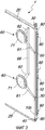
фиг.1 представляет собой вид в перспективе расположения основных частей, которые составляют устройство для установки дверей с боковым втягиванием для единиц мебели или шкафов и т.п. в соответствии с настоящим изобретением;figure 1 is a perspective view of the location of the main parts that make up the device for installing doors with lateral retraction for units of furniture or cabinets, etc. in accordance with the present invention;
фиг.2 представляет собой вид в перспективе того же самого устройства, что и на фиг.1, изображенный с противоположной стороны;figure 2 is a perspective view of the same device as in figure 1, depicted from the opposite side;
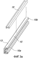
фиг.3а представляет собой вид в перспективе стойки и ее профиля, который может быть присоединен для того, чтобы выполнить петлевую подвеску двери для устройства по фиг.1 и 2, для удобства изображения показанного в горизонтальном положении;figa is a perspective view of the rack and its profile, which can be attached in order to perform a hinge door suspension for the device of figures 1 and 2, for the convenience of the image shown in a horizontal position;
фиг.3b представляет собой увеличенный частичный вид в перспективе элемента фиг.3а;fig.3b is an enlarged partial perspective view of the element figa;
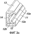
фиг.3с представляет собой увеличенный частичный вид в перспективе элемента фиг.3b;figs is an enlarged partial perspective view of the element of fig.3b;
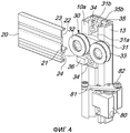
фиг.4 представляет собой частичный в масштабном увеличении и деталировочный вид в перспективе элементов, которые составляют верхнюю часть устройства по фиг.1 и 2;figure 4 is a partial scaled-up and detail perspective view of the elements that make up the upper part of the device of figures 1 and 2;
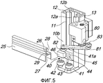
фиг.5 представляет собой частичный в масштабном увеличении и деталировочный вид в перспективе элементов, которые составляют нижнюю часть устройства по фиг.1 и 2;figure 5 is a partial scaled-up and detail perspective view of the elements that make up the lower part of the device of figures 1 and 2;
фиг.6 представляет собой частичный в масштабном увеличении и деталировочный вид в перспективе элементов, которые составляют центральную часть устройства по фиг.1 и 2;6 is a partial enlarged and detailed perspective view of the elements that make up the central part of the device of figures 1 and 2;
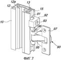
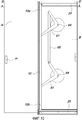
фиг.7 представляет собой частичный в масштабном увеличении и деталировочный вид в перспективе крепления петель профиля по фиг.3;Fig.7 is a partial scaled-up and detail perspective view of the fastening of the profile hinges of Fig.3;
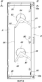
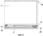
фиг.8 представляет собой вид сбоку устройства по фиг.1 и 2, приложенного к боковой стороне единицы мебели и связанного с краем двери, при этом такая дверь находится в полном убранном положении внутри отсека втягивания, который смежен с полезным внутренним пространством этой единицы мебели, причем и устройство, и дверь показаны вдоль линии сечения VIII-VIII фиг.9;Fig.8 is a side view of the device of Fig.1 and 2, attached to the side of the furniture unit and connected with the edge of the door, while such a door is in the fully retracted position inside the retraction compartment, which is adjacent to the useful interior of this furniture unit, moreover, both the device and the door are shown along the section line VIII-VIII of Fig.9;
фиг.9 представляет собой вид в плане единицы мебели, втягивающейся двери и его скользящего устройства, показанный вдоль линии сечения IX-IX на фиг.8;FIG. 9 is a plan view of a piece of furniture, a retractable door and its sliding device, shown along section line IX-IX in FIG. 8;
фиг.10 представляет собой вид сбоку устройства по фиг.1 и 2, приложенного к той же самой боковой стороне единицы мебели по фиг.8, при этом единица мебели показана с дверью, полностью выдвинутой из своего отсека втягивания или вводимой вдоль линии сечения Х-Х на фиг.11;FIG. 10 is a side view of the device of FIGS. 1 and 2 applied to the same side of the furniture unit of FIG. 8, wherein the furniture unit is shown with a door fully extended from its retraction compartment or introduced along the X- section line X in FIG. 11;
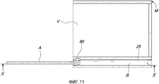
фиг.11 представляет собой вид в плане единицы мебели и устройства по фиг.10, выполненный вдоль его линии сечения XI-XI;11 is a plan view of a piece of furniture and the device of FIG. 10, made along its section line XI-XI;
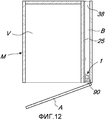
фиг.12 представляет собой вид в плане единицы мебели и устройства по фиг.11 в увеличенной форме и с дверью, уже вытянутой из своего отсека втягивания, показанной на этапе частичного поворотного закрывания во внутреннее пространство единицы мебели;FIG. 12 is a plan view of the furniture unit and the device of FIG. 11 in an enlarged form and with a door already extended from its retraction compartment shown in the partial rotary closing step to the interior of the furniture unit;
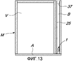
фиг.13 представляет собой вид в плане единицы мебели и устройства по фиг.12, показанной в положении полного закрытия двери в ее полезное внутреннее пространство;Fig.13 is a plan view of a piece of furniture and the device of Fig.12 shown in the fully closed position of the door to its usable interior space;
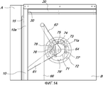
фиг.14 представляет собой частичный в масштабном увеличении вертикальный вид единицы мебели и устройства по фиг.10, иллюстрирующий возможность применения системы для демпфирования скользящего движения двери, показанный в положении демпфирования на последнем этапе вытягивания или на начальном этапе ввода двери в ее отсек втягивания;Fig. 14 is a partial enlarged vertical view of the furniture unit and device of Fig. 10, illustrating the possibility of using the system for damping the sliding movement of the door, shown in the damping position at the last pulling step or at the initial step of entering the door into its pulling compartment;
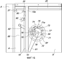
фиг.15 представляет собой вертикальный в масштабном увеличении частичный вид единицы мебели и устройства по фиг.14, показанный в промежуточном положении приема двери в ее отсек втягивания с системой демпфирования в положении максимального противодействия;FIG. 15 is a partial enlarged vertical view of a piece of furniture and the apparatus of FIG. 14, shown in an intermediate position for receiving a door in its retraction compartment with a damping system in a maximum reaction position;
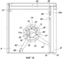
фиг.16 представляет собой вертикальный частичный и увеличенный в масштабе вид единицы мебели и устройства по фиг.14 и 15, показанной в положении полного приема двери в ее отсек втягивания с системой демпфирования, показанной на конечном этапе активизации.FIG. 16 is a vertical partial and enlarged view of a piece of furniture and the apparatus of FIGS. 14 and 15 shown in the fully received position of the door in its retraction compartment with the damping system shown in the final activation step.
Способы исполнения изобретенияMethods of carrying out the invention
На всех чертежах одни и те же детали представлены или понимается, что должны быть представлены одними и теми же ссылочными позициями.In all the drawings, the same details are presented or it is understood that they should be represented by the same reference numbers.
Обращаясь конкретно к фиг.1, 2, 3а, 3b и 3с, можно видеть, что рассматриваемое устройство 1 составлено из стойки 10, образованной профилем, в которой верхний конец 10а и нижний конец 10b выполнены с возможностью скольжения вдоль соответствующих профильных направляющих 20 и 25, которые горизонтально зафиксированы на внешней поверхности стороны внутреннего пространства V, к которой должна быть приложена сдвижная дверь А. Рассматриваемые сдвижная дверь А и устройство 1 могут вмещаться с обеспечением преимущества в отсек В втягивания, который смежен с полезным внутренним пространством V единицы мебели М и завершается внешней стеной с потолком и основанием этой же единицы мебели.Referring specifically to FIGS. 1, 2, 3a, 3b and 3c, it can be seen that the
Более подробно стойка или профиль 10 имеет его внешний продольный паз 11 с продольной впадиной, которая имеет полукружное поперечное сечение 12, и внутренний продольный паз 12а в дополнение к его боковому плечу 13, которое является Т-образным. Профиль 10, кроме того, оснащен стенкой или продольной перегородкой 14, которая образует промежуточную полость 12b, которая вследствие наличия продольного паза 12а открыта в сторону полукружной впадины 12.In more detail, the strut or
Плечо 13 стойки 10 предназначено для приема в себя внутренней полости 15а профиля 15, который выполнен с длиной, несколько более короткой, чем длина стойки 10, и имеет двойную С-образную форму, имеющую полость 15b, которая расположена напротив полости 15а и предназначена для приема в себя оснований нескольких петель 90, что далее будет описано более подробно.The
Полость 15а профиля 15 предназначена для приема в себя плеча 13 стойки 10 после продольного скольжения для того, чтобы быть отрегулированной и запертой по отношению к ней в осевом и в поперечном направлении в соответствии с одним из уже известных способов, изображенных в качестве примера на фиг.3 с фиксирующим посадочным местом 16.The
Как уже упоминалось выше, стойка 10 выполнена с возможностью скольжения вдоль направляющих 20 и 25 посредством установки соответственно верхней каретки 30 и нижней каретки 40, которые должным образом зафиксированы по своим концам соответственно 10а и 10b.As mentioned above, the
Обратимся к фиг.4 - верхняя каретка 30 образована пластиной 31, предназначенной для удержания пары бесприводных роликов 32, 33, причем пластина 31 оснащена короткой планкой 31а с пластиной 31b основания, на которой пара винтов 34 установлена так, что они могут проходить и выполнены с возможностью ввинчиваться в резьбовое посадочное место по меньшей мере одной опорной пластины 35. Эта опорная пластина 35 размещена в полости 12b конца 10а стойки 10 и предпочтительно оснащена плечиками 35b, которые сконфигурированы, чтобы направляться внутри полости 12b стойки 10. Поэтому завинчивание винтов 34 позволяет производить идеальное запирание каретки в правильном положении конца 10а стойки 10, причем такое положение определяется головным плечом опорной пластины 35.Referring to Fig. 4, the
Каретка 30 естественным образом входит в верхнюю направляющую 20, содержащую вдоль бортика 21 пазы для роликов 32, 33, таким образом, что она получает возможность скольжения вдоль полости 22 верхней направляющей 20, которая, кроме того, в присутствии ее перпендикулярной верхней кромки 23 препятствует ее боковому уходу.The
Наконец, верхняя направляющая 20 оснащена нижней полостью 24, которая делает возможным прохождение блока 36 ограничения хода, который предназначен, чтобы упираться в отрегулированный упор 37 с тем, чтобы определить точку остановки каретки 30 и тем самым стойки 10 и двери А в передней части отсека В втягивания.Finally, the
Вблизи верхнего конца 10а и нижнего конца 10b, то есть предпочтительно поблизости от кареток 30 и 40, стойка 10 оснащена также парой устройств 80 для предотвращения втягивания двери А в отсек В, которые активизируются самой дверью А, которая воздействует на круговую резиновую бобышку 83 упругого рычага 81, на противоположный конец которого насажен ролик 82. Во время вращения двери А для ее поворотного закрывания во внутреннее пространство V ролики 82 толкаются в боковом направлении в полость, которая обеспечена в поверхности плеча единицы мебели М, чтобы предотвратить нежелательную реакцию стойки 10 внутрь отсека В втягивания. Когда дверь А находится на начальном этапе ее приема в отсек В втягивания, резиновая бобышка 83 скользит вдоль поверхности двери А, поворачивая рычаг 81 до тех пор, пока ролик 82 не будет вынужден выйти из своего посадочного места, и рабочий ход двери А внутри отсека В разблокируется в соответствии с известным способом и как в качестве примера изображено на фиг.5.Near the
Вновь со ссылкой на фиг.5 - нижняя каретка 40 образована пластиной 41, предназначенной для удержания пары свободных роликов 42, 43, причем пластина 41 оснащена, по существу, перпендикулярной короткой планкой 41а, которая расположена в полости 12b стойки 10 и соединена посредством по меньшей мере одного винта 44 с внешней опорной пластиной 45, которая размещена в полости 11 стойки 10 для правильного крепления каретки 40 на ее конце 10b.Again with reference to FIG. 5, the
Нижняя каретка 40 естественным образом входит в нижнюю направляющую 25, принимающую вдоль направляющего посадочного места 27 ее ролики 42, 43, что делает возможным ее рабочий ход по глубине внутри отсека В втягивания.The
Наконец, нижняя направляющая 25 оснащена верхней полостью 28, которая делает возможным прохождение блока 46 ограничения хода, который приспособлен, чтобы упираться в упор 37 с тем, чтобы определить точку остановки каретки 40 и тем самым стойки 10 и двери А в заднем конце отсека В втягивания. Вблизи нижнего конца 10b предусмотрено устройство 80 для предотвращения возврата двери А в отсек В, как указано выше.Finally, the
Конечно, позиционирование и запирание кареток 30, 40 по концам 10а, 10b стойки 10 позволяет достигать идеально параллельной конфигурации во время хода кареток 30, 40 вдоль соответствующих направляющих 20, 25 в любой момент их движения или позиционирование двери А внутри отсека В втягивания.Of course, the positioning and locking of the
Со ссылками на различные фиг.1-6 - полуцилиндрическая полость 12 стойки 10 предназначена для того, чтобы вмещать в себя пару бесприводных кольцевых колес 52, 53 двух кареток 50, которые введены в нее в промежуточной части стойки 10 до установки и крепления описанных ранее верхней каретки 30 и(или) нижней каретки 40. Промежуточные каретки 50 предназначены для обеспечения динамической связи стойки 10, а значит, и двери А, целиком подвешенной к ней на петлях, с соответствующим концом рычага 61 пары кулис 60, которые далее будут описаны более подробно.With reference to the various figures 1-6, the
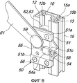
В частности, со ссылкой на фиг.6 промежуточная каретка 50 образована по существу пластиной 51, которая посредством специальных осей (не показаны) приспособлена для удержания пары бесприводных колес 52, 53, которые введены в полуцилиндрическую полость 12 стойки 10, в то время как в ней направляется упорная пластина 54 и удерживается парой боковых направляющих 51а, 51b, которые соединены с пластиной 51 основания, например, посредством четырех винтов 56. К упорной пластине 54 как целый элемент подсоединен осевой штифт 59 и через возможное наложение подшипников или втулок производит петлевое крепление конца рычага 61 кулисы 60.In particular, with reference to FIG. 6, the
Упорная пластина 54 оснащена гайкой или резьбовым выступом 54а, в который ввернут стержень винта 58, головка которого находится в полости 51с пластины 51 основания.The
Вращением винта 58 упорная пластина 54 приводится в поступательное перемещение вдоль направляющих 51а, 51b с последующим поперечным движением осевого штифта 59 и конца рычага 61 кулисы 60. Таким образом, воздействием на винт 58 по меньшей мере одной из кареток 50 можно регулировать и устойчиво фиксировать идеальную вертикальность двери А и ее стойки 10 как во время ее втягивания в отсек В, так и во время ее поворотного закрывания в полезное внутреннее пространство V единицы мебели М. Минимальная и максимальная длина хода упорной пластины 54 определена собачкой (не показана), которая выполнена как единое целое с пластиной 51 и может скользить внутри паза (55) этой упорной пластины 54.By rotation of the
Обратимся, в частности, к фиг.1 и 2, со стойкой 10 посредством соответствующего количества кареток 50 связана пара кулис 60. Каждая кулиса 60 образована не только рычагом 61 для возвратно-поворотного соединения, которое может передаваться в вертикальном направлении на стойку 10 посредством установки соответствующей каретки 50, но также и вторым рычагом 62, который жестко соединен с другим рычагом 61, в положении, которое, например, перпендикулярно, и оснащен своим собственным осевым возвратно-поворотным штифтом 64.Referring in particular to FIGS. 1 and 2, a pair of
В соответствии с решением, которое показано в качестве примера также и на фиг.8 и 10 и 14-16, рычаги 61 и 62 каждой кулисы 60 предпочтительно приварены или в любом случае устойчиво подсоединены к диску 63, который коаксиален с осевым штифтом 64 и предназначен для возможного применения устройства для смягчения движения открывания и закрывания сдвижной двери, как более подробно пояснено далее.In accordance with the solution, which is also shown by way of example in FIGS. 8 and 10 and 14-16, the
В любом случае в соответствии с решением, показанным на сопроводительных чертежах, осевой штифт 64 обеих кулис 60 устойчиво связан с внешней поверхностью плеча единицы мебели, которое уже несет на себе направляющие 20, 25 по глубине внутри отсека В втягивания, разрешая, например, посредством специальных втулок или подшипников (не показаны) возвратно-поворотное перемещение кулис 60.In any case, in accordance with the solution shown in the accompanying drawings, the
В свою очередь, рычаги 62 двух кулис 60 взаимно соединены и поворачиваются посредством распределительной тяги 66, которая обеспечивает их синхронизованное возвратно-поворотное движение относительно позиционирующего и толкательного или тянущего перемещения стойки 10 двери А вдоль направляющих 20 и 25 внутри отсека В втягивания.In turn, the
Как уже упоминалось выше, сдвижная дверь или створка А устойчиво связана со стойкой 10 и поворотно подвешена на ней посредством ввода участка профиля 15, которому придана двойная С-образная форма, как это показано, в частности, на фиг.3, и внутренняя полость 15а которого после соответствующей настройки и запирания 16 принимает в себя крестообразный элемент профиля 13 стойки 10.As mentioned above, the sliding door or sash A is stably connected to the
Обращаясь, в частности, к фиг.7, внешняя полость 15b участка профиля 15 предназначена для приема в себя основания 91 нескольких петель 90, каждая из которых заперта в выбранном вертикальном положении на профиле 15 с закрыванием и запиранием по меньшей мере одного блока 92 посредством по меньшей мере одного винта 93 к внешней поверхности, которая уже сделана как единое целое со стойкой 10.Turning in particular to FIG. 7, the
Описав таким образом основные части рассматриваемого устройства и их промежуточное расположение между плечом единицы мебели и краем сдвижной двери или створки А внутри отсека В втягивания единицы мебели, далее с помощью, в частности, фиг.8-13 будет суммирована их работа, в том числе с точки зрения соответствия указанной цели и задачам изобретения.Having thus described the main parts of the device in question and their intermediate location between the arm of the furniture unit and the edge of the sliding door or sash A inside the compartment B for retracting the furniture unit, then using, in particular, FIGS. 8-13, their work will be summarized, including the point of view of compliance with the specified goals and objectives of the invention.
Обратимся к фиг.8 и 9, на них показана дверь А для закрывания внутреннего пространства V единицы мебели М в полностью втянутом внутрь отсека В единицы мебели положении, чтобы оставить полезное внутреннее пространство V полностью открытым и доступным, будучи направляемой и удерживаемой в этом положении рассматриваемым устройством 1.Referring to Figs. 8 and 9, they show door A for closing the interior space V of the furniture unit M in the fully retracted position inside the compartment B of the furniture unit to leave the useful interior space V fully open and accessible, being guided and held in this position under
Во втянутом положении стойка 10 расположена в заднем конце отсека В, поддерживаемая и направляемая вертикально ее головными каретками 30, 40, которые скользят вдоль соответствующих направляющих 20, 25 и, в свою очередь, поддерживают дверь А посредством нескольких петель 90. Устойчивое удержание двери А в этом положении полной втянутости внутрь отсека В обеспечивается наличием двух рычагов 61 двух кулис 60, которые посредством соответствующих кареток 50 могут перемещаться вдоль стойки 10, при этом их вторые рычаги 62, соединенные тягой 66, синхронизированы с возвратно-поворотным движением кулис 60, сохраняя вертикальность стойки 10 и, следовательно, двери А все время в процессе ее поступательного перемещения и позиционирования.In the retracted position, the
Обратимся к фиг.10 и 11, как уже упоминалось, на них показан момент максимального выдвижения двери А из отсека В втягивания единицы мебели М, например, воздействием руки на ручку m в виде углубления. При выдвижении двери А, конечно, происходит одновременное выдвижение стойки 10, которая скольжением вдоль направляющих 20, 25 входит в зацепление с рычагами 61 двух кулис 60 таким образом, что поворачивает их по осевым штифтам 64. Действительно, поскольку осевой штифт 64 кулис 60 скреплен в одно целое с той же самой стенкой, которая несет направляющие 20, 25, то поступательное движение стойки 10 вызывает поворот рычагов 61 двух кулис 60, причем этот поворот облегчается установкой кареток 50 между концами рычагов 61 и стойкой 10. Посредством кареток 50 все еще можно сделать так, чтобы рычаги 61 могли возвратно-поступательно перемещаться вдоль стойки 10.Turning to FIGS. 10 and 11, as already mentioned, they show the moment of maximum extension of door A from compartment B of the retraction of furniture unit M, for example, by the action of a hand on the handle m in the form of a recess. When the door A is pulled out, of course, the
Поворот рычагов 61, конечно, влечет за собой также и вращение перпендикулярных рычагов 62 двух соответствующих кулис 60, причем эти повороты обязательно синхронизированы вследствие наличия распределительной тяги 66, которая шарнирно соединена с рычагами 62.The rotation of the
Если в рассматриваемом устройстве 1 тяга 62 отсутствует, то при появлении случайного препятствия во время вытягивания двери А или при неравномерном ее вытягивании два рычага 61 будут поворачиваться таким образом, что они будут несинхронизованы и непараллельны, с изменением их расстояния или межцентрового расстояния вдоль стойки 10, так что эта дверь А при этом может быть вытянута, будучи наклоненной, с сохранением отсутствия вертикальности относительно единицы мебели М.If there is no
На самом деле, значение распределительной тяги 66 заключается в том, чтобы обеспечивать идеальное равновесие двери А и ее стойки 10, перенося на стойку не только "консольный" вес самой двери А, но и неравномерность вытягивающего или толкающего движения t двери А, движущейся внутри отсека В.In fact, the significance of the
В показанном до сих пор в качестве примера конструктивном решении приложенное к боковому плечу двери А устройство 1 позволяет лучшее использование глубины внутреннего пространства V, чем во всех других известных решениях. Вследствие этих конструктивных и функциональных особенностей рассматриваемое устройство 1 позволяет использовать в единице мебели М сдвижные двери А, которые выполнены в виде одного полотна, даже если оно значительного размера и веса, без необходимости выполнения их складывающимися, так, чтобы они могли войти в отсек В втягивания просто и безопасно, в соответствии с указанной целью изобретения.In the structural solution shown so far as an example, the
Наличие пары кулис 60, которые "работают" совместно со стойкой 10 для поддержки и уравновешивания поступательного движения двери А в отсек В втягивания, делает это перемещение чрезвычайно легким и тихим в соответствии с другой из указанных задач.The presence of a pair of backstage 60, which "work" together with the
Обращаясь к фиг.12 и 13, становится очевидным тот факт, что по окончании этапа полного вытягивания двери А из отсека В втягивания каретки 30 и 40 стойки 10 оказываются блокированными на внешнем пределе направляющих 20, 26 вследствие активизации устройства 80 предотвращения возврата.Turning to FIGS. 12 and 13, it becomes apparent that at the end of the step of completely pulling door A from the drawer compartment B, the
Когда стойка 10 расположена на краю отсека В втягивания при том, что основания 91 петель 90 "намертво" скреплены с профилем 15 стойки 10, двойная пара подвижных рычагов 95, 96 петель 90, то есть их фиксирующие основания 97, выступают относительно края отсека В втягивания, делая возможным вращательное движение двери А до тех пор, пока не достигается какое-либо ее промежуточное положение по фиг.12 и ее полное поворотное закрывание по фиг.13.When the
Фиг.12 и 13 показывают, что несколько петель 90, предпочтительно установленные на единице мебели М, являются петлями двойного рычажного 95, 96 типа, в результате чего, когда дверь А полностью закрыта, эта дверь А может быть наложена на плечи боковых стоек единицы мебели М, обеспечивая их визуальное укрытие, со значительным эстетическим и визуальным преимуществом, в дополнение к возможности обеспечения максимальной протяженности полезного объема единицы мебели М в соответствии с другой из указанных задач.12 and 13 show that several hinges 90, preferably mounted on furniture unit M, are type
В соответствии с первым конструктивным изменением настоящего устройства для установки дверей, втягиваемых в боковом направлении, устройство 1 вместо того, чтобы устанавливаться на внешней поверхности стенки полезного внутреннего пространства V, может быть установлено на внутренней поверхности внешней стенки отсека В втягивания, с установкой, таким образом, на этой поверхности направляющих 20, 25 и осевого штифта 64 кулис 60 в дополнение к возможной коробке 72 вышеупомянутой демпфирующей системы, более подробно описанной далее.According to a first structural change of the present apparatus for installing laterally retractable doors,
Обратимся, в частности, к фиг.14, 15 и 16, на них, как уже упоминалось, "невидимыми" линиями показан частичный вид спереди предпочтительного применения системы 70 для демпфирования поступательного движения двери и ее стойки 10 внутри отсека В втягивания.Referring in particular to FIGS. 14, 15 and 16, they, as already mentioned, with “invisible” lines show a partial front view of the preferred use of the system 70 for damping the translational movement of the door and its
Более подробно со ссылками также на фиг.1 и 2 внутренняя сторона диска 63 по меньшей мере одной кулисы 60 обеспечена с фасонной поверхностью 71, которая имеет форму кулачка и удобно ориентирована по отношению к положению рычагов 61, 62 кулисы 60.In more detail with reference also to FIGS. 1 and 2, the inner side of the
Диск или крышка 63 выполнена с возможностью поворота на выступающем краю коробки 72, которая прикреплена к той же самой внешней поверхности внутреннего полезного пространства единицы мебели М, к которой прикреплены также направляющие 20, 25, а внизу которой установлен осевой штифт 64 для поворота каждой кулисы 60.The disk or cover 63 is rotatable on the protruding edge of the
На дне коробки 72 жестко прикреплен осевой штифт 73, а также с возможностью поворота насажен конец плеча 74, причем это плечо оснащено щуповым роликом 75, а противоположный конец соединен с концом одного или с большим количеством упругих средств 76, чей противоположный конец выполнен как целое с дном коробки 72. Вследствие силы натяжения упругих средств 76 щуп 75 постоянно находится в контакте с кулачковоподобным профилем 71 крышки 63 кулисы 60.At the bottom of the
Основание коробки 72 оснащено также несколькими демпферами или управляемыми давлением масляными тормозными устройствами 77, которые по-разному воздействуют на несколько секторов круговых зубчатых реек 78, которые расположены в соответствующих положениях захвата.The base of the
Обратимся конкретно к фиг.14, на ней показано положение, при котором стойка 10 расположена в конце отсека В втягивания, а кулачок 71 диска или крышки 63 имеет поверхность 71а максимального эксцентриситета, которая расположена до точки контакта щупа 75 с упругим средством 76, которые реагируют на вход двери в отсек В втягивания, в то время как сцепление демпферов 77 с зубчатыми рейками 78 ни на что не влияет, поскольку они имеют единственное направление вращения, в котором они выполняют свою демпфирующую функцию.Referring specifically to FIG. 14, it shows the position where the
Обратимся к фиг.15, на ней показано положение, в котором поверхность 71а максимального эксцентриситета кулачка 71 выставлена соосно с щупом 75, образуя "мертвую точку" между этапом толкания двери рукой в отсек В и последующим этапом, на котором упругие средства 76 действуют, чтобы затолкнуть двери А в отсек В снова без влияния контакта между демпфером 77 и зубчатыми рейками 78.Referring to FIG. 15, it shows a position in which the
Обратимся к фиг.16, на ней показано положение, в котором поверхность 71а максимального эксцентриситета расположена достаточно далеко от щупа 75, и толкательное действие упругих средств 76 тормозится действием демпферов 77' на зубчатых рейках 78' до момента наведения упора стойки 10 на концевые упоры 38 ограничения хода внутри отсека В.Referring to FIG. 16, it shows a position in which the
Для того чтобы вытянуть дверь А из отсека В, начиная с положения по фиг.16, дверь А вытягивается рукой с постепенной нагрузкой упругих средств 76 вследствие контакта щупа 75 с поднимающейся частью 71а эксцентрикового элемента 71, при этом сцепление демпферов 77' с зубчатыми рейками 78' ни на что не влияет, пока не будет достигнута такая же "мертвая точка", что и на фиг.15.In order to pull door A from compartment B, starting from the position of FIG. 16, door A is pulled by hand with a gradual load of
После того, как "мертвая точка" будут пройдена, упругие средства 76 возвращают накопленное усилие, толкая дверь А в направлении выхода отсека В. На конечном этапе выхода сила тяги упругих средств 76 противоположна воздействию демпферов 77 на зубчатые рейки 78.After the “dead center” has been passed, the elastic means 76 return the accumulated force by pushing the door A in the direction of the compartment B. The traction force of the elastic means 76 is opposite to the action of the
Описания фиг.14, 15 и 16 ясно показывают, что рассматриваемое устройство 1 допускает также положительное использование демпфирующего устройства на этапе ввода двери в отсек В втягивания и вывода из него с тем, чтобы сделать втягивание еще более легким и безопасным в дополнение к дальнейшему увеличению его срока службы во времени в соответствии с еще одной из указанных задач изобретения.The descriptions of FIGS. 14, 15 and 16 clearly show that the
Конечно, только что описанное и проиллюстрированное конструктивное решение устройства 1 может быть изменено и адаптировано под различные условия использования. В качестве примера можно захотеть указать возможность соединения в верхней области двух стенок отсека В втягивания посредством пластины или тонкого ламинированного элемента так, чтобы можно было иметь дверь А, которая могла бы закрывать также и верхний край внутреннего пространства V, имея адекватную высоту отсека В, при одновременном обеспечении адекватной защиты устройства 1 против пыли и делая всю единицу мебели М более прочной.Of course, the just described and illustrated design of the
Далее кулачок 71 и последующую демпфирующую коробку 72 можно установить только на одну из двух кулис 60, и аналогично присутствие демпферов 77, а также кольцевых зубчатых реек 78 может быть исключено, или же они могут быть заменены на другие тормозные системы.Further, the
Более того, можно обеспечить различное угловое отношение между рычагами 61 и 62 кулисами 60, и аналогичным образом можно обеспечить приложение к плечу 13 стойки 10 профиля 15 другого типа, к которому надо будет прикрепить петлю 19 любого типа из обычных петель, оснащенных парами подвижных рычагов 95, 96.Moreover, it is possible to provide a different angular relationship between the
На основе того, что только что было описано и проиллюстрировано, очевидно, что устройство 1 может быть также установлено на дверях А, которые составлены из двух или более створок, которые взаимно соединены и выполнены с возможностью складываться на петлях, с тем, чтобы поместиться в отсеке втягивания, который должен иметь адекватную ширину, и аналогичным образом можно обеспечить установку двух взаимно противоположных втягивающихся дверей по двум сторонам или плечам одной единицы мебели.Based on what has just been described and illustrated, it is obvious that
Понятно, что эти и другие подобные модификации или адаптации в любом случае лежат в объеме новизны настоящего изобретения, защита которого заявлена.It is understood that these and other similar modifications or adaptations in any case lie within the scope of the novelty of the present invention, the protection of which is claimed.
Описание, содержащееся в итальянской патентной заявке № BL2010A000020, на приоритет которой притязает данная патентная заявка, во всей своей полноте включено сюда в качестве ссылки.The description contained in Italian Patent Application No. BL2010A000020, to which this patent application claims priority, is hereby incorporated by reference in its entirety.
Там, где за техническими признаками, упомянутыми в каком-либо пункте формулы изобретения, следуют ссылочные позиции, эти ссылочные позиции были введены исключительно с целью увеличения доступности этих пунктов для понимания, и соответственно такие ссылочные позиции не несут никакого ограничительного эффекта в том, что касается интерпретации каждого элемента, идентифицированного в качестве примера такими ссылочными позициями.Where the technical features mentioned in any claim are followed by reference numerals, these reference numerals have been introduced solely for the purpose of increasing the comprehensibility of these claims, and accordingly, such reference numerals do not have any restrictive effect as regards interpretations of each element identified as an example by such reference numerals.
Claims (16)
- стойку (10), выполненную с возможностью размещения между упомянутой боковой стенкой и краем двери (А) для обеспечения скольжения и поворачивания двери (А);
- продольные направляющие (20, 25), выполненные с возможностью горизонтального крепления на внешней поверхности упомянутой боковой стенки, при этом упомянутая стойка (10) имеет верхний конец (10а) и нижний конец (10b), соединенные с возможностью скольжения с упомянутыми продольными направляющими (20, 25) таким образом, что упомянутая стойка (10) получила возможность скользить в глубине предмета мебели (М), когда устройство (1) установлено в этом предмете мебели (М);
- пару кулис (60), каждая из которых образована парой рычагов (61, 62), которые сходятся между собой и являются цельными друг с другом, причем первый рычаг (61) из упомянутой пары рычагов (61, 62) каждой упомянутой пары кулис (60) является вертикально соединенным с возможностью скольжения с упомянутой стойкой (10), а вторые рычаги (62) упомянутой пары рычагов (61, 62) упомянутой пары кулис (60) являются соединенными друг с другом посредством распределительной тяги (66) нагрузки, и
- соответствующий осевой штифт (64) возвратно-поворотного перемещения для каждой из упомянутой пары кулис (60), выполненный с возможностью поворота как единое целое на упомянутой внешней поверхности упомянутой боковой стенки;1. Device (1) for installing a door (A) with lateral retraction, in particular for a piece of furniture (M), at least between the side wall of the useful interior space (V) of the piece of furniture (M) and its door (A) for so that it is possible to make the door (A) retract laterally during the opening of said interior space, the device (1) comprising:
- a rack (10), made with the possibility of placement between the said side wall and the edge of the door (A) to ensure sliding and rotation of the door (A);
- longitudinal guides (20, 25), made with the possibility of horizontal mounting on the outer surface of the said side wall, while said stand (10) has an upper end (10a) and a lower end (10b), slidingly connected with said longitudinal guides ( 20, 25) in such a way that the counter (10) is able to slide in the depth of the piece of furniture (M) when the device (1) is installed in this piece of furniture (M);
- a pair of wings (60), each of which is formed by a pair of levers (61, 62) that converge with each other and are integral with each other, the first lever (61) of the said pair of levers (61, 62) of each said pair of wings ( 60) is vertically slidably coupled to said strut (10), and second levers (62) of said pair of levers (61, 62) of said pair of wings (60) are connected to each other by a load distribution rod (66), and
- the corresponding axial pin (64) of the reciprocating movement for each of the said pair of wings (60), made with the possibility of rotation as a whole on the said outer surface of the said side wall;
Applications Claiming Priority (3)
| Application Number | Priority Date | Filing Date | Title |
|---|---|---|---|
| ITBL2010A000020A IT1402815B1 (en) | 2010-12-03 | 2010-12-03 | DEVICE FOR THE APPLICATION OF DOORS WITH SIDE DISAPPEARANCE, PARTICULARLY FOR FURNITURE |
| ITBL2010A000020 | 2010-12-03 | ||
| PCT/EP2011/071512 WO2012072738A1 (en) | 2010-12-03 | 2011-12-01 | Device for applying laterally retracting doors, particularly for pieces of furniture |
Publications (2)
| Publication Number | Publication Date |
|---|---|
| RU2013130228A RU2013130228A (en) | 2015-01-10 |
| RU2567717C2 true RU2567717C2 (en) | 2015-11-10 |
Family
ID=43736746
Family Applications (1)
| Application Number | Title | Priority Date | Filing Date |
|---|---|---|---|
| RU2013130228/12A RU2567717C2 (en) | 2010-12-03 | 2011-12-01 | Device for mounting doors with side retraction, particularly for furniture items |
Country Status (9)
| Country | Link |
|---|---|
| US (1) | US9057216B2 (en) |
| EP (1) | EP2655768B1 (en) |
| JP (1) | JP6006728B2 (en) |
| CN (1) | CN103443378B (en) |
| BR (1) | BR112013013053B1 (en) |
| ES (1) | ES2602558T3 (en) |
| IT (1) | IT1402815B1 (en) |
| RU (1) | RU2567717C2 (en) |
| WO (1) | WO2012072738A1 (en) |
Cited By (1)
| Publication number | Priority date | Publication date | Assignee | Title |
|---|---|---|---|---|
| RU2753788C1 (en) * | 2018-05-17 | 2021-08-23 | Кессебёмер Холдинг КГ | Method for rotary fastening of the furniture cover on the body of a piece of furniture by means of the cover fittings |
Families Citing this family (25)
| Publication number | Priority date | Publication date | Assignee | Title |
|---|---|---|---|---|
| US9440727B2 (en) * | 2014-07-11 | 2016-09-13 | B/E Aerospace, Inc. | Telescoping aircraft panel door |
| US9976336B2 (en) * | 2014-07-11 | 2018-05-22 | B/E Aerospace, Inc. | Telescoping aircraft panel door |
| AT516567B1 (en) * | 2014-11-26 | 2018-01-15 | Blum Gmbh Julius | Arrangement of a furniture door and a cavity |
| US9598887B2 (en) * | 2015-02-18 | 2017-03-21 | Margaret B. Reed | Hidden hinge door system and method for use in residential and commercial buildings |
| WO2017066559A1 (en) * | 2015-10-14 | 2017-04-20 | B/E Aerospace, Inc. | Aircraft passenger suite privacy screen control apparatus and method |
| US9894996B1 (en) * | 2016-10-31 | 2018-02-20 | Larry Mitchell Grela | Cabinet |
| AT519246B1 (en) * | 2017-01-13 | 2018-05-15 | Blum Gmbh Julius | Guide system for guiding a movably mounted furniture part |
| AT519515B1 (en) * | 2017-01-13 | 2023-02-15 | Blum Gmbh Julius | facility arrangement |
| DE102017104181A1 (en) * | 2017-02-28 | 2018-08-30 | ambigence GmbH & Co. KG | Furniture |
| DE102017104182A1 (en) * | 2017-02-28 | 2018-08-30 | ambigence GmbH & Co. KG | Furniture |
| AT519903B1 (en) * | 2017-05-11 | 2022-09-15 | Blum Gmbh Julius | Rail for guiding a slide of a furniture door |
| IT201700078326A1 (en) * | 2017-07-12 | 2019-01-12 | Bortoluzzi Sistemi Spa | "FURNITURE WITH SLIDING DOORS AND FOLDABLE DOORS" |
| CN107461097B (en) * | 2017-09-01 | 2022-11-18 | 广东东泰五金精密制造有限公司 | Elastic movable structure of rotating wheel of furniture sliding door |
| CN111406143B (en) * | 2017-11-28 | 2022-03-22 | 博尔托卢齐系统股份公司 | Servo mechanism for furniture leaf |
| CN108060848B (en) * | 2018-01-05 | 2023-08-15 | 广东东泰五金精密制造有限公司 | Furniture rotary opening and closing locking structure |
| DE102018100674B4 (en) * | 2018-01-12 | 2020-03-05 | Hettich-Oni Gmbh & Co. Kg | Furniture plate with a hinge and furniture with such a furniture plate |
| DE102018120661A1 (en) * | 2018-08-23 | 2020-02-27 | ambigence GmbH & Co. KG | Furniture component and manufacturing method |
| AT521133B1 (en) * | 2018-11-14 | 2019-11-15 | Blum Gmbh Julius | Guide system for guiding a movably mounted door leaf |
| AT521365B1 (en) * | 2018-12-20 | 2020-01-15 | Blum Gmbh Julius | Guide system for guiding at least one movably mounted door leaf |
| EP3980619B1 (en) * | 2019-06-07 | 2023-09-13 | Hawa Sliding Solutions AG | Piece of furniture having a door held by a translation device |
| AT17257U1 (en) * | 2019-12-19 | 2021-10-15 | Blum Gmbh Julius | Method for assembling a guide arrangement for a movable furniture part |
| AT523270B1 (en) * | 2019-12-19 | 2021-07-15 | Blum Gmbh Julius | Arrangement for guiding a sliding door or folding sliding door |
| CN111749584A (en) * | 2020-06-19 | 2020-10-09 | 广东威法定制家居股份有限公司 | Side-push hidden door connecting device and storage cabinet |
| AT524324B1 (en) * | 2020-12-17 | 2022-05-15 | Blum Gmbh Julius | Bearing device for bearing at least one door leaf |
| EP4269735A1 (en) * | 2022-03-22 | 2023-11-01 | Griffo, Cristofaro | Double-sided door with integrated universal hinge |
Citations (3)
| Publication number | Priority date | Publication date | Assignee | Title |
|---|---|---|---|---|
| FR2690195A1 (en) * | 1992-04-02 | 1993-10-22 | Bortoluzzi Engineering Srl | Cabinet with folding doors and retractable sliding. |
| DE19902918A1 (en) * | 1998-02-02 | 1999-08-05 | Hawa Ag | Fixture device for foldable door comprising at least two components |
| WO2007148366A1 (en) * | 2006-06-23 | 2007-12-27 | Dada S.P.A. | Cabinet or similar article of furniture with a sliding foldaway door |
Family Cites Families (46)
| Publication number | Priority date | Publication date | Assignee | Title |
|---|---|---|---|---|
| US374859A (en) * | 1887-12-13 | Sliding-door hanger | ||
| US245605A (en) * | 1881-08-16 | Door-hanger | ||
| US423280A (en) * | 1890-03-11 | Door-hanger | ||
| US511208A (en) * | 1893-12-19 | Sliding-door hanger | ||
| US352906A (en) * | 1886-11-23 | James allan | ||
| US863286A (en) * | 1905-07-21 | 1907-08-13 | James L Kershaw | Sectional bookcase. |
| US899049A (en) * | 1908-01-27 | 1908-09-22 | Frederick Joseph Honor | Bookcase. |
| US972412A (en) * | 1909-08-04 | 1910-10-11 | Maurice Taussig | Disappearing door. |
| US984793A (en) * | 1909-10-05 | 1911-02-21 | Frank Olander | Equalizer. |
| US1348680A (en) * | 1918-09-17 | 1920-08-03 | Solomon Himmel | Door-equalizer |
| US1513849A (en) * | 1923-07-25 | 1924-11-04 | Mortimer H Moore | Safe |
| US1720050A (en) * | 1928-03-27 | 1929-07-09 | Grand Rapids Store Equip Co | Disappearing door structure |
| US1930547A (en) * | 1930-06-07 | 1933-10-17 | Lyon Metal Products Inc | Cabinet construction |
| US1909849A (en) * | 1931-03-17 | 1933-05-16 | Remington Rand Inc | Door mounting for safes |
| US1933904A (en) * | 1931-05-16 | 1933-11-07 | Miles W Hawks | Garage door operating mechanism |
| US2632926A (en) * | 1950-08-14 | 1953-03-31 | Dowlong Mfg Co | Sliding door and hardware therefor |
| US2709029A (en) * | 1952-11-12 | 1955-05-24 | Paul F Nockels | Packaging machine for cartons |
| US2774644A (en) * | 1954-02-15 | 1956-12-18 | Ray A Patterson | Drawer and stabilizing means therefor |
| US3359684A (en) * | 1965-08-02 | 1967-12-26 | Dura Corp | Actuator with fixed pivot |
| US3456995A (en) * | 1967-04-11 | 1969-07-22 | Gen Electric | Slide-in cabinet door |
| US3570579A (en) * | 1968-03-18 | 1971-03-16 | Nippon Musical Instruments Mfg | Sliding cover and housing device thereof |
| US3724133A (en) * | 1970-04-03 | 1973-04-03 | Nippon Denso Co | Means for opening and closing a window assembly of a vehicle |
| DE2263073C2 (en) * | 1972-12-22 | 1982-11-25 | Robert Krause KG Zweigniederlassung Weilheim/Teck, 7315 Weilheim | Extension fitting for a first plate and a second plate, such as a table or worktop |
| JPH021427Y2 (en) * | 1981-02-02 | 1990-01-12 | ||
| CH670224A5 (en) * | 1983-04-20 | 1989-05-31 | Cwa Const Sa | |
| JPS6219112A (en) * | 1985-07-19 | 1987-01-27 | 大建工業株式会社 | Receiving apparatus |
| CH670555A5 (en) * | 1986-07-02 | 1989-06-30 | Karl Haab | |
| AT392321B (en) * | 1986-10-16 | 1991-03-11 | Alfit Gmbh | FITTING FOR BOX FURNITURE EQUIPPED WITH SWIVEL-SLIDING DOORS AND THE LIKE |
| US4729612A (en) * | 1987-02-27 | 1988-03-08 | Stone Allen F | Hinge support system |
| US4821375A (en) * | 1988-01-29 | 1989-04-18 | Viking Metal Cabinet Co., Inc. | Recessing hinge mechanism |
| US4976502A (en) * | 1989-04-25 | 1990-12-11 | Herman Miller, Inc. | Cabinet with pocketing doors |
| US5078461A (en) * | 1989-04-25 | 1992-01-07 | Herman Miller, Inc. | Cabinet with pocketing doors |
| DD295975A5 (en) * | 1989-03-14 | 1991-11-21 | Karl Haab Und Otto Haab,Ch | MOEBELSTUECK WITH FASCINABLE DOOR |
| ATE97984T1 (en) * | 1989-03-14 | 1993-12-15 | Karl Haab | PIECE OF FURNITURE WITH RETRACTABLE DOOR. |
| US4974912A (en) * | 1989-04-05 | 1990-12-04 | Standard Precision, Inc. | Pocket door suspension system |
| FR2651530A1 (en) | 1989-09-07 | 1991-03-08 | Azoulay Benjamin | SLIDING DOOR HANGING SUSPENDED. |
| JP2518473Y2 (en) * | 1992-11-18 | 1996-11-27 | 高橋金物株式会社 | Vertical flipper door mounting structure |
| JP2593774Y2 (en) * | 1993-12-29 | 1999-04-12 | スガツネ工業株式会社 | Cabinet with flipper door |
| DE29808185U1 (en) * | 1998-05-06 | 1998-08-27 | Salice Arturo Spa | Furniture with a body part that can be closed by a double-leaf sliding door |
| US6994410B2 (en) * | 2002-09-10 | 2006-02-07 | Knape & Vogt Manufacturing Co. | Pocket door slide |
| DE102005020440A1 (en) | 2005-04-29 | 2006-11-09 | Glasbau Hahn Gmbh + Co. Kg | Display cabinet has door mounted on rollers which slide in C-profile rails at top and bottom, door being mounted on hinges which allow it to swivel so that it rests against side of cabinet when it reaches its end position |
| ITMI20060943A1 (en) | 2006-05-12 | 2007-11-13 | System Holz Spa | NOBODY |
| US20080218043A1 (en) * | 2006-11-15 | 2008-09-11 | Angelo Gianelo | Drawer guidance mechanism |
| US8104850B2 (en) * | 2007-05-30 | 2012-01-31 | Steelcase Inc. | Furniture storage unit |
| PL2246509T3 (en) * | 2009-04-28 | 2013-04-30 | Hawa Ag | Moving device for pivotable partition elements and furniture |
| DE202011002810U1 (en) * | 2011-02-16 | 2011-06-09 | Inter Ikea Systems B.V. | Mechanism for sliding door |
-
2010
- 2010-12-03 IT ITBL2010A000020A patent/IT1402815B1/en active
-
2011
- 2011-12-01 US US13/884,400 patent/US9057216B2/en active Active
- 2011-12-01 WO PCT/EP2011/071512 patent/WO2012072738A1/en active Application Filing
- 2011-12-01 JP JP2013541351A patent/JP6006728B2/en active Active
- 2011-12-01 ES ES11790969.7T patent/ES2602558T3/en active Active
- 2011-12-01 EP EP11790969.7A patent/EP2655768B1/en active Active
- 2011-12-01 RU RU2013130228/12A patent/RU2567717C2/en active
- 2011-12-01 BR BR112013013053A patent/BR112013013053B1/en active IP Right Grant
- 2011-12-01 CN CN201180057854.8A patent/CN103443378B/en active Active
Patent Citations (3)
| Publication number | Priority date | Publication date | Assignee | Title |
|---|---|---|---|---|
| FR2690195A1 (en) * | 1992-04-02 | 1993-10-22 | Bortoluzzi Engineering Srl | Cabinet with folding doors and retractable sliding. |
| DE19902918A1 (en) * | 1998-02-02 | 1999-08-05 | Hawa Ag | Fixture device for foldable door comprising at least two components |
| WO2007148366A1 (en) * | 2006-06-23 | 2007-12-27 | Dada S.P.A. | Cabinet or similar article of furniture with a sliding foldaway door |
Cited By (1)
| Publication number | Priority date | Publication date | Assignee | Title |
|---|---|---|---|---|
| RU2753788C1 (en) * | 2018-05-17 | 2021-08-23 | Кессебёмер Холдинг КГ | Method for rotary fastening of the furniture cover on the body of a piece of furniture by means of the cover fittings |
Also Published As
| Publication number | Publication date |
|---|---|
| BR112013013053B1 (en) | 2020-04-14 |
| ITBL20100020A1 (en) | 2012-06-04 |
| CN103443378A (en) | 2013-12-11 |
| JP2014500417A (en) | 2014-01-09 |
| JP6006728B2 (en) | 2016-10-12 |
| CN103443378B (en) | 2015-09-09 |
| EP2655768B1 (en) | 2016-08-03 |
| ES2602558T3 (en) | 2017-02-21 |
| US9057216B2 (en) | 2015-06-16 |
| WO2012072738A1 (en) | 2012-06-07 |
| US20130232878A1 (en) | 2013-09-12 |
| IT1402815B1 (en) | 2013-09-27 |
| EP2655768A1 (en) | 2013-10-30 |
| BR112013013053A2 (en) | 2016-08-09 |
| RU2013130228A (en) | 2015-01-10 |
Similar Documents
| Publication | Publication Date | Title |
|---|---|---|
| RU2567717C2 (en) | Device for mounting doors with side retraction, particularly for furniture items | |
| JP2014500417A5 (en) | ||
| TWI665372B (en) | Guide system for furniture parts | |
| AU2012261665B2 (en) | Foldable sliding wall and carriage | |
| US8763205B2 (en) | Running gear arrangement having a guide rail for a sliding door | |
| RU2424753C1 (en) | Fittings for corner cabinet with pull-out solid shelf | |
| US20140182212A1 (en) | Device for sliding door leaves with co-planar closure, particularly for furniture and the like | |
| CN207999161U (en) | A kind of adjustable lazy-tongs for furniture push-and-pull opening and closing | |
| RU2547647C2 (en) | Fittings for sliding fold of window or door | |
| CN204920573U (en) | Leading wheel structure and push -and -pull translation door and window | |
| CN201043398Y (en) | Rail sliding frame component used for returning sliding door | |
| CN201363047Y (en) | All-glass frameless hanging manual sliding door | |
| EP2801686B1 (en) | Opening ddevice for coplanar doors | |
| CA2739737A1 (en) | Swinging-sliding door | |
| CN206785224U (en) | A kind of mounting structure of sliding door guide rail and sliding door door leaf | |
| JP2016520742A5 (en) | ||
| JP2016520742A (en) | Functional fitting for sliding doors | |
| RU55838U1 (en) | SLIDING DOOR OR TOP PARTITION PARTITION | |
| CN111749584A (en) | Side-push hidden door connecting device and storage cabinet | |
| KR102364719B1 (en) | Two-way automatic balance door | |
| CN219281528U (en) | Inner pushing door | |
| CN219270503U (en) | Sliding rail supporting wheel for drawer | |
| CN216043426U (en) | Aluminum plate door with sound insulation function | |
| WO2013056865A1 (en) | Aluminum profile structure for door and window frames | |
| CN209510029U (en) | A kind of low-carbon heat-insulating and energy-saving glass sliding door of monoblock type suspended structure |
Legal Events
| Date | Code | Title | Description |
|---|---|---|---|
| PC43 | Official registration of the transfer of the exclusive right without contract for inventions |
Effective date: 20161018 |