EP2654971B1 - Spray booths - Google Patents
Spray booths Download PDFInfo
- Publication number
- EP2654971B1 EP2654971B1 EP11804751.3A EP11804751A EP2654971B1 EP 2654971 B1 EP2654971 B1 EP 2654971B1 EP 11804751 A EP11804751 A EP 11804751A EP 2654971 B1 EP2654971 B1 EP 2654971B1
- Authority
- EP
- European Patent Office
- Prior art keywords
- spray booth
- air
- booth
- roof portion
- work space
- Prior art date
- Legal status (The legal status is an assumption and is not a legal conclusion. Google has not performed a legal analysis and makes no representation as to the accuracy of the status listed.)
- Active
Links
- 239000007921 spray Substances 0.000 title claims description 58
- 238000000605 extraction Methods 0.000 claims description 34
- 238000005507 spraying Methods 0.000 claims description 15
- 239000000463 material Substances 0.000 claims description 8
- 238000009434 installation Methods 0.000 claims description 6
- 238000000034 method Methods 0.000 claims description 6
- 230000008439 repair process Effects 0.000 description 5
- 230000000694 effects Effects 0.000 description 3
- 230000008569 process Effects 0.000 description 3
- 239000011236 particulate material Substances 0.000 description 2
- 238000009423 ventilation Methods 0.000 description 2
- 229910000831 Steel Inorganic materials 0.000 description 1
- 239000011248 coating agent Substances 0.000 description 1
- 238000000576 coating method Methods 0.000 description 1
- 238000010276 construction Methods 0.000 description 1
- 230000008878 coupling Effects 0.000 description 1
- 238000010168 coupling process Methods 0.000 description 1
- 238000005859 coupling reaction Methods 0.000 description 1
- 230000007613 environmental effect Effects 0.000 description 1
- 238000001914 filtration Methods 0.000 description 1
- 238000010438 heat treatment Methods 0.000 description 1
- 238000012986 modification Methods 0.000 description 1
- 230000004048 modification Effects 0.000 description 1
- 238000010422 painting Methods 0.000 description 1
- 239000000843 powder Substances 0.000 description 1
- 239000002904 solvent Substances 0.000 description 1
- 239000010959 steel Substances 0.000 description 1
Images


Classifications
-
- B—PERFORMING OPERATIONS; TRANSPORTING
- B05—SPRAYING OR ATOMISING IN GENERAL; APPLYING FLUENT MATERIALS TO SURFACES, IN GENERAL
- B05B—SPRAYING APPARATUS; ATOMISING APPARATUS; NOZZLES
- B05B16/00—Spray booths
- B05B16/40—Construction elements specially adapted therefor, e.g. floors, walls or ceilings
-
- B—PERFORMING OPERATIONS; TRANSPORTING
- B05—SPRAYING OR ATOMISING IN GENERAL; APPLYING FLUENT MATERIALS TO SURFACES, IN GENERAL
- B05B—SPRAYING APPARATUS; ATOMISING APPARATUS; NOZZLES
- B05B16/00—Spray booths
- B05B16/60—Ventilation arrangements specially adapted therefor
-
- B—PERFORMING OPERATIONS; TRANSPORTING
- B05—SPRAYING OR ATOMISING IN GENERAL; APPLYING FLUENT MATERIALS TO SURFACES, IN GENERAL
- B05B—SPRAYING APPARATUS; ATOMISING APPARATUS; NOZZLES
- B05B14/00—Arrangements for collecting, re-using or eliminating excess spraying material
- B05B14/40—Arrangements for collecting, re-using or eliminating excess spraying material for use in spray booths
- B05B14/43—Arrangements for collecting, re-using or eliminating excess spraying material for use in spray booths by filtering the air charged with excess material
-
- B—PERFORMING OPERATIONS; TRANSPORTING
- B05—SPRAYING OR ATOMISING IN GENERAL; APPLYING FLUENT MATERIALS TO SURFACES, IN GENERAL
- B05B—SPRAYING APPARATUS; ATOMISING APPARATUS; NOZZLES
- B05B16/00—Spray booths
- B05B16/80—Movable spray booths
-
- Y—GENERAL TAGGING OF NEW TECHNOLOGICAL DEVELOPMENTS; GENERAL TAGGING OF CROSS-SECTIONAL TECHNOLOGIES SPANNING OVER SEVERAL SECTIONS OF THE IPC; TECHNICAL SUBJECTS COVERED BY FORMER USPC CROSS-REFERENCE ART COLLECTIONS [XRACs] AND DIGESTS
- Y02—TECHNOLOGIES OR APPLICATIONS FOR MITIGATION OR ADAPTATION AGAINST CLIMATE CHANGE
- Y02B—CLIMATE CHANGE MITIGATION TECHNOLOGIES RELATED TO BUILDINGS, e.g. HOUSING, HOUSE APPLIANCES OR RELATED END-USER APPLICATIONS
- Y02B10/00—Integration of renewable energy sources in buildings
- Y02B10/30—Wind power
-
- Y—GENERAL TAGGING OF NEW TECHNOLOGICAL DEVELOPMENTS; GENERAL TAGGING OF CROSS-SECTIONAL TECHNOLOGIES SPANNING OVER SEVERAL SECTIONS OF THE IPC; TECHNICAL SUBJECTS COVERED BY FORMER USPC CROSS-REFERENCE ART COLLECTIONS [XRACs] AND DIGESTS
- Y02—TECHNOLOGIES OR APPLICATIONS FOR MITIGATION OR ADAPTATION AGAINST CLIMATE CHANGE
- Y02P—CLIMATE CHANGE MITIGATION TECHNOLOGIES IN THE PRODUCTION OR PROCESSING OF GOODS
- Y02P70/00—Climate change mitigation technologies in the production process for final industrial or consumer products
- Y02P70/10—Greenhouse gas [GHG] capture, material saving, heat recovery or other energy efficient measures, e.g. motor control, characterised by manufacturing processes, e.g. for rolling metal or metal working
Definitions
- the present invention relates to spray booths.
- a spray booth is a structure that provides a ventilated, air filtered and temperature controlled environment in which spraying activities such as painting and powder coating can take place.
- a spray booth is necessary for the safe execution of such activities, since the sprayed materials include solvents and particulate material that must not enter the atmosphere in large quantities. The particulate material that does not stick to the article being sprayed must be removed from the spraying area to ensure safe working conditions, and to manage environmental impact.
- a spray booth also provides a controlled supply of filtered air that aids the spraying process and leads to higher quality finishes.
- it is necessary to heat sprayed materials in order to dry them (in a process known as baking), and the spray booth provides a controlled temperature environment in which such baking can be undertaken.
- US2137862 describes a conventional apparatus for providing a controlled environment for spraying of particularly material at a railway carriage.
- the apparatus has open sides so that the booth may be moved along the carriage during the spraying process.
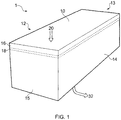
- the spray booth 1 comprises a roof portion 10 from which two pairs 12, 14 and 13, 15 of side portions extend to the ground, thereby forming a closed chamber in which spraying can be carried out.
- One or more of the side portions is movable to allow an object, in this case a car 3, to be located in the chamber for spraying.
- a plenum 16 is formed adjacent the roof 10 by the provision of a filter element 18 substantially parallel to, and spaced from the inner surface of the roof portion.
- the filter element 18 may extend across the whole of the roof portion 10, as illustrated, or may be provided across only a limited area.
- an input air flow 20 is supplied into the plenum 16, after which it passes through the filter 18 and forms an incoming air flow 22.
- the air flow 22 is uniform across the width of the booth.
- the airflow 22 passes around the object 3, and forms an outgoing air flow 24.
- This outgoing airflow 24 passes through an outgoing filter 26, into an extraction area 28, and into an extraction duct 30 which provides an extracted airflow 32.
- the extraction area 28 is provided below the object 3 being sprayed, and typically extends below the ground surface of the location of the spray booth 1.
- the input airflow is provided by air handling equipment, such as that shown for illustrative purposes in Figure 3 of the accompanying drawings.
- the air handling equipment 40 of Figure 3 comprises input ducting 44 which guides air 42 into the equipment from the atmosphere.
- a fan unit 46 is provided for drawing in the air 42, and for moving the air via ducting 47 to a heater 48 which operates to heat the air to a desired temperature.
- the temperature controlled air 20 is then provided to the spray booth via ducting 49.
- Air extraction from the booth 1 is provided by air extraction equipment, such as that shown for illustrative purposes in Figure 4 of the accompanying drawings.
- the extracted airflow 32 is drawn through ducting 50 by an extraction fan unit 52.
- the airflow passes through a further filtration unit 54 before exiting to atmosphere 58 via further ducting 56.
- the spray booth 1 of Figure 1 and 2 and the air handling equipment of Figures 3 and 4 has been described by way of example and illustration only, and it will be readily appreciated that the design and construction of a spray booth can vary.
- the input and output air handling equipment can be combined to reduce the number of fan units and reduce the heating requirements by using recirculation of air.
- a body shop which repairs and repaints cars and other vehicles, may have the need for several spray booths to enable multiple jobs to be carried out at any one time.
- the movement of vehicles in such a body shop can lead to increased work times, and so body shops are starting to use workshop bays for multiple tasks, only one of which is repainting.
- a damaged vehicle may be driven into the workshop and positioned in a repair bay in which a range of actions will be carried out on the vehicle. Damaged mechanical parts may be replaced, and damaged bodywork repaired or replaced. Once this repair work has been carried out, the vehicle must then be transferred to the spray booth for finishing.
- each work area can be equipped as a spray booth, so that, in effect, all repair work is carried out in the controlled environment provided by the booth.
- a spray booth In order to reduce the number of vehicle movement in the workshop, each work area can be equipped as a spray booth, so that, in effect, all repair work is carried out in the controlled environment provided by the booth.
- such a solution is expensive, both in terms of capital cost, and in terms of running costs. Since not all actions require the provision of a controlled environment, such costs are unnecessary.
- a spray booth for providing a controlled environment for spraying of material
- the spray booth comprising a roof portion provided with at least one mounting bracket for attachment to a support rail, such that the booth is movable along such a support rail when in use, first and second end portions which extend from respective opposing ends of the roof portion, first and second side portions which extend from respective opposing sides of the roof portion, thereby defining a work space between the roof portion, the end portions and the side portions, the first and second side portions each defining an opening therethrough, and each including a movable member having a first position in which the opening is closed, and a second position in which the opening is substantially open, and an air extraction unit which extends from the roof portion into the work space, and operable to extract air from the work space, wherein each such movable member extends, in the first position, beyond a lowermost part of at least one of the first and second end portions.
- Such a spray booth may further comprise air input equipment operable to input an airflow into the work space via the roof portion.
- the roof portion may define a plenum into which the airflow is supplied.
- the air extraction unit may comprise a fan unit mounted on the roof portion, extraction ducting extending from the fan unit to inside the work space, and an extraction filter located on the extraction ducting.
- a spray booth may further comprise an air outlet connected with the fan unit, and arranged for connection to an air outlet chimney.
- Such a spray booth may comprise a plurality of such air extraction units, each such unit being connected with the air outlet, in which case the air extraction units may be located in respective corners of the booth.
- the air extraction units may be operable independently of one another.
- a spray booth installation comprising a support rail, and a spray booth in accordance with the first aspect of the present invention, wherein the spray booth is suspended from the support rail so as to be movable along the support rail.
- a method of operating a spray booth according to a first aspect of the present invention or a spray booth installation according to a second aspect of the present invention in which material spraying equipment is enabled only when the or ach air extraction unit is operating.
- an auxiliary electrical supply to the work space may be enabled only when the or each air extraction unit is not operating.
- FIG. 5 illustrates a spray booth 100 which embodies one aspect of the present invention.
- the spray booth, 100 comprises a roof portion 102, from which extends first and second end portions 104 and 106 and first and second side portions, 108 and 110, so as to define an enclosed work space.
- the end portions 104 and 106 are at opposite ends of the spray booth 100, and the side portions 108 and 110 are at opposite sides of the booth 100.
- the roof portion 102, the end portions 104 and 106, and the side portions 108 and 110 define a work space therebetween.
- the first side portion 108 is made up of two partial side portions 108a and 108b, such that the side portion of the spray booth 100 defines an opening.
- a movable side curtain 109 is provided for closing the opening of the side of the booth, as shown in Figure 6 .
- the second side portion 110 is made up of a pair of partial side portions 110a and 110b, and a movable side curtain 111 is provided for closing the opening in the second side.
- the second end portion 106 is provided with an access door 107.
- the roof portion 102 of the booth 100 defines a plenum as with the booth described above, and an air inlet 112 is defined in the roof portion 102.
- the air inlet allows an incoming air flow 114 to enter the plenum, and hence the booth 100.
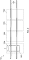
- An air outlet 116 is provided on the roof portion 102 for guiding an expelled airflow 118 from the booth.
- the expelled airflow is provided by at least one air extractor.
- Four such air extractors 120 are illustrated in Figures 5 and 6 , but any number can be provided.
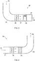
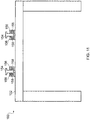
- FIG 7 illustrates a side view of the booth of Figures 5 and 6 , with the side portions and movable curtains removed for the sake of clarity.
- the roof portion 102 defines the plenum therein, and the first and second end portions 104 and 106 extend downwardly from the roof portion 102.
- Associated with each air extractor 120 are an extraction duct 126 and an extraction filter 128, which extend down from the roof portion 102 towards the floor 122.
- the air extractor units operate to draw in air from the booth, through the extraction filter 128 and extraction duct 126.
- the extracted air is then pumped to the air outlet 116, via outlet ducting 130, as illustrated in Figure 8 .
- first and second end portions 104 and 106 of the booth 100 do not reach the ground level 122 when the booth is installed, and a ventilation gap 124 is therefore provided.
- This ventilation gap 124 is provided in order to allow air to be drawn into the booth 100, which is kept at a slightly negative pressure with respect to the air pressure outside the booth 100.
- the movable curtains 109 and 111 for the first and second side portions 108 and 110 can be extended to the ground level (see Figure 6 ), to provide an effective seal, thereby preventing leakage of spray material and air from the sides of the booth.
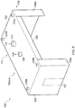
- Figure 9 illustrates mounting of the booth 100 in a workshop environment 150.
- the booth 100 is suspended from a pair of rails 154 which extend across the workshop 150.
- the rails would typically be attached to the walls of the workshop, or suspended themselves from the roof of the workshop.
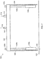
- Figure 10 illustrates schematically the relative positions of the booth 100 and rails 154.
- the workshop 150 defines a series of working areas 152 (in this example four such areas are illustrated, but any number could be provided).
- the support rails 154 extend across the working areas 152, and enable the booth 100 to be moved from one working area to another, in the direction shown by arrow A.
- the movable side curtains 109 and 111 are raised, so as to provide the side openings. These openings allow the booth to move over the vehicles in the working areas, and so to be moved along the rails to the next working area requiring the spray booth. This may be the area next to the existing area, or may be any one of the other areas 152 in the workshop 150.
- the curtain side are closed, and the booth operated.
- Figure 11 illustrates one example of how the booth 100 can be supported on the rails 154.
- the rails 154 in Figure 11 are provided by steel I-beams, as these are a common building component, and are capable of supporting the weight of the spray booth.
- the booth 100 is provided with a series of support brackets 156 which are attached to the roof portion 102 of the booth 100, and which extend around and over lower sections of the I-beam rails.
- the brackets 156 are supported on the rails by bearings 158.
- the booth is provided with four brackets 156 and associated bearings 158. However, it will be readily appreciated that any appropriate number of support brackets and bearings may be provided.
- the air outlet 116 may be connect with an exhaust chimney using flexible ducting or a suitable moving-seal arrangement.
- the air inlet 112 may also be provided with such a movable coupling.
- the spray booth embodying the present invention is preferably delivered to the installation site in the form of a kit of parts, which are then assembled.
- the kit of parts would include a roof frame, panels for the roof portion 102, end portions 104 and 106 and side portions 108.
- the movable curtains 109 and 111, the air input and extraction equipment and other sundry equipment is delivered to site for installation on/in the booth.
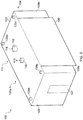
- the plenum of the booth 100 embodying the present invention can be divided into a number of sub-plenum areas, so that airflow in the booth can be controlled.
- the air extraction units can be independently controlled in order to enhance this airflow control.
- Figure 12 illustrates a situation in which all of the air extraction unit 120 are operational and all areas of the plenum are operational. Such a situation results in a full airflow 160 across the whole of the work space of the booth 100.
- Figure 13 illustrates a situation in which the air extraction units 120a and 120b and one end of the booth 100 are operational, together with the appropriate part of the plenum, such that an airflow 162 is provided only in a desired part of the work space. It will be readily appreciated that this independent control of air extraction units, and plenum areas, enables the operator of the booth to run only the air handling equipment required by each job. For example, a repair to only a small portion of a vehicle may not require full spray booth operation.
Landscapes
- Details Or Accessories Of Spraying Plant Or Apparatus (AREA)
Priority Applications (1)
| Application Number | Priority Date | Filing Date | Title |
|---|---|---|---|
| PL11804751T PL2654971T3 (pl) | 2010-12-23 | 2011-12-09 | Kabiny natryskowe |
Applications Claiming Priority (2)
| Application Number | Priority Date | Filing Date | Title |
|---|---|---|---|
| GB1021825.3A GB2486705B (en) | 2010-12-23 | 2010-12-23 | Spray booths |
| PCT/GB2011/052445 WO2012085535A1 (en) | 2010-12-23 | 2011-12-09 | Spray booths |
Publications (2)
| Publication Number | Publication Date |
|---|---|
| EP2654971A1 EP2654971A1 (en) | 2013-10-30 |
| EP2654971B1 true EP2654971B1 (en) | 2019-07-03 |
Family
ID=43598878
Family Applications (1)
| Application Number | Title | Priority Date | Filing Date |
|---|---|---|---|
| EP11804751.3A Active EP2654971B1 (en) | 2010-12-23 | 2011-12-09 | Spray booths |
Country Status (7)
| Country | Link |
|---|---|
| US (1) | US9643203B2 (pl) |
| EP (1) | EP2654971B1 (pl) |
| CN (2) | CN103313799A (pl) |
| AU (1) | AU2011346909B2 (pl) |
| GB (1) | GB2486705B (pl) |
| PL (1) | PL2654971T3 (pl) |
| WO (1) | WO2012085535A1 (pl) |
Families Citing this family (17)
| Publication number | Priority date | Publication date | Assignee | Title |
|---|---|---|---|---|
| CN106931333B (zh) | 2011-11-23 | 2020-11-27 | 夸克星有限责任公司 | 发光装置 |
| US8826565B2 (en) * | 2012-06-14 | 2014-09-09 | Hahn Marketing LLC | Automotive paint spray and drying booth |
| GB2530070B (en) * | 2014-09-12 | 2017-05-17 | Spraybooth Tech Ltd | Workshop installations comprising a spray booth |
| CA2906801C (en) | 2014-10-13 | 2019-12-03 | Salvatore FERRARA | A varnishing plant for body shops |
| US20150167991A1 (en) * | 2015-02-27 | 2015-06-18 | Caterpillar Inc. | Dust containment assembly |
| SE1530144A1 (sv) | 2015-09-29 | 2016-10-11 | Pivab Ab | Work booth safety system for an automotive body repair shop |
| ES2609838B1 (es) * | 2015-10-16 | 2018-02-27 | Roisber Servicios, S.L. | Cabina de trabajo convertible |
| ITUB20160399A1 (it) | 2016-01-21 | 2017-07-21 | Salvatore Ferrara | Impianto di verniciatura, in particolare per carrozzerie |
| CN106000723A (zh) * | 2016-07-05 | 2016-10-12 | 宿州市明兴金属制造有限公司 | 进气缸盖喷漆装置 |
| CN106181691B (zh) * | 2016-07-05 | 2018-08-28 | 宿州市明兴金属制造有限公司 | 进气缸盖加工装置 |
| CN107855239B (zh) * | 2017-11-24 | 2019-04-30 | 重庆冠亨汽车配件有限公司 | 一种汽车小部件喷漆装置 |
| CN108745746B (zh) * | 2018-06-07 | 2021-05-14 | 芜湖众梦电子科技有限公司 | 一种用于汽车外壳喷漆的自动喷绘设备 |
| CN109158246A (zh) * | 2018-10-24 | 2019-01-08 | 安徽柳溪智能装备有限公司 | 一种减振器端面喷涂装置 |
| US10937007B2 (en) * | 2018-11-05 | 2021-03-02 | Rygir Holdings | Electronically tracking vehicle state in a vehicle maintenance facility |
| CN110813618B (zh) * | 2019-11-26 | 2020-12-08 | 阳信东泰精密金属有限公司 | 一种铝合金工件表面处理装置 |
| CN111185334B (zh) * | 2020-01-13 | 2021-05-18 | 扬州市诚信涂装设备有限公司 | 一种用于铝型材表面加工的快速喷涂装置 |
| CN111468330A (zh) * | 2020-04-21 | 2020-07-31 | 江苏益通流体科技有限公司 | 一种旋液分离器用高效性喷涂装置 |
Family Cites Families (27)
| Publication number | Priority date | Publication date | Assignee | Title |
|---|---|---|---|---|
| US1980224A (en) * | 1930-07-19 | 1934-11-13 | Jens A Paasche | Exhaust system |
| US2137862A (en) * | 1937-01-28 | 1938-11-22 | Carleton K Steins | Fume exhausting apparatus |
| GB706600A (en) * | 1951-04-19 | 1954-03-31 | Devilbiss Co | Travelling spray booth |
| US2761373A (en) * | 1951-04-19 | 1956-09-04 | Vilbiss Co | Traveling spray booth |
| US2829582A (en) * | 1954-01-18 | 1958-04-08 | Lockheed Aircraft Corp | Apparatus useful in painting aircraft |
| US4231289A (en) * | 1979-01-26 | 1980-11-04 | Alain Domicent | Painting booth |
| US4237780A (en) * | 1979-01-30 | 1980-12-09 | Andrew Truhan | Hydrocarbon fume disposal system particularly for use in paint spray booths |
| US4590847A (en) * | 1982-12-29 | 1986-05-27 | Hull Francis R | Supply make-up air attachment for exhaust booths |
| US4714010A (en) * | 1985-04-12 | 1987-12-22 | Cm & E/California, Inc. | Industrial exhaust ventilation system |
| JPH03123652A (ja) * | 1989-10-05 | 1991-05-27 | Taikisha Ltd | 塗装設備 |
| US5042420A (en) * | 1989-11-27 | 1991-08-27 | Binks Manufacturing Company | Trapezoidal painting structure |
| US5063835A (en) * | 1990-06-15 | 1991-11-12 | Plaatwerkerij D.W. Slotboom B.V. | Processing booth with variable ventilation |
| US5228621A (en) * | 1991-10-04 | 1993-07-20 | The United States, As Represented By The Secretary Of Agriculture | Apparatus and method for applying material to agricultural commodities |
| US5277652A (en) * | 1993-02-23 | 1994-01-11 | Minor James G | Spray booth |
| US5456023A (en) * | 1994-06-28 | 1995-10-10 | Ransburg Corporation | Advance cure paint spray booth |
| US5749779A (en) * | 1995-11-09 | 1998-05-12 | Wilburn's Body Shop, Inc. | Movable overhead ventilation assembly and filtering method |
| US5864991A (en) * | 1998-01-02 | 1999-02-02 | Burns; Gary | Mobile booth system |
| SE512940C2 (sv) * | 1998-10-07 | 2000-06-12 | Plymovent Ab | Utsugningsanläggning med en drivbar löpvagn och en till ett viloläge uppdragbar slang |
| EP1120168A1 (en) * | 2000-01-28 | 2001-08-01 | Smart Car Centres Ltd. | Vehicle painting enclosure |
| US6334578B1 (en) * | 2000-11-20 | 2002-01-01 | John L. House | Spray hood assembly |
| DE10209489B4 (de) * | 2002-03-05 | 2010-06-02 | Eisenmann Anlagenbau Gmbh & Co. Kg | Kabine zur Beschichtung von Gegenständen mit Pulver |
| CN2705238Y (zh) * | 2004-05-11 | 2005-06-22 | 高军 | 一种活动喷漆室 |
| US7798547B2 (en) * | 2005-08-04 | 2010-09-21 | Antaya Bruce C | Portable paint booth |
| US20070160768A1 (en) * | 2005-10-12 | 2007-07-12 | High Impact Technology, L.L.C. | Pipeline-straddling protective barrier coating |
| CN201120353Y (zh) * | 2007-10-31 | 2008-09-24 | 机械工业第六设计研究院 | 桥式移动送风水旋喷烘两用喷漆室 |
| CN201200948Y (zh) * | 2008-05-23 | 2009-03-04 | 长沙中联重工科技发展股份有限公司 | 移动式喷漆室 |
| EP2248596B1 (de) * | 2009-05-06 | 2012-02-29 | Abb Ag | Anordnung zum Beschichten von Werkstücken |
-
2010
- 2010-12-23 GB GB1021825.3A patent/GB2486705B/en active Active
-
2011
- 2011-12-09 CN CN2011800623825A patent/CN103313799A/zh active Pending
- 2011-12-09 EP EP11804751.3A patent/EP2654971B1/en active Active
- 2011-12-09 CN CN201811011028.XA patent/CN108970885A/zh active Pending
- 2011-12-09 PL PL11804751T patent/PL2654971T3/pl unknown
- 2011-12-09 AU AU2011346909A patent/AU2011346909B2/en active Active
- 2011-12-09 WO PCT/GB2011/052445 patent/WO2012085535A1/en not_active Ceased
- 2011-12-09 US US13/995,756 patent/US9643203B2/en active Active
Non-Patent Citations (1)
| Title |
|---|
| None * |
Also Published As
| Publication number | Publication date |
|---|---|
| EP2654971A1 (en) | 2013-10-30 |
| WO2012085535A1 (en) | 2012-06-28 |
| PL2654971T3 (pl) | 2019-12-31 |
| US9643203B2 (en) | 2017-05-09 |
| GB201021825D0 (en) | 2011-02-02 |
| AU2011346909B2 (en) | 2016-11-10 |
| GB2486705A (en) | 2012-06-27 |
| CN103313799A (zh) | 2013-09-18 |
| AU2011346909A1 (en) | 2013-07-04 |
| CN108970885A (zh) | 2018-12-11 |
| US20130337733A1 (en) | 2013-12-19 |
| GB2486705B (en) | 2013-03-13 |
Similar Documents
| Publication | Publication Date | Title |
|---|---|---|
| EP2654971B1 (en) | Spray booths | |
| US7666077B1 (en) | Paint booth arrangement and method for directing airflow | |
| EP3215279B1 (en) | Work piece spraying and processing arrangements | |
| US4926746A (en) | Work chamber with shifting ventilation zone | |
| JP5302223B2 (ja) | 塗装設備 | |
| JP5202818B2 (ja) | 塗装ブース | |
| US7779779B2 (en) | Spray booth | |
| EP1967804B1 (en) | Drying device and method for painted bodies, and device for circulating drying air in such device and method | |
| US20060243202A1 (en) | Aircraft spray booth | |
| WO2017058075A1 (en) | Work booth safety system for an automotive body repair shop | |
| KR101064919B1 (ko) | 일방향 공기 흐름을 제공하는 도장부스용 도어 | |
| WO2015184324A1 (en) | Directional air apparatuses, systems, and methods of using the same | |
| WO2016038352A1 (en) | Workshop paint installation | |
| EP3009195B1 (en) | A varnishing plant for body shops | |
| GB2487565A (en) | Spray booth with movable guide vanes for controlling the airflow | |
| GB2498295A (en) | Spray booths | |
| GB2487549A (en) | Spray booth with underfloor air extraction ducts | |
| GB2486703A (en) | Spray booth ventilation system with nozzles for blowing air transverse the main airflow | |
| GB2498135A (en) | Spray booth |
Legal Events
| Date | Code | Title | Description |
|---|---|---|---|
| PUAI | Public reference made under article 153(3) epc to a published international application that has entered the european phase |
Free format text: ORIGINAL CODE: 0009012 |
|
| 17P | Request for examination filed |
Effective date: 20130723 |
|
| AK | Designated contracting states |
Kind code of ref document: A1 Designated state(s): AL AT BE BG CH CY CZ DE DK EE ES FI FR GB GR HR HU IE IS IT LI LT LU LV MC MK MT NL NO PL PT RO RS SE SI SK SM TR |
|
| DAX | Request for extension of the european patent (deleted) | ||
| STAA | Information on the status of an ep patent application or granted ep patent |
Free format text: STATUS: EXAMINATION IS IN PROGRESS |
|
| 17Q | First examination report despatched |
Effective date: 20180508 |
|
| RIC1 | Information provided on ipc code assigned before grant |
Ipc: B05B 15/00 20060101AFI20180919BHEP |
|
| REG | Reference to a national code |
Ref country code: DE Ref legal event code: R079 Ref document number: 602011060235 Country of ref document: DE Free format text: PREVIOUS MAIN CLASS: B05B0015120000 Ipc: B05B0016800000 |
|
| GRAP | Despatch of communication of intention to grant a patent |
Free format text: ORIGINAL CODE: EPIDOSNIGR1 |
|
| RIC1 | Information provided on ipc code assigned before grant |
Ipc: B05B 16/60 20180101ALI20181221BHEP Ipc: B05B 16/80 20180101AFI20181221BHEP |
|
| STAA | Information on the status of an ep patent application or granted ep patent |
Free format text: STATUS: GRANT OF PATENT IS INTENDED |
|
| INTG | Intention to grant announced |
Effective date: 20190131 |
|
| GRAS | Grant fee paid |
Free format text: ORIGINAL CODE: EPIDOSNIGR3 |
|
| GRAA | (expected) grant |
Free format text: ORIGINAL CODE: 0009210 |
|
| STAA | Information on the status of an ep patent application or granted ep patent |
Free format text: STATUS: THE PATENT HAS BEEN GRANTED |
|
| AK | Designated contracting states |
Kind code of ref document: B1 Designated state(s): AL AT BE BG CH CY CZ DE DK EE ES FI FR GB GR HR HU IE IS IT LI LT LU LV MC MK MT NL NO PL PT RO RS SE SI SK SM TR |
|
| REG | Reference to a national code |
Ref country code: GB Ref legal event code: FG4D |
|
| REG | Reference to a national code |
Ref country code: CH Ref legal event code: EP Ref country code: AT Ref legal event code: REF Ref document number: 1150332 Country of ref document: AT Kind code of ref document: T Effective date: 20190715 |
|
| REG | Reference to a national code |
Ref country code: IE Ref legal event code: FG4D |
|
| REG | Reference to a national code |
Ref country code: DE Ref legal event code: R096 Ref document number: 602011060235 Country of ref document: DE |
|
| REG | Reference to a national code |
Ref country code: NL Ref legal event code: MP Effective date: 20190703 |
|
| REG | Reference to a national code |
Ref country code: LT Ref legal event code: MG4D |
|
| REG | Reference to a national code |
Ref country code: AT Ref legal event code: MK05 Ref document number: 1150332 Country of ref document: AT Kind code of ref document: T Effective date: 20190703 |
|
| PG25 | Lapsed in a contracting state [announced via postgrant information from national office to epo] |
Ref country code: SE Free format text: LAPSE BECAUSE OF FAILURE TO SUBMIT A TRANSLATION OF THE DESCRIPTION OR TO PAY THE FEE WITHIN THE PRESCRIBED TIME-LIMIT Effective date: 20190703 Ref country code: LT Free format text: LAPSE BECAUSE OF FAILURE TO SUBMIT A TRANSLATION OF THE DESCRIPTION OR TO PAY THE FEE WITHIN THE PRESCRIBED TIME-LIMIT Effective date: 20190703 Ref country code: HR Free format text: LAPSE BECAUSE OF FAILURE TO SUBMIT A TRANSLATION OF THE DESCRIPTION OR TO PAY THE FEE WITHIN THE PRESCRIBED TIME-LIMIT Effective date: 20190703 Ref country code: PT Free format text: LAPSE BECAUSE OF FAILURE TO SUBMIT A TRANSLATION OF THE DESCRIPTION OR TO PAY THE FEE WITHIN THE PRESCRIBED TIME-LIMIT Effective date: 20191104 Ref country code: FI Free format text: LAPSE BECAUSE OF FAILURE TO SUBMIT A TRANSLATION OF THE DESCRIPTION OR TO PAY THE FEE WITHIN THE PRESCRIBED TIME-LIMIT Effective date: 20190703 Ref country code: NO Free format text: LAPSE BECAUSE OF FAILURE TO SUBMIT A TRANSLATION OF THE DESCRIPTION OR TO PAY THE FEE WITHIN THE PRESCRIBED TIME-LIMIT Effective date: 20191003 Ref country code: BG Free format text: LAPSE BECAUSE OF FAILURE TO SUBMIT A TRANSLATION OF THE DESCRIPTION OR TO PAY THE FEE WITHIN THE PRESCRIBED TIME-LIMIT Effective date: 20191003 Ref country code: NL Free format text: LAPSE BECAUSE OF FAILURE TO SUBMIT A TRANSLATION OF THE DESCRIPTION OR TO PAY THE FEE WITHIN THE PRESCRIBED TIME-LIMIT Effective date: 20190703 Ref country code: AT Free format text: LAPSE BECAUSE OF FAILURE TO SUBMIT A TRANSLATION OF THE DESCRIPTION OR TO PAY THE FEE WITHIN THE PRESCRIBED TIME-LIMIT Effective date: 20190703 |
|
| PG25 | Lapsed in a contracting state [announced via postgrant information from national office to epo] |
Ref country code: AL Free format text: LAPSE BECAUSE OF FAILURE TO SUBMIT A TRANSLATION OF THE DESCRIPTION OR TO PAY THE FEE WITHIN THE PRESCRIBED TIME-LIMIT Effective date: 20190703 Ref country code: ES Free format text: LAPSE BECAUSE OF FAILURE TO SUBMIT A TRANSLATION OF THE DESCRIPTION OR TO PAY THE FEE WITHIN THE PRESCRIBED TIME-LIMIT Effective date: 20190703 Ref country code: RS Free format text: LAPSE BECAUSE OF FAILURE TO SUBMIT A TRANSLATION OF THE DESCRIPTION OR TO PAY THE FEE WITHIN THE PRESCRIBED TIME-LIMIT Effective date: 20190703 Ref country code: IS Free format text: LAPSE BECAUSE OF FAILURE TO SUBMIT A TRANSLATION OF THE DESCRIPTION OR TO PAY THE FEE WITHIN THE PRESCRIBED TIME-LIMIT Effective date: 20191103 Ref country code: LV Free format text: LAPSE BECAUSE OF FAILURE TO SUBMIT A TRANSLATION OF THE DESCRIPTION OR TO PAY THE FEE WITHIN THE PRESCRIBED TIME-LIMIT Effective date: 20190703 Ref country code: GR Free format text: LAPSE BECAUSE OF FAILURE TO SUBMIT A TRANSLATION OF THE DESCRIPTION OR TO PAY THE FEE WITHIN THE PRESCRIBED TIME-LIMIT Effective date: 20191004 |
|
| PG25 | Lapsed in a contracting state [announced via postgrant information from national office to epo] |
Ref country code: TR Free format text: LAPSE BECAUSE OF FAILURE TO SUBMIT A TRANSLATION OF THE DESCRIPTION OR TO PAY THE FEE WITHIN THE PRESCRIBED TIME-LIMIT Effective date: 20190703 |
|
| PG25 | Lapsed in a contracting state [announced via postgrant information from national office to epo] |
Ref country code: RO Free format text: LAPSE BECAUSE OF FAILURE TO SUBMIT A TRANSLATION OF THE DESCRIPTION OR TO PAY THE FEE WITHIN THE PRESCRIBED TIME-LIMIT Effective date: 20190703 Ref country code: IT Free format text: LAPSE BECAUSE OF FAILURE TO SUBMIT A TRANSLATION OF THE DESCRIPTION OR TO PAY THE FEE WITHIN THE PRESCRIBED TIME-LIMIT Effective date: 20190703 Ref country code: DK Free format text: LAPSE BECAUSE OF FAILURE TO SUBMIT A TRANSLATION OF THE DESCRIPTION OR TO PAY THE FEE WITHIN THE PRESCRIBED TIME-LIMIT Effective date: 20190703 Ref country code: EE Free format text: LAPSE BECAUSE OF FAILURE TO SUBMIT A TRANSLATION OF THE DESCRIPTION OR TO PAY THE FEE WITHIN THE PRESCRIBED TIME-LIMIT Effective date: 20190703 |
|
| PG25 | Lapsed in a contracting state [announced via postgrant information from national office to epo] |
Ref country code: SM Free format text: LAPSE BECAUSE OF FAILURE TO SUBMIT A TRANSLATION OF THE DESCRIPTION OR TO PAY THE FEE WITHIN THE PRESCRIBED TIME-LIMIT Effective date: 20190703 Ref country code: IS Free format text: LAPSE BECAUSE OF FAILURE TO SUBMIT A TRANSLATION OF THE DESCRIPTION OR TO PAY THE FEE WITHIN THE PRESCRIBED TIME-LIMIT Effective date: 20200224 Ref country code: SK Free format text: LAPSE BECAUSE OF FAILURE TO SUBMIT A TRANSLATION OF THE DESCRIPTION OR TO PAY THE FEE WITHIN THE PRESCRIBED TIME-LIMIT Effective date: 20190703 |
|
| REG | Reference to a national code |
Ref country code: DE Ref legal event code: R097 Ref document number: 602011060235 Country of ref document: DE |
|
| PLBE | No opposition filed within time limit |
Free format text: ORIGINAL CODE: 0009261 |
|
| STAA | Information on the status of an ep patent application or granted ep patent |
Free format text: STATUS: NO OPPOSITION FILED WITHIN TIME LIMIT |
|
| PG2D | Information on lapse in contracting state deleted |
Ref country code: IS |
|
| REG | Reference to a national code |
Ref country code: CH Ref legal event code: PL |
|
| 26N | No opposition filed |
Effective date: 20200603 |
|
| REG | Reference to a national code |
Ref country code: BE Ref legal event code: MM Effective date: 20191231 |
|
| PG25 | Lapsed in a contracting state [announced via postgrant information from national office to epo] |
Ref country code: MC Free format text: LAPSE BECAUSE OF FAILURE TO SUBMIT A TRANSLATION OF THE DESCRIPTION OR TO PAY THE FEE WITHIN THE PRESCRIBED TIME-LIMIT Effective date: 20190703 Ref country code: SI Free format text: LAPSE BECAUSE OF FAILURE TO SUBMIT A TRANSLATION OF THE DESCRIPTION OR TO PAY THE FEE WITHIN THE PRESCRIBED TIME-LIMIT Effective date: 20190703 |
|
| PG25 | Lapsed in a contracting state [announced via postgrant information from national office to epo] |
Ref country code: FR Free format text: LAPSE BECAUSE OF NON-PAYMENT OF DUE FEES Effective date: 20191231 Ref country code: LU Free format text: LAPSE BECAUSE OF NON-PAYMENT OF DUE FEES Effective date: 20191209 Ref country code: IE Free format text: LAPSE BECAUSE OF NON-PAYMENT OF DUE FEES Effective date: 20191209 |
|
| PG25 | Lapsed in a contracting state [announced via postgrant information from national office to epo] |
Ref country code: CH Free format text: LAPSE BECAUSE OF NON-PAYMENT OF DUE FEES Effective date: 20191231 Ref country code: BE Free format text: LAPSE BECAUSE OF NON-PAYMENT OF DUE FEES Effective date: 20191231 Ref country code: LI Free format text: LAPSE BECAUSE OF NON-PAYMENT OF DUE FEES Effective date: 20191231 |
|
| PG25 | Lapsed in a contracting state [announced via postgrant information from national office to epo] |
Ref country code: CY Free format text: LAPSE BECAUSE OF FAILURE TO SUBMIT A TRANSLATION OF THE DESCRIPTION OR TO PAY THE FEE WITHIN THE PRESCRIBED TIME-LIMIT Effective date: 20190703 |
|
| PG25 | Lapsed in a contracting state [announced via postgrant information from national office to epo] |
Ref country code: HU Free format text: LAPSE BECAUSE OF FAILURE TO SUBMIT A TRANSLATION OF THE DESCRIPTION OR TO PAY THE FEE WITHIN THE PRESCRIBED TIME-LIMIT; INVALID AB INITIO Effective date: 20111209 Ref country code: MT Free format text: LAPSE BECAUSE OF FAILURE TO SUBMIT A TRANSLATION OF THE DESCRIPTION OR TO PAY THE FEE WITHIN THE PRESCRIBED TIME-LIMIT Effective date: 20190703 |
|
| PG25 | Lapsed in a contracting state [announced via postgrant information from national office to epo] |
Ref country code: MK Free format text: LAPSE BECAUSE OF FAILURE TO SUBMIT A TRANSLATION OF THE DESCRIPTION OR TO PAY THE FEE WITHIN THE PRESCRIBED TIME-LIMIT Effective date: 20190703 |
|
| PGFP | Annual fee paid to national office [announced via postgrant information from national office to epo] |
Ref country code: DE Payment date: 20241216 Year of fee payment: 14 |
|
| PGFP | Annual fee paid to national office [announced via postgrant information from national office to epo] |
Ref country code: PL Payment date: 20241205 Year of fee payment: 14 |
|
| PGFP | Annual fee paid to national office [announced via postgrant information from national office to epo] |
Ref country code: GB Payment date: 20241217 Year of fee payment: 14 |
|
| PGFP | Annual fee paid to national office [announced via postgrant information from national office to epo] |
Ref country code: CZ Payment date: 20241206 Year of fee payment: 14 |