EP2654480B1 - Einstellbare vorderfuss-stütze für orthesen - Google Patents
Einstellbare vorderfuss-stütze für orthesen Download PDFInfo
- Publication number
- EP2654480B1 EP2654480B1 EP11851414.0A EP11851414A EP2654480B1 EP 2654480 B1 EP2654480 B1 EP 2654480B1 EP 11851414 A EP11851414 A EP 11851414A EP 2654480 B1 EP2654480 B1 EP 2654480B1
- Authority
- EP
- European Patent Office
- Prior art keywords
- foot
- supporting device
- tilt
- selector
- orthotic
- Prior art date
- Legal status (The legal status is an assumption and is not a legal conclusion. Google has not performed a legal analysis and makes no representation as to the accuracy of the status listed.)
- Active
Links
Images




Classifications
-
- A—HUMAN NECESSITIES
- A41—WEARING APPAREL
- A41B—SHIRTS; UNDERWEAR; BABY LINEN; HANDKERCHIEFS
- A41B11/00—Hosiery; Panti-hose
- A41B11/007—Hosiery with an added sole, e.g. sole made of rubber or leather
-
- A—HUMAN NECESSITIES
- A43—FOOTWEAR
- A43B—CHARACTERISTIC FEATURES OF FOOTWEAR; PARTS OF FOOTWEAR
- A43B17/00—Insoles for insertion, e.g. footbeds or inlays, for attachment to the shoe after the upper has been joined
-
- A—HUMAN NECESSITIES
- A43—FOOTWEAR
- A43B—CHARACTERISTIC FEATURES OF FOOTWEAR; PARTS OF FOOTWEAR
- A43B7/00—Footwear with health or hygienic arrangements
- A43B7/14—Footwear with health or hygienic arrangements with foot-supporting parts
- A43B7/1405—Footwear with health or hygienic arrangements with foot-supporting parts with pads or holes on one or more locations, or having an anatomical or curved form
- A43B7/1455—Footwear with health or hygienic arrangements with foot-supporting parts with pads or holes on one or more locations, or having an anatomical or curved form with special properties
- A43B7/1464—Footwear with health or hygienic arrangements with foot-supporting parts with pads or holes on one or more locations, or having an anatomical or curved form with special properties with adjustable pads to allow custom fit
-
- A—HUMAN NECESSITIES
- A43—FOOTWEAR
- A43B—CHARACTERISTIC FEATURES OF FOOTWEAR; PARTS OF FOOTWEAR
- A43B7/00—Footwear with health or hygienic arrangements
- A43B7/14—Footwear with health or hygienic arrangements with foot-supporting parts
- A43B7/24—Insertions or other supports preventing the foot canting to one side , preventing supination or pronation
-
- A—HUMAN NECESSITIES
- A61—MEDICAL OR VETERINARY SCIENCE; HYGIENE
- A61F—FILTERS IMPLANTABLE INTO BLOOD VESSELS; PROSTHESES; DEVICES PROVIDING PATENCY TO, OR PREVENTING COLLAPSING OF, TUBULAR STRUCTURES OF THE BODY, e.g. STENTS; ORTHOPAEDIC, NURSING OR CONTRACEPTIVE DEVICES; FOMENTATION; TREATMENT OR PROTECTION OF EYES OR EARS; BANDAGES, DRESSINGS OR ABSORBENT PADS; FIRST-AID KITS
- A61F5/00—Orthopaedic methods or devices for non-surgical treatment of bones or joints; Nursing devices ; Anti-rape devices
- A61F5/01—Orthopaedic devices, e.g. long-term immobilising or pressure directing devices for treating broken or deformed bones such as splints, casts or braces
- A61F5/14—Special medical insertions for shoes for flat-feet, club-feet or the like
-
- A—HUMAN NECESSITIES
- A41—WEARING APPAREL
- A41B—SHIRTS; UNDERWEAR; BABY LINEN; HANDKERCHIEFS
- A41B11/00—Hosiery; Panti-hose
- A41B11/02—Reinforcements
- A41B11/04—Reinforcements of the stocking top
Definitions
- the present teachings relate generally to appliances that are inserted into or associated with footwear to provide foot support to improve alignment of the lower extremities. More specifically, it relates to devices for adjustable forefoot posting.
- feet are the foundation on which the rest of the body is supported, foot misalignment can cause many forms of discomfort and disorders.
- the ligaments and muscles connect the various bones and joints. When weight bearing, the foot, leg, and hip form a closed kinetic chain. Changes in one area will affect all the other areas. This means that a small difference in alignment of foot position or foot motion can have significant effect on the rest of the lower body.
- So-called functional orthotics can be used to realign the foot relative to the supporting surface and the foot relative to the rest of the body during a gait. These devices are called upon to solve difficult problems in a complex area of anatomy, physiology, and biomechanics.
- Functional orthotics are devices usually made by a podiatrist. They often involve a forefoot post that is a raised area on the underside of the orthotic. A problem however, is that there is no exact methodology of being confident that the foot is aligned to provide the desired clinical benefit. Proper posting prevents excessive motion as a compensation for structural problems in the foot.
- Functional orthotics with podiatrist prescribed posts have the problem that they are fixed and can only be changed by the doctor grinding off or gluing on material. Since the foot in motion is such a complicated system, prescribing and devising these functional orthotics is not yet an exact science and can require multiple visits to get to the point of providing relief for a patient. If a patient has specialized needs for particular activities such as running or golfing, that could require a second, differently shaped orthotic with its own set of multiple visits in order to be produced correctly.
- orthotics With a mass produced orthotic there are generally no posts at all because there are so many different foot types that one set of fixed posts could not possibly work on the myriad of foot types. Furthermore, many orthotics are made of relatively soft materials that, while better tolerated, have very limited capabilities of resisting ground reactive forces and thus have limited ability to realign foot positions during the execution of a gait.
- Devices according to the teachings herein can solve the problem of repeated visits and adjustments of a forefoot post by an adjustable posting system for an orthotic for the foot.
- a repositionable selector can be located on the underside of a foot-supporting platform, possibly under the medial arch region.
- the slot can have locations of various heights that can be positioned to either the inner side or the outer side of the foot-receiving platform. Depending on the height of the particular structure that is positioned to act as a post, a specific degree of tilt and direction will be obtained.
- fine tuning of the posting by the wearer as they engage in their daily activities to achieve a level of comfort that may not be reached by repeated visits to have a traditional orthotic modified.
- a gait cycle consists of heal contact, mid-stance, propulsion (weight bearing), and the swing phase, prior to heal contact again.
- the foot must be flexible to accommodate uncertainty in the surface being walked upon and to absorb the shock of the foot hitting the supporting surface. Later in the gait the foot must be rigid in order to provide the propulsive strength needed in the push-off.
- the foot has the capability to lock and unlock primarily due to the structure of the subtalar joint, a joint that is directly below the ankle.
- pronation or flattening
- supination raising of the arch
- the goal of a functional orthotic is to not merely raise or lower the arch as has been commonly assumed but to redirect forces, decelerate motion and redistribute pressure in such a manner resulting in an optimal gait pattern for the particular foot type and task.
- the weight-bearing part of the gait cycle is from heel contact to toe off and is controlled by the ground reactive forces in response to the foot hitting the ground.
- An orthotic can alter the gait cycle by redirecting forces, decelerating motion, and redistribution of pressure. When the foot is properly aligned in this optimal position the excessive forces generated by the previous malalignment syndrome are reduced significantly.
- adjustable orthotic Since the initially described, adjustable orthotic has seven different positions it can create seven different gait patterns, one for each setting. The question arises as to which particular gait pattern is the best clinically for a given foot and lower extremity of a particular individual. There is a clinical understanding that there is a most optimal gait pattern in which the excessive forces are properly controlled, the muscle firing sequences work best and the proprioceptive and balance mechanisms work best.
- the adjustable orthotic allows both the clinician and patient to seek out the most optimal control. Since very small changes in the orthotic can create significant clinical outcomes for the patient these changes can demonstrate profound improvement in clinical outcomes for foot, leg, knee, and back pain.
- the embodiments presented herein include a rigid or semi-rigid orthotic plate that reaches from the heel up to the metatarsal heads. These embodiments also include a forefoot post that is a feature of a repositionable lift plate. Generally, other than the area acting as a post, the rest of the lift plate is low enough to be out of the way of surface-support. Deploying of regions of predetermined heights to either the inner or outer forefoot posting position provides an adjustable, functional orthotic forefoot posting system capable of tilting the orthotic in either a rolling-in or rolling-out direction.
- a goal and method of orthotic prescription involves the clinician determining a foot position that results in desired clinical benefits. Often to find an optimal position has been the repeated trials mentioned above. Adjustability can provide a tune-ability to the wearer's perception of comfort and can provide for real-time changes to respond to different footwear and different activities.
- WO2009156758 and US3377723 disclose an orthotic or other footwear item for addressing bio-mechanical problems associated with a person' s feet such as excessive pronation and supination.
- Both documents disclose stacked dual circular wedges located at the heel of a shoe. During a portion of the gait cycle the wedges are sandwiched between the heel proper and the supporting surface. The pair of circular wedges does provide a variable thickness or tilt at an edge. When the discs at the heel are turned from a thin/thin thick/thick orientation with the intent to change tilt in the left/right dimension, the front/back tilt dimension is also changed.
- a right foot orthotic 12 is shown from various angles. It has an arcuate body 1 with a circular lift plate, or tilt selector 2 attached to the body by a screw 3.
- the lift plate is generally planar with two raised ridges: an inner ridge 9, and an outer ridge 10.
- FIG 1A the orthotic is seen from the top. In this plane it has a concave shape from the outer edge 4 to the inner edge 5 and are to accommodate a heel 13 (seen in FIG. 1C ) at its posterior terminus 6.
- this top surface 11 is generally shaped to receive a wearer's foot and may be produced in a variety of sizes.
- the orthotic has a front edge 7 and an opposing back edge 6 at the heel 8.
- the orthotic body is convex in its major dimension, providing for a raised arch in its central region.
- a ridge 9 of the lift plate 2 is visible.
- the bottom surface 15 is seen in FIGs. 1D and 1E .
- the selector's coupling to the body is such that it is pivotable about its center.
- a screw 3 establishes the pivot point.
- Other fasteners such as rivets might used instead of a screw.
- a user manipulates the orientation of the lift plate via grasping the selector handle 11 and providing a turning or twisting force. In all of these mentioned figures, the lift plate is in a neutral position.
- Figure 2 shows an exploded version of this embodiment illustrating the body 1, the lift plate 2, a screw 3, a washer 20, and a spring 21.
- This figure also illustrates the position of the lift plate on the underside of the body and shows the lift plate in its neutral position wherein no part of the lift plate touches the "supporting surface".
- the supporting surface it is meant the flat plane upon which the orthotic is resting. In use, it would be in a shoe or other footwear that, in turn, would be touching the supporting surface.
- FIG. 3 shows the bottom surface of the orthotic body 1 with the lift plate removed and FIG. 4 shows a plan view of the lift plate 2 in isolation.
- the region of the lower surface of the body for accommodating the lift plate 16 has a circular shape generally complementary to the lower surface of the lift plate 2.
- Figures 5A-5C show perspective views of the lift plate illustrating its various features.
- Figures 5A and 5B show the inner and outer ridges and depict that in the pictured version the ridges are "piecewise flat". That is, each ridge is made up of a small number of discontinuous flat ramped areas, each of a different height and slope.
- Figure 5C allows the bottom surface 23 of the lift plate to be seen. It is generally planar with a central shaft 22 that mates with a corresponding circular opening in the body when assembled.
- a detent protrusion 24 offset between the center of the lift plate and its circumference extends downward, normal to the plane of the bottom of the lift plate. This feature is also seen in FIG. 6 , a plan view of the bottom of the lift plate.
- FIGS 7A, 7B and 7C show views of a variation on this embodiment.
- This version has a flexible extension 60 at the front end of the rigid foot-receiving platform.
- FIG. 7B the deeper heel and greater curvature of the platform can be seen.
- This version is depicted with a hollow cylindrical area 61 under the heel region. By leaving a relatively thin circular “drum head” of material above the hollow area a degree of "trampoline” springiness is added.
- This optional hollow region might be shapes other than cylindrical.
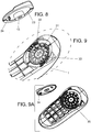
- Figures 8 and 9 respectively show an enlarged view of the lift plate of the initial embodiment and an enlarged view of the region of the bottom surface of the body that accommodates the lift plate.
- the center of that region has the lift plate mounting hole 31 that the screw goes into to secure the lift plate.
- the detent tab 24 of the lift plate can abut either an inner 33 or outer 32 region of waves of curved features of the body.
- the increased force needed to pivot the lift plate prevents inadvertent turning during use.
- Other detent structures include a ball 34 and socket 35 seen in FIG. 9A . They can be designed according to a trade-off in strength of retention of a set position and degree of difficulty in changing positions.
- both the left most and right most rear corners of the orthotic plate can have a small flat region that is at such an angle as to be parallel to the ground when the opposite side comes off the ground.
- the first embodiment described and illustrated above is an orthotic device worn in a shoe or other footwear.
- the tilt selector handle is used to pivot the lift plate to place a portion of its raised perimeter at a location that allows the raised portion to act as a forefoot post.
- FIGs. 10A - 10C The result of the operation is shown in FIGs. 10A - 10C .
- FIG. 10B the lift plate is in its neutral position and therefore no portion of it is touching the supporting surface or visible from this front view.
- FIG. 10A shows the lift plate pivoted as to create a forefoot post on the outside, tilting the forefoot to the inside by a specific angle 41.
- Figure 10C shows the opposite state.
- the lift plate is turned to place a raised area at the inner forefoot post area, tilting the foot to the outside.
- the supporting surface reference 44 and the respective tilt angles41 42 43 illustrate the phenomena.
- Figures 10D and 10E illustrate the neutral case of 10B in other views.
- a foot 64 is shown resting on this first orthotic embodiment set to the neutral position and resting on a supporting surface 65. Although the raised portion of the selector is close to the supporting surface, they are not touching.
- the orthotic is supported at its heel 66 and metatarsal positions 67.
- Figure 10E is a sectional view of the foot and orthotic in FIG. 10D along the line E-E.
- the possible tilting is not restricted to planes representing a pure inversion or eversion.
- the posting will support the foot in a more complex plane.
- the indicia can be used, possibly with accompanying instructions, to set the tilt to either deal with a valgus or a varus biomechanical issue of the wearer's condition.
- the range of tilt might be limited to 4 degrees.
- a unit for professional use might provide for a greater tilt, up to 8 degrees for example. This arrangement would prevent a consumer from a setting that might be extreme and unhealthful for them. With the professional unit, a podiatrist could treat a wider range of issues.
- the position of a post can determine the gait phase in which the post is "active".
- the shape and configuration of a pivot position of the lift plate can determine both an angle and the point in the gait cycle that the angle comes into play.
- embodiments could provide a good deal of the benefit otherwise only available with a podiatrist's custom orthotic.
- Systems can be deployed to help consumers make measurements and recommend versions of embodiments and settings.
- Another use of an adjustable forefoot posting system can be for individuals who partake in particular sports. A golfer might set her lift plates differently in the left and right feet in order to have the unique support that is optimal for each foot during a swing.
- some embodiments can feature interchangeable selectors. In versions where interchangeable selectors are provided for a user might switch selectors for differing activities or to accommodate different footwear. Skiing is one example that would benefit from this option.
- Adjustability can also be a benefit for young patients that might slowly grow out of a problem and can have the tilt readjusted over time. Some other patients might require such a large correction that it needs to be "dialed up" gradually.
- Figures 11A - 11C show a second embodiment.
- the lift plate 2' is a "slice of pie" of a circle.
- the perimeter has two symmetric beveled ramps 18R 18L.
- Figures 11B and 11C are both bottom views showing the slice of pie.
- Figure 11B shows the position of the lift plate 2' tilting the orthotic up at the right while FIG. 11C shows the position of the lift plate 2' tilting the orthotic up to the left.
- the third embodiment as seen in FIGs. 12A - 12C has two separate symmetric tilt selectors 50L 50R. One is on the left 50L and one on the right 50R. They are each slideable along their respective arcuate slots 51L 51R.
- the lift plates' can be thought of as portions of a lift plate as in the initial embodiment. Their repositionability by sliding moves them through the identical positions as that of the counterpart in the initial embodiment with the circular selector.
- a variation of this would be a circular lift plate rotationally constrained at its circumference by a slot structure rather than pivotally constrained at its center.
- Some versions, freed of needing a center connection, might consist primarily of an annular shaped circumferential configuration. This can have the benefit of reduced mass and structure.
- the fourth embodiment seen in FIGs. 13A - D has a lift or selector plate 56 similar to that of the second embodiment. However rather than only pivoting about a fixed center position, the selector is coupled to the orthotic plate by a slot 55. One extremity of the slot is the center position about which the selector can rotate in the same manner as that of the second embodiment. However, the slot allows the selector to be retracted towards the arch. This is an alternate configuration for moving a selector to a neutral position where no posting is presented. In some cases, this may allow a greater degree of flexing of the orthotic plate before a "bottoming out" of the tucked away selector occurs.
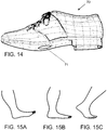
- a shoe 70 can have an opening 71 on its underside that allowed a user to make a pivoting adjustment to the lift plate. In that case, there would be no need to remove the orthotic plate from the item of footwear in order to make an adjustment.
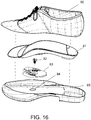
- FIG. 16 Another style of embodiment including footwear has a selector pivotally attached to the inside of a shoe or boot "upside down" rather than to the underside of a foot-receiving platform.
- the foot-receiving platform would rest on the floor of the shoe or boot including resting on a protrusion on the selector.
- FIG. 16 This embodiment is illustrated in FIG. 16 in a perspective, exploded manner.
- a shoe is shown cut into an upper portion 80 and a lower portion 85. This is not intended to imply any construction technique but to allow a view into the inside of the shoe.
- the lower portion has an opening 84 for attachment of the selector wheel 83.
- the wheel is rotationally coupled to the inner sole of the shoe by a screw 82.
- the orthotic plate itself 81 rests upon the inner sole and upon a portion of the wheel's protrusions if the wheel is turned appropriately to cause a tilt.
- Adjustability and variation on the forefoot angle would be comparable to other embodiments but with the selector not necessarily directly attached to the foot receiving plate. Adjustment could be by removal of the orthotic plate allowing access to the selector from the inside of the shoe. Alternatively, it could be adjusted externally as in the above shoe of FIG. 14 .
- the other shown embodiments have an analogous operation to that of the initial embodiment.
- the individual selectors would normally be positioned so that either the left or the right selector was fully retracted while the other was in a desired forward position.
- the fourth embodiment allows for a slidable retraction of the selector plate to an out-of-the-way position.
- the described devices might be composed of material including polypropylene, polyurethane, polyethylene, and polystyrene.
- Thermoplastic elastomeric materials and synthetic rubbers including thermoplastic rubbers are also useable in this application.
- Various degrees of hardness may be appropriate for the foot receiving shell platform and other for the lift plate.
- the posting system might be used on the exterior of a shoe or a shoe-sock as well.
- Footwear includes ice skates, roller skates, golf cleats, ski boots and other specialized foot coverings.
- a lock pin or other structure might be provided to keep the lift plate in a particular position.
- the body or foot receiving surface in some versions can be custom molded and in other versions pre-made in various sizes and styles.
- a kit might include multiple bodies and multiple lift plates. Generally, embodiments obviate the need for grinding or add-on posts.
- versions might have multiple lift plates or selectors that are independently pivotable or otherwise repositionable. Some versions might only provide tilt towards the outside and others might only provide tilt toward the inside. Others might provide a forward or a backward tilt.
Landscapes
- Health & Medical Sciences (AREA)
- General Health & Medical Sciences (AREA)
- Public Health (AREA)
- Epidemiology (AREA)
- Engineering & Computer Science (AREA)
- Heart & Thoracic Surgery (AREA)
- Orthopedic Medicine & Surgery (AREA)
- Biomedical Technology (AREA)
- Nursing (AREA)
- Vascular Medicine (AREA)
- Life Sciences & Earth Sciences (AREA)
- Animal Behavior & Ethology (AREA)
- Veterinary Medicine (AREA)
- Textile Engineering (AREA)
- Footwear And Its Accessory, Manufacturing Method And Apparatuses (AREA)
- Orthopedics, Nursing, And Contraception (AREA)
- Basic Packing Technique (AREA)
Claims (8)
- Fußstützvorrichtung zur Verwendung in Fußbekleidung, wobei die Fußstützvorrichtung umfasst:einen Orthesenkörper (12), der in seiner Hauptabmessung konvex ist und einen erhöhten Bogen in seinem zentralen Bereich vorsieht und eine halbsteife Fußaufnahmeplatte umfasst,eine Neigungsauswahleinrichtung (2), die an der Unterseite der Fußaufnahmeplatte anliegt und schwenkbar oder drehbar repositionierbar damit gekoppelt ist,wobei die Neigungsauswahleinrichtung (2) mindestens einen erhöhten umlaufenden Abschnitt mit Bereichen von mindestens zwei unterschiedlichen Höhen umfasst,wobei die Neigungsauswahleinrichtung (2) in alternativen Winkelpositionen repositionierbar ist, die effektiv alternative Neigungsgrade gegenüber der Ebene eines aufgenommenen Fußes vorsehen, wobei die Neigung mit Bezug auf eine Ebene erfolgt, auf der die Fußstützvorrichtung aufliegt, dadurch gekennzeichnet, dass die Neigungsauswahleinrichtung (2) aus einer neutralen Position repositionierbar ist, in der kein Abschnitt der Neigungsauswahleinrichtung (2) die Ebene berührt, auf der die Fußstützvorrichtung aufliegt.
- Fußstützvorrichtung nach Anspruch 1, wobei der Bereich des Schwenkens oder optional Drehens und die umlaufende Form derart beschaffen sind, dass ein variables Neigen im Allgemeinen nach außen vorgesehen ist.
- Fußstützvorrichtung nach Anspruch 1, wobei der Bereich des Schwenkens oder optional Drehens und die umlaufende Form derart beschaffen sind, dass ein variables Neigen im Allgemeinen nach innen vorgesehen ist.
- Fußstützvorrichtung nach Anspruch 1, wobei der Bereich des Drehens und die umlaufende Form derart sind, dass sowohl ein variables Neigen im Allgemeinen nach außen als auch in einer alternativen Winkelposition ein Neigen nach innen vorgesehen sind.
- Fußstützvorrichtung nach Anspruch 1, die in einen Fußbekleidungsartikel integriert ist.
- Fußstützvorrichtung nach Anspruch 5, wobei der Fußbekleidungsartikel ein Schuh ist.
- Fußstützvorrichtung nach Anspruch 1, wobei die Neigungsauswahlvorrichtung (2) durch Schwenken mit Bezug auf die Aufnahmeplatte beweglich ist, um verschiedene Vorderfußwinkel zu erzielen.
- Fußstützvorrichtung nach Anspruch 1, wobei die Neigungsauswahlvorrichtung (2) durch Drehen mit Bezug auf die Aufnahmeplatte beweglich ist, um verschiedene Vorderfußwinkel zu erzielen.
Applications Claiming Priority (3)
| Application Number | Priority Date | Filing Date | Title |
|---|---|---|---|
| US201061425196P | 2010-12-20 | 2010-12-20 | |
| US13/326,318 US8490301B2 (en) | 2010-12-20 | 2011-12-14 | Adjustable forefoot posting for orthotic |
| PCT/US2011/065078 WO2012087733A2 (en) | 2010-12-20 | 2011-12-15 | Adjustable forefoot posting for orthotic |
Publications (3)
| Publication Number | Publication Date |
|---|---|
| EP2654480A2 EP2654480A2 (de) | 2013-10-30 |
| EP2654480A4 EP2654480A4 (de) | 2014-06-25 |
| EP2654480B1 true EP2654480B1 (de) | 2021-03-17 |
Family
ID=46232516
Family Applications (1)
| Application Number | Title | Priority Date | Filing Date |
|---|---|---|---|
| EP11851414.0A Active EP2654480B1 (de) | 2010-12-20 | 2011-12-15 | Einstellbare vorderfuss-stütze für orthesen |
Country Status (8)
| Country | Link |
|---|---|
| US (1) | US8490301B2 (de) |
| EP (1) | EP2654480B1 (de) |
| CN (1) | CN103313619A (de) |
| AU (1) | AU2011349706B2 (de) |
| BR (1) | BR112013015150A2 (de) |
| CA (1) | CA2821424C (de) |
| ES (1) | ES2864076T3 (de) |
| WO (1) | WO2012087733A2 (de) |
Families Citing this family (12)
| Publication number | Priority date | Publication date | Assignee | Title |
|---|---|---|---|---|
| US9655400B2 (en) * | 2010-12-20 | 2017-05-23 | Allen Joseph Selner | Adjustable forefoot posting for orthotic |
| US8893397B2 (en) * | 2011-01-27 | 2014-11-25 | Eric G. Ward | Monopedal closed chain kinetic alignment device and method |
| US8756836B2 (en) * | 2011-02-23 | 2014-06-24 | Rylo, Inc. | Foot support |
| USD718026S1 (en) * | 2013-09-19 | 2014-11-25 | Premier Brands of America Inc. | Orthotic insole |
| USD729508S1 (en) | 2013-10-18 | 2015-05-19 | S.C. Johnson & Son, Inc. | Shoe insert |
| US10561512B2 (en) * | 2015-08-19 | 2020-02-18 | Orthomerica Products, Inc. | Adjustable walking sole for an orthosis |
| CN106073022B (zh) * | 2016-06-16 | 2018-07-06 | 上海交通大学 | 鞋底可穿戴式斜坡角度调节装置 |
| US20180140044A1 (en) * | 2016-11-21 | 2018-05-24 | Jason Guadalajara | System and Method for Stabilizing Footwear |
| CN106510087B (zh) * | 2016-12-19 | 2019-02-12 | 湘潭上瑞鞋业有限公司 | 一种矫正和治疗内翻足外翻的功能鞋 |
| CN107041802B (zh) * | 2017-04-19 | 2023-08-01 | 南京悦足健康科技有限公司 | 用于医用足部矫正辅具的底台装置及使用其的医用足部矫正辅具 |
| DE102018131852A1 (de) * | 2018-12-12 | 2020-06-18 | Ottobock Se & Co. Kgaa | Orthese und Verfahren zur Steuerung einer Orthese |
| US20250151849A1 (en) * | 2023-11-10 | 2025-05-15 | Stuart Steele | Shoe insert having a foot path director |
Family Cites Families (24)
| Publication number | Priority date | Publication date | Assignee | Title |
|---|---|---|---|---|
| US3377723A (en) * | 1966-07-18 | 1968-04-16 | Robert C. England | Adjustable golf shoe heel |
| GB1366270A (en) * | 1973-02-27 | 1974-09-11 | Glancy J J | Shoe heel |
| US5036604A (en) * | 1989-11-28 | 1991-08-06 | Rosen Henri E | Adjustable foot support system |
| US5345701A (en) * | 1991-04-26 | 1994-09-13 | Smith Leland R | Adjustable orthotic |
| US5241762A (en) * | 1992-03-31 | 1993-09-07 | Rosen Henri E | Adjustable fit shoe construction |
| US5685092A (en) | 1996-02-20 | 1997-11-11 | Prieskorn; David W. | Physiological motion enhancing shoe sole |
| US5768803A (en) | 1996-05-15 | 1998-06-23 | Levy; Dodd M. | Adjustable insole for support of painful foot areas |
| US7849612B2 (en) | 1997-09-15 | 2010-12-14 | Merel Epstein | Orthotic device |
| US6098319A (en) * | 1997-09-15 | 2000-08-08 | Epstein; Merel | Balancing appliance for footwear item |
| CA2245218C (en) | 1998-06-12 | 2006-02-07 | Merel Epstein | Orthotic device |
| IT1303332B1 (it) * | 1998-07-07 | 2000-11-06 | Bruno Silvestrini | Plantare pronosupinante per calzature. |
| JP2000125903A (ja) | 1998-10-22 | 2000-05-09 | Zenzo Nakagiri | ゴルフシューズの高さ調整スパイク |
| US6125557A (en) | 1998-10-26 | 2000-10-03 | Northwest Podiatric Lab | Orthotic assembly having stationary heel post and separate orthotic plate |
| US6609314B1 (en) | 2000-03-15 | 2003-08-26 | Benjamin B. Dubner | Mechanical interior shoe adjustment |
| US6393736B1 (en) | 2000-05-25 | 2002-05-28 | Greer Reed Biomedical, Llc | Adjustable brace orthotic and method of treating plantar fasciitis and related foot disorders |
| KR200265394Y1 (ko) | 2001-10-26 | 2002-02-21 | (주)포스텍 | 멀티경사조절신발 |
| US20030150137A1 (en) * | 2002-02-11 | 2003-08-14 | Rosen Henri E. | Orthopedically adjustable shoe construction |
| US6662475B2 (en) * | 2002-02-27 | 2003-12-16 | Columbia Insurance Company | Reversible heel |
| US20060059726A1 (en) * | 2004-09-22 | 2006-03-23 | Ching-Hui Song | Foot orthosis |
| US7681333B2 (en) | 2004-10-29 | 2010-03-23 | The Timberland Company | Shoe footbed system with interchangeable cartridges |
| WO2006050092A2 (en) | 2004-10-29 | 2006-05-11 | The Timberland Company | Shoe footbed with interchangeable cartridges |
| US7950168B2 (en) | 2007-05-22 | 2011-05-31 | Wolverine World Wide, Inc. | Adjustable footwear sole construction |
| KR100829144B1 (ko) | 2007-06-15 | 2008-05-13 | 황보석건 | 스노우보드 바인딩의 각도조절용 디스크 |
| GB0811550D0 (en) | 2008-06-24 | 2008-07-30 | Footworks Ltd | Footwear item |
-
2011
- 2011-12-14 US US13/326,318 patent/US8490301B2/en active Active
- 2011-12-15 AU AU2011349706A patent/AU2011349706B2/en active Active
- 2011-12-15 CN CN2011800605812A patent/CN103313619A/zh active Pending
- 2011-12-15 ES ES11851414T patent/ES2864076T3/es active Active
- 2011-12-15 WO PCT/US2011/065078 patent/WO2012087733A2/en not_active Ceased
- 2011-12-15 EP EP11851414.0A patent/EP2654480B1/de active Active
- 2011-12-15 BR BR112013015150A patent/BR112013015150A2/pt active IP Right Grant
- 2011-12-15 CA CA2821424A patent/CA2821424C/en active Active
Non-Patent Citations (1)
| Title |
|---|
| None * |
Also Published As
| Publication number | Publication date |
|---|---|
| US8490301B2 (en) | 2013-07-23 |
| EP2654480A2 (de) | 2013-10-30 |
| AU2011349706A1 (en) | 2013-07-04 |
| ES2864076T3 (es) | 2021-10-13 |
| CA2821424A1 (en) | 2012-06-28 |
| EP2654480A4 (de) | 2014-06-25 |
| WO2012087733A4 (en) | 2012-11-08 |
| BR112013015150A2 (pt) | 2016-02-16 |
| CA2821424C (en) | 2017-10-31 |
| AU2011349706B2 (en) | 2017-04-20 |
| CN103313619A (zh) | 2013-09-18 |
| US20120151803A1 (en) | 2012-06-21 |
| WO2012087733A3 (en) | 2012-09-13 |
| WO2012087733A2 (en) | 2012-06-28 |
Similar Documents
| Publication | Publication Date | Title |
|---|---|---|
| EP2654480B1 (de) | Einstellbare vorderfuss-stütze für orthesen | |
| US9655400B2 (en) | Adjustable forefoot posting for orthotic | |
| US6105283A (en) | Shoe insole for correction, control, and underfoot comfort | |
| US4869001A (en) | Foot and ankle orthotic for a skate boot or the like, and method | |
| US9770064B2 (en) | Support system for footwear providing support at or below the sustentaculum tali | |
| EP1209991B1 (de) | Therapieschuh oder -sandale | |
| US20040194344A1 (en) | User-customizable insoles for footwear and method of customizing insoles | |
| US20090133292A1 (en) | Footwear orthosis | |
| US6269554B1 (en) | Combined pronation and supination control plantar insert for shoes | |
| US9781971B2 (en) | Integrated medical shoe device | |
| US4783911A (en) | Skate boot assembly | |
| WO2015023717A1 (en) | Shoe with elastically flexible extension | |
| CN110545688A (zh) | 能量返回矫正系统 | |
| EP2204146B2 (de) | Fussorthese | |
| US20130340281A1 (en) | Flexible midfoot orthotic shoe insert | |
| US20130067764A1 (en) | Integrated medical shoe device | |
| US10667574B2 (en) | Functional orthotic support structure for footwear | |
| KR200370683Y1 (ko) | 운동용 고기능성 신발안창 | |
| KR100961520B1 (ko) | 신발용 발 교정구조 | |
| BR112013015150B1 (pt) | Dispositivo de apoio para o pé, e sistema de posicionamento de antepé | |
| CN100462021C (zh) | 鞋垫 | |
| CN118830686A (zh) | 一种具有改良鞋底和鞋舌结构的专业跳绳鞋 |
Legal Events
| Date | Code | Title | Description |
|---|---|---|---|
| PUAI | Public reference made under article 153(3) epc to a published international application that has entered the european phase |
Free format text: ORIGINAL CODE: 0009012 |
|
| 17P | Request for examination filed |
Effective date: 20130719 |
|
| AK | Designated contracting states |
Kind code of ref document: A2 Designated state(s): AL AT BE BG CH CY CZ DE DK EE ES FI FR GB GR HR HU IE IS IT LI LT LU LV MC MK MT NL NO PL PT RO RS SE SI SK SM TR |
|
| DAX | Request for extension of the european patent (deleted) | ||
| A4 | Supplementary search report drawn up and despatched |
Effective date: 20140523 |
|
| RIC1 | Information provided on ipc code assigned before grant |
Ipc: A43B 13/14 20060101ALI20140519BHEP Ipc: A43B 7/24 20060101ALI20140519BHEP Ipc: A43B 17/00 20060101ALI20140519BHEP Ipc: A43B 7/14 20060101AFI20140519BHEP Ipc: A61F 5/14 20060101ALI20140519BHEP |
|
| STAA | Information on the status of an ep patent application or granted ep patent |
Free format text: STATUS: EXAMINATION IS IN PROGRESS |
|
| 17Q | First examination report despatched |
Effective date: 20161110 |
|
| GRAP | Despatch of communication of intention to grant a patent |
Free format text: ORIGINAL CODE: EPIDOSNIGR1 |
|
| STAA | Information on the status of an ep patent application or granted ep patent |
Free format text: STATUS: GRANT OF PATENT IS INTENDED |
|
| INTG | Intention to grant announced |
Effective date: 20201007 |
|
| GRAS | Grant fee paid |
Free format text: ORIGINAL CODE: EPIDOSNIGR3 |
|
| GRAA | (expected) grant |
Free format text: ORIGINAL CODE: 0009210 |
|
| STAA | Information on the status of an ep patent application or granted ep patent |
Free format text: STATUS: THE PATENT HAS BEEN GRANTED |
|
| AK | Designated contracting states |
Kind code of ref document: B1 Designated state(s): AL AT BE BG CH CY CZ DE DK EE ES FI FR GB GR HR HU IE IS IT LI LT LU LV MC MK MT NL NO PL PT RO RS SE SI SK SM TR |
|
| REG | Reference to a national code |
Ref country code: GB Ref legal event code: FG4D |
|
| REG | Reference to a national code |
Ref country code: CH Ref legal event code: EP |
|
| REG | Reference to a national code |
Ref country code: DE Ref legal event code: R096 Ref document number: 602011070435 Country of ref document: DE |
|
| REG | Reference to a national code |
Ref country code: IE Ref legal event code: FG4D |
|
| REG | Reference to a national code |
Ref country code: AT Ref legal event code: REF Ref document number: 1371389 Country of ref document: AT Kind code of ref document: T Effective date: 20210415 |
|
| REG | Reference to a national code |
Ref country code: CH Ref legal event code: NV Representative=s name: NOVAGRAAF INTERNATIONAL SA, CH |
|
| REG | Reference to a national code |
Ref country code: LT Ref legal event code: MG9D |
|
| PG25 | Lapsed in a contracting state [announced via postgrant information from national office to epo] |
Ref country code: FI Free format text: LAPSE BECAUSE OF FAILURE TO SUBMIT A TRANSLATION OF THE DESCRIPTION OR TO PAY THE FEE WITHIN THE PRESCRIBED TIME-LIMIT Effective date: 20210317 Ref country code: HR Free format text: LAPSE BECAUSE OF FAILURE TO SUBMIT A TRANSLATION OF THE DESCRIPTION OR TO PAY THE FEE WITHIN THE PRESCRIBED TIME-LIMIT Effective date: 20210317 Ref country code: GR Free format text: LAPSE BECAUSE OF FAILURE TO SUBMIT A TRANSLATION OF THE DESCRIPTION OR TO PAY THE FEE WITHIN THE PRESCRIBED TIME-LIMIT Effective date: 20210618 Ref country code: BG Free format text: LAPSE BECAUSE OF FAILURE TO SUBMIT A TRANSLATION OF THE DESCRIPTION OR TO PAY THE FEE WITHIN THE PRESCRIBED TIME-LIMIT Effective date: 20210617 Ref country code: NO Free format text: LAPSE BECAUSE OF FAILURE TO SUBMIT A TRANSLATION OF THE DESCRIPTION OR TO PAY THE FEE WITHIN THE PRESCRIBED TIME-LIMIT Effective date: 20210617 |
|
| REG | Reference to a national code |
Ref country code: AT Ref legal event code: MK05 Ref document number: 1371389 Country of ref document: AT Kind code of ref document: T Effective date: 20210317 |
|
| REG | Reference to a national code |
Ref country code: NL Ref legal event code: MP Effective date: 20210317 |
|
| PG25 | Lapsed in a contracting state [announced via postgrant information from national office to epo] |
Ref country code: SE Free format text: LAPSE BECAUSE OF FAILURE TO SUBMIT A TRANSLATION OF THE DESCRIPTION OR TO PAY THE FEE WITHIN THE PRESCRIBED TIME-LIMIT Effective date: 20210317 Ref country code: RS Free format text: LAPSE BECAUSE OF FAILURE TO SUBMIT A TRANSLATION OF THE DESCRIPTION OR TO PAY THE FEE WITHIN THE PRESCRIBED TIME-LIMIT Effective date: 20210317 Ref country code: LV Free format text: LAPSE BECAUSE OF FAILURE TO SUBMIT A TRANSLATION OF THE DESCRIPTION OR TO PAY THE FEE WITHIN THE PRESCRIBED TIME-LIMIT Effective date: 20210317 |
|
| PG25 | Lapsed in a contracting state [announced via postgrant information from national office to epo] |
Ref country code: NL Free format text: LAPSE BECAUSE OF FAILURE TO SUBMIT A TRANSLATION OF THE DESCRIPTION OR TO PAY THE FEE WITHIN THE PRESCRIBED TIME-LIMIT Effective date: 20210317 |
|
| REG | Reference to a national code |
Ref country code: ES Ref legal event code: FG2A Ref document number: 2864076 Country of ref document: ES Kind code of ref document: T3 Effective date: 20211013 |
|
| PG25 | Lapsed in a contracting state [announced via postgrant information from national office to epo] |
Ref country code: LT Free format text: LAPSE BECAUSE OF FAILURE TO SUBMIT A TRANSLATION OF THE DESCRIPTION OR TO PAY THE FEE WITHIN THE PRESCRIBED TIME-LIMIT Effective date: 20210317 Ref country code: CZ Free format text: LAPSE BECAUSE OF FAILURE TO SUBMIT A TRANSLATION OF THE DESCRIPTION OR TO PAY THE FEE WITHIN THE PRESCRIBED TIME-LIMIT Effective date: 20210317 Ref country code: EE Free format text: LAPSE BECAUSE OF FAILURE TO SUBMIT A TRANSLATION OF THE DESCRIPTION OR TO PAY THE FEE WITHIN THE PRESCRIBED TIME-LIMIT Effective date: 20210317 Ref country code: AT Free format text: LAPSE BECAUSE OF FAILURE TO SUBMIT A TRANSLATION OF THE DESCRIPTION OR TO PAY THE FEE WITHIN THE PRESCRIBED TIME-LIMIT Effective date: 20210317 Ref country code: SM Free format text: LAPSE BECAUSE OF FAILURE TO SUBMIT A TRANSLATION OF THE DESCRIPTION OR TO PAY THE FEE WITHIN THE PRESCRIBED TIME-LIMIT Effective date: 20210317 |
|
| PG25 | Lapsed in a contracting state [announced via postgrant information from national office to epo] |
Ref country code: IS Free format text: LAPSE BECAUSE OF FAILURE TO SUBMIT A TRANSLATION OF THE DESCRIPTION OR TO PAY THE FEE WITHIN THE PRESCRIBED TIME-LIMIT Effective date: 20210717 Ref country code: RO Free format text: LAPSE BECAUSE OF FAILURE TO SUBMIT A TRANSLATION OF THE DESCRIPTION OR TO PAY THE FEE WITHIN THE PRESCRIBED TIME-LIMIT Effective date: 20210317 Ref country code: SK Free format text: LAPSE BECAUSE OF FAILURE TO SUBMIT A TRANSLATION OF THE DESCRIPTION OR TO PAY THE FEE WITHIN THE PRESCRIBED TIME-LIMIT Effective date: 20210317 Ref country code: PL Free format text: LAPSE BECAUSE OF FAILURE TO SUBMIT A TRANSLATION OF THE DESCRIPTION OR TO PAY THE FEE WITHIN THE PRESCRIBED TIME-LIMIT Effective date: 20210317 Ref country code: PT Free format text: LAPSE BECAUSE OF FAILURE TO SUBMIT A TRANSLATION OF THE DESCRIPTION OR TO PAY THE FEE WITHIN THE PRESCRIBED TIME-LIMIT Effective date: 20210719 |
|
| REG | Reference to a national code |
Ref country code: DE Ref legal event code: R097 Ref document number: 602011070435 Country of ref document: DE |
|
| PLBE | No opposition filed within time limit |
Free format text: ORIGINAL CODE: 0009261 |
|
| STAA | Information on the status of an ep patent application or granted ep patent |
Free format text: STATUS: NO OPPOSITION FILED WITHIN TIME LIMIT |
|
| PG25 | Lapsed in a contracting state [announced via postgrant information from national office to epo] |
Ref country code: DK Free format text: LAPSE BECAUSE OF FAILURE TO SUBMIT A TRANSLATION OF THE DESCRIPTION OR TO PAY THE FEE WITHIN THE PRESCRIBED TIME-LIMIT Effective date: 20210317 Ref country code: AL Free format text: LAPSE BECAUSE OF FAILURE TO SUBMIT A TRANSLATION OF THE DESCRIPTION OR TO PAY THE FEE WITHIN THE PRESCRIBED TIME-LIMIT Effective date: 20210317 |
|
| 26N | No opposition filed |
Effective date: 20211220 |
|
| PG25 | Lapsed in a contracting state [announced via postgrant information from national office to epo] |
Ref country code: SI Free format text: LAPSE BECAUSE OF FAILURE TO SUBMIT A TRANSLATION OF THE DESCRIPTION OR TO PAY THE FEE WITHIN THE PRESCRIBED TIME-LIMIT Effective date: 20210317 |
|
| PG25 | Lapsed in a contracting state [announced via postgrant information from national office to epo] |
Ref country code: IS Free format text: LAPSE BECAUSE OF FAILURE TO SUBMIT A TRANSLATION OF THE DESCRIPTION OR TO PAY THE FEE WITHIN THE PRESCRIBED TIME-LIMIT Effective date: 20210717 |
|
| PG25 | Lapsed in a contracting state [announced via postgrant information from national office to epo] |
Ref country code: MC Free format text: LAPSE BECAUSE OF FAILURE TO SUBMIT A TRANSLATION OF THE DESCRIPTION OR TO PAY THE FEE WITHIN THE PRESCRIBED TIME-LIMIT Effective date: 20210317 |
|
| REG | Reference to a national code |
Ref country code: BE Ref legal event code: MM Effective date: 20211231 |
|
| PG25 | Lapsed in a contracting state [announced via postgrant information from national office to epo] |
Ref country code: LU Free format text: LAPSE BECAUSE OF NON-PAYMENT OF DUE FEES Effective date: 20211215 Ref country code: IE Free format text: LAPSE BECAUSE OF NON-PAYMENT OF DUE FEES Effective date: 20211215 |
|
| PG25 | Lapsed in a contracting state [announced via postgrant information from national office to epo] |
Ref country code: BE Free format text: LAPSE BECAUSE OF NON-PAYMENT OF DUE FEES Effective date: 20211231 |
|
| PG25 | Lapsed in a contracting state [announced via postgrant information from national office to epo] |
Ref country code: HU Free format text: LAPSE BECAUSE OF FAILURE TO SUBMIT A TRANSLATION OF THE DESCRIPTION OR TO PAY THE FEE WITHIN THE PRESCRIBED TIME-LIMIT; INVALID AB INITIO Effective date: 20111215 Ref country code: CY Free format text: LAPSE BECAUSE OF FAILURE TO SUBMIT A TRANSLATION OF THE DESCRIPTION OR TO PAY THE FEE WITHIN THE PRESCRIBED TIME-LIMIT Effective date: 20210317 |
|
| P01 | Opt-out of the competence of the unified patent court (upc) registered |
Effective date: 20230523 |
|
| PG25 | Lapsed in a contracting state [announced via postgrant information from national office to epo] |
Ref country code: MK Free format text: LAPSE BECAUSE OF FAILURE TO SUBMIT A TRANSLATION OF THE DESCRIPTION OR TO PAY THE FEE WITHIN THE PRESCRIBED TIME-LIMIT Effective date: 20210317 |
|
| PG25 | Lapsed in a contracting state [announced via postgrant information from national office to epo] |
Ref country code: TR Free format text: LAPSE BECAUSE OF FAILURE TO SUBMIT A TRANSLATION OF THE DESCRIPTION OR TO PAY THE FEE WITHIN THE PRESCRIBED TIME-LIMIT Effective date: 20210317 |
|
| PG25 | Lapsed in a contracting state [announced via postgrant information from national office to epo] |
Ref country code: MT Free format text: LAPSE BECAUSE OF FAILURE TO SUBMIT A TRANSLATION OF THE DESCRIPTION OR TO PAY THE FEE WITHIN THE PRESCRIBED TIME-LIMIT Effective date: 20210317 |
|
| REG | Reference to a national code |
Ref country code: CH Ref legal event code: U11 Free format text: ST27 STATUS EVENT CODE: U-0-0-U10-U11 (AS PROVIDED BY THE NATIONAL OFFICE) Effective date: 20260101 |
|
| PGFP | Annual fee paid to national office [announced via postgrant information from national office to epo] |
Ref country code: DE Payment date: 20250930 Year of fee payment: 15 |
|
| PGFP | Annual fee paid to national office [announced via postgrant information from national office to epo] |
Ref country code: GB Payment date: 20251001 Year of fee payment: 15 |
|
| PGFP | Annual fee paid to national office [announced via postgrant information from national office to epo] |
Ref country code: IT Payment date: 20251121 Year of fee payment: 15 |
|
| PGFP | Annual fee paid to national office [announced via postgrant information from national office to epo] |
Ref country code: FR Payment date: 20251008 Year of fee payment: 15 |
|
| PGFP | Annual fee paid to national office [announced via postgrant information from national office to epo] |
Ref country code: ES Payment date: 20260114 Year of fee payment: 15 |
|
| PGFP | Annual fee paid to national office [announced via postgrant information from national office to epo] |
Ref country code: CH Payment date: 20260101 Year of fee payment: 15 |