EP2653777A1 - Dispositif d'éclairage et module d'éclairage indirect par corniches l'utilisant - Google Patents
Dispositif d'éclairage et module d'éclairage indirect par corniches l'utilisant Download PDFInfo
- Publication number
- EP2653777A1 EP2653777A1 EP20120176230 EP12176230A EP2653777A1 EP 2653777 A1 EP2653777 A1 EP 2653777A1 EP 20120176230 EP20120176230 EP 20120176230 EP 12176230 A EP12176230 A EP 12176230A EP 2653777 A1 EP2653777 A1 EP 2653777A1
- Authority
- EP
- European Patent Office
- Prior art keywords
- light
- guide plate
- light guide
- lighting device
- cove
- Prior art date
- Legal status (The legal status is an assumption and is not a legal conclusion. Google has not performed a legal analysis and makes no representation as to the accuracy of the status listed.)
- Withdrawn
Links
Images


Classifications
-
- G—PHYSICS
- G02—OPTICS
- G02B—OPTICAL ELEMENTS, SYSTEMS OR APPARATUS
- G02B6/00—Light guides; Structural details of arrangements comprising light guides and other optical elements, e.g. couplings
- G02B6/0001—Light guides; Structural details of arrangements comprising light guides and other optical elements, e.g. couplings specially adapted for lighting devices or systems
- G02B6/0011—Light guides; Structural details of arrangements comprising light guides and other optical elements, e.g. couplings specially adapted for lighting devices or systems the light guides being planar or of plate-like form
- G02B6/0033—Means for improving the coupling-out of light from the light guide
- G02B6/0035—Means for improving the coupling-out of light from the light guide provided on the surface of the light guide or in the bulk of it
-
- G—PHYSICS
- G02—OPTICS
- G02B—OPTICAL ELEMENTS, SYSTEMS OR APPARATUS
- G02B6/00—Light guides; Structural details of arrangements comprising light guides and other optical elements, e.g. couplings
- G02B6/0001—Light guides; Structural details of arrangements comprising light guides and other optical elements, e.g. couplings specially adapted for lighting devices or systems
- G02B6/0011—Light guides; Structural details of arrangements comprising light guides and other optical elements, e.g. couplings specially adapted for lighting devices or systems the light guides being planar or of plate-like form
- G02B6/0033—Means for improving the coupling-out of light from the light guide
- G02B6/005—Means for improving the coupling-out of light from the light guide provided by one optical element, or plurality thereof, placed on the light output side of the light guide
- G02B6/0055—Reflecting element, sheet or layer
Definitions
- the present invention relates to a lighting device and a cove lighting module using the lighting device, and more particularly, to a lighting device using light emitting diodes (LEDs) as light sources and a cove lighting module using the lighting device.
- LEDs light emitting diodes
- lamps are generally mounted on a ceiling to illuminate indoor space of the building.
- direct lighting is very harsh to a user's eyes, the user's eyes may get tired easily.
- indirect lighting is presented to provide illumination for the building.
- the indirect lighting is to use a cove lighting module to emit light onto a ceiling of the building, and then the light is reflected by the ceiling to provide illumination for the building.
- the indirect lighting may soften the light from the lighting device so as to overcome the disadvantage of the direct lighting, and meanwhile to make the indoor space with better atmosphere. Therefore, the indirect lighting has been increasingly applied in modern buildings.
- the cove lighting module used therein requires more light sources to provide sufficient light intensities to illuminate the indoor space of the building. In other words, the indirect lighting requires higher cost and more electricity power for providing sufficient light intensities.
- An aspect of the present invention is to provide a lighting device and a cove lighting module using the lighting device.
- the lighting device and the cove lighting module use light emitting diodes (LEDs) as light sources, thereby enabling the lighting device and the cove lighting module to provide sufficient light intensities with less power consumption.
- LEDs light emitting diodes
- the lighting device includes a shell body, at least one light emitting diode element, and at least one light guide plate.
- the light emitting diode element and the light guide plate are disposed in the shell body.
- the light guide plate is disposed adjacent to the light emitting diode element to enable light emitted by the light emitting diode element to enter the light guide plate through a light incident surface of the light guide plate and to exit from the light guide plate through a light emitting surface of the light guide plate, thereby forming an angle range with higher light intensities corresponding to a user-desirable light projected region.
- the lighting device includes a shell body, at least one light emitting diode element, at least one light guide plate, and at least one reflective plate.
- the light guide plate is disposed adjacent to the light emitting diode element to enable light emitted by the light emitting diode element to enter the light guide plate through a light incident surface of the light guide plate and to exit from the light guide plate through a light emitting surface of the light guide plate, thereby forming an angle range with higher light intensities corresponding to a user-desirable light projected region.
- the cove lighting module includes a light-receiving object and a lighting device.
- the light-receiving object has an opaque surface.
- the lighting device includes a shell body, at least one light emitting diode element, and at least one light guide plate.
- the light emitting diode element and the light guide plate are disposed in the shell body.
- the light guide plate is disposed adjacent to the light emitting diode element to enable light emitted by the light emitting diode element to enter the light guide plate through a light incident surface of the light guide plate, and to exit from the light guide plate through a light emitting surface of the light guide plate, thereby forming an angle range with higher light intensities corresponding to a user-desirable light projected region.
- the light leaving the light guide plate directly irradiates to the opaque surface of the light-receiving object.
- the lighting device and the cove lighting module of the present invention use LEDs as light sources, and the angle range with higher light intensities is corresponding to the region where a user desired to project the light, so that the lighting device and the cove lighting module may consume less power to provide sufficient light intensities. Further, in the embodiments of the present invention, the lighting device and the cove lighting module do not need to use additional optical films (such as a brightness enhancement film (BEF)), thus having lower cost.
- BEF brightness enhancement film
- Fig. 1 is a schematic diagram showing a structure of a cove lighting module 100 in accordance with an embodiment of the present invention.
- the cove lighting module 100 includes a lighting device 110, a light-receiving object 120, and a support member 130.
- the light-receiving object 120 has an opaque surface, or the material of the light-receiving object 120 is opaque material. In other words, the surface of the light-receiving object 120 is formed from fully reflective material or partially reflective material.
- the lighting device 110 is disposed on the support member 130, and project light onto the opaque surface of the light-receiving object 120, to provide illumination for indoor space of a building.
- the light-receiving object 120 is a ceiling of the building, and the lighting device 110 is mounted on a sidewall 140 of the building through the support member 130, but the embodiments of the present invention are not limited thereto.
- the lighting device 110 can be mounted on the ceiling of the building through the support member 130 to project light onto the ceiling of the building, as shown in Fig. 1 a.
- the lighting device 110 is mounted on the ceiling of the building through the support member 130 to project light onto the sidewall of the building, as shown in Fig. 1 b.
- Fig.2 is a schematic diagram showing a side structure of the lighting device 110 in accordance with the embodiment of the present invention.
- the lighting device 110 includes a shell body 112, a light emitting diode (LED) element 114 and a light guide plate 116.
- the shell body 112 has a light-source-receiving portion 112a and a light-emitting window 112b.
- the light-source-receiving portion 112a is used to receive the LED element 114, and the light-transmitting window 112b is used to provide a path for light emission.
- the light guide plate 116 is disposed adjacent to the LED element 114 to enable the light L emitted by the LED element 114 enter the light guide plate 116 through a light incident surface 116a of the light guide plate 116.
- the light L in the light guide plate 116 is guided by the structure of the light guide plate 116 to exit from the light guide plate 116 through a light emitting surface 116b of the light guide plate 116.
- the light L exiting from the light guide plate 116 emits out of the shell body 112 through the light-transmitting window 112b.
- a refractive index of the guide plate 116 is greater than 1, and the light guide plate 116 is formed from transparent material having a transmittance greater than 0.7, but the embodiments of the present invention are not limited thereto.
- Fig. 2a is a schematic diagram showing a side structure of the light guide plate 116 in accordance with the embodiment of the present invention.
- the light guide plate 116 of this embodiment has a reflective surface 116c.
- the reflective surface 116c is opposite to the light-emitting surface 116b.
- the reflective surface 116c has a plurality of microstructures S.
- the microstructures S are used to reflect the light L emitted to the reflective surface 116c to decrease the light L emitted out of the light guide plate 116 through the reflective surface 116c.
- the microstructure S is a convex structure having a size smaller than 500 um 2 , but the embodiments of the present invention are not limited thereto.
- the microstructure is a concave structure and the size thereof can be varied in accordance with demands of the user.
- the light guide plate 166 of this embodiment only the surface opposite to the light-emitting surface 116b of the light guide plate 116 has the microstructures S, but in other embodiments of the present invention, other surfaces of the light guide plate 116 may have the microstructures S.
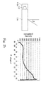
- Fig. 2b is a schematic diagram showing distribution of intensity of the light emitted by the lighting device 110 in accordance with the embodiment of the present invention.
- light from the lighting device 110 directly irradiates onto the light-receiving object.120.
- the light L directly irradiates onto the light-receiving object 120 without passing through any object (for example, a BEF).
- the emitting direction of the light emitted by the lighting device 110 is not orthogonal to the surface of the lighting device 100 (for example, the light-transmitting window 112b), and not symmetrical with respect to the surface of the lighting device 110.
- the light emitted by the lighting device 110 of this embodiment has highest intensity within an angle ⁇ at least 45 degrees, wherein the angle ⁇ represents an emitting angle of light with peak intensity emitted by each of smaller regions (or refer to pixels) of the light guide plate 116.
- the angle ⁇ is an angle between a main light emitting direction and a normal of the light emitting surface 116b.
- an angle range with highest light intensities (for example, the angle range is ⁇ ⁇ 45 ) is corresponding to a user-desirable light projected region, so that the illumination efficiency of the light emitted by the cove lighting module 100 is increased, accordingly.
- the lighting device 110 uses the combination the LEDs and the light guide plate as light sources, and the angle range with higher light intensities is corresponding to a user-desirable light projected region, so that the cove lighting module 100 can consume less power to provide sufficient illumination. Further, the lighting device 110 doest not use additional optical films, and thus the light L emitting from the LED element is directly projected onto the light-receiving object after exiting from the light guide plate 116 without passing through any optical film. Therefore, the cove lighting module 100 has lower cost.
- the lighting device of this embodiment may use other optical device to increase the illumination efficiency of the light L.
- the lighting device 110 may only include the shell body 112, the LED element 114, and the light guide plate 116, and no other optical devices are included.
- Fig. 3 is a schematic diagram showing a side structure of a lighting device 310 in accordance with the embodiment of the present invention.
- the lighting device 310 is similar to the lighting device 110, but the difference is in that the lighting device 310 further includes a reflective plate 318.
- the reflective plate 318 is disposed adjacent to the light guide plate 116, thereby reflecting the light L emitting from the LED element 114 back to the light guide plate 116.
- the reflective plate 318 is disposed under the light guide plate 116, and thus the light L emitting from the lower portion of the light guide plate 116 can be reflected back to the light guide plate 116, thereby increasing the illumination efficiency of the light L from the LED element 114.
- the reflection plate 318 is disposed under the light guide plate 116, but the embodiments of the present invention are not limited thereto. In other embodiments of the present invention, the reflective plate 318 can disposed on the side surface of the light guide plate 116, so that the illumination efficiency of the light L from the LED element 114 is increased.
- a reflective layer can be coated on an inner surface of the shell body 112 of the lighting device 310 to implement the function of the reflective plate 318.
- the lighting device 310 uses the reflective plate 318 to increase the illumination efficiency of the light L from the LED element 114 to further decrease the power consumption of the lighting device.
Applications Claiming Priority (1)
| Application Number | Priority Date | Filing Date | Title |
|---|---|---|---|
| TW101113492A TWI500884B (zh) | 2012-04-16 | 2012-04-16 | 照明裝置與應用此照明裝置之隱蔽式照明模組 |
Publications (1)
| Publication Number | Publication Date |
|---|---|
| EP2653777A1 true EP2653777A1 (fr) | 2013-10-23 |
Family
ID=46785222
Family Applications (1)
| Application Number | Title | Priority Date | Filing Date |
|---|---|---|---|
| EP20120176230 Withdrawn EP2653777A1 (fr) | 2012-04-16 | 2012-07-12 | Dispositif d'éclairage et module d'éclairage indirect par corniches l'utilisant |
Country Status (4)
| Country | Link |
|---|---|
| US (1) | US20130272025A1 (fr) |
| EP (1) | EP2653777A1 (fr) |
| JP (1) | JP5416808B2 (fr) |
| TW (1) | TWI500884B (fr) |
Cited By (1)
| Publication number | Priority date | Publication date | Assignee | Title |
|---|---|---|---|---|
| CN105444114A (zh) * | 2014-09-02 | 2016-03-30 | 展晶科技(深圳)有限公司 | 反射罩以及使用该反射罩的led照明装置 |
Families Citing this family (4)
| Publication number | Priority date | Publication date | Assignee | Title |
|---|---|---|---|---|
| JP7026332B2 (ja) * | 2017-08-10 | 2022-02-28 | パナソニックIpマネジメント株式会社 | 照明器具 |
| JP6986679B2 (ja) * | 2017-08-10 | 2021-12-22 | パナソニックIpマネジメント株式会社 | 照明器具、及び、照明器具セット |
| CN110160014B (zh) * | 2019-05-23 | 2024-04-26 | 欧普照明股份有限公司 | 一种照明灯具 |
| JP7398707B2 (ja) | 2020-02-27 | 2023-12-15 | パナソニックIpマネジメント株式会社 | 建材、施工方法、および照明装置 |
Citations (6)
| Publication number | Priority date | Publication date | Assignee | Title |
|---|---|---|---|---|
| WO2003026358A1 (fr) * | 2001-09-17 | 2003-03-27 | Color Kinetics Incorporated | Produits a diodes electroluminescentes |
| FR2872750A3 (fr) * | 2004-07-09 | 2006-01-13 | Hella Kgaa Hueck Co | Dispositif d'eclairage pour l'habitacle interieur d'un vehicule automobile |
| DE202008002873U1 (de) * | 2008-02-29 | 2008-05-15 | Martin, Andreas, Dipl.-Ing. | Lichtmodul für Raum- und Flächenausleuchtung |
| EP1983257A1 (fr) * | 2007-04-17 | 2008-10-22 | Philips Intellectual Property & Standards GmbH | Dispositif d'éclairage |
| US20100321952A1 (en) * | 2009-05-01 | 2010-12-23 | Zane Coleman | Light emitting devices and applications thereof |
| DE102011103319A1 (de) * | 2010-05-27 | 2011-12-01 | Webasto Ag | In ein Schiebedach oder ein Abdunklungssystem integrierte Umgebungsbeleuchtung |
Family Cites Families (6)
| Publication number | Priority date | Publication date | Assignee | Title |
|---|---|---|---|---|
| JP2004363062A (ja) * | 2003-06-09 | 2004-12-24 | Enplas Corp | 導光体、面光源装置及び画像表示装置 |
| JP4442322B2 (ja) * | 2004-02-04 | 2010-03-31 | パナソニック電工株式会社 | 足元灯 |
| WO2008126048A1 (fr) * | 2007-04-17 | 2008-10-23 | Philips Intellectual Property & Standards Gmbh | Dispositif d'éclairage |
| TWM325578U (en) * | 2007-07-20 | 2008-01-11 | Tennrich Int Corp | Light-emitting structure of a decoration plate and the electronic equipment it applied |
| US8092065B2 (en) * | 2009-07-31 | 2012-01-10 | Chung-Shan Institute of Science and Technology Armaments Bureau, Ministry of National Defense | Multi-function planar light source illumination lamp |
| JP5441622B2 (ja) * | 2009-11-04 | 2014-03-12 | 森ビル株式会社 | パネル型照明器具 |
-
2012
- 2012-04-16 TW TW101113492A patent/TWI500884B/zh active
- 2012-06-21 US US13/528,863 patent/US20130272025A1/en not_active Abandoned
- 2012-06-22 JP JP2012140733A patent/JP5416808B2/ja not_active Expired - Fee Related
- 2012-07-12 EP EP20120176230 patent/EP2653777A1/fr not_active Withdrawn
Patent Citations (6)
| Publication number | Priority date | Publication date | Assignee | Title |
|---|---|---|---|---|
| WO2003026358A1 (fr) * | 2001-09-17 | 2003-03-27 | Color Kinetics Incorporated | Produits a diodes electroluminescentes |
| FR2872750A3 (fr) * | 2004-07-09 | 2006-01-13 | Hella Kgaa Hueck Co | Dispositif d'eclairage pour l'habitacle interieur d'un vehicule automobile |
| EP1983257A1 (fr) * | 2007-04-17 | 2008-10-22 | Philips Intellectual Property & Standards GmbH | Dispositif d'éclairage |
| DE202008002873U1 (de) * | 2008-02-29 | 2008-05-15 | Martin, Andreas, Dipl.-Ing. | Lichtmodul für Raum- und Flächenausleuchtung |
| US20100321952A1 (en) * | 2009-05-01 | 2010-12-23 | Zane Coleman | Light emitting devices and applications thereof |
| DE102011103319A1 (de) * | 2010-05-27 | 2011-12-01 | Webasto Ag | In ein Schiebedach oder ein Abdunklungssystem integrierte Umgebungsbeleuchtung |
Cited By (2)
| Publication number | Priority date | Publication date | Assignee | Title |
|---|---|---|---|---|
| CN105444114A (zh) * | 2014-09-02 | 2016-03-30 | 展晶科技(深圳)有限公司 | 反射罩以及使用该反射罩的led照明装置 |
| CN105444114B (zh) * | 2014-09-02 | 2017-03-01 | 展晶科技(深圳)有限公司 | 反射罩以及使用该反射罩的led照明装置 |
Also Published As
| Publication number | Publication date |
|---|---|
| JP5416808B2 (ja) | 2014-02-12 |
| JP2013222704A (ja) | 2013-10-28 |
| TW201344107A (zh) | 2013-11-01 |
| TWI500884B (zh) | 2015-09-21 |
| US20130272025A1 (en) | 2013-10-17 |
Similar Documents
| Publication | Publication Date | Title |
|---|---|---|
| EP2478397B1 (fr) | Dispositif photoémetteur | |
| JPWO2013035788A1 (ja) | 照明装置および照明スタンド | |
| TWI537523B (zh) | 光學透鏡以及應用該光學透鏡的發光元件 | |
| EP2653777A1 (fr) | Dispositif d'éclairage et module d'éclairage indirect par corniches l'utilisant | |
| EP3497365B1 (fr) | Luminaire indirecte | |
| US20150124445A1 (en) | Light emitting diode light box | |
| TWI404893B (zh) | 無導光板之led發光構造 | |
| JP2009533815A5 (fr) | ||
| TWI413820B (zh) | 照明裝置與導光板 | |
| JP2012064558A (ja) | 光線を均一に発射させる導光柱及びこの導光柱を応用したledランプ | |
| TWI512230B (zh) | 發光二極體光源模組 | |
| US20170284611A1 (en) | Projection light source structure with bat-wing candle power distribution | |
| JP5119379B2 (ja) | 面照明光源装置及び面照明装置 | |
| JP2012114081A (ja) | グレア低減照明装置 | |
| KR101604667B1 (ko) | 직하 백라이트유닛 확산 렌즈 | |
| JP3211553U (ja) | 照明装置 | |
| JP2012243680A (ja) | 照明装置 | |
| US20130272024A1 (en) | Diffusion structure and lighting device with such diffusion structure | |
| KR20150108212A (ko) | 조명 부재 및 이를 이용하는 조명 장치 | |
| CN202647391U (zh) | 照明装置与应用此照明装置的隐蔽式照明模块 | |
| US20140218966A1 (en) | Lighting device and cove lighting module using the same | |
| KR20150108213A (ko) | 조명 장치 | |
| TWI559054B (zh) | Light emitting module | |
| US20130272026A1 (en) | Lateral light source processing module and lighting device with the same | |
| JP6345539B2 (ja) | 光束制御部材および発光装置 |
Legal Events
| Date | Code | Title | Description |
|---|---|---|---|
| PUAI | Public reference made under article 153(3) epc to a published international application that has entered the european phase |
Free format text: ORIGINAL CODE: 0009012 |
|
| 17P | Request for examination filed |
Effective date: 20120712 |
|
| AK | Designated contracting states |
Kind code of ref document: A1 Designated state(s): AL AT BE BG CH CY CZ DE DK EE ES FI FR GB GR HR HU IE IS IT LI LT LU LV MC MK MT NL NO PL PT RO RS SE SI SK SM TR |
|
| AX | Request for extension of the european patent |
Extension state: BA ME |
|
| 17Q | First examination report despatched |
Effective date: 20160229 |
|
| STAA | Information on the status of an ep patent application or granted ep patent |
Free format text: STATUS: THE APPLICATION IS DEEMED TO BE WITHDRAWN |
|
| 18D | Application deemed to be withdrawn |
Effective date: 20160712 |