EP2652796B1 - Method for bonding solar cells directly to polyimide - Google Patents
Method for bonding solar cells directly to polyimide Download PDFInfo
- Publication number
- EP2652796B1 EP2652796B1 EP11764921.0A EP11764921A EP2652796B1 EP 2652796 B1 EP2652796 B1 EP 2652796B1 EP 11764921 A EP11764921 A EP 11764921A EP 2652796 B1 EP2652796 B1 EP 2652796B1
- Authority
- EP
- European Patent Office
- Prior art keywords
- solar cell
- thermoplastic polyimide
- polyimide
- solar
- substrate
- Prior art date
- Legal status (The legal status is an assumption and is not a legal conclusion. Google has not performed a legal analysis and makes no representation as to the accuracy of the status listed.)
- Active
Links
Images


Classifications
-
- H—ELECTRICITY
- H10—SEMICONDUCTOR DEVICES; ELECTRIC SOLID-STATE DEVICES NOT OTHERWISE PROVIDED FOR
- H10F—INORGANIC SEMICONDUCTOR DEVICES SENSITIVE TO INFRARED RADIATION, LIGHT, ELECTROMAGNETIC RADIATION OF SHORTER WAVELENGTH OR CORPUSCULAR RADIATION
- H10F19/00—Integrated devices, or assemblies of multiple devices, comprising at least one photovoltaic cell covered by group H10F10/00, e.g. photovoltaic modules
- H10F19/80—Encapsulations or containers for integrated devices, or assemblies of multiple devices, having photovoltaic cells
- H10F19/804—Materials of encapsulations
-
- H—ELECTRICITY
- H10—SEMICONDUCTOR DEVICES; ELECTRIC SOLID-STATE DEVICES NOT OTHERWISE PROVIDED FOR
- H10F—INORGANIC SEMICONDUCTOR DEVICES SENSITIVE TO INFRARED RADIATION, LIGHT, ELECTROMAGNETIC RADIATION OF SHORTER WAVELENGTH OR CORPUSCULAR RADIATION
- H10F19/00—Integrated devices, or assemblies of multiple devices, comprising at least one photovoltaic cell covered by group H10F10/00, e.g. photovoltaic modules
- H10F19/80—Encapsulations or containers for integrated devices, or assemblies of multiple devices, having photovoltaic cells
- H10F19/807—Double-glass encapsulation, e.g. photovoltaic cells arranged between front and rear glass sheets
-
- H—ELECTRICITY
- H10—SEMICONDUCTOR DEVICES; ELECTRIC SOLID-STATE DEVICES NOT OTHERWISE PROVIDED FOR
- H10F—INORGANIC SEMICONDUCTOR DEVICES SENSITIVE TO INFRARED RADIATION, LIGHT, ELECTROMAGNETIC RADIATION OF SHORTER WAVELENGTH OR CORPUSCULAR RADIATION
- H10F19/00—Integrated devices, or assemblies of multiple devices, comprising at least one photovoltaic cell covered by group H10F10/00, e.g. photovoltaic modules
- H10F19/80—Encapsulations or containers for integrated devices, or assemblies of multiple devices, having photovoltaic cells
- H10F19/85—Protective back sheets
-
- H—ELECTRICITY
- H01—ELECTRIC ELEMENTS
- H01L—SEMICONDUCTOR DEVICES NOT COVERED BY CLASS H10
- H01L2224/00—Indexing scheme for arrangements for connecting or disconnecting semiconductor or solid-state bodies and methods related thereto as covered by H01L24/00
- H01L2224/80—Methods for connecting semiconductor or other solid state bodies using means for bonding being attached to, or being formed on, the surface to be connected
- H01L2224/80001—Methods for connecting semiconductor or other solid state bodies using means for bonding being attached to, or being formed on, the surface to be connected by connecting a bonding area directly to another bonding area, i.e. connectorless bonding, e.g. bumpless bonding
- H01L2224/808—Bonding techniques
- H01L2224/8085—Bonding techniques using a polymer adhesive, e.g. an adhesive based on silicone, epoxy, polyimide, polyester
-
- Y—GENERAL TAGGING OF NEW TECHNOLOGICAL DEVELOPMENTS; GENERAL TAGGING OF CROSS-SECTIONAL TECHNOLOGIES SPANNING OVER SEVERAL SECTIONS OF THE IPC; TECHNICAL SUBJECTS COVERED BY FORMER USPC CROSS-REFERENCE ART COLLECTIONS [XRACs] AND DIGESTS
- Y02—TECHNOLOGIES OR APPLICATIONS FOR MITIGATION OR ADAPTATION AGAINST CLIMATE CHANGE
- Y02E—REDUCTION OF GREENHOUSE GAS [GHG] EMISSIONS, RELATED TO ENERGY GENERATION, TRANSMISSION OR DISTRIBUTION
- Y02E10/00—Energy generation through renewable energy sources
- Y02E10/50—Photovoltaic [PV] energy
Definitions
- This application relates to solar cells and, more particularly, to methods of bonding a thermoplastic polyimide directly to a solar cell.
- JP 2008 047815 A discloses a unit module for a solar cell arrangement, wherein the unit module can be obtained from a wafer in which a polyimide film is laminated on at least one surface via a thermally fused layer made of a thermoplastic polyimide resin.
- the polyimide film comprises a tensile elastic modulus of not less than 4 GPa, and a linear expansion coefficient of not more than 12 ppm.
- US 4,542,257 A discloses an integral solar cell panel and a method for manufacturing an integral solar cell panel.
- the integral solar cell panel comprises a plurality of interconnected solar cells attached to a fiber-reinforced polyimide film substrate, wherein said solar cells are bonded to the surface of said polyimide film by the final curing of said polyimide.
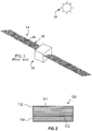
- a spacecraft 10 includes a number of rigid solar panels 12, which are shown in their deployed position.
- Solar arrays 14 which may include hundreds or thousands of solar cells 16 bonded to each solar panel 12 are used to provide electrical power to drive a variety of spacecraft systems and to recharge its batteries.
- the spacecraft rotates the solar panels 12 so that they receive direct illumination from the sun 18 to increase efficiency.
- the solar cells 16 include a flat photovoltaic wafer made from n-type or p-type crystalline semiconductor material, such as silicon, gallium-arsenide or germanium in or on which a thin surface layer of the opposite conductivity type is formed.
- n-type or p-type crystalline semiconductor material such as silicon, gallium-arsenide or germanium in or on which a thin surface layer of the opposite conductivity type is formed.
- the interface between the surface layer and the main region of the wafer defines a semiconductor junction. Illumination of the thin surface layer causes liberation of charge carriers, including electrons and holes in the region of the semiconductor junction, which migrate toward opposite surfaces to establish a potential across the solar cell.
- the solar panel 12 has three primary functions. First, the panel provides a rigid support structure with sufficient axial and bending stiffness for carrying the solar cell array 14 through a dynamically active launch environment into orbit and positioning it to receive illumination. Secondly, the front surface of the solar panel 12 to which the cells are bonded is electrically inert so that the individual solar cells 16 are electrically isolated. Lastly, the solar panel 12 serves as a heat sink to the space facing side (opposite sun 18) for the solar cell array.
- the spacecraft 10 of FIG. 1 is a rigid array as described. Thin film solar arrays are also possible that utilize a different stowed structure during launch that is lighter and more load efficient than the rigid panels, which might include a gossamer deployment structure that holds the solar cells out in space on the thin film solar array.
- the heat sink capabilities of the substrate must be sufficient to cool the solar cell array to maintain power efficiency.
- the solar panel should have low and/or matched thermal expansion properties compared to the solar cells.
- the temperature on the illuminated side of the array can be as high as +70°C and can be as low as -180°C or lower for thin film arrays on the back surface, which faces deep space. Due to these thermal expansion properties, warping or damage of the solar panel can occur.
- Solar cells are often supported by a graphite facesheet and an insulating layer facesheet that are bonded to the solar cell by a silicone-based adhesive called "RTV" adhesive.
- the cross-section of such solar cells typically include a solar cell CIC (coverglass, interconnects, cell), a layer of the RTV adhesive, an insulative layer facesheet (e.g., a DuPont TM Tedlar ® polyvinyl fluoride (PVF) film or a polyimide such as a Dupont TM Kapton ® polyimide film), and a graphite or Kevlar ® facesheet on a honeycomb substrate.
- the RTV is acknowledged in the industry as a source of degradation over the life of the solar arrays. Attempts to reduce the degradation of the solar arrays include the development of ultra low outgassing RTVs.
- RTVs have a coefficient of thermal expansion ("CTE") in the range of 100-200ppm/C.
- CTE coefficient of thermal expansion
- a Kapton ® polyimide film has a CTE around 17-20ppm/C and some solar cells have CTEs around 3-8ppm/C.
- the mismatch in the CTEs between the solar cell, RTV adhesive, and Kapton ® polyimide film is inherent in using this accepted adhesive as the standard adhesive for constructing solar arrays.
- One way to combat this mismatch has been to optimize the thickness of the RTV. But, increasing the thickness adds weight to the solar array, which depending upon the application intended for the solar array may be undesirable.
- a method includes constructing a solar cell panel by providing a solar cell that has a front side and a back side (the front side faces the sun during normal operation), heating a thermoplastic polyimide to at least its reflow temperature, flowing the thermoplastic polyimide onto the back side of the solar cell while heated to at least its reflow temperature, cooling the thermoplastic polyimide to a temperature below its reflow temperature to bond the thermoplastic polyimide directly to the solar cell, and bonding a substrate to the thermoplastic polyimide opposite the back side of the solar cell.
- the substrate comprises graphite, aramid-based material, carbon fibers, metal or metal alloys, and combinations thereof.
- the thermoplastic polyimide comprises: at least one diamine monomer and at least two dianhydride monomers, at least two diamine monomers and at least one dianhydride monomer, or at least two diamine monomers and two dianhydride monomers, wherein the diamine monomers are selected from 2,2-bis[4-(4aminophenoxy)phenyl]-hexafluoropropane and 4,4'-diaminobenzanilide and the dianhydride monomers are selected from 4,4'-(hexafluoroisopropylidene)di-phthalicanhydride and 3,3',4,4'-biphenyltetracarboxylic acid dianhydride.
- thermoplastic polyimide has a coefficient of thermal expansion of ⁇ 1%-5% of a coefficient of thermal expansion of the solar cell.
- the direct bonding of the thermoplastic polyimide to the solar cell is accomplished without an adhesive such as RTV adhesives.
- the methods may be used on thin film folded or flexible solar arrays, therefore the same benefits would be provided to rigid and flexible solar arrays.
- the elimination of the RTV adhesives reduces the overall weight of the solar arrays and reduces the disparity in CTE values for adjacent layers, which ultimately reduces the thermal stresses during thermal cycles of the solar arrays and provides for an increased life span of the arrays.
- the method further comprises providing a plurality of solar cells, electrically connecting each of the plurality of solar cells to at least one other solar cell forming an array.
- thermoplastic polyimide has a coefficient of thermal expansion that substantially matches a coefficient of thermal expansion of the solar cell.
- the coefficient of thermal expansion of the solar cell is about 3 to 8 ppm/°C.
- the reflow temperature is greater than about 300°C and less than about 400°C.
- the heating includes heating the thermoplastic polyimide to about 300°C to about 375°C.
- the cooling of the thermoplastic polyimide includes cooling to an ambient temperature.
- the method further comprises providing the thermoplastic polyimide as a polyimide sheet, and placing the polyimide sheet on the solar cell before heating, flowing, and cooling the thermoplastic polyimide.
- the substrate is bonded to the thermoplastic polyimide without an adhesive.
- Preferably bonding the substrate to the thermoplastic polyimide includes applying heat and pressure thereto after the cooling step.
- the method further comprises placing the substrate on the thermoplastic polyimide prior to cooling the thermoplastic polyimide.
- the substrate is a composite material
- the back side of the solar cell includes a metal or ceramic.
- the method further comprises electrically connecting a harness to the back side of the solar cell before flowing the thermoplastic polyimide, the harness being connectable to another solar cell, solar cell panel, or harness.
- a solar cell panel comprises: a solar cell having a front side and a back side, the front side of the solar cell facing the sun during normal operation; a thermoplastic polyimide bonded directly on the back side of the solar cell; and a substrate bonded to the thermoplastic polyimide opposite the back side of the solar cell.
- the substrate comprises graphite, aramid-based material, carbon fibers, metal or metal alloys, and combinations thereof.
- the thermoplastic polyimide comprises: at least one diamine monomer and at least two dianhydride monomers, at least two diamine monomers and at least one dianhydride monomer, or at least two diamine monomers and two dianhydride monomers, wherein the diamine monomers are selected from the group consisting of 2,2-bis[4-(4-aminophenoxy)phenyl]-hexafluoropropane and 4,4'-diaminobenzanilide, and combinations thereof, and wherein the dianhydride monomers are selected from the group consisting of 4,4'-(hexafluoroisopropylidene)di-phthalicanhydride and 3,3',4,4'-biphenyltetracarboxylic acid dianhydride, and combinations thereof.
- the thermoplastic polyimide has a coefficient of thermal expansion of ⁇ 1%-5% of a coefficient of thermal expansion of the solar cell..
- the modular cell array comprises the solar cell panel.
- the method includes bonding a substrate directly to the thermoplastic polyimide opposite the solar cell. This bonding step may occur subsequent to the flowing and cooling of the thermoplastic polyimide.
- the solar cell panel 100 includes a solar cell 112 having a front side 111 and a back side 113 with a thermoplastic polyimide 114 directly bonded to the back side 113 of the solar cell 112 (without an adhesive).
- the front side 111 of the solar cell 112 faces the sun and the thermoplastic polyimide 114 acts as an insulating layer within the solar cell panel 100.
- solar cell panel 100 does not include a substrate or facesheet beneath the polyimide. In this example, panel 100 is suitable for inclusion in a flexible array.
- panel 100 includes a substrate as shown in FIG. 3 and be suitable for inclusion in a rigid array.
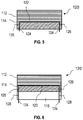
- a solar cell panel designated 100' and illustrated in cross-section, is shown that has a solar cell 112 with a thermoplastic polyimide 114 directly bonded to the back side 113 and that has a substrate 116 directly bonded to the thermoplastic polyimide 114 opposite the solar cell 112.
- the thermoplastic polyimide 114 has a first major surface 118 and a second major surface 120 with the first major surface 118 laminated to the solar cell 112 and the second major surface 120 laminated to the substrate 116.
- no adhesives are used between any of the layers of solar cell panel 100'. Instead, the thermoplastic polyimide 114 acts as an insulating layer and as an adherent to bond the components of the solar cell panel 100' together.
- the elimination of the adhesive may reduce the overall mass of a rigid solar array by about 6-10% and the mass of a flexible array by about 33-38%. Eliminating the RTV adhesives also improves the solar array by providing adjacent layers (the solar cell and the polyimide) that have CTEs that are more closely aligned (i.e., that have less disparity between them).
- a further benefit of bonding the solar cell 112 directly to the polyimide 114 is a more direct thermal path for the solar cell 112, which reduces the temperature of the solar cell 112 and inversely increases the efficiency thereof.
- the solar cell 112 of FIGS. 2 and 3 may be any type of solar cell.
- the solar cell 112 has a backside 113 that includes a metal or ceramic (i.e. silicon (Si), germanium (Ge), gallium arsenide (GaAs)).
- the metal or ceramic may cover the entire backside 113 of the solar cell 112 for more uniform bonding to the polyimide layer 114.
- the metal or ceramic may covers only part of the backside 113.
- the metal may include, but is not limited to, silver, gold, and/or zinc.
- Metal as used herein includes metals or metal alloys or compounds or composites including at least one metal or metal alloy.
- the type of solar cell 112 that the polyimide is directly bonded to is generally not limited. Suitable solar cells include advanced triple junction solar cells, single-junction or multi-junction or multicrystalline silicon solar cells, dual-junction solar cells, inverted metamorphic (IMM) solar cells, amorphous silicon solar cells, organic or inorganic solar cells, CIGS solar cells, single junction GaAs solar cell, and CdTe solar cells, and hereinafter developed solar cells.
- IMM inverted metamorphic
- the solar cells may have a CTE of about 3 to 8 ppm/°C depending on the temperature.
- the thermoplastic polyimide has a CTE that substantially matches the CTE of the solar cell.
- substantially matched CTEs provide a superior solar cell panel that has improved longevity because it will experience less fatigue during thermal cycling.
- the CTE of the polyimide is ⁇ about 1%-5% of the CTE value of the solar cell in the embodiments. For example, if the solar cell has a CTE of 8 ppm/°C, then the CTE of the polyimide is 8 ppm/°C ⁇ 0.08-0.4 ppm/C.
- the thermoplastic polyimide may have a CTE of about 3 to 8 ppm/°C.
- the solar cell has a CTE of about 3 ppm/°C and the thermoplastic polyimide has a CTE of about 3 ppm/°C.
- the solar cell has a CTE of about 4 ppm/°C and the thermoplastic polyimide has a CTE of about 4 ppm/°C.
- the solar cell has a CTE of about 5 ppm/°C and the thermoplastic polyimide has a CTE of about 5 ppm/°C.
- the solar cell has a CTE of about 6 ppm/°C and the thermoplastic polyimide has a CTE of about 6 ppm/°C. In another embodiment, the solar cell has a CTE of about 7 ppm/°C and the thermoplastic polyimide has a CTE of about 7 ppm/°C. In another embodiment, the solar cell has a CTE of about 8 ppm/°C and the thermoplastic polyimide has a CTE of about 8 ppm/°C.
- thermoplastic polyimides may also be characterized as being reflowable and have a reflow temperature of about 300°C or greater, but below a temperature that would liquefy or decompose the thermoplastic polyimide and/or a temperature that would damage the selected solar cell (typically greater than 400°C).
- the reflow temperature of the thermoplastic polyimide is at or between about 300°C to about 375°C.
- the reflow temperature of the thermoplastic polyimide is at or between about 315°C to about 350°C.
- a reflowable thermoplastic polyimide allows flexibility in the design of solar panels and solar arrays because the thermoplastic polyimide can be flowed to and/or over irregular shapes. It also enables fabrication of layers of uniform or non-uniform thickness.
- thermoplastic polyimides may also be characterized as being insulative. Suitable insulative thermoplastic polyimides for solar panel applications may have a dielectric strength of about or greater than 1000 V/mil. In one embodiment, the insulative thermoplastic polyimides may have a dielectric strength of about or greater than 1800 V/mil or 2000 V/mil.
- the thermoplastic polyimide may be present as a layer having a thickness of about 1 ⁇ 2 mil (0.0005 in) to about 10 mil (0.01 in). In one embodiment, the thickness of the thermoplastic polyimide layer may be about 1 mil (0.001 in) to about 2 mil (0.002 in).
- the thermoplastic polyimide may be a Novastrat ® polyimide available from ManTech SRS Technologies, Inc. of Huntsville, Alabama.
- the Novastrat ® polyimide product line provides polyimides with adjustable CTEs.
- the Novastrat ® polyimide may be adjusted to exhibit CTEs between -16 ppm/°C and 53 ppm/°C, including 0 ppm/°C, 10 ppm/°C, 17 ppm/°C, and 25 ppm/°C corresponding with CTE matches of graphite/epoxy, carbon steel, copper, and aluminum (respectively).
- the thermoplastic polyimides is a polyimide composition comprising a combination of diamine and dianhydride components that are specifically engineered to have a desired property, such as a CTE.
- the polyimide composition comprises at least one diamine monomer and at least two dianhydride monomer types, said polyimide composition engineered to have a desired property by varying the molar ratio of the at least two dianhydride components with respect to one another.
- the polyimide composition comprises at least two diamine monomer types and at least one dianhydride monomer, said polyimide composition engineered to have a desired property by varying the molar ratio of the at least two diamine components with respect to one another.
- the polyimide composition comprises at least two diamine monomer types and at least two dianhydride monomer types, said polyimide composition engineered to have a desired property by varying the molar ratio of the at least two dianhydride components with respect to one another, by varying the molar ratio of the at least two diamine components with respect to one another or by varying the molar ratio of the at least two dianhydride components with respect to one another and varying the molar ratio of the at least two diamine components with respect to one another.
- the diamine and dianhydride components may be any diamine or dianhydride components that are known in the art.
- the diamine monomers are 2,2-bis[4-(4aminophenoxy)phenyl]-hexafluoropropane (BDAF) or 4,4'-diaminobenzanilide (DABA) or combinations of the foregoing and the dianhydride monomers are 4,4'-(hexafluoroisopropylidene)di-phthalicanhydride (6-FDA) and 3,3',4,4'-biphenyltetracarboxylic acid dianhydride (s-BDPA) or combinations of the foregoing.
- BDAF 2,2-bis[4-(4aminophenoxy)phenyl]-hexafluoropropane
- DABA 4,4'-diaminobenzanilide
- dianhydride monomers are 4,4'-(hexafluoroisopropylidene)di-phthali
- increasing the mole percentage of BDAF in a polyimide composition comprising DABA (89 to 50 mole %) and s-BPDA as the dianhydride (100 mole %) increases the CTE value (determined at 25 to 200°C) of the polyimide composition from - 15.1 ppm/K (11 mole % BDAF) to 26.6 ppm/K (50 mole % BDAF).
- increasing the mole percentage of 6-FDA in a polyimide composition increases the CTE value (determined at 25 to 200°C) of the polyimide composition from -16.5 ppm/K (11 mole % 6-FDA) to 12.3 ppm/K (45 mole % 6-FDA).
- increasing the mole percentage of 6-FDA in a polyimide composition comprising DABA (67 mole %), BDAF (33 mole %) and s-BPDA (11 to 33 mole %) increases the CTE value (determined at 25 to 200°C) of the polyimide composition from 15.6 ppm/K (11 mole % 6-FDA) to 31.8 ppm/K (33 mole % 6-FDA).
- increasing the mole percentage of BDAF in a polyimide composition comprising DABA (100 and 67 mole %), s-BPDA (89 mole %) and 6-FDA (89 mole %) increases the CTE value (determined at 25 to 200°C) of the polyimide composition from -16.5 ppm/K (0 mole % BDAF) to 15.6 ppm/K (33 mole % 6-FDA).
- the polyimide compositions may be prepared as is generally known in the art (for example, see U.S. Pat. Nos. 3,179,630 and 3,179,634 , " Polyimides-Thermally Stable Polymers", Plenum Publishing (1987 ), " Synthesis and Characterization of Thermosetting polyimide Oligomers for Microelectronics Packaging, Dunson D. L., (Dissertation submitted to faculty of the Virginia Polytechnic Institute and State University, Apr. 21, 2000 ) and as described in as described in U.S. Published Patent Application No. 2008/0214777 to Poe (assigned to SRS Technologies ).
- the thermoplastic polyimides may be a bulk source that is heated to its reflow temperature and poured over the solar cells to form a polyimide layer.
- the thermoplastic polyimides may be a polyimide sheet that may be laid onto the solar cells and heated to a reflow temperature such that the polyimides flows onto and/or over the solar cells.
- the "sheet” may come in many different forms, for example but not limited thereto, a mesh or scrim, strips, or a film having a uniform or non-uniform major surface.
- the thermoplastic polyimide sheet may be "B-stage" cured such that the polyimide is handleable as a sheet, but is still reflowable once heated to the reflow temperature of the particular polyimide.
- Substrate 116 may be any suitable material and hereinafter developed material for aerospace, aeronautical, and/or terrestrial applications. Depending upon the application, the properties of the substrate may vary. In aerospace applications, for example, a suitable substrate may be a one that provides high stiffness and is light weight. When the substrate 116 is present and provides stiffness, a rigid solar array may be formed using a plurality of solar cell panels, such as solar cell panel 110'. In aeronautical applications, a suitable substrate may be any material suitable for the skin of an aircraft or other aeronautical apparatus or device. In terrestrial applications, a suitable substrate may be one that draws heat away from the solar cells. The substrate may also provides a solid surface for mounting the solar cell-polyimide composite thereto and/or into a solar array.
- the substrate 116 is or includes graphite, aramid-based materials, carbon fiber materials, metal or metal alloys, and/or composites containing one or more of these materials.
- the substrate may be or include graphite and/or aramid-based materials.
- the substrate may be or include graphite, aramid-based, carbon fiber and/or aluminum metal or metal alloy materials.
- the substrate may be or include a composite material, for example, a carbon fiber/epoxy composite or a ceramic composite.
- the substrate may be or include copper and/or aluminum metals or metal alloys.
- a solar panel 110' includes the polyimide 114 bonded to a substrate 116, which may be a honeycomb composite substrate.
- the honeycomb composite substrate 116 may include a facesheet 132 and a honeycomb core 130 that are co-cured, laminated, or directly bonded to the polyimide layer 114.
- a graphite or an aramid-based material is the facesheet 132 of the honeycomb composite substrate 116.
- the honeycomb core 130 functions as a heat sink and stiffener structure.
- honeycomb refers to any non-solid pattern.
- the preferred pattern has hexagonal, i.e. "honeycomb", shaped cells. Alternately, the pattern could be squares or some other geometric shape.
- the core is preferably formed from a light weight, high thermally conductive material such as aluminum.
- the solar cells 112 may be interconnected to at least one other solar cell by traditional interconnections.
- the solar cell panels, generally designated 120 and 120' in FIGS. 5-6 may include at least one embedded harness 122, 123, respectively, for interconnecting the solar cells and/or solar cell panels to one another.
- Solar cell panel 120 FIG. 5
- the harness 122 is embedded in the polyimide layer 114 such that the harness is in electrical contact with the solar cell 112.
- the harness 122 may include first leads 124 that extend through the polyimide layer 114 and exit a major surface of the polyimide 114 or the panel 120 opposite the solar cell 112.
- second leads 126 may be present that extend out of an edge (left or right side relative to the illustration on the page) of the polyimide layer 114.
- the harness 122 may include both the first and second leads 124, 126. While two leads have been illustrated for each of the first leads 124 and the second leads 126, the harness is not limited thereto.
- any number of leads may be appropriate for connecting a plurality of solar cells 112 and/or solar panels 120 together.
- the harness 122 of FIG. 5 may have any shape or configuration that allows for embedding the harnesses in the thermoplastic polyimide 114 or for flowing the thermoplastic polyimide around the harness 122 and over the solar cell 112.
- the harness 122 may be in the form of a mesh or scrim that has leads such as leads 124, 126 extending therefrom.
- the harness 122 may be a flat flexible copper or aluminum harness or other thin wire harness materials/alloys.
- the material for the harness is preferably selected to be substantially CTE matched to the CTE values of the solar cell and/or the thermoplastic polyimide.
- solar cell panel 120' is similar to solar cell panel 100' of FIG. 3 having substrate 116, but including harness 123. Similar to harness 122 of FIG.5 , harness 123 in FIG. 6 is embedded in the polyimide layer 114 such that the harness 123 is in electrical contact with the solar cell 112.
- the harness 123 may include first leads 124 that exit a major surface of the substrate 116 opposite the solar cell 112, second leads 126 that extend out of an edge (left or right side relative to the illustration on the page) of polyimide layer 114, and/or third leads 128 exiting or extending out of an edge of the substrate 116.
- leads 124, 126, and 128 are not limited and may be anywhere along the edge of polyimide 114 for leads 126, 128 and anywhere along the major surface of the substrate 116 for leads 124. While two leads have been illustrated for each of first leads 124, second leads 126, and third leads of harness 123, the harness is not limited thereto. One of skill in the art will appreciate that any number of leads may be appropriate for connecting a plurality of solar cells 112 and/or solar cell panel 120' together.
- harness 123 may have any shape or configuration that allows for embedding the harnesses in the thermoplastic polyimide 114 or for flowing the thermoplastic polyimide around the harness 123 and over the solar cell 112.
- the harness 123 may be in the form of a mesh or scrim that has leads such as leads 124, 126 extending therefrom.
- the harness 123 may be a flat flexible copper or aluminum harness or other thin wire harness materials/alloys.
- the solar cell panels may be formed in modular units having from one solar cell to about 20 solar cells bonded together by the thermoplastic polyimide.
- the modular unit includes one to eight solar cells. Accordingly, the modular unit may include eight solar cells, seven solar cells, six solar cells, five solar cells, four solar cells, three solar cells, two solar cells, or one solar cell. In an array having hundreds of solar cells, when one modular unit is damaged or defective it may be replaced.
- the harnesses described above can provide connectability for the modular units that also contributes to the replaceability thereof.
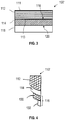
- step 202 providing a solar cell that has a front side and a back side where the front side faces the sun during normal operation; step 204 - heating a thermoplastic polyimide to at least its reflow temperature; step 206 - flowing the thermoplastic polyimide onto the back side of the solar cell; step 208 - cooling the thermoplastic polyimide to a temperature below its reflow temperature to bond the thermoplastic polyimide directly to the solar cell.
- the solar cell provided may be any type of solar cell, as described above.
- Step 204 may include heating the thermoplastic polyimide to a reflow temperature of greater than about 300°C, but below a temperature that would liquefy or decompose the thermoplastic polyimide and/or a temperature that would damage the selected solar cell.
- the temperatures may vary depending upon the melting, or reflow, temperature of the thermoplastic being used.
- appropriate thermoplastics may have melting points ranging from about 100°C to about 400°C, and the temperature for the heating step may vary from about 100°C to about 400°C.
- the reflow temperature of the thermoplastic polyimide is at or between about 300°C to about 375°C. Accordingly, step 204 includes heating to a temperature at or between about 300°C to about 375°C.
- the reflow temperature of the thermoplastic polyimide is at or between about 315°C to about 350°C.
- the thermoplastic should have a reflow temperature above temperatures at which the solar cell panel may be subsequently processed and/or used. In this manner, the thermoplastic may not reflow subsequent to attachment.
- the heating step 204 may be performed in or by any suitable apparatus or mechanisms for controlling the heat applied to the thermoplastic polyimide.
- the heating step may be performed by an oven, microwave or other forms of radiation, a hot water bath, or other apparatus or methods.
- the application of pressure is generally not necessary for the steps of method 200 and as such the steps may be performed at ambient pressure. If changing or controlling the pressure is desired, it may be applied by any suitable means.
- the step 206 of flowing the thermoplastic polyimide may be by any known or herein after developed mechanism or method.
- a solar cell, plurality of solar cells, and/or sheet of solar cells may be placed on a casting table (optionally treated with a release agent) with the back side of the solar cells facing up and the thermoplastic polyimide after being heated to a reflow temperature may be poured or flowed over the solar cells.
- the thermoplastic polyimide is then cooled to ambient temperature. Thereafter, the solar panel(s) may be removed from the casting table.
- the solar cell, plurality of solar cells, and/or sheet of solar cells may be suspended or transported for continuous or discontinuous application of the flowable thermoplastic polyimide using known or herein after developed coating techniques. After coating the solar cell(s) with the flowable thermoplastic polyimide, the polyimide is allowed to cool to ambient temperature.
- a solar cell panel having a cross section similar to that depicted in FIG. 2 is formed. These solar cell panels may be included in a flexible array of solar panels.
- the method 200 includes the step 210 of bonding a substrate to thermoplastic polyimide opposite the back side of the solar cell.
- Step 210 may be performed subsequent to the bonding of the thermoplastic polyimide to the solar cell (steps 204 through 206) or contemporaneously therewith. If bonded subsequently, step 210 may include the application of heat and pressure to bond the substrate to the thermoplastic polyimide. It is understood that the bonding step 210 may be performed in or by any suitable apparatus or mechanisms, including but not limited to an autoclave or other similar apparatus for controlling the heat and pressure applied to the solar cell and polyimide. In one embodiment, the heating step may be performed by an oven, a hot water bath, microwaves or other forms of radiation, or other apparatus or methods. If the substrate is bonded contemporaneously with the solar cell, the substrate may be placed on the thermoplastic polyimide prior to the cooling step 208, preferably after the flowing step 206.
- the solar cell provided in step 202 may include a harness electrically connected to the solar cell, typically to the back side of the solar cell.
- the method may include a step of electrically connecting the harness to the solar cell.
- the harness is preferably electrically connected to the solar cell before flowing the thermoplastic polyimide thereover.
- the harness is characterized as being connectable to another solar cell, solar cell panel, or harness.
- thermoplastic polyimides Suitable solar cells, thermoplastic polyimides, substrates, and harnesses for use in the method 200 are discussed above with respect to FIGS. 2-6 .
- step 302 providing a plurality of solar cells that each have a front side and a back side where the front side faces the sun during normal operation; step 304 - heating a thermoplastic polyimide to at least its reflow temperature; step 306 - flowing the thermoplastic polyimide onto the back sides of the plurality of solar cells; step 308 - cooling the thermoplastic polyimide to a temperature below its reflow temperature to bond the thermoplastic polyimide directly to the plurality of solar cells; and step 309 - electrically connecting the plurality of solar cells to at least one other solar cell within the array.
- each solar cell 112 may include a harness 120 or 120' electrically connected thereto.
- the harness 120, 120' is electrically connected to the back side of the solar cell 112.
- the method 300 may include a step of electrically connecting a harness to each of the solar cells.
- the harness 120, 120' is preferably electrically connected to the solar cell 112 before flowing the thermoplastic polyimide 114 thereover.
- the harness is characterized as being connectable to another solar cell, solar cell panel, or harness.
- the harness 120, 120' may be an extension harness that connects a solar cell panel 100 or 100' to at least one other solar cell panel 100 or 100'.
- a separate connection may be provided for solar cell 112 to solar cell 112 interconnection.
- the harness 120, 120' may carry power back to the platform upon which the panels are mounted such as a spacecraft, aircraft, or terrestrial structure.
- the harness 120, 120' may provide both the solar cell 112 to solar cell 112 interconnection and the interconnection that interconnects a plurality of solar cell panels to carry power back to the platform upon which the panels are mounted.
- the heating step 304, the flowing step 306, and the cooling step 308 may be similar to steps 204 through 208 described above for method 200.
- method 300 also includes step 309 where the plurality of solar cells are each electrically connected to at least one other solar cell within the array.
- Step 309 may include any method of electrically connecting the leads of the harness, described above with respect to FIGS. 5 and 6 , to a harness of another solar cell panel or directly to another solar cell or solar cell panel.
- step 309 may include soldering the leads together or to another solar cell or solar cell panel.
- step 309 may include twisting the leads of two or more solar cell panels together using a wire cap.
- step 309 may include plugging a lead from a harness of a first solar cell panel into a receptacle on another harness or a second solar cell panel.
- Method 300 also includes a step, step 310, similar to step 210 of FIG. 7 , of bonding a substrate to a face of the multilayer polyimide such as the face opposite the solar cell.
- step 310 similar to step 210 of FIG. 7 , of bonding a substrate to a face of the multilayer polyimide such as the face opposite the solar cell.
- the bonding of the substrate may occur subsequent to the bonding of the solar cell to the thermoplastic polyimide or contemporaneously therewith.
- the application of pressure is generally not necessary for the steps of method 300 and as such the steps may be performed at ambient pressure. If changing or controlling the pressure is desired, it may be applied by any suitable means.
- the substrate includes a composite matrix and pressure may be applied during the flowing step 306 to ensure that the thermoplastic polyimide flows into any voids present on/in the composite matrix.
- thermoplastic polyimides Suitable solar cells, thermoplastic polyimides, substrates, and harnesses for use in the method 300 are discussed above with respect to FIGS. 2-6 .
Landscapes
- Photovoltaic Devices (AREA)
Applications Claiming Priority (2)
| Application Number | Priority Date | Filing Date | Title |
|---|---|---|---|
| US12/970,230 US8232129B2 (en) | 2010-12-16 | 2010-12-16 | Bonding solar cells directly to polyimide |
| PCT/US2011/052788 WO2012091771A1 (en) | 2010-12-16 | 2011-09-22 | Method for bonding solar cells directly to polyimide |
Publications (2)
| Publication Number | Publication Date |
|---|---|
| EP2652796A1 EP2652796A1 (en) | 2013-10-23 |
| EP2652796B1 true EP2652796B1 (en) | 2022-01-05 |
Family
ID=44759785
Family Applications (1)
| Application Number | Title | Priority Date | Filing Date |
|---|---|---|---|
| EP11764921.0A Active EP2652796B1 (en) | 2010-12-16 | 2011-09-22 | Method for bonding solar cells directly to polyimide |
Country Status (7)
| Country | Link |
|---|---|
| US (1) | US8232129B2 (enExample) |
| EP (1) | EP2652796B1 (enExample) |
| JP (1) | JP5887357B2 (enExample) |
| KR (1) | KR101660570B1 (enExample) |
| CN (1) | CN103262258B (enExample) |
| CA (1) | CA2814755C (enExample) |
| WO (1) | WO2012091771A1 (enExample) |
Families Citing this family (10)
| Publication number | Priority date | Publication date | Assignee | Title |
|---|---|---|---|---|
| NL2012560B1 (en) * | 2014-04-03 | 2016-03-08 | Stichting Energieonderzoek Centrum Nederland | Solar panel and method for manufacturing such a solar panel. |
| US10059471B2 (en) | 2014-10-24 | 2018-08-28 | Solaero Technologies Corp. | Method for releasing a deployable boom |
| US9004410B1 (en) * | 2014-10-24 | 2015-04-14 | Alliance Spacesystems, Llc | Deployable boom for collecting electromagnetic energy |
| FR3028515B1 (fr) * | 2014-11-14 | 2018-01-12 | Thales | Structure composite comportant une resine chargee avec des feuillets plans de graphene a conductivite thermique et conductivite electrique renforcees, notamment pour satellite |
| WO2016205722A1 (en) * | 2015-06-17 | 2016-12-22 | Stc.Unm | Metal matrix composites for contacts on solar cells |
| US12074228B2 (en) | 2015-06-17 | 2024-08-27 | Unm Rainforest Innovations | Metal-carbon-nanotube metal matrix composites for metal contacts on photovoltaic cells |
| US10276742B2 (en) * | 2015-07-09 | 2019-04-30 | Solaero Technologies Corp. | Assembly and mounting of solar cells on space vehicles or satellites |
| JP7030683B2 (ja) | 2015-07-27 | 2022-03-07 | シエラ・スペース・コーポレイション | 宇宙空間品質の太陽電池アレイの製造方法 |
| CN106409958B (zh) * | 2016-09-21 | 2017-08-11 | 云南临沧鑫圆锗业股份有限公司 | 基于石墨衬底的倒装三结太阳电池及其制备方法 |
| US20220037541A1 (en) * | 2020-07-30 | 2022-02-03 | Northrop Grumman Systems Corporation | Flexible solar array for extraterrestrial deployment |
Family Cites Families (20)
| Publication number | Priority date | Publication date | Assignee | Title |
|---|---|---|---|---|
| US3179634A (en) | 1962-01-26 | 1965-04-20 | Du Pont | Aromatic polyimides and the process for preparing them |
| US3179630A (en) | 1962-01-26 | 1965-04-20 | Du Pont | Process for preparing polyimides by treating polyamide-acids with lower fatty monocarboxylic acid anhydrides |
| US4394529A (en) * | 1981-08-05 | 1983-07-19 | Rca Corporation | Solar cell array with lightweight support structure |
| US4542257A (en) | 1984-04-27 | 1985-09-17 | Hughes Aircraft Company | Solar cell array panel and method of manufacture |
| JPH02181975A (ja) * | 1989-01-07 | 1990-07-16 | Nitto Denko Corp | フィルム太陽電池 |
| US5614033A (en) | 1995-08-08 | 1997-03-25 | Hughes Aircraft Company | Rigid solar panel with discrete lattice and carrier structures bonded together |
| JPH11100517A (ja) * | 1997-09-29 | 1999-04-13 | Hitachi Chem Co Ltd | 樹脂ペースト、膜形成法、電子部品及び半導体装置 |
| US6313396B1 (en) | 2000-05-22 | 2001-11-06 | The Boeing Company | Lightweight solar module and method of fabrication |
| US6410362B1 (en) | 2000-08-28 | 2002-06-25 | The Aerospace Corporation | Flexible thin film solar cell |
| US6300158B1 (en) | 2000-08-28 | 2001-10-09 | Iowa Thin Films | Integrated solar power module |
| EP1910078A4 (en) * | 2005-08-02 | 2012-06-06 | Nexolve Corp | HETEROPOLYMERIC COMPOSITIONS OF POLYIMIDE POLYMER |
| WO2007088892A1 (ja) * | 2006-02-02 | 2007-08-09 | Mitsui Chemicals, Inc. | 太陽電池モジュール用裏面保護基板、並びに、太陽電池モジュール及び発電装置 |
| JP2008047815A (ja) * | 2006-08-21 | 2008-02-28 | Toyobo Co Ltd | 光電変換装置 |
| JP2008047813A (ja) * | 2006-08-21 | 2008-02-28 | Toyobo Co Ltd | 光電変換装置 |
| US20090188603A1 (en) * | 2008-01-25 | 2009-07-30 | Applied Materials, Inc. | Method and apparatus for controlling laminator temperature on a solar cell |
| JP5481929B2 (ja) * | 2008-05-20 | 2014-04-23 | 宇部興産株式会社 | ポリイミド金属積層体および太陽電池 |
| US20090288699A1 (en) * | 2008-05-20 | 2009-11-26 | E.I. Du Pont De Nemours And Company | Laminate structures for high temperature photovoltaic applications, and methods relating thereto |
| JP2009290164A (ja) | 2008-06-02 | 2009-12-10 | Toyobo Co Ltd | 光電変換装置 |
| US20100330731A1 (en) * | 2009-06-27 | 2010-12-30 | Twin Creeks Technologies, Inc. | Method to form a thin semiconductor lamina adhered to a flexible substrate |
| CN102575034B (zh) * | 2009-08-20 | 2013-11-06 | 宇部兴产株式会社 | 聚酰亚胺膜和用于制备聚酰亚胺膜的方法 |
-
2010
- 2010-12-16 US US12/970,230 patent/US8232129B2/en active Active
-
2011
- 2011-09-22 KR KR1020137007449A patent/KR101660570B1/ko active Active
- 2011-09-22 CA CA2814755A patent/CA2814755C/en active Active
- 2011-09-22 WO PCT/US2011/052788 patent/WO2012091771A1/en not_active Ceased
- 2011-09-22 CN CN201180060387.4A patent/CN103262258B/zh active Active
- 2011-09-22 JP JP2013544465A patent/JP5887357B2/ja active Active
- 2011-09-22 EP EP11764921.0A patent/EP2652796B1/en active Active
Also Published As
| Publication number | Publication date |
|---|---|
| KR20140009972A (ko) | 2014-01-23 |
| KR101660570B1 (ko) | 2016-09-27 |
| WO2012091771A1 (en) | 2012-07-05 |
| JP5887357B2 (ja) | 2016-03-16 |
| US20120156824A1 (en) | 2012-06-21 |
| JP2013546198A (ja) | 2013-12-26 |
| US8232129B2 (en) | 2012-07-31 |
| EP2652796A1 (en) | 2013-10-23 |
| CN103262258A (zh) | 2013-08-21 |
| CA2814755A1 (en) | 2012-07-05 |
| CA2814755C (en) | 2018-10-16 |
| CN103262258B (zh) | 2015-11-25 |
Similar Documents
| Publication | Publication Date | Title |
|---|---|---|
| EP2652796B1 (en) | Method for bonding solar cells directly to polyimide | |
| US6005184A (en) | Solar panels having improved heat dissipation properties | |
| US8981205B2 (en) | Photovoltaic module and method | |
| US9978896B2 (en) | Encapsulant bonding methods for photovoltaic module manufacturing | |
| US4849858A (en) | Composite heat transfer means | |
| US4867235A (en) | Composite heat transfer means | |
| US20110232761A1 (en) | Solar photovoltaic devices having optional batteries | |
| WO2005064694A1 (ja) | 太陽電池モジュールの製造方法と太陽電池モジュールの製造装置 | |
| US20190032909A1 (en) | Radiator, electronic device, illumination device, and method for manufacturing radiator | |
| US20180183383A1 (en) | Integrated Solar Photovoltaic Devices and Systems | |
| JP2013546198A5 (enExample) | ||
| US20100175756A1 (en) | Method For Bonding Of Concentrating Photovoltaic Receiver Module To Heat Sink Using Foil And Solder | |
| CN106671501A (zh) | 一种高耐热性石墨膜金属复合材料及其制备方法 | |
| US10388843B2 (en) | Honeycomb sandwich structure and method of manufacturing honeycomb sandwich structure | |
| CN108183146B (zh) | 一种散热型光伏背板及其制备方法 | |
| CN202454549U (zh) | 一种基于铝基碳化硅的陶瓷封装功率元器件散热结构 | |
| CN110277958A (zh) | 一种刚柔太阳电池阵及其制备方法 | |
| JP2001122672A (ja) | ヒートシンク用部材、および同部材をヒートシンクとして使用した電子機器用電子基板モジュール | |
| CN108215358B (zh) | 一种太阳能电池背板及其制备方法 | |
| CN107690726A (zh) | 具有集成冷板组件的车辆电池热电装置及其组装方法 | |
| US5002715A (en) | Method for the fabrication of a heat transfer member for electronic systems | |
| JP2002289901A (ja) | 光起電力素子の実装構造及び実装方法 | |
| JP2019083318A (ja) | 融雪機能付きの太陽電池モジュール | |
| US20240063086A1 (en) | Monatomic Single-Entity Baseplate Structure Employing a Thermoplastic Polyimide Bondline Between a Silicon Substrate and a Metallic Heat Sink Having Mismatched Coefficients of Thermal | |
| JP2012109412A (ja) | 太陽電池モジュールとその製造方法 |
Legal Events
| Date | Code | Title | Description |
|---|---|---|---|
| PUAI | Public reference made under article 153(3) epc to a published international application that has entered the european phase |
Free format text: ORIGINAL CODE: 0009012 |
|
| 17P | Request for examination filed |
Effective date: 20130703 |
|
| AK | Designated contracting states |
Kind code of ref document: A1 Designated state(s): AL AT BE BG CH CY CZ DE DK EE ES FI FR GB GR HR HU IE IS IT LI LT LU LV MC MK MT NL NO PL PT RO RS SE SI SK SM TR |
|
| DAX | Request for extension of the european patent (deleted) | ||
| 17Q | First examination report despatched |
Effective date: 20150821 |
|
| STAA | Information on the status of an ep patent application or granted ep patent |
Free format text: STATUS: EXAMINATION IS IN PROGRESS |
|
| REG | Reference to a national code |
Ref country code: DE Ref legal event code: R079 Ref document number: 602011072356 Country of ref document: DE Free format text: PREVIOUS MAIN CLASS: H01L0031048000 Ipc: H01L0031049000 |
|
| GRAP | Despatch of communication of intention to grant a patent |
Free format text: ORIGINAL CODE: EPIDOSNIGR1 |
|
| STAA | Information on the status of an ep patent application or granted ep patent |
Free format text: STATUS: GRANT OF PATENT IS INTENDED |
|
| RIC1 | Information provided on ipc code assigned before grant |
Ipc: H01L 31/049 20140101AFI20200511BHEP |
|
| INTG | Intention to grant announced |
Effective date: 20200616 |
|
| RIN1 | Information on inventor provided before grant (corrected) |
Inventor name: STREETT, ANDREW |
|
| GRAJ | Information related to disapproval of communication of intention to grant by the applicant or resumption of examination proceedings by the epo deleted |
Free format text: ORIGINAL CODE: EPIDOSDIGR1 |
|
| STAA | Information on the status of an ep patent application or granted ep patent |
Free format text: STATUS: EXAMINATION IS IN PROGRESS |
|
| INTC | Intention to grant announced (deleted) | ||
| GRAP | Despatch of communication of intention to grant a patent |
Free format text: ORIGINAL CODE: EPIDOSNIGR1 |
|
| STAA | Information on the status of an ep patent application or granted ep patent |
Free format text: STATUS: GRANT OF PATENT IS INTENDED |
|
| INTG | Intention to grant announced |
Effective date: 20210112 |
|
| GRAJ | Information related to disapproval of communication of intention to grant by the applicant or resumption of examination proceedings by the epo deleted |
Free format text: ORIGINAL CODE: EPIDOSDIGR1 |
|
| STAA | Information on the status of an ep patent application or granted ep patent |
Free format text: STATUS: EXAMINATION IS IN PROGRESS |
|
| INTC | Intention to grant announced (deleted) | ||
| GRAP | Despatch of communication of intention to grant a patent |
Free format text: ORIGINAL CODE: EPIDOSNIGR1 |
|
| STAA | Information on the status of an ep patent application or granted ep patent |
Free format text: STATUS: GRANT OF PATENT IS INTENDED |
|
| INTG | Intention to grant announced |
Effective date: 20210726 |
|
| GRAS | Grant fee paid |
Free format text: ORIGINAL CODE: EPIDOSNIGR3 |
|
| GRAA | (expected) grant |
Free format text: ORIGINAL CODE: 0009210 |
|
| STAA | Information on the status of an ep patent application or granted ep patent |
Free format text: STATUS: THE PATENT HAS BEEN GRANTED |
|
| AK | Designated contracting states |
Kind code of ref document: B1 Designated state(s): AL AT BE BG CH CY CZ DE DK EE ES FI FR GB GR HR HU IE IS IT LI LT LU LV MC MK MT NL NO PL PT RO RS SE SI SK SM TR |
|
| REG | Reference to a national code |
Ref country code: GB Ref legal event code: FG4D |
|
| REG | Reference to a national code |
Ref country code: CH Ref legal event code: EP |
|
| REG | Reference to a national code |
Ref country code: AT Ref legal event code: REF Ref document number: 1461355 Country of ref document: AT Kind code of ref document: T Effective date: 20220115 |
|
| REG | Reference to a national code |
Ref country code: DE Ref legal event code: R096 Ref document number: 602011072356 Country of ref document: DE |
|
| REG | Reference to a national code |
Ref country code: IE Ref legal event code: FG4D |
|
| REG | Reference to a national code |
Ref country code: LT Ref legal event code: MG9D |
|
| REG | Reference to a national code |
Ref country code: NL Ref legal event code: MP Effective date: 20220105 |
|
| REG | Reference to a national code |
Ref country code: AT Ref legal event code: MK05 Ref document number: 1461355 Country of ref document: AT Kind code of ref document: T Effective date: 20220105 |
|
| PG25 | Lapsed in a contracting state [announced via postgrant information from national office to epo] |
Ref country code: NL Free format text: LAPSE BECAUSE OF FAILURE TO SUBMIT A TRANSLATION OF THE DESCRIPTION OR TO PAY THE FEE WITHIN THE PRESCRIBED TIME-LIMIT Effective date: 20220105 |
|
| PG25 | Lapsed in a contracting state [announced via postgrant information from national office to epo] |
Ref country code: SE Free format text: LAPSE BECAUSE OF FAILURE TO SUBMIT A TRANSLATION OF THE DESCRIPTION OR TO PAY THE FEE WITHIN THE PRESCRIBED TIME-LIMIT Effective date: 20220105 Ref country code: RS Free format text: LAPSE BECAUSE OF FAILURE TO SUBMIT A TRANSLATION OF THE DESCRIPTION OR TO PAY THE FEE WITHIN THE PRESCRIBED TIME-LIMIT Effective date: 20220105 Ref country code: PT Free format text: LAPSE BECAUSE OF FAILURE TO SUBMIT A TRANSLATION OF THE DESCRIPTION OR TO PAY THE FEE WITHIN THE PRESCRIBED TIME-LIMIT Effective date: 20220505 Ref country code: NO Free format text: LAPSE BECAUSE OF FAILURE TO SUBMIT A TRANSLATION OF THE DESCRIPTION OR TO PAY THE FEE WITHIN THE PRESCRIBED TIME-LIMIT Effective date: 20220405 Ref country code: LT Free format text: LAPSE BECAUSE OF FAILURE TO SUBMIT A TRANSLATION OF THE DESCRIPTION OR TO PAY THE FEE WITHIN THE PRESCRIBED TIME-LIMIT Effective date: 20220105 Ref country code: HR Free format text: LAPSE BECAUSE OF FAILURE TO SUBMIT A TRANSLATION OF THE DESCRIPTION OR TO PAY THE FEE WITHIN THE PRESCRIBED TIME-LIMIT Effective date: 20220105 Ref country code: ES Free format text: LAPSE BECAUSE OF FAILURE TO SUBMIT A TRANSLATION OF THE DESCRIPTION OR TO PAY THE FEE WITHIN THE PRESCRIBED TIME-LIMIT Effective date: 20220105 Ref country code: BG Free format text: LAPSE BECAUSE OF FAILURE TO SUBMIT A TRANSLATION OF THE DESCRIPTION OR TO PAY THE FEE WITHIN THE PRESCRIBED TIME-LIMIT Effective date: 20220405 |
|
| PG25 | Lapsed in a contracting state [announced via postgrant information from national office to epo] |
Ref country code: PL Free format text: LAPSE BECAUSE OF FAILURE TO SUBMIT A TRANSLATION OF THE DESCRIPTION OR TO PAY THE FEE WITHIN THE PRESCRIBED TIME-LIMIT Effective date: 20220105 Ref country code: LV Free format text: LAPSE BECAUSE OF FAILURE TO SUBMIT A TRANSLATION OF THE DESCRIPTION OR TO PAY THE FEE WITHIN THE PRESCRIBED TIME-LIMIT Effective date: 20220105 Ref country code: GR Free format text: LAPSE BECAUSE OF FAILURE TO SUBMIT A TRANSLATION OF THE DESCRIPTION OR TO PAY THE FEE WITHIN THE PRESCRIBED TIME-LIMIT Effective date: 20220406 Ref country code: FI Free format text: LAPSE BECAUSE OF FAILURE TO SUBMIT A TRANSLATION OF THE DESCRIPTION OR TO PAY THE FEE WITHIN THE PRESCRIBED TIME-LIMIT Effective date: 20220105 Ref country code: AT Free format text: LAPSE BECAUSE OF FAILURE TO SUBMIT A TRANSLATION OF THE DESCRIPTION OR TO PAY THE FEE WITHIN THE PRESCRIBED TIME-LIMIT Effective date: 20220105 |
|
| PG25 | Lapsed in a contracting state [announced via postgrant information from national office to epo] |
Ref country code: IS Free format text: LAPSE BECAUSE OF FAILURE TO SUBMIT A TRANSLATION OF THE DESCRIPTION OR TO PAY THE FEE WITHIN THE PRESCRIBED TIME-LIMIT Effective date: 20220505 |
|
| REG | Reference to a national code |
Ref country code: DE Ref legal event code: R097 Ref document number: 602011072356 Country of ref document: DE |
|
| PG25 | Lapsed in a contracting state [announced via postgrant information from national office to epo] |
Ref country code: SM Free format text: LAPSE BECAUSE OF FAILURE TO SUBMIT A TRANSLATION OF THE DESCRIPTION OR TO PAY THE FEE WITHIN THE PRESCRIBED TIME-LIMIT Effective date: 20220105 Ref country code: SK Free format text: LAPSE BECAUSE OF FAILURE TO SUBMIT A TRANSLATION OF THE DESCRIPTION OR TO PAY THE FEE WITHIN THE PRESCRIBED TIME-LIMIT Effective date: 20220105 Ref country code: RO Free format text: LAPSE BECAUSE OF FAILURE TO SUBMIT A TRANSLATION OF THE DESCRIPTION OR TO PAY THE FEE WITHIN THE PRESCRIBED TIME-LIMIT Effective date: 20220105 Ref country code: EE Free format text: LAPSE BECAUSE OF FAILURE TO SUBMIT A TRANSLATION OF THE DESCRIPTION OR TO PAY THE FEE WITHIN THE PRESCRIBED TIME-LIMIT Effective date: 20220105 Ref country code: DK Free format text: LAPSE BECAUSE OF FAILURE TO SUBMIT A TRANSLATION OF THE DESCRIPTION OR TO PAY THE FEE WITHIN THE PRESCRIBED TIME-LIMIT Effective date: 20220105 Ref country code: CZ Free format text: LAPSE BECAUSE OF FAILURE TO SUBMIT A TRANSLATION OF THE DESCRIPTION OR TO PAY THE FEE WITHIN THE PRESCRIBED TIME-LIMIT Effective date: 20220105 |
|
| PLBE | No opposition filed within time limit |
Free format text: ORIGINAL CODE: 0009261 |
|
| STAA | Information on the status of an ep patent application or granted ep patent |
Free format text: STATUS: NO OPPOSITION FILED WITHIN TIME LIMIT |
|
| PG25 | Lapsed in a contracting state [announced via postgrant information from national office to epo] |
Ref country code: AL Free format text: LAPSE BECAUSE OF FAILURE TO SUBMIT A TRANSLATION OF THE DESCRIPTION OR TO PAY THE FEE WITHIN THE PRESCRIBED TIME-LIMIT Effective date: 20220105 |
|
| 26N | No opposition filed |
Effective date: 20221006 |
|
| PG25 | Lapsed in a contracting state [announced via postgrant information from national office to epo] |
Ref country code: SI Free format text: LAPSE BECAUSE OF FAILURE TO SUBMIT A TRANSLATION OF THE DESCRIPTION OR TO PAY THE FEE WITHIN THE PRESCRIBED TIME-LIMIT Effective date: 20220105 |
|
| PG25 | Lapsed in a contracting state [announced via postgrant information from national office to epo] |
Ref country code: MC Free format text: LAPSE BECAUSE OF FAILURE TO SUBMIT A TRANSLATION OF THE DESCRIPTION OR TO PAY THE FEE WITHIN THE PRESCRIBED TIME-LIMIT Effective date: 20220105 |
|
| REG | Reference to a national code |
Ref country code: CH Ref legal event code: PL |
|
| REG | Reference to a national code |
Ref country code: BE Ref legal event code: MM Effective date: 20220930 |
|
| P01 | Opt-out of the competence of the unified patent court (upc) registered |
Effective date: 20230516 |
|
| PG25 | Lapsed in a contracting state [announced via postgrant information from national office to epo] |
Ref country code: LU Free format text: LAPSE BECAUSE OF NON-PAYMENT OF DUE FEES Effective date: 20220922 |
|
| PG25 | Lapsed in a contracting state [announced via postgrant information from national office to epo] |
Ref country code: LI Free format text: LAPSE BECAUSE OF NON-PAYMENT OF DUE FEES Effective date: 20220930 Ref country code: IT Free format text: LAPSE BECAUSE OF FAILURE TO SUBMIT A TRANSLATION OF THE DESCRIPTION OR TO PAY THE FEE WITHIN THE PRESCRIBED TIME-LIMIT Effective date: 20220105 Ref country code: IE Free format text: LAPSE BECAUSE OF NON-PAYMENT OF DUE FEES Effective date: 20220922 Ref country code: CH Free format text: LAPSE BECAUSE OF NON-PAYMENT OF DUE FEES Effective date: 20220930 |
|
| PG25 | Lapsed in a contracting state [announced via postgrant information from national office to epo] |
Ref country code: BE Free format text: LAPSE BECAUSE OF NON-PAYMENT OF DUE FEES Effective date: 20220930 |
|
| PG25 | Lapsed in a contracting state [announced via postgrant information from national office to epo] |
Ref country code: HU Free format text: LAPSE BECAUSE OF FAILURE TO SUBMIT A TRANSLATION OF THE DESCRIPTION OR TO PAY THE FEE WITHIN THE PRESCRIBED TIME-LIMIT; INVALID AB INITIO Effective date: 20110922 |
|
| PG25 | Lapsed in a contracting state [announced via postgrant information from national office to epo] |
Ref country code: CY Free format text: LAPSE BECAUSE OF FAILURE TO SUBMIT A TRANSLATION OF THE DESCRIPTION OR TO PAY THE FEE WITHIN THE PRESCRIBED TIME-LIMIT Effective date: 20220105 |
|
| PG25 | Lapsed in a contracting state [announced via postgrant information from national office to epo] |
Ref country code: MK Free format text: LAPSE BECAUSE OF FAILURE TO SUBMIT A TRANSLATION OF THE DESCRIPTION OR TO PAY THE FEE WITHIN THE PRESCRIBED TIME-LIMIT Effective date: 20220105 |
|
| PG25 | Lapsed in a contracting state [announced via postgrant information from national office to epo] |
Ref country code: TR Free format text: LAPSE BECAUSE OF FAILURE TO SUBMIT A TRANSLATION OF THE DESCRIPTION OR TO PAY THE FEE WITHIN THE PRESCRIBED TIME-LIMIT Effective date: 20220105 |
|
| PG25 | Lapsed in a contracting state [announced via postgrant information from national office to epo] |
Ref country code: MT Free format text: LAPSE BECAUSE OF FAILURE TO SUBMIT A TRANSLATION OF THE DESCRIPTION OR TO PAY THE FEE WITHIN THE PRESCRIBED TIME-LIMIT Effective date: 20220105 |
|
| REG | Reference to a national code |
Ref country code: DE Ref legal event code: R079 Ref document number: 602011072356 Country of ref document: DE Free format text: PREVIOUS MAIN CLASS: H01L0031049000 Ipc: H10F0019850000 |
|
| PGFP | Annual fee paid to national office [announced via postgrant information from national office to epo] |
Ref country code: DE Payment date: 20250929 Year of fee payment: 15 |
|
| PGFP | Annual fee paid to national office [announced via postgrant information from national office to epo] |
Ref country code: GB Payment date: 20250929 Year of fee payment: 15 |
|
| PGFP | Annual fee paid to national office [announced via postgrant information from national office to epo] |
Ref country code: FR Payment date: 20250925 Year of fee payment: 15 |